Dislocation Structures in Low-Angle Grain Boundaries of α-Al2O3


1
Institute of Engineering Innovation, The University of Tokyo, 2-11-16 Yayoi, Bunkyo-ku, Tokyo 113-8656, Japan
2
Department of Materials Physics, Nagoya University, Furo-chou, Chikusa-ku, Nagoya, Aichi 464-8603, Japan
3
Nanostructures Research Laboratory, Japan Fine Ceramics Center, 2-4-1, Mutsuno, Atsuta-ku, Nagoya, Aichi 456-8587, Japan
4
Center for Elements Strategy Initiative for Structure Materials, Kyoto University, Yoshidahonmachi, Sakyo-ku, Kyoto 606-8501, Japan
*
Author to whom correspondence should be addressed.
Crystals 2018, 8(3), 133; https://doi.org/10.3390/cryst8030133
Submission received: 14 February 2018
/
Revised: 6 March 2018
/
Accepted: 7 March 2018
/
Published: 12 March 2018
(This article belongs to the Special Issue Crystal Dislocations: Their Impact on Physical Properties of Crystals)
Abstract
:Alumina (α-Al2O3) is one of the representative high-temperature structural materials. Dislocations in alumina play an important role in its plastic deformation, and they have attracted much attention for many years. However, little is known about their core atomic structures, with a few exceptions, because of lack of experimental observations at the atomic level. Low-angle grain boundaries are known to consist of an array of dislocations, and they are useful to compose dislocation structures. So far, we have systematically fabricated several types of alumina bicrystals with a low-angle grain boundary and characterized the dislocation structures by transmission electron microscopy (TEM). Here, we review the dislocation structures in , , , , , and low-angle grain boundaries of alumina. Our observations revealed the core atomic structures of b = edge and screw dislocations, edge dislocation, and edge and mixed dislocations. Moreover, the stacking faults on , , and planes formed due to the dissociation reaction of the dislocations are discussed, focusing on their atomic structure and formation energy.
1. Introduction
A dislocation is one-dimensional lattice defect within a crystal structure. Dislocations strongly influence the mechanical and functional properties of crystalline materials, and thus it is essential to investigate the atomic structures of each dislocation. A dislocation is characterized by its Burgers vector and line direction. The Burgers vector represents the direction and magnitude of lattice distortion due to a dislocation, which is a critical parameter to determining the behavior of a dislocation, such as its slip direction and self-energy. Since the Burgers vector of a perfect dislocation must coincide with a lattice translation vector, the number of possible Burgers vectors is restricted in a crystal structure. In this sense, it should be efficient to characterize dislocation structures systematically in terms of Burgers vector in order to understand the dislocation behavior in a crystal.
A low-angle grain boundary is known to consist of a periodic array of dislocations, and it is useful to design and compose dislocation structures. A low-angle grain boundary is defined as the boundary between two crystal grains with a misorientation typically less than 15° [1,2]. The misorientation of a low-angle grain boundary is accommodated by the presence of dislocations. Low-angle grain boundaries are divided into two types: tilt boundaries and twist boundaries, as shown in Figure 1a,b. Basically, a low-angle tilt boundary consists of an array of edge dislocations with the Burgers vector perpendicular to the boundary plane and the line direction parallel to the rotation axis (Figure 1c), whereas a low-angle twist boundary consists of a network of screw dislocations with the Burgers vector on the boundary plane (Figure 1d). The relationship between the interval of perfect dislocations d, the Burgers vector b, and the misorientation angle of a low-angle grain boundary θ is given by Frank’s equation [1,2]:
d = |b|/θ.
Note that this equation is valid for both tilt and twist grain boundaries. From these geometrical laws, we can predict the configuration of dislocations in a low-angle grain boundary. In turn, we can compose various dislocation structures by artificially fabricating low-angle grain boundaries.
In this study, we demonstrate the design and characterization of dislocation structures using fabricated low-angle grain boundaries of alumina (α-Al2O3). Alumina has the corundum structure (space group: ). The lattice parameters of the hexagonal unit cell are a = 0.476 nm and c = 1.30 nm (c/a = 2.73). Alumina is one of the representative high-temperature structural materials. Dislocations in alumina play an important role in its plastic deformation processes at elevated temperatures [3,4,5,6,7,8,9,10,11]. Microstructure analyses of the dislocations using transmission electron microscopy (TEM) were actively performed in the 1970s [4,5,6,7]. These studies revealed that the dislocations in deformed alumina crystals are typically dissociated into some partial dislocations with a stacking fault. However, the dislocation core structures, which are critical for the slip behavior, had not been well understood for many years because of a lack of atomic-scale observations. In the 2000s, a high-resolution TEM (HRTEM) study successfully characterized the core structure of b = edge dislocation associated with the basal slip [11]; nevertheless, the core structures of the other types of dislocation were still unidentified. In addition, dislocations in alumina strongly interact with impurity atoms [12,13,14,15], and impurity-doped dislocations have a potential to become functional nanowires [12,16,17]. To efficiently utilize such functional nanowires, the control of dislocation configuration will be a key technique. Consequently, it is of great interest to investigate the core structures and configurations of dislocations in alumina.
In alumina, the bicrystal method, joining two pieces of single crystal at high temperature, is useful to obtain well-oriented grain boundaries [18,19,20]. So far, we have systematically fabricated alumina bicrystals with a low-angle grain boundary and characterized the dislocation structures formed in the grain boundaries by TEM [21,22,23,24,25,26,27,28,29,30,31,32]. The low-angle grain boundaries investigated are tilt boundaries of [21], [22,23,24,25,26], [27,31], [30], and [28,32], and a twist boundary of [29], as listed in Table 1. In each notation, the indices refer to the grain boundary plane and rotation axis. From the geometrical laws regarding low-angle grain boundaries, it is expected that these five tilt grain boundaries consist of edge dislocations with b = , , , , and , respectively. In the last case, the plane and the vector are not normal but at an angle of 84.16° (There is no low-index plane normal to the vector.), and the grain boundary should contain not only dislocation but also other types of dislocations. In the twist grain boundary, screw dislocations are expected to be formed. In this paper, we review the configurations and atomic structures of dislocations in these low-angle grain boundaries.
2. Materials and Methods
Alumina bicrystals with a low-angle grain boundary were fabricated by joining two pieces of alumina single crystal at 1500 °C for 10 h in air. The low-angle grain boundaries examined in this study are listed in Table 1. The bicrystals were cut to small chips, and then they were thinned by mechanical grinding and Ar ion milling to obtain electron transparency. The samples were observed by TEM (JEOL JEM-2010HC, 200 kV, Tokyo, Japan), high-resolution TEM (HRTEM: Topcon 002BF, 200 kV; JEOL JEM-4010, 400 kV, Tokyo, Japan), and scanning TEM (STEM: JEOL ARM-200F, 200 kV, Tokyo, Japan).
3. Results and Discussion
3.1. Low-Angle Tilt Grain Boundary
Figure 2a shows a TEM image of the 2° low-angle tilt grain boundary. Pair contrasts are periodically arrayed with the interval of about 13.2 nm, suggesting that each dislocation is dissociated into two partial dislocations. The Burgers vector of the dislocation pairs should be b = in total because the translation vector of is perpendicular to the grain boundary plane. Substituting d = 13.2 nm and |b| = || = 0.476 nm into Equation (1), the misorientation angle θ is estimated to be 2.1°, which agrees with the designed angle of the present grain boundary.
A HRTEM image of a dislocation pair in the grain boundary is shown in Figure 2b. The two dislocation cores corresponding to partial dislocations are observed. These partial dislocations are separated along the plane, suggesting that a stacking fault on the plane is formed between the partial dislocations. The plane of the stacking fault does not coincide with the slip plane of the perfect dislocation. Accordingly, the partial dislocations were separated by the self-climb mechanisms. This type of dissociation is called the climb dissociation. The large Burgers circuit shows that this dislocation pair has the Burgers vector of , and the small Burgers circuits show that the upper and the lower partial dislocations have the Burgers vectors of and , respectively. This dissociation reaction is represented as follows:
The grain boundaries with the tilt angle of 6° and 8° were also found to consist of the same type of partial-dislocation pairs [21]. It is known that the slip dislocation associated with the basal slip (the so-called basal dislocation) has the Burgers vector of , and the basal edge dislocation also dissociates into two partial dislocations following the reaction of Equation (2) [4,6,10]. Note that edge dislocation in the tilt grain boundary has the line direction of , whereas the basal edge dislocation has the line direction of . Therefore, they are not equivalent to each other.
The stacking faults generated by the or partial dislocations are known to be structurally equivalent [5,11]; that is, there is only one type for the {110} stacking fault. The formation energy of a stacking fault (stacking fault energy) γSF formed between a partial-dislocation pair can be estimated by calculating the repulsive force acting between the partial dislocations based on an elastic theory, which is the so-called Peach–Kohler equation [2]. For a partial-dislocation pair in a low-angle boundary, contributions from other dislocations also need to take into account the force calculations, and a detailed derivation is given elsewhere [21,33]. For the present case, the repulsive force f (= γSF) is represented as follows:
where μ is the shear modulus (~150 GPa [34]), ν is Poisson’s ratio (~0.24 [35]), bp is the magnitude of the Burgers vector of partial dislocations, = 0.275 nm, and α is d1/d (d1: the spacing of a partial dislocation pair, or the width of the stacking fault). Using the averaged distances measured from our experiment, d = 13.2 nm and d1 = 4.6 nm, the stacking fault energy was estimated to be 0.32 Jm−2. This value agrees well with an experimental value calculated from an isolated partial-dislocation pair in a deformed crystal, 0.28 Jm−2 [11]. In addition, a couple of theoretical studies have been carried out to examine the {110} stacking fault [36,37], and one using first-principles calculations within the generalized gradient approximation proposed a similar value of 0.35 Jm−2 [37].
From Equations (1) and (3), the relationship between d1 and θ is given. Since the stacking fault energy does not depend on the tilt angle, d1 can be obtained as a function of θ. This indicates that the configuration of partial dislocations dissociated by climb in a low-angle boundary can be predicted by the stacking fault energy corresponding to the grain boundary plane in addition to the orientation relationship.
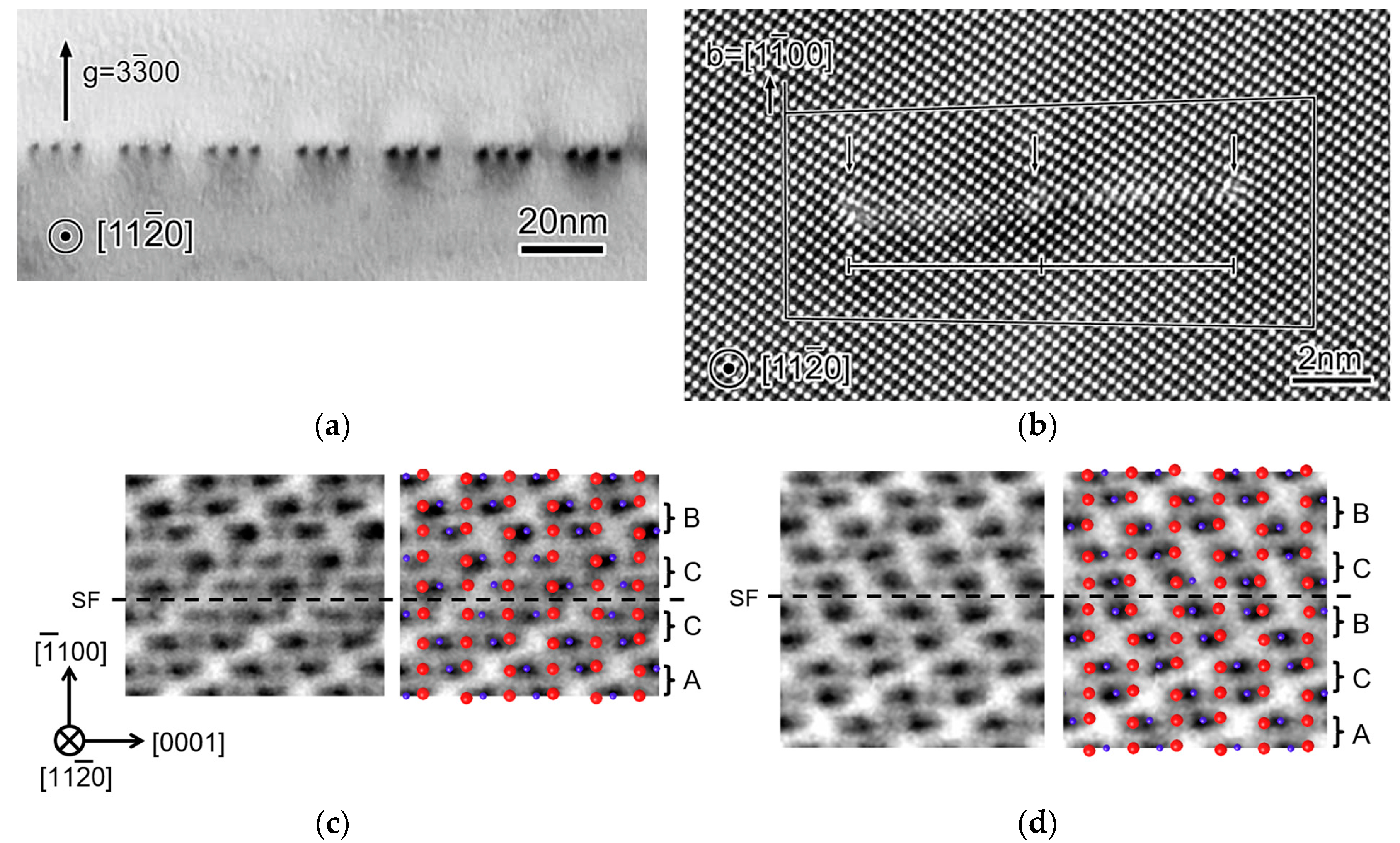
3.2. Low-Angle Tilt Grain Boundary
Figure 3a shows a TEM image of the low-angle 2° tilt grain boundary. It is seen that dislocations are periodically arrayed along the grain boundary. The dislocation structure is divided into two groups, pairs of dislocations and groups of odd-numbered dislocations. Figure 3b shows a dark-field TEM image taken at the same region in Figure 3a using the reflection of g = , where the grain boundary plane is inclined by about 30° from the observation direction. The dislocations are clearly seen as line contrasts. Figure 3c shows an HRTEM image of a dislocation pair. The dislocation is dissociated into two partial dislocations on the plane. The large Burgers circuit shows that the dislocation pair has the Burgers vector of in total. The small Burgers circuits show that each partial dislocation has an edge component of . This component corresponds to the projection of the vectors of and . Therefore, it is considered that the observed structure corresponds to the dissociation of the edge dislocation into the and mixed partial dislocations according to the reaction of Equation (2). The low-angle 10° tilt grain boundary was also investigated and found to consist of the same type of partial-dislocation pairs [25]. The edge dislocation formed in the tilt grain boundary has the dislocation line direction of , and thus this dislocation structure is considered to be equivalent to that of the basal edge dislocation associated with the basal slip [10].
The distances between dislocations d and d1 were measured to be 15 nm and 3.6 nm. Using Equation (3) (where the coefficient attributes ), the formation energy of the stacking fault was estimated to be 0.30 Jm−2 [24]. This value is consistent with that estimated using the low-angle tilt grain boundary, as discussed in Section 3.1.
For the imaging condition of g = in Figure 3b, the partial dislocations with b1 = and with b2 = have strong and weak contrasts, respectively. As seen in Figure 3b, the partial-dislocation pairs (b1–b2 pairs) are imaged as the strong and weak line contrasts. From the contrast features, the configurations of the group of five and thirteen partials are found to be b1b1b2b1b1 and b1b1b2b1b2b1b2b1b2b1b2b1b1. The edge components of the partial dislocations with b1 and b2 are both , whereas their screw components are and , respectively. Therefore, it is found that the 5-partial structure has an edge component of and a screw component of in total, and the 13-partial structure has an edge component of and a screw component of . Note that both of the structures have the same screw component. This suggests that the odd numbered dislocation structures are generated by the twist component of the grain boundary. The averaged interval of the odd-numbered dislocation structures was about 230 nm. Substituting d = 230 nm and |b| = = 0.407 nm into Equation (1), the twist angle is estimated to be 0.10°. This value is possible considering the accuracy of the bicrystal fabrication processes.
The odd-numbered dislocation structures can be written by the general expression as:
where n is an integer. The odd-numbered dislocation structures with the n-value of 0–7 (corresponding to 3 to 17-partial structures) have been found so far [22,26]. The characteristic dislocation configuration in the present grain boundary is explained as follows. An additional twist component to the low-angle tilt grain boundary generates the mixed dislocations into the edge dislocation array. The dislocation dissociates into three partial dislocations with the stacking faults, which are equivalent to that formed between the partial-dislocation pair associated with the dislocation. As a result, the partial dislocations generated from the and dislocations are combined into the odd-numbered partial structures. In addition, there is a variation of the n-values for the odd-numbered partial structures. This would be because the competition between the strain energy and the excess energy of stacking faults. The net screw component of the partial structures with smaller n-values is more localized than that with larger n values, namely that the strain energy decreases with the n-value. In contrast, the area of stacking fault increases with the n-value.
3.3. Low-Angle Tilt Grain Boundary
Figure 4a shows a TEM image of the 2° tilt grain boundary. Dislocation triplets are arrayed along the grain boundary, suggesting that the dislocations dissociated into three partial dislocations with stacking faults. An HRTEM image of a dislocation triplet is shown in Figure 4b. The three partial dislocations connected with the two stacking faults are clearly observed. The Burgers circuit shows that this dislocation triplet has the Burgers vector of in total. Therefore, this dissociation reaction is written as:
This dissociation reaction is known to occur for the slip dislocation associated with the prism-plane slip [5].
The two stacking faults on the plane are formed between three partial dislocations. The stacking sequence of the plane is represented as …ABCABC…. Thus, the stacking faults generated by the fault vector of have structural variations: …ABC/B/ABC…, …ABC/C/ABC…, and …ABC//BCA…, where the position of stacking disorder is indicated by ‘//’. These stacking faults are called interstitial fault type-I (I1), interstitial fault type-II (I2), and vacancy fault (V), respectively [8,27]. Due to the geometric constraint, the combination of the stacking faults formed between the triplet is known to be either of I1-V or I2-V [8,27]. To identify the structure of the stacking faults formed between the partial dislocations, we observed the stacking faults by atomic-resolution STEM.
Figure 4c,d show annular bright-field (ABF) STEM images of the stacking faults, corresponding to the left and the right ones in Figure 4b, respectively. ABF STEM is capable of visualizing atomic columns and even light elements [38,39]. In these images, strong dark contrasts correspond to aluminum columns and weak dark contrasts to oxygen columns, as shown in the atomic structure model in the figure. The stacking sequences of the stacking faults can be directly interpreted as …ABC/C/ABC… (I2) for the left stacking fault and …ABC//BCAB…: (V) for the right stacking fault.
Their stacking fault energies can be estimated by the similar way as discussed in Section 3.1. For the present case, the equations become the following forms:
where α1 is d1/d (d1: the width of staking fault I2) and α2 is d2/d (d2: the width of staking fault V). The experimental distances of d, d1 and d2 were measured to be 22 nm, 4.7–5.1 nm, and 5.5–5.9 nm, respectively. Using these values, the stacking fault energies were estimated to be I2: γ = 0.41–0.46 Jm−2 and V: γ = 0.33–0.37 Jm−2. Theoretical calculations suggested that the stacking fault energies of I1, I2, and V are 0.62–0.63 Jm−2, 0.46 Jm−2, and 0.41 Jm−2, respectively [27,37]. These results agree well with the experimental results.
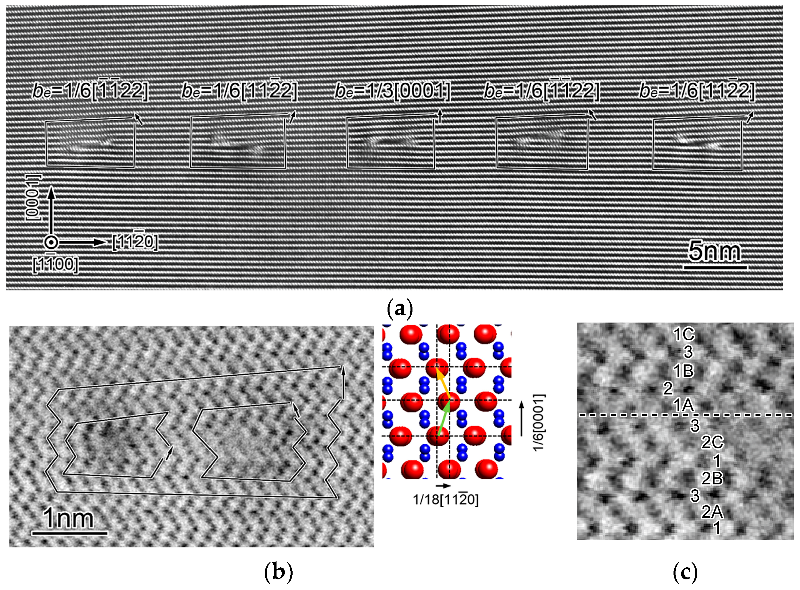
3.4. Low-Angle Tilt Grain Boundary [30]
Figure 5a shows an HRTEM image of the 2° low-angle tilt grain boundary. Five dislocation structures are observed and each dislocation structure appears to consist of two partial dislocations with a stacking fault on the plane. From the Burgers circuits, the edge component of these dislocations is either of , , or . These components do not correspond to a translation vector, and thus these dislocations should be a mixed dislocation with a screw component along the direction. The screw components can be uniquely determined so as to match a possible translation vector as follows:
| (edge) | (screw) | (total) |
The sum of these three vectors is , and their screw components are cancelled out in total. Since the vector is the translation vector perpendicular to the boundary plane, it can be said that the tilt component of the grain boundary is effectively accommodated by groups of these three equivalent dislocations of , , and . This characteristic dislocation configuration is reasonable in terms of dislocation self-energy, which is proportional to the square of Burgers vector. The magnitude of the vector is 1.30 nm and that of vector is 0.513 nm, leading the relationship of |b[0001]|2 > 3 × |b1/3<−1101>|2. Therefore, the triplet of dislocation is considered to be energetically favorable than the single dislocation.
Figure 5b shows an ABF STEM image of the dislocation. The zigzag contrasts along the direction correspond to the configurations of oxygen and aluminum columns as illustrated in the atomic structure at the right. It is clearly seen that the dislocation is dissociated into two partial dislocations with the stacking fault. The Burgers circuits drawn around the partial dislocations indicate that the left and right ones have an edge component of and , respectively. Their screw components, which are necessary to determine the dissociation reaction, are not given by the STEM observations. To identify the Burgers vector of the partial dislocations, instead, we analyzed the fault vector of the stacking fault.
An ABF STEM image of the stacking fault formed between the partial dislocations is shown in Figure 5c. The position of the stacking fault is indicated by the dashed line. As shown in the figure, the stacking sequence along the direction on the projection is …1 2A 3 2B 1 2C 3//1A 2 1B 3 1C…, where the single numbers refer to oxygen layers and the numbers with a letter to aluminum layers. Theoretical calculations revealed that there is the displacement of or across the stacking fault shown in Figure 5c [30], namely that the partial dislocations have a screw component of or . Here, the screw components of the partial dislocations are uniquely determined to be because the partial-dislocation pair has the screw component of in total (see Equation (10)). As a result, the Burgers vectors for the two partial dislocations are identified to be and . Consequently, the dissociation reaction of the mixed dislocations is represented by the following equation:
The dislocation is known to be associated with the pyramidal slip (The and planes are also possible.) [7]. The dissociation reaction of the slip dislocation has not been reported.
The formation energy of the stacking fault can be calculated by a theoretical equation similar to Equation (3). In the present case, however, it should be too complicated to derive such theoretical equations because the grain boundary consists of six kinds of partial dislocations. Instead, the stacking fault energy was numerically calculated using the actual dislocation configurations identified from our experimental observations, and the calculated value was 0.58 Jm−2 [30]. In addition, first-principles calculations suggested the stacking fault energy to be 0.72 Jm−2 [30].
3.5. Low-Angle Tilt Grain Boundary
Figure 6a shows a dark-field TEM image of the low-angle 2° tilt grain boundary taken using g = . The grain boundary appears to be wavy, and relatively broad contrasts and pair contrasts are observed, suggesting that the grain boundary consists of multiple kinds of dislocation structures.
Figure 6b shows an HRTEM image of the grain boundary. A single dislocation and two dislocation pairs are observed, as indicated by the arrows. Figure 6c shows an enlarged image of one of the single dislocations. The single dislocation has an edge component of . Since this component does not correspond to a translation vector, the single dislocation should have a screw component along the direction. The screw component is considered to be (or ), which makes the smallest translation vector of (or ). Therefore, the single dislocation should be the mixed dislocation. An HRTEM image of a dislocation pair dislocation is shown in Figure 6d. This dislocation structure consists of two partial dislocations with a stacking fault on the plane. The Burgers circuits show that the total edge component is , and each partial dislocation has an edge component of . Since vector corresponds to a translation vector, this dislocation structure is considered to be the edge dislocation.
It was found that the low-angle tilt grain boundary consists of not only one kind of dislocation structure. This is because there is no translation vector perpendicular to the grain boundary plane. The vector corresponding to the dislocation pair is at an angle of 84.16° to the grain boundary plane. This vector introduces a component parallel to the grain boundary of = 0.052 nm (along the direction) in addition to the component normal to the grain boundary. This additional component should be cancelled out in total over the grain boundary by another vector. The vector corresponding to the edge component of the dislocation is at an angle of 141.76° to the plane. This vector has a component along the direction of = −0.32 nm, which can compensate the additional components due to the vector. Therefore, it is considered that the dislocation pairs and the dislocations are mixed in the grain boundary so as to cancel out a component along the direction. The ideal ratio of the numers of the dislocation pairs to the dislocations is estimated to be 0.32/0.052 = ~6.2.
Here, we further discuss the structure of the dislocation pair. Theoretical calculations revealed that the stacking fault formed between the partial dislocations has a displacement of and its structure is identical to the stacking fault shown in Figure 5c [32]. The dislocation pair has no screw component in total, and thus the Burgers vectors of the partial dislocations are and . Consequently, it is found that the dissociation reaction of the edge dislocation also corresponds to Equation (11).
3.6. Low-Angle Twist Grain Boundary
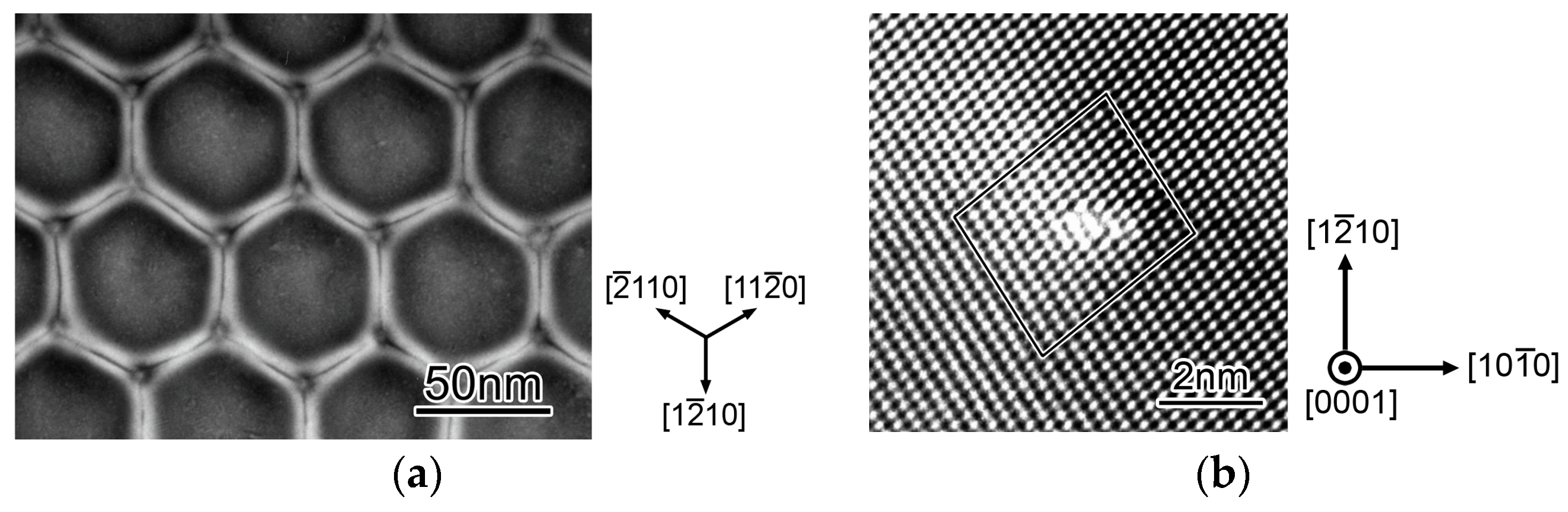
A low-angle twist grain boundary was fabricated by joining two pieces of alumina substrate. The twist angle around the axis was expected to be as much as the cutting accuracy of the substrate sides (<~0.1°). Two TEM samples were prepared: ones for plan-view and for edge-on observations.
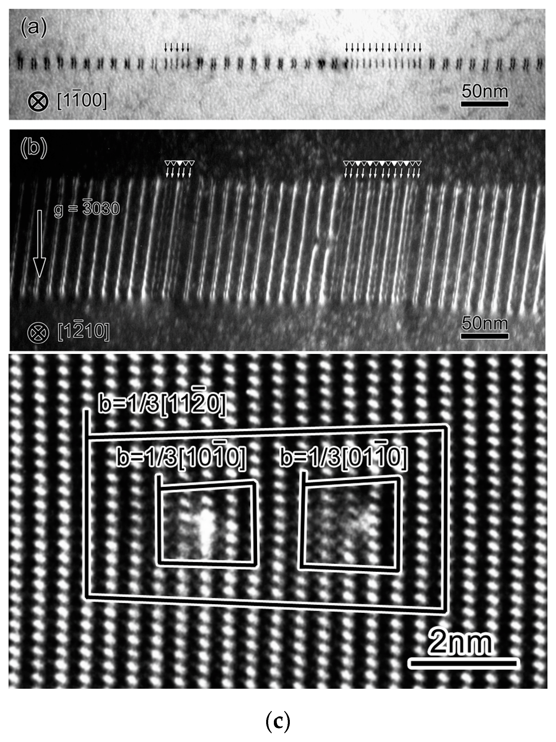
Figure 7a shows a plan-view TEM image of the low-angle twist grain boundary. The observation direction is along the zone axis. A hexagonal dislocation network is formed on the grain boundary. Since these dislocations are parallel to either of the three equivalent directions of , they should correspond to the screw dislocations. The interval of the equivalent dislocations is about 60 nm. Using Equation (1), the twist angle of this grain boundary is estimated to be 0.45°.
An HRTEM image of a screw dislocation in the grain boundary viewed end-on is shown in Figure 7b. The image contrasts are slightly disordered over a few atomic columns, corresponding to the dislocation core region. The circuit drawn around the dislocation core is closed, indicating that this dislocation is a pure screw dislocation. From the image contrasts, the dislocation core is localized within 1 nm or less, and thus the screw dislocation is not dissociated, in contrast to the edge dislocation, as discussed in Section 3.2. The screw dislocation in the present grain boundary corresponds to the basal screw dislocation associated with the basal slip. The basal screw dislocation is likely to have the perfect type core structure, although its core structure has not been reported. If this is the case, it is considered that the basal screw dislocation slips easily in comparison with the basal edge dislocation. This is because the stacking fault generated by the dissociation of the basal edge dislocation is not on the slip plane and does not move without atomic diffusion.
4. Findings and Future Subjects
Our investigations found the dissociation reactions and the core structures of (edge, screw), (edge) and (edge, mixed) dislocations. The partial dislocations generated by the dissociation reactions of Equations (2), (5), and (11) have the Burgers vector of or . The formation of these two partial dislocations can be understood in terms of the stability of stacking faults. The stacking faults on the or planes formed by the partial dislocation are stable (low energy) (formation energy: 0.3–0.5 Jm−2) [11,21,24,27,37], whereas ones on the plane were calculated to be unstable (>1 Jm−2) [36,40]. The stacking fault on the plane formed by the partial dislocation is relatively stable (0.6 Jm−2) [30,32]. The point is that the stability of stacking faults determines the dissociation reaction of dislocations. To examine whether another dissociation reaction is possible, it would be helpful to calculate the relationship between the formation energies of stacking faults and fault vectors for every lattice planes, i.e., generalized stacking fault energies (also known as γ-surfaces) [41].
Screw dislocations except for the dislocation have not been investigated yet. Since the translation vectors of , , , and are on the plane, screw dislocations with either of these vectors are expected to be formed in the low-angle twist grain boundary. Structural analysis of this type of grain boundary will give us further knowledge on screw dislocations in alumina.
5. Conclusions
Alumina bicrystals with a low-angle grain boundary were systematically fabricated and the grain boundaries were observed by TEM. The dislocation structures formed in the low-angle grain boundaries are summarized below:
- (1)
- tilt grain boundary
The perfect edge dislocations dissociate into the and partial dislocations with the stacking fault. The stacking fault energy was estimated to be 0.32 Jm−2.
- (2)
- tilt grain boundary
The perfect edge dislocations dissociate into the and partial dislocations with the stacking fault. The stacking fault energy was estimated to be 0.35 Jm−2. It was also found that an additional screw component in the grain boundary forms the odd-numbered partial dislocation structures represented by .
- (3)
- tilt grain boundary
The perfect edge dislocations dissociate into three partial dislocations with the stacking faults of I2 and V. The stacking fault energies were estimated to be I2: 0.41–0.46 Jm−2 and V: 0.33–0.37 Jm−2.
- (4)
- tilt grain boundary
The misorientation of the grain boundary is accommodated by the groups of the , , and perfect mixed dislocations. Each perfect dislocation dissociates into and partial dislocations with the stacking fault. The stacking fault energy was estimated to be 0.58 Jm−2.
- (5)
- tilt grain boundary
The misorientation of the grain boundary is accommodated by perfect mixed dislocations and perfect edge dislocations. The dislocations are not dissociated, whereas edge dislocations dissociate into and with the stacking fault.
- (6)
- twist grain boundary
The hexagonal network of the prefect screw dislocations is formed. The screw dislocation is not dissociated into partial dislocations.
Acknowledgments
The authors gratefully thank K. Peter D. Lagerlöf, Takahisa Yamamoto, Katsuyuki Matsunaga, Teruyasu Mizoguchi, Matthew F. Chisholm, Hitoshi Nishimura, and Yuki Kezuka for collaborative works on dislocations in alumina. A part of this study was supported by Grant-in-Aid for Specially promoted Research (Grant No. JP17H06094) from the Japan Society for the Promotion of Science (JSPS), the Elements Strategy Initiative for Structural Materials (ESISM) from the Ministry of Education, Culture, Sports, Science, and Technology in Japan (MEXT), Grant-in-Aid for Scientific Research on Innovative Areas “Nano Informatics” (Grant No. JP25106002 and JP25106003) from JSPS, “Nanotechnology Platform” (Project No. 12024046) of MEXT, and JSPS KAKENHI (Grant Nos. JP15H04145 and JP15K20959, and JP17K18983).
Author Contributions
Eita Tochigi drafted the manuscript. All the authors discussed and amended the manuscript.
Conflicts of Interest
The authors declare no conflict of interest.
References
- Sutton, A.P.; Balluffi, R.W. Interfaces in Crystalline Materials; Clarendon Press: Oxford, UK, 1995. [Google Scholar]
- Hirth, J.P.; Lothe, J. Theory of Dislocations, 2nd ed.; Krieger Publishing Company: Malabar, India, 1982. [Google Scholar]
- Snow, J.D.; Heuer, A.H. Slip systems in Al2O3. J. Am. Ceram. Soc. 1973, 56, 153–157. [Google Scholar] [CrossRef]
- Pletka, B.J.; Heuer, A.H.; Mitchell, T.E. Dislocation structures in sapphire deformed basal slip. J. Am. Ceram. Soc. 1974, 56, 136–139. [Google Scholar] [CrossRef]
- Bilde-Sørensen, J.B.; Thölen, A.R.; Gooch, D.J.; Groves, G.W. Structure of dislocation in sapphire. Philos. Mag. 1976, 33, 877–889. [Google Scholar] [CrossRef]
- Mitchell, T.E.; Pletka, B.J.; Phillips, D.S.; Heuer, A.H. Climb dissociation in sapphire (α-Al2O3). Philos. Mag. 1976, 34, 441–451. [Google Scholar] [CrossRef]
- Firestone, R.F.; Heuer, A.H. Creep deformation of 0° sapphire. J. Am. Ceram. Soc. 1976, 59, 13–19. [Google Scholar] [CrossRef]
- Lagerlöf, K.P.D.; Mitchell, T.E.; Heuer, A.H.; Rivière, J.P.; Cadoz, J.; Castaing, J.; Phillips, D.S. Stacking fault energy in sapphire (α-Al2O3). Acta Met. 1984, 32, 97–105. [Google Scholar] [CrossRef]
- Lagerlöf, K.P.D.; Heuer, A.H.; Castaing, J.; Rivière, J.P.; Mitchell, T.E. Slip and twinning in sapphire. J. Am. Ceram. Soc. 1994, 77, 385–397. [Google Scholar]
- Bilde-Sørensen, J.B.; Lawlor, B.F.; Geipel, T.; Pirouz, P.; Heuer, A.H.; Lagerlöf, K.P.D. On basal slip and basal twinning in sapphire (α-Al2O3)—I. Basal slip revisited. Acta Mater. 1996, 44, 2145–2152. [Google Scholar] [CrossRef]
- Nakamura, A.; Yamamoto, T.; Ikuhara, Y. Direct observation of basal dislocation in sapphire by HRTEM. Acta Mater. 2002, 50, 101–108. [Google Scholar] [CrossRef]
- Nakamura, A.; Matsunaga, K.; Tohma, J.; Yamamoto, T.; Ikuhara, Y. Conducting nanowires in insulating ceramics. Nat. Mater. 2003, 2, 453–456. [Google Scholar] [CrossRef] [PubMed]
- Tochigi, E.; Kezuka, Y.; Nakamura, A.; Nakamura, A.; Shibata, N.; Ikuhara, Y. Direct observation of impurity segregation at dislocation cores in an ionic crystal. Nano Lett. 2017, 17, 2908–2912. [Google Scholar] [CrossRef] [PubMed]
- Bouchet, D.; Lartigue-Korinek, S.; Molis, R.; Thibault, J. Yttrium segregation and intergranular defects in alumina. Philos. Mag. 2006, 86, 1401–1413. [Google Scholar] [CrossRef] [Green Version]
- Lartigue-Korinek, S.; Bouchet, D.; Bleloch, A.; Colliex, C. HAADF study of relationship between intergranular defect structure and yttrium segregation in an alumina grain boundary. Acta Mater. 2011, 59, 3519–3527. [Google Scholar] [CrossRef]
- Ikuhara, Y. Nanowire design by dislocation technology. Prog. Mater. Sci. 2009, 54, 770–791. [Google Scholar] [CrossRef]
- Nakamura, A.; Mizoguchi, T.; Matsunaga, K.; Yamamoto, T.; Shibata, N.; Ikuhara, Y. Periodic Nanowire Array at the Crystal Interface. ACS Nano 2013, 7, 6297–6302. [Google Scholar] [CrossRef] [PubMed]
- Matsunaga, K.; Nishimura, H.; Saito, T.; Yamamoto, T.; Ikuhara, Y. High-resolution transmission electron microscopy and computational analyses of atomic structures of symmetric tilt grain boundaries of Al2O3 with equivalent grain-boundary planes. Philos. Mag. 2003, 83, 4071–4082. [Google Scholar] [CrossRef]
- Gemming, T.; Nufer, S.; Kurtz, W.; Rühle, M. Structure and chemistry of symmetrical tilt grain boundaries in α-Al2O3: I, Bicrystals with “clean” interface. J. Am. Ceram. Soc. 2003, 86, 581–589. [Google Scholar] [CrossRef]
- Lartigue-Korinek, S.; Liagege, S.; Kisielowski, C.; Serra, A. Disconnection arrays in a rhombohedral twin in α-alumina. Philos. Mag. 2008, 88, 1569–1579. [Google Scholar] [CrossRef]
- Ikuhara, Y.; Nishimura, H.; Nakamura, A.; Matsunaga, K.; Yamamoto, T. Dislocation structures of low-angle and near-Σ3 grain boundaries in alumina bicrystals. J. Am. Ceram. Soc. 2003, 86, 595–602. [Google Scholar] [CrossRef]
- Nakamura, A.; Matsunaga, K.; Yamamoto, T.; Ikuhara, Y. Multiple dissociation of grain boundary dislocations in alumina ceramic. Philos. Mag. 2006, 86, 4657–4666. [Google Scholar] [CrossRef]
- Shibata, N.; Chisholm, M.F.; Nakamura, A.; Pennycook, S.J.; Yamamoto, T.; Ikuhara, Y. Nonstoichiometric dislocation cores in α-alumina. Science 2007, 316, 82–85. [Google Scholar] [CrossRef] [PubMed]
- Tochigi, E.; Shibata, N.; Nakamura, A.; Yamamoto, T.; Ikuhara, Y. TEM characterization of 2° tilt grain boundary in alumina. Mater. Sci. Forum 2007, 561–565, 2427–2430. [Google Scholar] [CrossRef]
- Tochigi, E.; Shibata, N.; Nakamura, A.; Yamamoto, T.; Lagerlöf, K.P.D.; Ikuhara, Y. Dislocation structure of 10° low-angle tilt grain boundary in α-Al2O3. Mater. Sci. Forum 2007, 558–559, 979–982. [Google Scholar] [CrossRef]
- Tochigi, E.; Shibata, N.; Nakamura, A.; Yamamoto, T.; Ikuhara, Y. Partial dislocation configurations in a low-angle boundary in α-Al2O3. Acta Mater. 2008, 56, 2015–2021. [Google Scholar] [CrossRef]
- Tochigi, E.; Shibata, N.; Nakamura, A.; Mizoguchi, T.; Yamamoto, T.; Ikuhara, Y. Structures of dissociated dislocations and stacking faults of alumina (α-Al2O3). Acta Mater. 2010, 58, 208–215. [Google Scholar] [CrossRef]
- Tochigi, E.; Shibata, N.; Nakamura, A.; Yamamoto, T.; Ikuhara, Y. Dislocation structures in a low-angle tilt grain boundary of alumina (α-Al2O3). J. Mater. Sci. 2011, 46, 4428–4433. [Google Scholar] [CrossRef]
- Tochigi, E.; Kezuka, Y.; Shibata, N.; Nakamura, A.; Ikuhara, Y. Structure of screw dislocations in a low-angle twist grain boundary of alumina (α-Al2O3). Acta Mater. 2012, 60, 1293–1299. [Google Scholar] [CrossRef]
- Tochigi, E.; Nakamura, A.; Mizoguchi, T.; Shibata, N.; Ikuhara, Y. Dissociation of the dislocation and formation of the anion stacking fault on the basal plane in α-Al2O3. Acta Mater. 2015, 91, 152–161. [Google Scholar] [CrossRef]
- Tochigi, E.; Findlay, S.D.; Okunishi, E.; Mizoguchi, T.; Nakamura, A.; Shibata, N.; Ikuhara, Y. Atomic structure characterization of stacking faults on the plane in α-alumina by scanning transmission electron microscopy. AIP Conf. Proc. 2016, 1763, 050003. [Google Scholar]
- Tochigi, E.; Mizoguchi, T.; Okunishi, E.; Nakamura, A.; Shibata, N.; Ikuhara, Y. Dissociation reaction of the edge dislocation in α-Al2O3. J. Mater. Sci. 2018, in press. [Google Scholar] [CrossRef]
- Nakamura, A.; Tochigi, E.; Shibata, N.; Yamamoto, T.; Ikuhara, Y. Structure and configuration of boundary dislocations on low angle tilt grain boundaries in alumina. Mater. Trans. 2009, 50, 1008–1014. [Google Scholar] [CrossRef]
- Chung, D.H.; Simmons, G. Pressure and temperature dependences of isotropic elastic moduli of polycrystalline alumina. J. Appl. Phys. 1968, 39, 5316–5326. [Google Scholar] [CrossRef]
- Gieske, J.H.; Barsch, G.R. Pressure dependence of elastic constants of single crystalline aluminum oxide. Phys. Stat. Sol. 1968, 29, 121–131. [Google Scholar] [CrossRef]
- Kenway, P.R. Calculated stacking-fault energies in α-Al2O3. Philos. Mag. B 1993, 68, 171–183. [Google Scholar] [CrossRef]
- Jhon, M.H.; Glaeser, A.M.; Chrzan, D.C. Computational study of stacking faults in sapphire using total energy methods. Phys. Rev. B 2005, 71, 214101. [Google Scholar] [CrossRef]
- Okunishi, E.; Ishikawa, I.; Sawada, H.; Hosokawa, F.; Hori, M.; Kondo, Y. Visualization of light elements at ultrahigh resolution by STEM annular bright field microscopy. Microsc. Microanal. 2009, 15, 164–165. [Google Scholar] [CrossRef]
- Findlay, S.D.; Shibata, N.; Sawada, H.; Okunishi, E.; Kondo, Y.; Yamamoto, T.; Ikuhara, Y. Robust atomic resolution imaging of light elements using scanning transmission electron microscopy. Appl. Phys. Lett. 2009, 95, 191913. [Google Scholar] [CrossRef]
- Marinopoulos, A.G.; Elsässer, C. Density-functional and shell-model calculations of the energies of basal-plane stacking faults in sapphire. Philos. Mag. Lett. 2001, 81, 329–338. [Google Scholar] [CrossRef]
- Duesberya, M.S.; Vitek, V. Plastic anisotropy in b.c.c. transition metals. Acta Mater. 1998, 46, 1481–1492. [Google Scholar] [CrossRef]
Figure 1.
Schematic illustrations of low-angle grain boundaries: (a) tilt boundary; (b) twist boundary. Typical dislocation structures in (c) tilt boundary; (d) twist boundary.
Figure 1.
Schematic illustrations of low-angle grain boundaries: (a) tilt boundary; (b) twist boundary. Typical dislocation structures in (c) tilt boundary; (d) twist boundary.
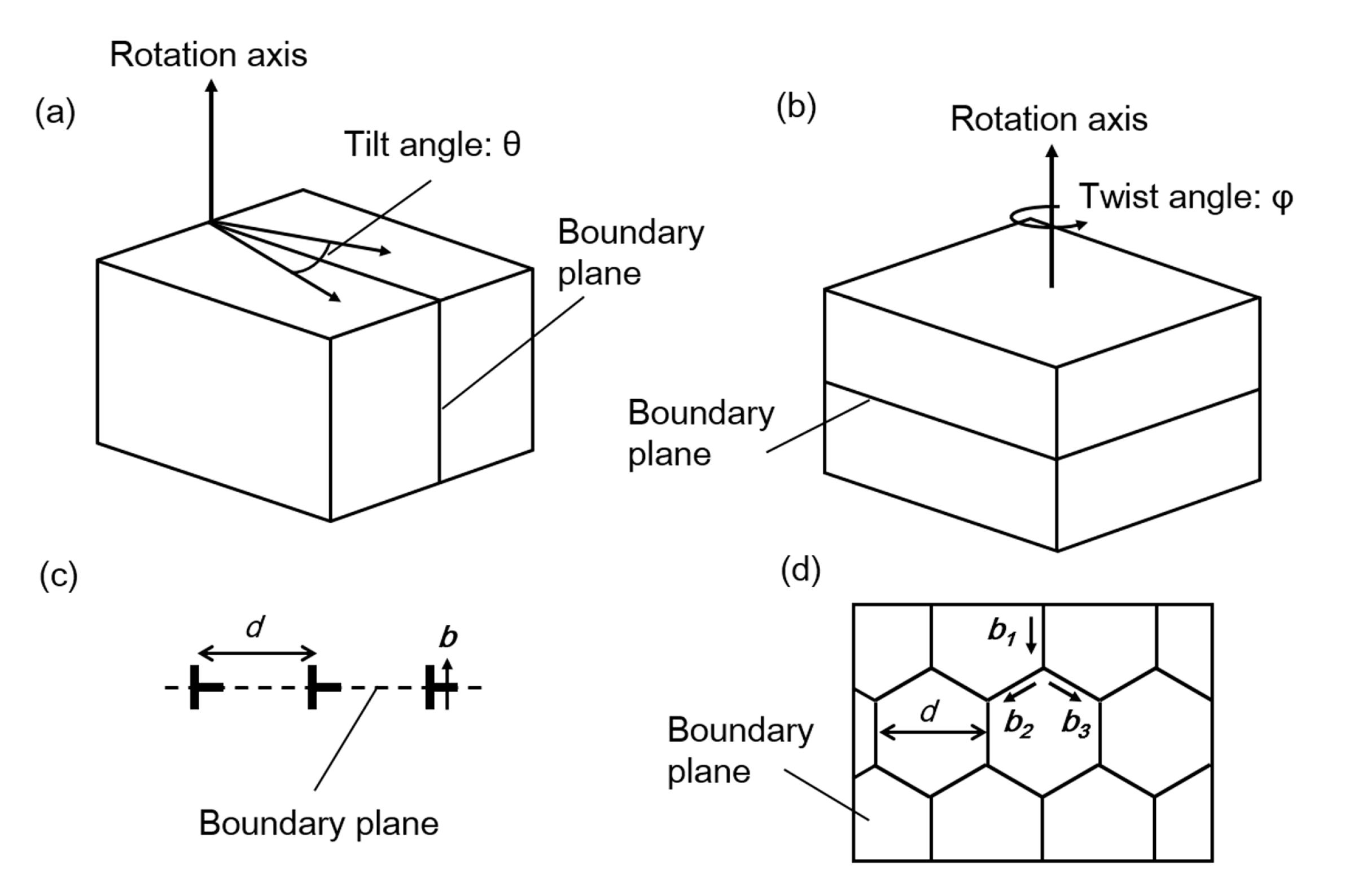
Figure 2.
(a) TEM image of the 2° low-angle tilt grain boundary. Partial-dislocation pairs are formed along the grain boundary. (b) HRTEM image of a partial dislocation pair. The grain boundary is parallel to the vertical direction. The large Burgers circuit shows edge component of , and the small circuits show edge components of and . The images shown are adapted from [21] and reprinted with the permission of the American Ceramics Society.
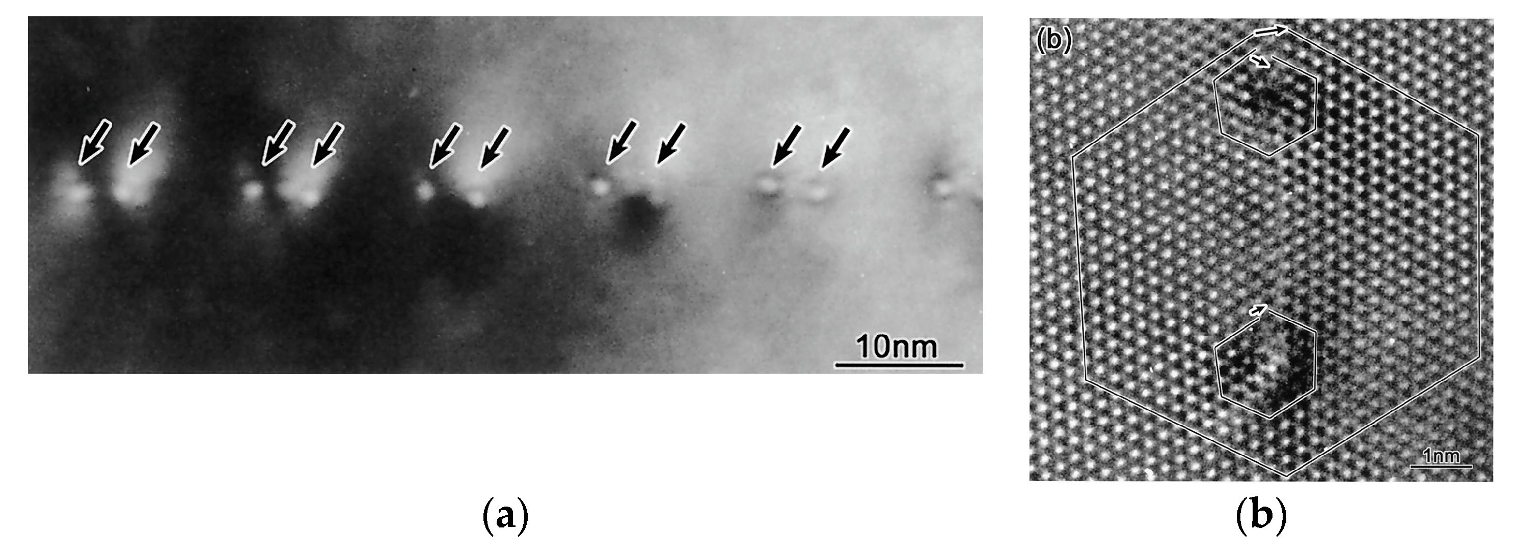
Figure 3.
(a) TEM image of the 2° low-angle tilt grain boundary. The grain boundary consists of partial-dislocation pairs and groups of 5 and 13 partial dislocations. (b) dark-field TEM image taken at the same region in (a) using g = , where the grain boundary plane is inclined by about 30°. Open and filled triangles indicate and partial dislocations, respectively. (c) HRTEM image of a partial-dislocation pair viewed along the zone axis. From the Burgers circuits, it is found that the dislocation pair has the Burgers vector of and the partial dislocations have and . The images (a) and (b) are adapted from [26] and reprinted with the permission of Elsevier B.V. (Amsterdam, Netherlands).

Figure 4.
(a) TEM image of the 2° low-angle tilt grain boundary. The grain boundary consists of dislocation triplets. (b) HRTEM image showing one of the dislocation triplets. The Burgers circuit indicates the Burgers vector of , suggesting that the dislocation is dissociated into partial dislocations with two stacking faults in between. (c) ABF STEM image of the left stacking fault in (b). The atomic structure model overlapped with the image is shown at the right panel. The stacking sequence is …ABC/C/AB…: I2. (d) The right stacking fault in (b). The stacking sequence is …ABC//BCAB…: V. The images (a,b) are adapted from [27] and reprinted with the permission of Elsevier B.V. The images (c,d) are adapted from [31], a proceedings paper published by AIP Publishing LLC (Melville, New York, NY, US).

Figure 5.
(a) HRTEM image of the 2° low-angle tilt grain boundary. The grain boundary consists of dislocations having an edge component of , , or . Each dislocation is dissociated into two partial dislocations with a stacking fault on the plane; (b) ABF STEM image of the dislocation having an edge component of . The Burgers circuits drawn around the partial dislocations indicate edge components of and , as seen in the atomic structure on the right-hand side. (c) enlarged image of the stacking fault formed between the partial dislocations. The stacking sequence is represented as …1 2A 3 2B 1 2C 3//1A 2 1B 3 1C… in the projection. The images (a,b) are adapted from [30] and reprinted with the permission of Elsevier B.V.

Figure 6.
(a) dark-field TEM image of the low-angle 2° tilt grain boundary taken using g = . In the grain boundary, relatively broad contrasts and pair contrasts are seen. (b) HRTEM image of the grain boundary. A single dislocation and two dislocation pairs are observed. The arrows indicate the dislocation core positions. (c) enlarged image of the single dislocation. This dislocation has an edge component of . (d) enlarged image of the dislocation pair. Dislocation is dissociated into partial dislocations with a stacking fault on the plane. The partial dislocations have an edge component of . The images shown are adapted from [28] and reprinted with the permission of Springer Nature (Berlin, Germany).
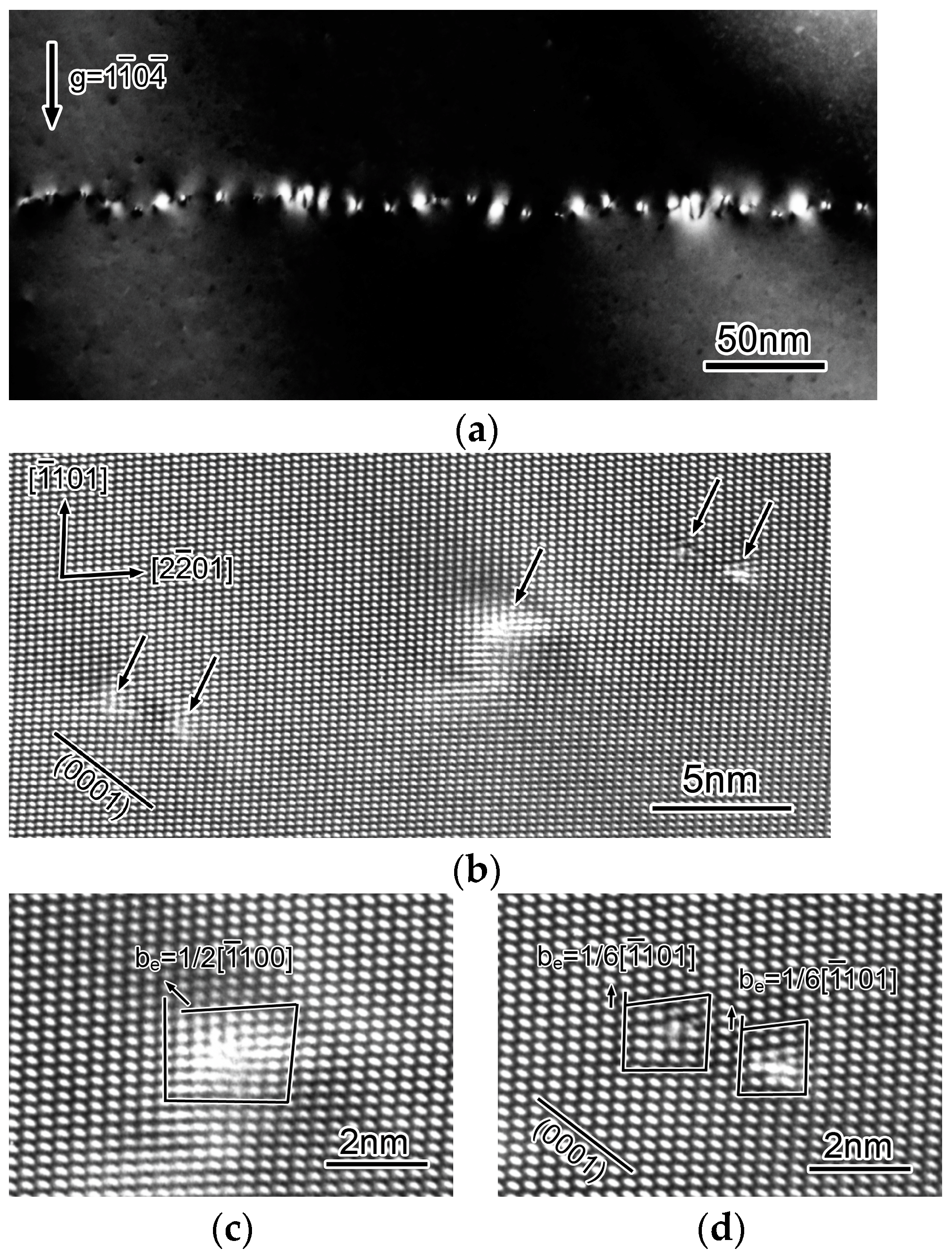
Figure 7.
(a) plan-view TEM image of the low-angle twist grain boundary. A hexagonal dislocation network is clearly seen. The dislocation lines are parallel to either of , , and directions, indicating that they are screw dislocations. (b) HRTEM image showing the end-on view of the screw dislocation. The screw dislocation is not dissociated. The images shown are adapted from [29] and reprinted with the permission of Elsevier B.V.


Table 1.
The low-angle grain boundaries investigated in this study.
| Notation | Type | Misorientation Angle | Burgers Vector Expected |
|---|---|---|---|
| tilt | 2°, 6°, 8° | ||
| tilt | 2°, 10° | ||
| tilt | 2° | ||
| tilt | 2° | ||
| tilt | 2° | ||
| twist | ~0° |
© 2018 by the authors. Licensee MDPI, Basel, Switzerland. This article is an open access article distributed under the terms and conditions of the Creative Commons Attribution (CC BY) license (http://creativecommons.org/licenses/by/4.0/).
Share and Cite
MDPI and ACS Style
Tochigi, E.; Nakamura, A.; Shibata, N.; Ikuhara, Y. Dislocation Structures in Low-Angle Grain Boundaries of α-Al2O3. Crystals 2018, 8, 133. https://doi.org/10.3390/cryst8030133
AMA Style
Tochigi E, Nakamura A, Shibata N, Ikuhara Y. Dislocation Structures in Low-Angle Grain Boundaries of α-Al2O3. Crystals. 2018; 8(3):133. https://doi.org/10.3390/cryst8030133
Chicago/Turabian StyleTochigi, Eita, Atsutomo Nakamura, Naoya Shibata, and Yuichi Ikuhara. 2018. "Dislocation Structures in Low-Angle Grain Boundaries of α-Al2O3" Crystals 8, no. 3: 133. https://doi.org/10.3390/cryst8030133
Note that from the first issue of 2016, this journal uses article numbers instead of page numbers. See further details here.