An Improved Organic Solar Cell Lumped-Parameter Equivalent Circuit Model


College of Information Science and Engineering, Huaqiao University, Xiamen 361021, China
*
Author to whom correspondence should be addressed.
†
These two authors contributed equally to this work.
Crystals 2018, 8(7), 277; https://doi.org/10.3390/cryst8070277
Submission received: 26 May 2018
/
Revised: 24 June 2018
/
Accepted: 27 June 2018
/
Published: 30 June 2018
(This article belongs to the Special Issue Selected Papers from Taiwan Association for Academic Innovation, TAAI 2018)
Abstract
:An improved lumped-parameter equivalent circuit model is proposed to describe S-shaped I–V characteristics of organic solar cells (OSCs). This model originates but differs from Mazhari’s model. As a minor but important modification, a shunt resistance is added to Mazhari’s model to increase the accuracy of simulating the S-shaped kink in the third quadrant. Subsequently, we present a terminal current-voltage equation set and derive an analytical solution to the improved model. Furthermore, we verify the analytical solution to our model by using the least square method and validate our model by using the experimental I–V curves examined from OSCs. Compared with Mazhari’s model, our model has greater accuracy in interpreting the S-shaped kink with linear-like rise in the third quadrant. As a result, our improved model is suitable to explain the S-shaped I–V characteristics of organic solar cells in the whole operational region, especially for the S-shaped kink in the third quadrant.
1. Introduction
Over the last two decades, organic photovoltaic devices [1] have attracted much attention and undergone intensive research due to their many potential advantages over conventional silicon-based solar cells, such as low-cost printing [2] and fabrication on flexible substrate [3]. However, the power conversion efficiency (PCE) of organic solar cells (OSCs) still cannot approach that of conventional silicon-based solar cells because the S-shaped kinks that are tested according to the I–V characteristics of polymer OSCs [4,5] can damage the PCE. Recently, the bilayer cell structure based on heterojunction [6,7] has been reported to give a crucial improvement in PCE, but the efficiency so far is not high enough. It is noted that a lumped-parameter equivalent circuit model of OSCs is useful to explain three factors [8] impacting PCE—short-circuit current, open-circuit voltage, and fill factor—and to optimize the design of photovoltaic devices by providing a quantitative analysis for I–V characteristics.
The conventional equivalent circuit models [9,10] of Si-based solar cells obviously cannot reasonably interpret the S-shaped kink observed in OSCs, because the constant photo-generated current source, in parallel with a single diode, only represents the J-shaped I–V curves. Among the multiple-diode equivalent circuit models [11,12,13,14,15,16,17], Mazhari’s model [11] is regarded as the simplest model including seven parameters used in simulations, while the other models [12,13,14,15,16,17] contain at least eight fitting parameters. Mazhari’s model is able to provide an electrical explanation [18] of the OSC S-shaped kink with exponential-like rise in the first quadrant, but it fails to demonstrate the linear-like rise of the S-shaped kink of OSCs in the third quadrant [19].
In this paper, we propose an improved lumped-parameter equivalent circuit model by modifying Mazhari’s model, in order to give accurate predictions on I–V characteristics of OSCs, especially for the linear-like upturn in the S-shaped kink in the third quadrant. The rest of the paper is organized as follows. In Section 2, the set of I–V equations in the improved model is shown and the analytical solution is derived. In Section 3, we verify the solution by using the least square method results. In Section 4, we compare our model and Mazhari’s model with experimental data [20], and discuss why our model is more accurate. Finally, the conclusions are summarized in Section 5.
2. Improved Model and Its Analytical Solution
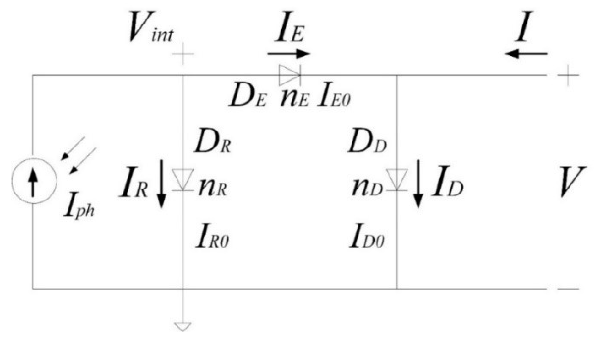
As shown in Figure 1, Mazhari’s model consists of three diodes (i.e., DD, DR, and DE) and a photo-generated current source Iph without any series or shunt resistances. In the above-mentioned diodes, DD simulates the dark current, DR models the recombination current, and DE describes the extraction current. The absence of series or shunt resistances leads to the introduction of major errors in the process of simulating the S-shaped kink in the third quadrant.
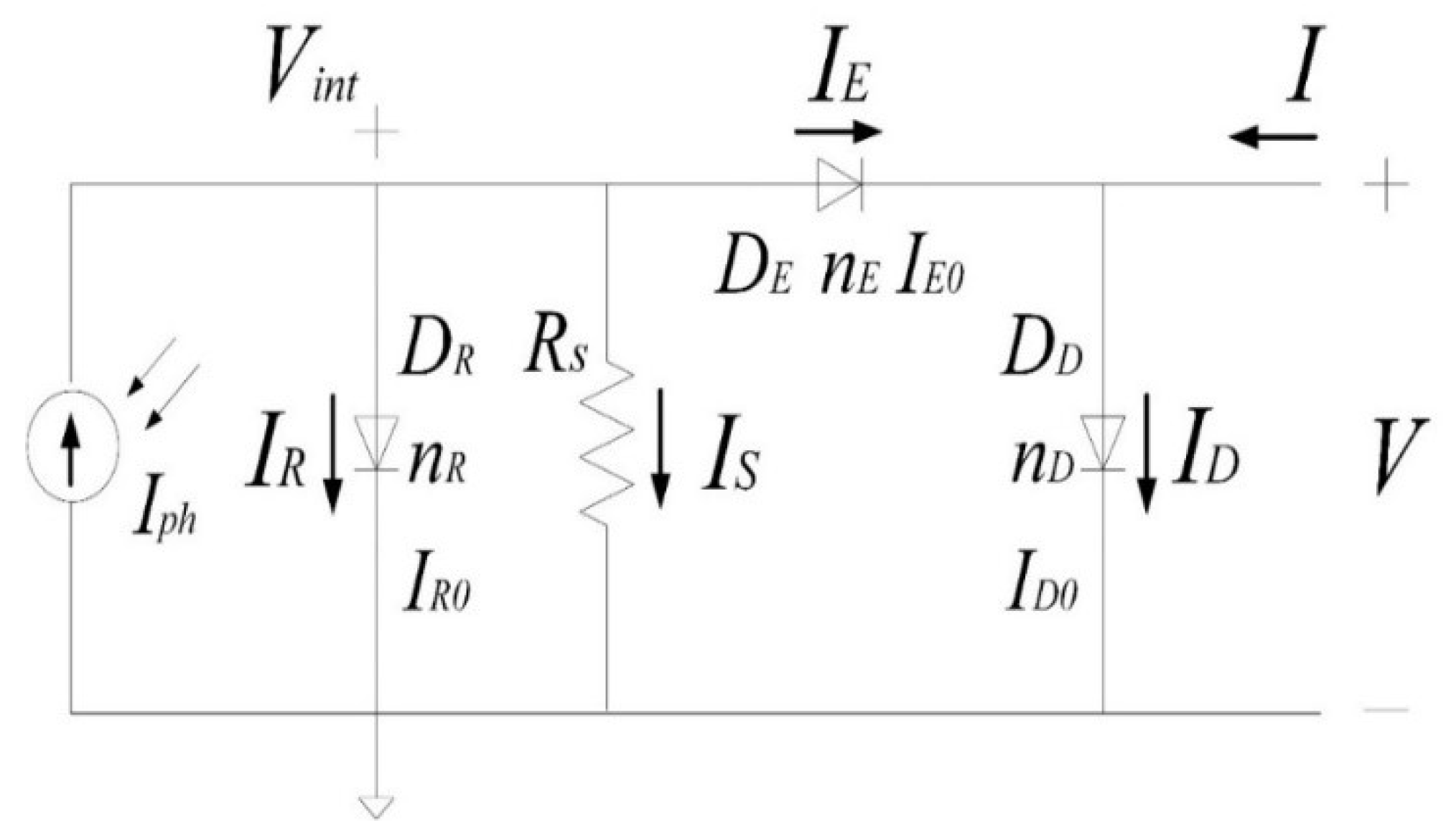
Based on Mazhari’s model, we propose an improved model as shown in Figure 2. We add a shunt resistance with the diode DR to supply a linear item in the relationship between terminal current I and voltage V in Figure 2, which is beneficial for illustrating the S-shaped kink with linear-like rise in the third quadrant, as shown in Section 4. In addition, there are two things deserving of our attention. From the aspect of the circuit’s topological structure, adding the shunt resistance Rs with the diode DR in Figure 2 is equivalent to placing the resistance directly in series or in parallel with the photocurrent, according to the law of external equivalence. From the physical significance aspect, the shunt resistance Rs with DR in Figure 2 represents the power conversion efficiency (PCE) loss resulting from the contact resistances between electrode and acceptor, between acceptor and donor, and between donor and electrode.
In Figure 2, at two earth-free nodes, we use Kirchhoff’s current law and Shockley’s well-known ideal diode current equation [21] to obtain two node current equations as
It is worth noting that Equation (2) can be directly applied to Figure 1, but the linear item introduced by the shunt resistance that RS is added into Equation (1) is different from that in Figure 1. Here, Vint is the voltage drop across the recombination diode DR. nD, nR, and nE are the ideality factors of three diodes representing the divergence from the ideal diode. ID0, IR0, and IE0 are the reverse saturation currents of three diodes. Vt is the thermal voltage symbolized by kT/q, where k is the Boltzmann constant, T is the absolute temperature, and q is the electron charge.
Aiming at roundly demonstrating the S-shaped I–V characteristics of OSCs, implementing our improved model into OSCs’ I–V characteristic simulations in compact format, and facilitating the computer-aided-design, we should derive the accurate and efficient solution of the equation set of Equations (1) and (2) to demonstrate the terminal current I as a function of the terminal voltage V in the improved model, i.e., I–V characteristics of OSCs. Unfortunately, the above equation set cannot be solved directly because Equations (1) and (2) are transcendental equations including at least two exponents. Although we can use the least square method to find the accurate solution of the equation set, this method actually consumes much more computation time, leading to reduced simulation efficiency.
In this paper, we pay more attention to Equation (1) rather than substituting Equation (1) into Equation (2) and eliminating Vint to directly solve the implicit I–V equation. We use the Newton–Raphson root-finding scheme [19], as a trade-off method between accuracy and efficiency, to derive an analytical solution of Equation (1) obtaining the computation results of Vint as a function of V. Subsequently, we substitute Vint into Equation (2) to get the results of the I–V equation in Figure 2. It is noted that the Newton–Raphson root-finding scheme adopted in solving Equation (1) processes the fast convergence and enough computation accuracy.
3. Numerical Verification and Discussion
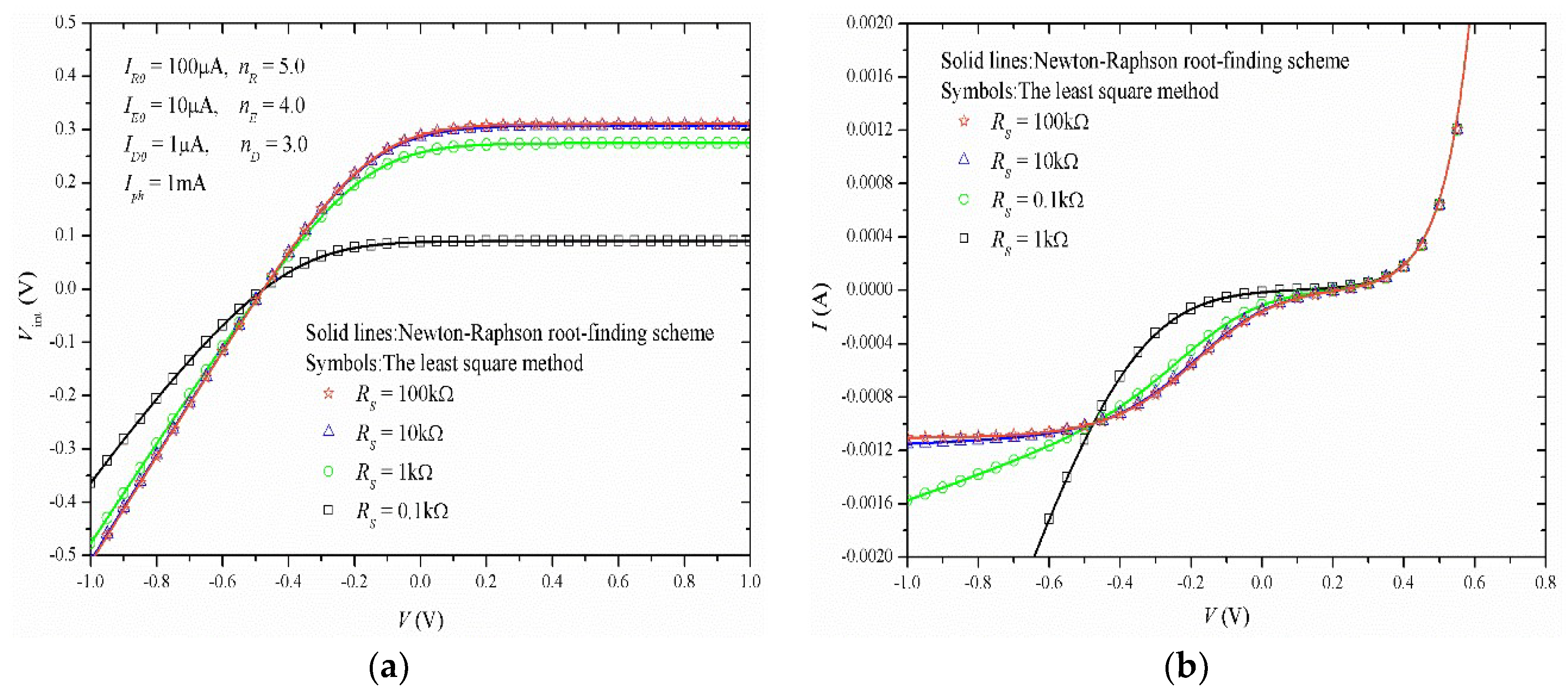
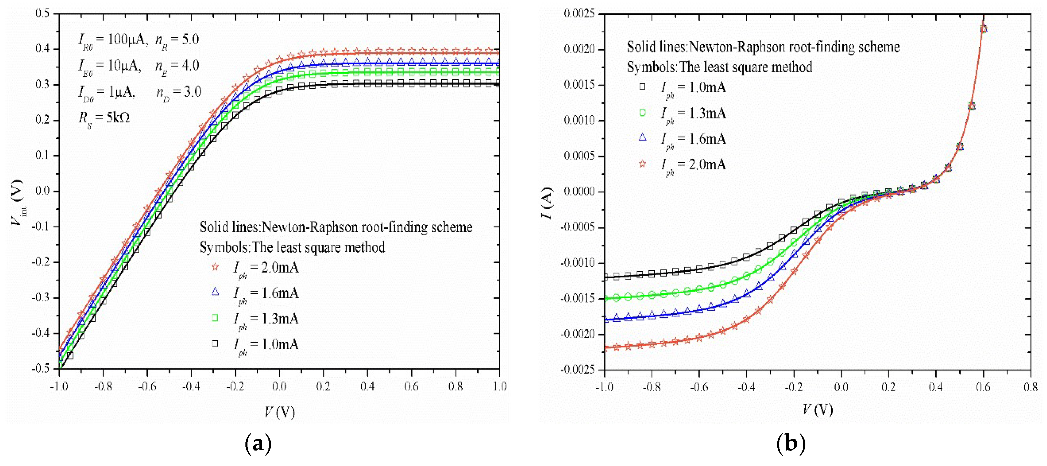
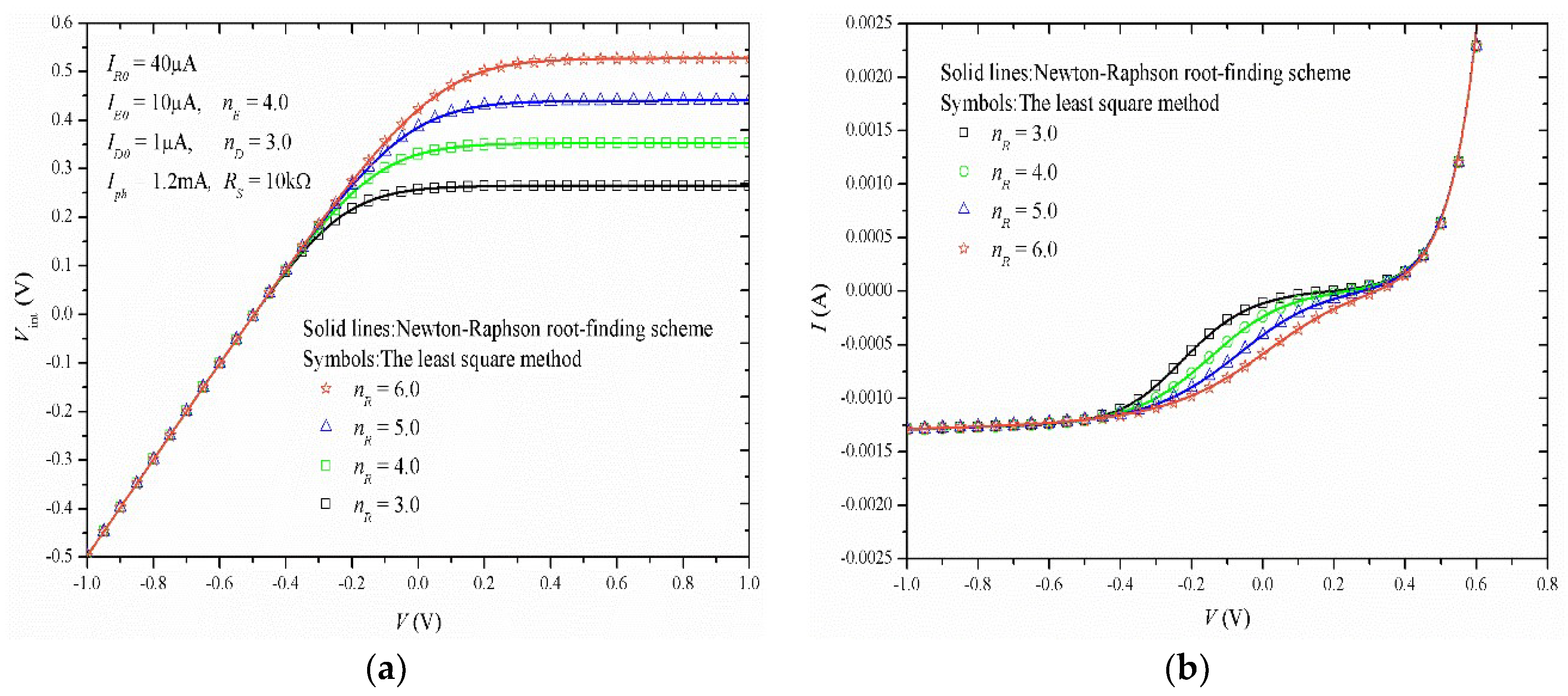
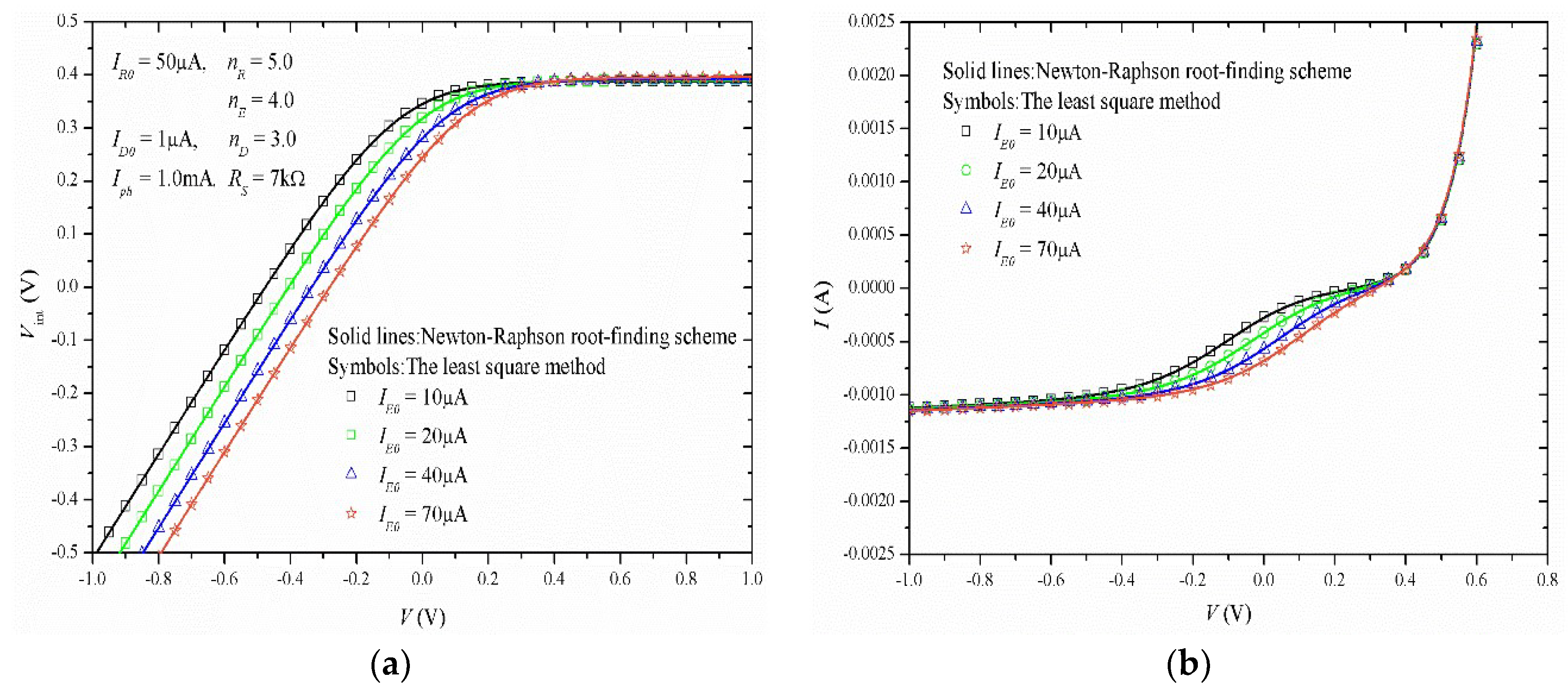
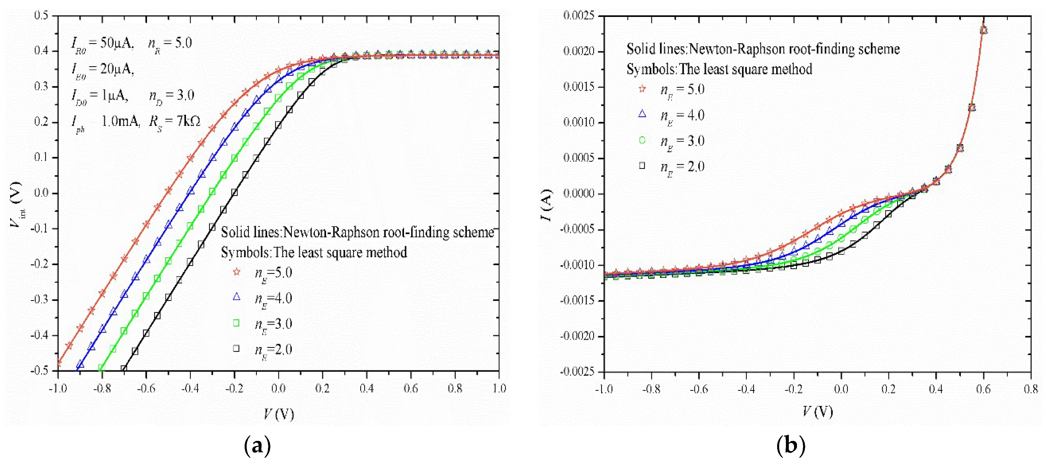
In this section, we use the least square method to verify the solution derived by the Newton-Raphson root-finding scheme of our improved model. In Figure 3, Figure 4, Figure 5, Figure 6, Figure 7 and Figure 8, the verifications show that good agreements between our solutions and the least square method results can be obtained and our improved model can describe the S-shaped I–V characteristics of OSCs. Here, we can requisite the fitting parameters used in simulations by using the systematic parameter extraction procedure presented in Reference [11] or Reference [18].
Furthermore, we will now discuss the influences of the different fitting parameters on Vint and I. Firstly, Figure 3 shows that RS has an effect on both Vint and I. RS determines the slopes of Vint (shown in Figure 3a) and I (shown in Figure 3b) as a function of V in the third quadrant, respectively. It is noted that RS has little effect on Vint and I while RS is larger than 1 kΩ. In fact, this is in consistent with the circuit structure in Figure 1. If RS comes into infinity, our improved model in Figure 2 would degrade into Mazhari’s model in Figure 1. Secondly, Figure 4 shows that Iph can affect the quantities of Vint in the whole operational region and I in the third quadrant, but not the slopes of Vint and I. Thirdly, Figure 5 and Figure 6 show that the recombination diode DR has an important influence on the characteristics of OSCs. On the one side, in Figure 5a, we can observe that IR0 only affects the results of Vint in the first quadrant. In Figure 5b, IR0 affects the results of I only in the third quadrant. On the other side, in Figure 6a,b, the role played by nE is analogous to that of IR0. On the contrary, IE0 and nE of the extraction diode DE can only influence the results of Vint in the first quadrant, but not in the third quadrant, as shown in Figure 7a and Figure 8a. At the same time, both IE0 and nE can only affect the results of I in the third quadrant, as shown in Figure 7b and Figure 8b.
4. Experimental Verification and Comparison with Mazhari’s Model
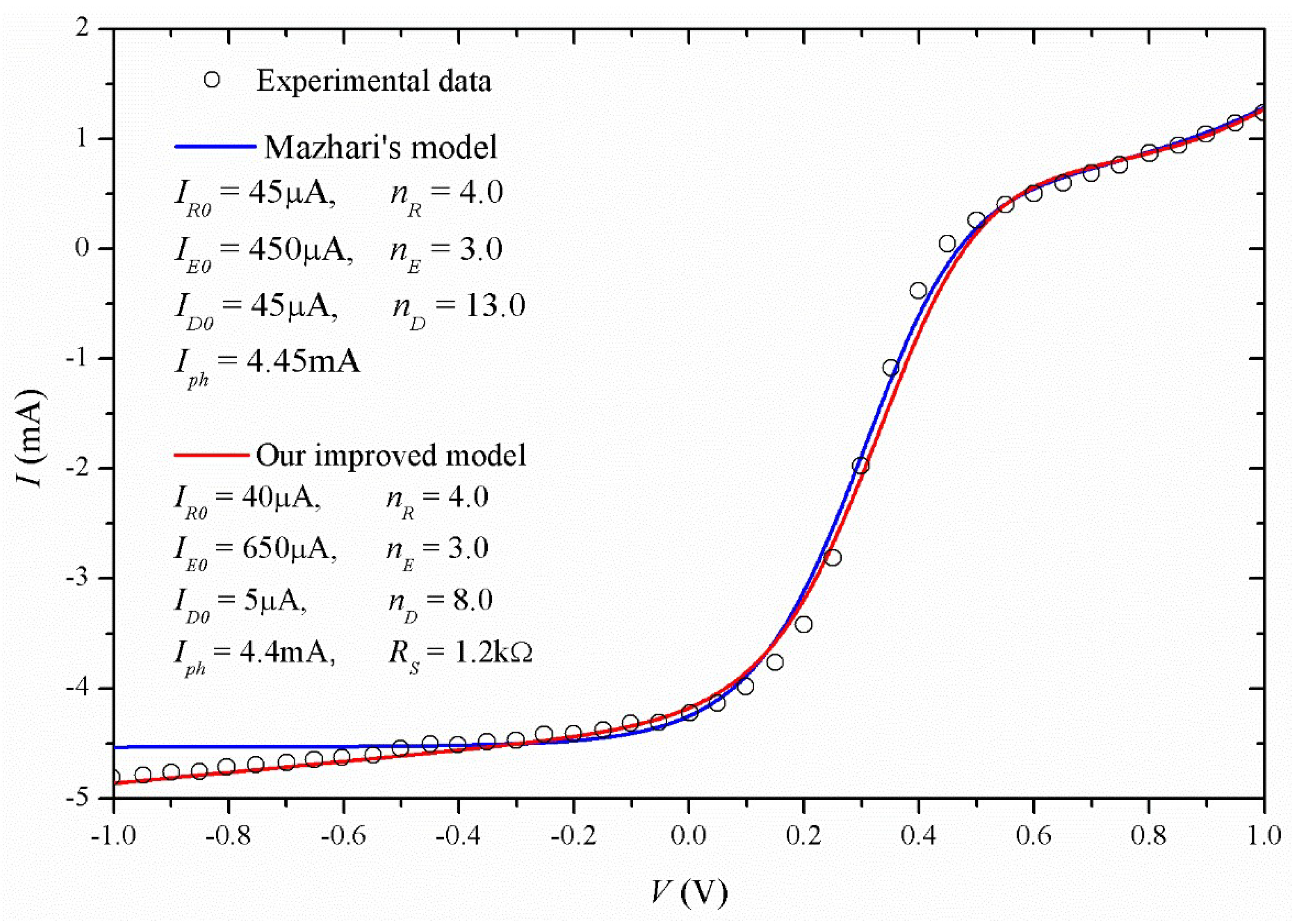
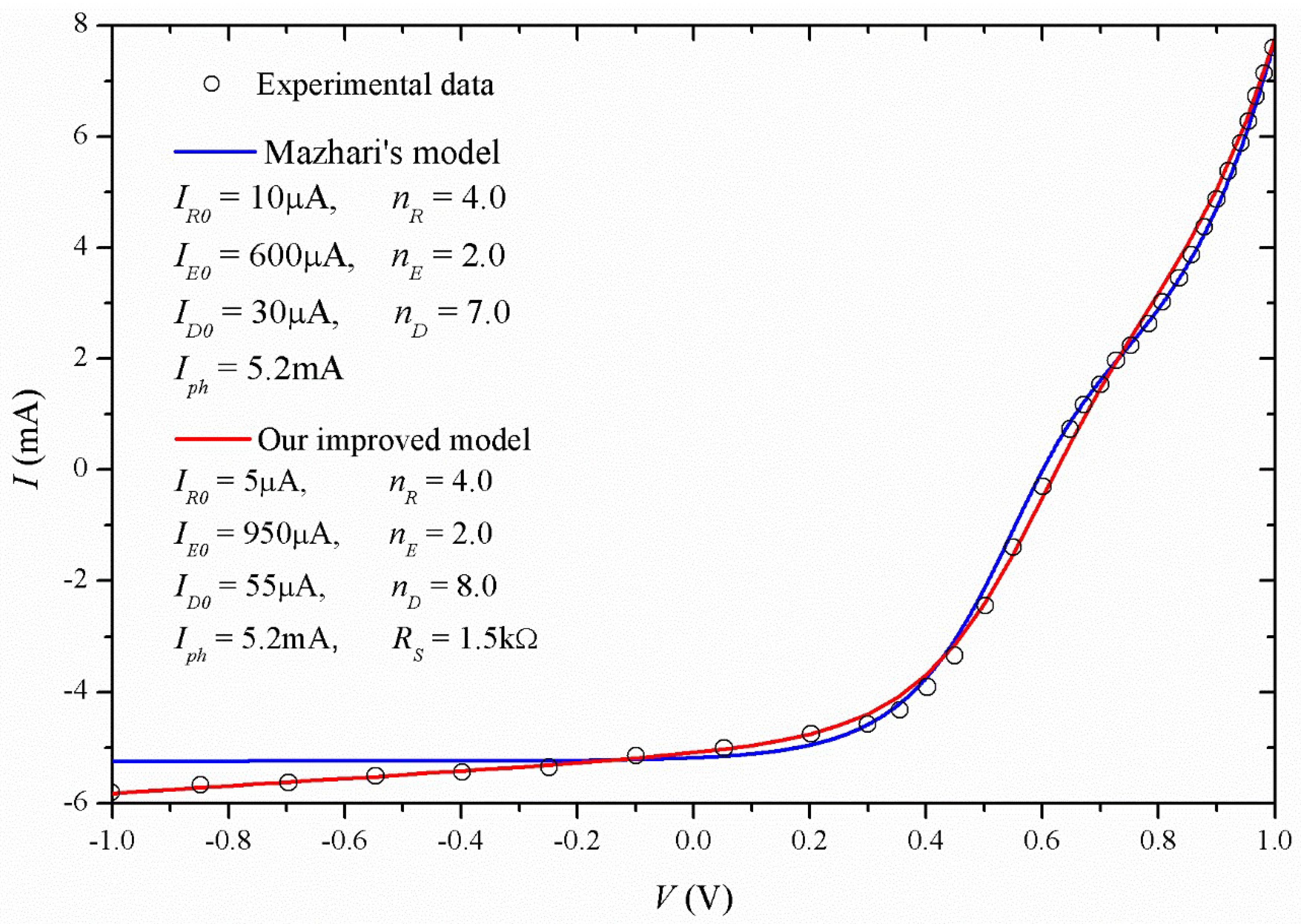
In Figure 9, Figure 10, Figure 11, Figure 12 and Figure 13, we compare the solutions of our improved model with experimental data [19] to verify our model in practice. Simultaneously, the results simulated by Mazhari’s model are shown in Figure 9, Figure 10, Figure 11, Figure 12 and Figure 13, which may be compared with our improved model.
For the solar cells in Reference [19], the enhanced electron acceptor (fullerene C60) and donor (purified Poly[2-methoxy-5-(2-ethylhexyloxy)-1,4-phenylene-vinylene]) bilayer films were prepared on clean ITO glass coated with 50 nm of PEDOT:PSS and 50 nm of Al cathode, with the aim of increasing the power conversion efficiency (PCE). In the N2 atmosphere, the solar cells in [19] were exposed to 1000 W/m2 simulated AM1.5G sunlight, and the I–V characteristics were measured and shown as symbols in Figure 9, Figure 10, Figure 11, Figure 12 and Figure 13.
According to Figure 9, Figure 10, Figure 11, Figure 12 and Figure 13, and combining the equation set of (1) and (2), we can observe that our improved model can simulate the S-shaped kink with both the exponent-like rise in the first quadrant and the linear-like rise in the third quadrant. From the view of physical significance, the shunt resistance should be added to the loss of the current. From the view of circuit structure, our improved model can degrade into Mazhari’s model under the condition that RS goes into infinity. From the view of simulation results, we can observe that our improved model can give more accurate predictions on the linear-like rise of the S-shaped kink in the third quadrant, compared with Mazhari’s model. This is the reason why the shunt resistance RS must be introduced in our improved model. It is interesting that the slope of the S-shaped kink in the third quadrant decreases, but the shunt resistance RS increases as the annealing temperature increases. The probable reason is that the increase of annealing temperature results in the increase of contact resistance Rs. In addition, the higher annealing temperature leads to the I–V curves of OSCs changing from S-shape into J-shape. This may result from the mixture of donor and acceptor.
5. Conclusions
In this paper, we proposed an improved model based on Mazhari’s model and derived the analytical solution of our improved model by using the Newton-Raphson root-finding scheme. High accuracy and efficiency of solutions show that our improved model, as a lumped-parameter equivalent circuit model, can be used to simulate the S-shaped I–V characteristics of organic solar cells (OSCs). Compared with Mazhari’s model, the simulation results of our improved model for S-shaped kink are more accurate in the third quadrant. Finally, we used the least square method and experimental data to verify our solutions of the improved model. As a result, such an improved model can be adopted to substitute for Mazhari’s model to give more accurate predictions on the S-shaped I–V characteristics of OSCs, especially for the S-shaped kink in the third quadrant.
Author Contributions
C.X. and F.Y. conceived and wrote the paper and designed and performed the simulations; G.H. and W.L. finally analyzed the data; C.X. contributed to analysis tools.
Funding
This work was funded partially by the Scientific Research Funds of Huaqiao University under grant 16BS706 and partially by the Scientific Research Funds for the Young Teachers of Fujian Province under grant JAT170034.
Conflicts of Interest
The authors declare no conflicts of interest.
References
- Wagenpfahl, A.; Rauh, D.; Binder, M.; Deibel, C.; Dyakonov, V. S-shaped current-voltage characteristics of organic solar devices. Phys. Rev. B 2010, 82, 115306. [Google Scholar] [CrossRef] [Green Version]
- Tran, V.H.; Ambade, R.B.; Ambade, S.B.; Lee, S.H.; Lee, I.H. Low-temperature solution-processed SnO2 nanoparticles as cathode buffer layer for inverted organic solar cells. ACS Appl. Mater. Interfaces 2017, 9, 1645–1653. [Google Scholar] [CrossRef] [PubMed]
- Kim, T.; Kim, J.-H.; Kang, T.E.; Lee, C.; Shin, M.; Wang, C.; Ma, B.; Jeong, U.; Kim, T.-S.; Kim, B. Flexible, highly efficient all-polymer solar cells. Nat. Commun. 2015, 6, 8547. [Google Scholar] [CrossRef] [PubMed] [Green Version]
- He, Z.; Zhong, C.; Su, S.; Xu, M.; Wu, H.; Cao, Y. Enhanced power-conversion efficiency in polymer solar cells using an inverted device structure. Nat. Photonics 2012, 6, 591–595. [Google Scholar] [CrossRef]
- Liu, Y.; Zhao, J.; Li, Z.; Mu, C.; Ma, W.; Hu, H.; Jiang, K.; Lin, H.; Ade, H.; Yan, H. Aggregation and morphology control enables multiple cases of high-efficiency polymer solar cells. Nat. Commun. 2014, 5, 5293. [Google Scholar] [CrossRef] [PubMed] [Green Version]
- Chavali, R.V.K.; Li, J.V.; Battaglia, C.; Wolf, S.; Gray, J.L.; Alam, M.A. A generalized theory explains the anomalous Suns–Voc response of Si heterojunction solar cells. IEEE J. Photovolt. 2017, 7, 169–176. [Google Scholar] [CrossRef]
- Yoshikawa, K.; Kawasaki, H.; Yoshida, W.; Irie, T.; Konishi, K.; Nakano, K.; Uto, T.; Adachi, D.; Kanematsu, M.; Uzu, H. Silicon heterojunction solar cell with interdigitated back contacts for a photo conversion efficiency over 26%. Nat. Energy 2017, 2, 17032. [Google Scholar] [CrossRef]
- Castro, F.A.; Heier, J.; Nuesch, F.; Hany, R. Origin of the kink in current-density versus voltage curves and efficiency enhancement of polymer-C60 heterojunction solar cells. IEEE J. Sel. Top. Quantum Electron. 2010, 16, 1690–1699. [Google Scholar] [CrossRef]
- Jain, A.; Kapoor, A. A new approach to study organic solar cell using Lambert W-function. Sol. Energy Mater. Sol. Cells 2005, 86, 197–205. [Google Scholar] [CrossRef]
- Cheknane, A.; Hilal, H.S.; Djeffal, F.; Benyounce, B.; Charles, J.-P. An equivalent circuit approach to organic solar cell modelling. Microelectron. J. 2008, 39, 1173–1180. [Google Scholar] [CrossRef]
- Mazhari, B. An improved solar cell circuit model for organic solar cells. Sol. Energy Mater. Sol. Cells 2006, 90, 1021–1033. [Google Scholar] [CrossRef]
- Kumar, P.; Gaur, A. Model for the J-V characteristics of degraded polymer solar cells. J. Appl. Phys. 2013, 113, 094505. [Google Scholar] [CrossRef]
- García-Sánchez, F.J.; Lugo-Muñoz, D.; Muci, J.; Ortiz-Conde, A. Lumped parameter modeling of organic solar cells’ S-shaped I-V characteristics. IEEE J. Photovolt. 2013, 3, 330–335. [Google Scholar] [CrossRef]
- Zuo, L.; Yao, J.; Li, H.; Chen, H. Assessing the origin of the S-shaped I-V curve in organic solar cells: An improved equivalent circuit model. Sol. Energy Mater. Sol. Cells 2014, 122, 88–93. [Google Scholar] [CrossRef]
- Castro, F.A.; Heier, J.; Nuesch, F.; Hany, R. Origin of the kink in current-density versus voltage curves and efficiency enhancement of polymer-C60 heterojunction solar cells. IEEE J. Sel. Top. Quantum Electron. 2010, 16, 1690–1699. [Google Scholar] [CrossRef]
- Roland, P.J.; Bhandari, K.P.; Ellingson, R.J. Electronic Circuit Model for Evaluating S-Kink Distorted Current-Voltage Curves. In Proceedings of the Photovoltaic Specialists Conference (PVSC), Portland, OR, USA, 5–10 June 2016; IEEE: Piscataway, NJ, USA, 2016; pp. 3091–3094. [Google Scholar]
- Laudani, A.; Fulginei, F.R.; De Castro, F.; Salvini, A. Irradiance intensity dependence of the lumped parameters of the three diodes model for organic solar cells. Sol. Energy 2018, 163, 526–536. [Google Scholar] [CrossRef]
- Romero, B.; Pozo, G.; Arredondo, B.; Martín-Martín, D.; Gordoa, M.P.R.; Pickering, A.; Pérez-Rodríguez, A.; Barrena, E.; García-Sánchez, F.J. S-shaped I-V characteristics of organic solar cells: Solving Mazhari’s lumped-parameter equivalent circuit model. IEEE Trans. Electron Devices 2017, 64, 4622–4627. [Google Scholar] [CrossRef]
- Huang, G.; Yu, F.; Xu, C. An Analytical Solution to Lumped Parameter Equivalent Circuit Model of Organic Solar Cells. Crystals 2018, 8, 224. [Google Scholar] [CrossRef]
- Castro, F.A.; Laudani, A.; Fulginei, F.R.; Salvini, A. An in-depth analysis of the modelling of organic solar cells using multiple-diode circuits. Sol. Energy 2016, 135, 590–597. [Google Scholar] [CrossRef]
- Shockley, W. The theory of p-n junctions in semiconductors and p-n junction transistors. Bell Syst. Tech. J. 1949, 28, 435–489. [Google Scholar] [CrossRef]
Figure 1.
The solar cell lumped-parameter equivalent circuit model [11] proposed by Mazhari.
Figure 1.
The solar cell lumped-parameter equivalent circuit model [11] proposed by Mazhari.

Figure 2.
The improved solar cell lumped-parameter equivalent circuit model.

Figure 3.
Electrostatic characteristics of organic solar cells (OSCs) simulated by our improved model for the different RS. (a) V vs. Vint; (b) V vs. I.
Figure 3.
Electrostatic characteristics of organic solar cells (OSCs) simulated by our improved model for the different RS. (a) V vs. Vint; (b) V vs. I.

Figure 4.
Electrostatic characteristics of OSCs simulated by our improved model for the different Iph. (a) V vs. Vint; (b) V vs. I.
Figure 4.
Electrostatic characteristics of OSCs simulated by our improved model for the different Iph. (a) V vs. Vint; (b) V vs. I.

Figure 5.
Electrostatic characteristics of OSCs simulated by our improved model for the different IR0. (a) V vs. Vint; (b) V vs. I.
Figure 5.
Electrostatic characteristics of OSCs simulated by our improved model for the different IR0. (a) V vs. Vint; (b) V vs. I.

Figure 6.
Electrostatic characteristics of OSCs simulated by our improved model for the different nR. (a) V vs. Vint; (b) V vs. I.
Figure 6.
Electrostatic characteristics of OSCs simulated by our improved model for the different nR. (a) V vs. Vint; (b) V vs. I.

Figure 7.
Electrostatic characteristics of OSCs simulated by our improved model for the different IE0. (a) V vs. Vint; (b) V vs. I.
Figure 7.
Electrostatic characteristics of OSCs simulated by our improved model for the different IE0. (a) V vs. Vint; (b) V vs. I.

Figure 8.
Electrostatic characteristics of OSCs simulated by our improved model for the different nE. (a) V vs. Vint; (b) V vs. I.
Figure 8.
Electrostatic characteristics of OSCs simulated by our improved model for the different nE. (a) V vs. Vint; (b) V vs. I.

Figure 9.
Comparisons between our solutions of Mazhari’s model and the experimental data [19] without annealing.
Figure 9.
Comparisons between our solutions of Mazhari’s model and the experimental data [19] without annealing.

Figure 10.
Comparisons between our solutions of Mazhari’s model and the experimental data [19] with annealing at 120 °C.
Figure 10.
Comparisons between our solutions of Mazhari’s model and the experimental data [19] with annealing at 120 °C.

Figure 11.
Comparisons between our solutions of Mazhari’s model and the experimental data [19] with annealing at 150 °C.
Figure 11.
Comparisons between our solutions of Mazhari’s model and the experimental data [19] with annealing at 150 °C.

Figure 12.
Comparisons between our solutions of Mazhari’s model and the experimental data [19] with annealing at 180 °C.
Figure 12.
Comparisons between our solutions of Mazhari’s model and the experimental data [19] with annealing at 180 °C.

Figure 13.
Comparisons between our solutions of Mazhari’s model and the experimental data [19] with annealing at 200 °C.
Figure 13.
Comparisons between our solutions of Mazhari’s model and the experimental data [19] with annealing at 200 °C.

© 2018 by the authors. Licensee MDPI, Basel, Switzerland. This article is an open access article distributed under the terms and conditions of the Creative Commons Attribution (CC BY) license (http://creativecommons.org/licenses/by/4.0/).
Share and Cite
MDPI and ACS Style
Xu, C.; Yu, F.; Lin, W.; Huang, G. An Improved Organic Solar Cell Lumped-Parameter Equivalent Circuit Model. Crystals 2018, 8, 277. https://doi.org/10.3390/cryst8070277
AMA Style
Xu C, Yu F, Lin W, Huang G. An Improved Organic Solar Cell Lumped-Parameter Equivalent Circuit Model. Crystals. 2018; 8(7):277. https://doi.org/10.3390/cryst8070277
Chicago/Turabian StyleXu, Chuanzhong, Fei Yu, Wei Lin, and Gongyi Huang. 2018. "An Improved Organic Solar Cell Lumped-Parameter Equivalent Circuit Model" Crystals 8, no. 7: 277. https://doi.org/10.3390/cryst8070277
Note that from the first issue of 2016, this journal uses article numbers instead of page numbers. See further details here.