Article

Modeling of Structure Effect for Ferroelectric Capacitor Based on Poly(vinylidene fluoride-trifluoroethylene) Ultrathin Films

1
School of Mathematics, Physics and Statistics, Shanghai University of Engineering Science, Shanghai 201620, China
2
School of Materials Engineering, Shanghai University of Engineering Science, Shanghai 201620, China
3
Department of Mechanical and Automation Engineering, The Chinese University of Hong Kong, Hong Kong, China
4
Department of Physics, East China University of Science and Technology, Shanghai 200237, China
5
Kunshan Hisense Electronics Co., Ltd., Kunshan 215300, China
*
Authors to whom correspondence should be addressed.
Polymers 2018, 10(1), 6; https://doi.org/10.3390/polym10010006
Submission received: 2 November 2017 / Revised: 30 November 2017 / Accepted: 7 December 2017 / Published: 22 December 2017
(This article belongs to the Special Issue Fluorinated Polymers)

Abstract

:
The characteristics of ferroelectric capacitors with poly(vinylidene fluoride-trifluoroethlene) (P(VDF-TrFE)) films have been studied at different structures of cell electrodes. It is suggested that the effect of electrode structures could induce changes of performance. Remarkably, cells with line electrodes display a better polarization and fatigue resistance than those with flat electrodes. For P(VDF-TrFE) ultrathin films with different electrode structures, the models of charge compensation mechanism for depolarization field and domain fatigue decomposition are used to explain the effect of electrode structure. Furthermore, the driving voltage based on normal speed-functionality is designed, and the testing results show that the line electrode structure could induce a robust switching, which is determined by the free charges concentration in active layer. These findings provide an effective route to design the optimum structure for a ferroelectric capacitor based on P(VDF-TrFE) copolymer ultrathin film.

1. Introduction

With the rapid development of intelligent electronics industry, ferroelectric materials have attracted a great deal of attention as a kind of functional material. Compared with inorganic ferroelectric oxides materials, organic ferroelectric polymers have some outstanding advantages, such as low-voltage operation [1,2,3,4,5], high flexibility [2,6,7,8], low cost [2,3,9,10], and so on. Poly(vinylidene fluoride) (PVDF) and its copolymer poly(vinylidene fluoride-trifluoroethylene) P(VDF-TrFE), at present, are the most studied organic ferroelectric materials due to relatively excellent ferroelectricity [10,11], piezoelectricity [12,13,14], and dielectric [15,16]. It is well known that P(VDF-TrFE) exhibits much better ferroelectric properties and stability of structure than PVDF in polarized state [17,18]. As a result, P(VDF-TrFE) is considered as one of the most promising candidates for applications of organic electronic devices, such as sensors [1,10,19,20,21], actuators [1,19,20,21,22], and non-volatile memories [9,23,24,25]. Particularly for flexible electronic applications, controlled and predictable reversal characteristics are required. P(VDF-TrFE) copolymers have yielded promising results in terms of capacitor behavior. By combining organic ferroelectric and semiconductor materials, nonvolatile memory can be attained [26]. However, the structure of the capacitor in the ferroelectric film is known to be of critical importance in device optimization [24].
In most cases, P(VDF-TrFE) is applied in electronic devices in the form of a film. It is widely accepted that the performance of P(VDF-TrFE) film deteriorates with the decrease of the thickness of the film, especially for the film with thickness below 100 nm [27,28,29]. However, to maintain a suitable capacitance, a demand for ultrathin ferroelectric films for device miniaturization has arisen. Therefore, it is crucial how to improve the performance of these organic devices with ultrathin films in practical application. Through the efforts of many researchers, several means have been proposed to reduce the deterioration caused by the structural dimension in ultrathin ferroelectric films, such as suitable annealing temperature [10,18,30], cooling rate [31], electric field [32], VDF content [18,32], and so on. Besides the means mentioned above, optimizing the structure of capacitors is also an important method to improve the performance of P(VDF-TrFE) films. A half-micron ferroelectric memory cell technique with stacked capacitor structure has been reported in the application of non-volatile memories [33]. Moreover, ferroelectric capacitor devices with line or circular structure electrodes were reported by different researchers [1,34,35]. Our previous research also reported that the sandwiched structure using electroactive polymers as an interlayer between electrodes shows many excellent properties [36]. Although many significantly improved performances have been achieved, the physical mechanism and the model of such a structure effect of P(VDF-TrFE) films in a suitable capacitance are unclear. Therefore, it is necessary to investigate the effect of structures in ferroelectric polymers. This work mainly focuses on the analysis on the electrode structure effect on the performance of capacitors. It is noteworthy that the supercapacitors with high performance in energy and power density develop rapidly recently due to energy demand [37]. On the other, the polarization behavior of the optimized capacitor is one of the important issues for ferroelectric thin films in view of memory applications, which determines how fast such devices can operate.
In this work, the universal and easy-to-implement models for ferroelectric capacitors with line or flat electrode are studied. Concentrating on the switching in ferroelectric capacitors, these models can describe the dynamical process of the polarization and switching behavior. In order to systematically discuss the effect of different electrode structures (e.g., flat and line electrode) on capacitor properties, capacitors with different types of electrode structures were fabricated. We found that the cells with line electrodes display better polarization and fatigue resistance than those with flat electrodes.

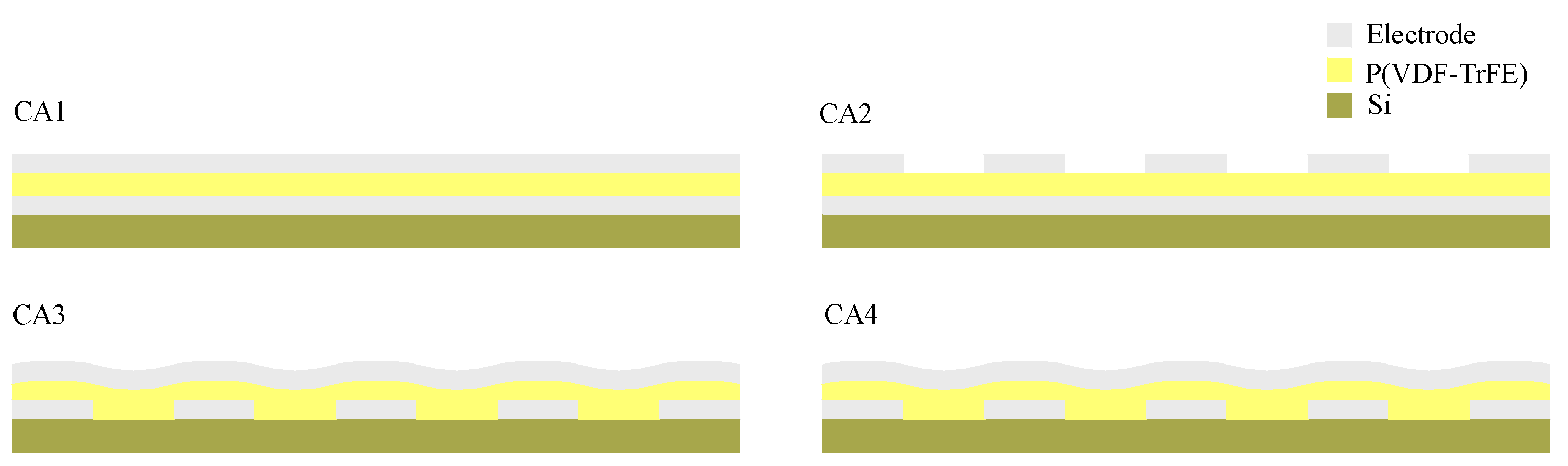
2. Materials and Methods

For metal-ferroelectric-metal capacitor devices with P(VDF-TrFE) ultrathin films, we used a set of four model cells where the effects of different structure patterning could be studied systematically. These cells are called a Crosspoint Array electrode (CA1–4) and have the following combinations of flat and line electrodes, as shown in Figure 1. The top and bottom metal electrodes are fabricated in two different ways: (1) For the top flat electrode, Ti (60 nm) is directly deposited on the P(VDF-TrFE) surface, while for the bottom flat electrode, the silicon wafer is covered globally with Ti; (2) A line electrode can be used as the top or bottom electrode, which is evaporated with a shadow mask, and the width and spacing of the line electrodes are both 250 nm. The thickness of the ferroelectric polymer films of CA1, CA2 is 76 nm, and that of CA3, CA4 is both 57 nm, where the thickness of the film is the distance between the bottom and top electrodes.
The ultrathin films of P(VDF-TrFE) copolymer with mole ratio of VDF-TrFE 70/30 were deposited on silicon wafer by a spin-coating technique from a 2 wt % diethyl carbonate solution at 25 °C. The P(VDF-TrFE) copolymer was provided by Kunshan Hisense Electronic Co., Ltd. (Suzhou, China). The film thickness was measured by Alpha-step 500 surface profiler. The bottom electrodes were fabricated on a 50 nm-thick SiO2 substrate. The P(VDF-TrFE) solution was filtered in advance using 0.1-μm filters. The operating temperature and frequency were 25 °C and 10 Hz, respectively. The samples were then annealed at 130 °C for 1 h. The ferroelectric measurements were obtained on Precision Pro Ferroelectric tester manufactured by Radiant Technologies (Albuquerque, NM, USA).
Figure 2 shows that the polarization increases with the voltage. For the sample of 130 °C annealing, it exhibits a polarization of 9.3 μC/cm2. The polarization enhancement was observed previously, where it might be due to anneal-affected crystallization. In all our reports [29] there is an apparent correlation between the polarization enhancement. The inset shows the CA2 sample AFM (Atomic Force Microscopy) image of a 76-nm P(VDF-TrFE) film spin-coated from DEC (Diethyl Carbonate) solutions. From the inset, it can be seen that the surface is flatter, and grains with a size of 1~2 μm are shown. Worm-like grains are observed and the crystallite regions are assumed to be in the form of lamellae, as is common in polymers.

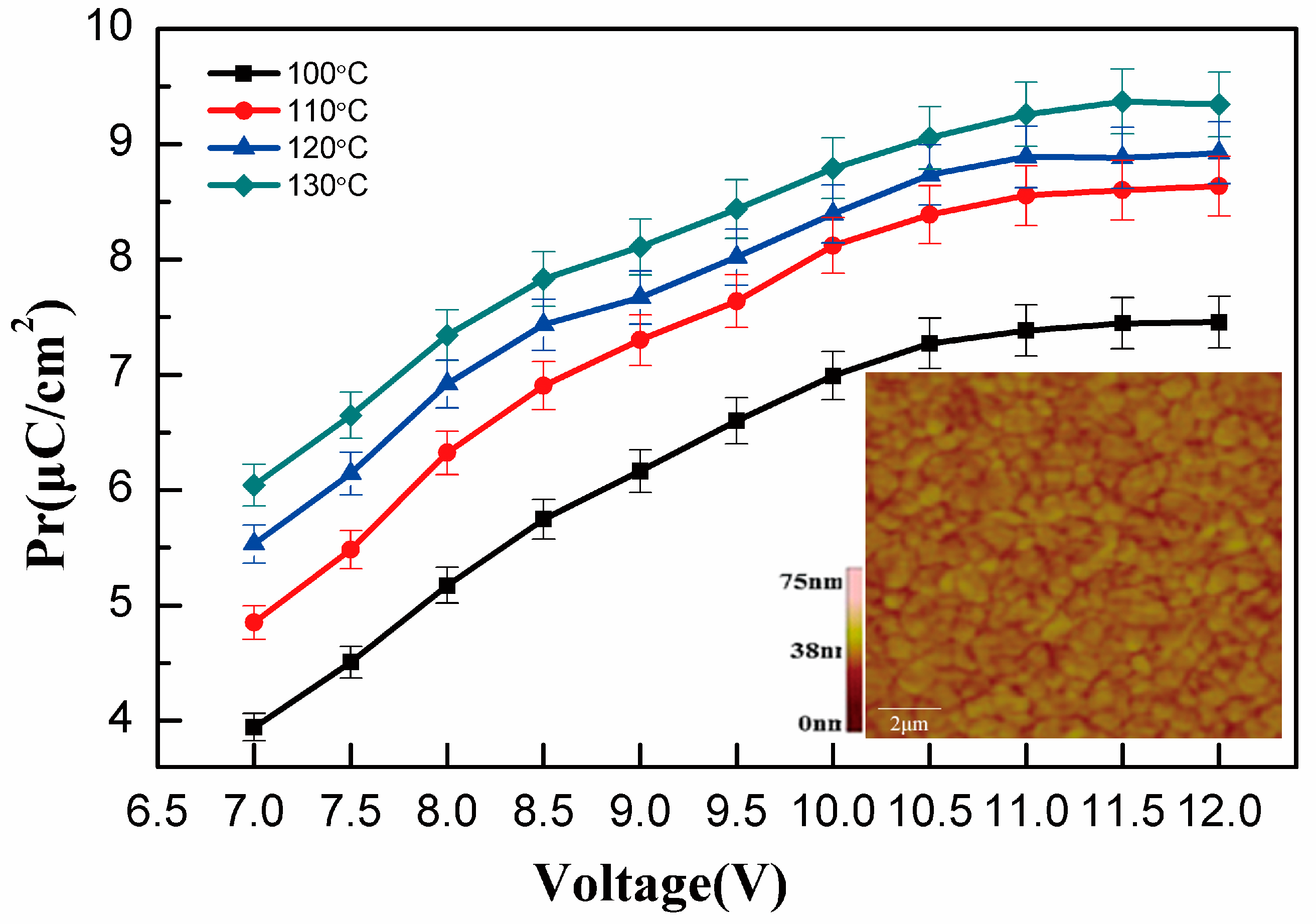
3. Results and Discussion
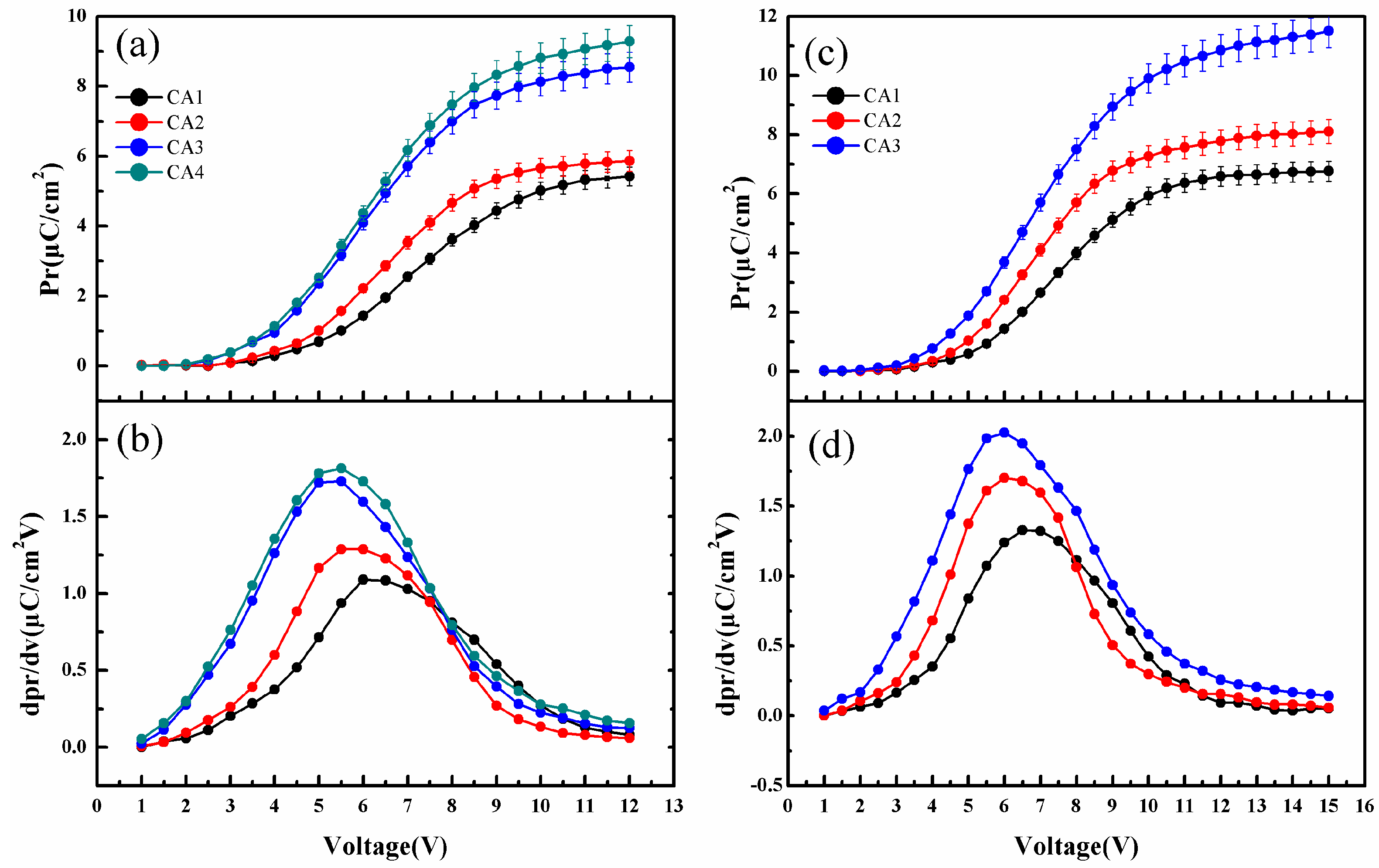
3.1. Polarization

Figure 3a,c show the value of Pr (remanent polarization) measured from drive voltage on the films from 1 V to 12 V and 1 V to 15 V, respectively. A typical “S” shaped curve due to ferroelectric properties is observed for all samples [38]. The first derivative value of Pr as a function of voltage is shown in Figure 3b,d. The samples of CA3 and CA4 with 250-nm spacing line bottom electrodes have the highest value of Pr, and the maximum values of Pr are 8.5 μC/cm2, 9.3 μC/cm2, respectively. The first derivative extreme value of Pr gives the distinct voltage at 5 V and 6 V. On the other hand, the samples of CA1 and CA2 with normal flat bottom electrodes are known for relatively low polarization. However, for the line top electrode of CA2, the polarization performance is improved compared to the flat top electrode of CA1. The maximum Pr values of CA1 and CA2 are 5.4 μC/cm2 and 5.8 μC/cm2, respectively. From these traits, the polarization difference can be attributed to two aspects: the block layer structure effect and the line bottom electrode structure effect.
Figure 4a gives a model of this ferroelectric capacitor, which includes an active layer and a block dead layer. During the top metal electrode evaporation process, the chemical reaction between the Ti electrode and the polymer film results in the formation of a block dead layer. In principle, there could be such a block dead layer between the electrode and the P(VDF-TrFE) film. Many references show the presence of a block dead layer in addition to the active layer in the ferroelectric film capacitor structure [36,39,40,41]. Our previous XPS (X-ray photoelectron spectroscopy) results also clearly revealed the formation of TiFx during the top electrode deposition [27]. It is generally accepted that the polarization in an active layer originates from electric dipoles orientation, which gives rise to a depolarization field (Edep). However, Edep in ferroelectric capacitors can cause a marked effect on polarization values. The design of electronic devices using ferroelectric film capacitors should take into account the effects of Edep. C. T. Black [42] used a ferroelectric capacitor in series with a linear capacitance to simulate the effect of Edep on polarization. The value of Edep is adjusted by changing the amount of compensating charge, which is presented in the following equation:
P r = P r * 1 1 + δ
where Pr* is the maximum value of the ferroelectric polarization when complete charge compensation (δ = 0) occurs in the ferroelectric capacitor. Here δ is used to characterize the effect of Edep. A large δ means that Edep causes significant suppression of the polarization. Without any compensating charge, δ = 4.7 and polarization will be reduced to roughly 18% of the maximum value [42]. Therefore, to stabilize the polarization, one needs to supply compensation charges at the surfaces of the material, because compensation charges weaken the inhibitory effect of the depolarization field [24,43].
In Figure 4b,c, the models of the charge compensation mechanism for the depolarization field are proposed. It can be seen that the block dead layer and free charges are both in existence in these models. The electrons originating from the electrodes nearby could supply the amount of charges needed for the compensation of the ferroelectric dipoles to stabilize the domain during the switching process [36]. However, the different δ is obtained due to the difference of electrode structures. As shown in Figure 4b, for the cells without line electrodes, the ferroelectric active layer is covered by a block dead layer with a large area. What is more, a small number of free charges exist in the ferroelectric thin film surface, and can hardly get through the block dead layer. Therefore, the depolarization field in an active layer cannot be completely compensated by the free charges, which leads to a relatively high δ1. A schematic depiction of the charge compensation mechanism with a line electrode for the depolarization field is presented in Figure 4c. The contact area between the line electrode and polymer is much smaller than that of the flat electrode and polymer owing to the effect of line electrodes spacing, indicating that the ferroelectric active layer is covered by a block dead layer with a relatively small area. A large number of free charges exist in the ferroelectric thin film surface, and can easily get through the block dead layer. Thus, the depolarization field in an active layer is compensated more by a large number of free charges, which leads to a low δ2. The inhibition effect of the depolarization field to ferroelectric thin film polarization is decreased. When δ1 > δ2, Pr1 (without a line electrode) is smaller than Pr2 (with a line electrode). Therefore, the polarization property of ferroelectric thin films with a line electrode is improved.
On the other hand, compared to the effect of the block dead layer, the effect of the line bottom electrode structure is more interesting for the polarization. As shown in Figure 3a, the cells (CA3, CA4) with line bottom electrodes exhibit better polarization than those (CA1, CA2) with normal flat bottom electrodes, which may be attributed to the effect of the line bottom electrode structure. To obtain further insights on the effect of the line bottom electrode structure, the cells with different electrode step heights were prepared (see Section 3.4). However, it is indicated that the effect of the line bottom electrode structure is independent on electrode step heights, and further line bottom electrode mechanistic studies as well as the development of related processes are ongoing in our laboratory.

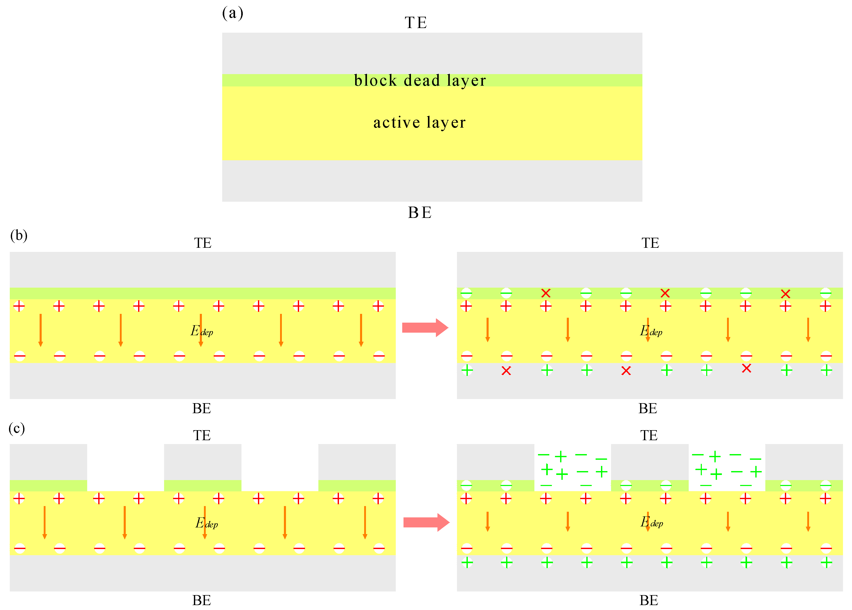
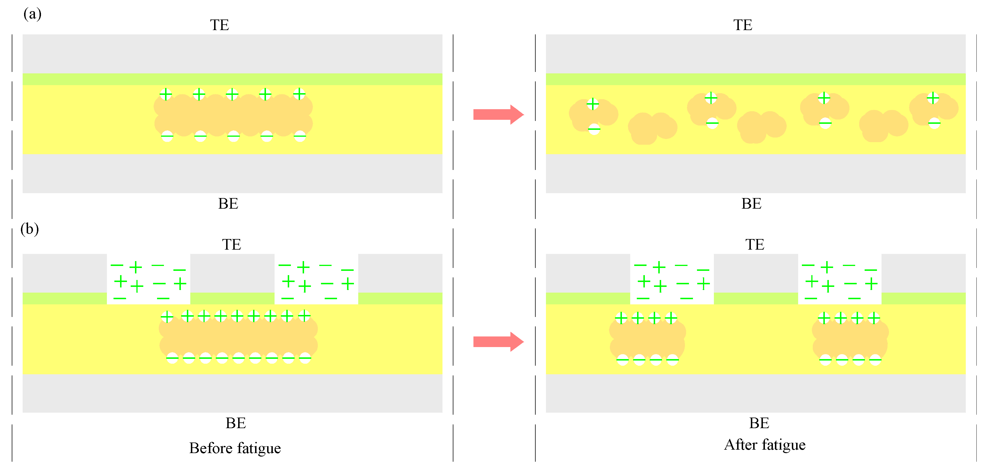
3.2. Effect of Electrode Structure on Fatigue

Table 1 shows the Pr before (BF) and after (AF) fatigue test with different electrode structures, before and after 106 switching cycles. It is clear that the electrode structure effect exists in this system. For the sample of CA4 with line top and bottom electrodes, the Pr is as high as 6.90 μC/cm2 and the value of the fatigue ratio (AF/BF) is at a high level of 0.79 under 106 switching cycles. Therefore, the sample of CA3 with flat top and line bottom electrodes maintains the same Pr value as CA4, but a worse fatigue ratio. However, the value of Pr (4.65 μC/cm2) and the ratio (AF/BF) (0.44) of the CA1 sample with flat top and bottom electrodes are lower than those of the CA4 sample (6.90 μC/cm2, 0.79), with line top and bottom electrodes. Correspondingly, for CA2, which is prepared with line top and flat bottom electrodes. The Pr and ratio (AF/BF) also decrease to 5.02 μC/cm2 and 0.67, respectively,
Thereby, the effect of electrode structure is clearly demonstrated based on different CA cell models. Firstly, the line structure can improve ferroelectric performance due to the charge compensation mechanism in the activation layer. Our previous reports showed that the influence of compensating free charge is one of important factors to improve ferroelectric fatigue [27]. The line electrodes tend to supply more compensating charges between the polymer and electrode layer. This is in accordance with the results shown in Figure 3. Secondly, as the line electrode is prepared as a top/bottom electrode (CA2, CA3), better performance (polarization or fatigue) could be achieved in comparison to the cell with only flat electrodes (CA1). Finally, to further demonstrate the superiority of the line electrode structure, we used line electrodes as bottom and top electrodes. The Pr and ratio (AF/BF) of Table 1 show that in all the fatigued capacitor test results, the sample of CA4 (with top and bottom line electrodes) exhibited excellent ferroelectric performance and fatigue resistance.
As is well-known, the fatigue of the domain occurs in the process of ferroelectric reversal. To understand the mechanism of the ferroelectric polymer domain fatigue, the schematic depiction of domain fatigue is presented in Figure 5. Fatigue in organic ferroelectric materials has been ascribed to charge trapping. Injected charges become trapped at crystalline boundaries and defects, thereby locking the domain walls and reducing the polarization [44]. Here we systematically describe the process of fatigue from the viewpoint of domain degradation. The models start with the assumption that only in an ideal case is the original state homogeneous and in a single domain. As shown in Figure 5a, the schematic of domain deterioration with the flat electrode structure is displayed. It can be seen that the ferroelectric domain is a large-volume single domain and has strong activity before fatigue, after more than 1 × 10⁶ of switching cycles; however, the ferroelectric domain is decomposed from a single domain into many small volumes and the balance of the switching domain is destroyed. On the other hand, the activity of the ferroelectric domain also decreases. In comparison to the flat electrode structure, the deterioration of the ferroelectric domain also occurs in line electrode structure P(VDF-TrFE) film capacitors. However, this deterioration can be weakened by the use of the line electrode structure, as shown in Figure 5b, where it can be seen that a large number of available free charges exist in the P(VDF-TrFE) film active layer surface or interior. With enough charge concentration, ferroelectric domains are usually surrounded by the free charges in the switching progress, which often keep domains alive, especially to maintain domain balance. Therefore, the deterioration and activity reduction of domain are both improved in the switching process. The cell with the line electrode structure exhibited higher remnant polarization and an enhancement of fatigue resistance compared to the other without the line electrode structure, which may be attributed to line electrode effect.

3.3. Effect of Electrode Structure on Driving Voltage

The choice of driving voltage (Vd) is also one of the important factors for the performance of ferroelectric thin films. The device will not work properly if the voltage applied is too small, and may break if the voltage is too large. For example, as shown in Figure 3c, with the increase of voltage, CA4 is broken by the 15-V driving voltage. Therefore, the driving voltage data of CA4 is lacking in Figure 3c, indicating that it is necessary to choose the right voltage. The driving voltage data of cells with different electrode structures are presented in Table 2, which is based on normal speed-functionality drive choice. From the table, it can be seen that in all test results, CA1 with flat top and bottom electrodes requires the highest driving voltage (10.1 V). On the contrary, the lowest Vd (9.3 V) is observed in CA4, with line top and bottom electrodes. In addition, the driving voltage of CA2 and CA3 are 9.8 V and 9.6 V, respectively.
Compared to CA1, the driving voltage of CA2 and CA3 with a line top or bottom electrode decreases by 0.3 V and 0.5 V, respectively. What is more, the driving voltage of CA4 reduces by 0.8 V. This demonstrates, once more, that the electrode structure effects are real in this system. On the basis of the analysis in Section 3.1, owing to the electrode structure effects, the cells with line electrodes (top or bottom) have satisfactory ability to resist fatigue and depolarization field. The larger the depolarization field, the greater the driving voltage required. Therefore, a relatively small voltage (9.3 V) is required for CA4, and a relatively big voltage (10.1 V) is needed for CA1.

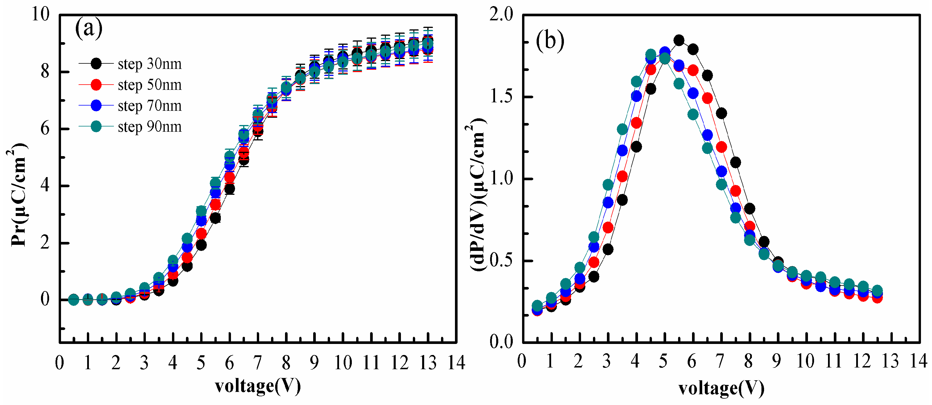
3.4. Polarization Independence of the Electrode Step Heights

In order to further investigate the effect of the line bottom electrode structure, cells with different electrode step heights were prepared. Pr and the first derivative value of Pr as a function of voltage are displayed in Figure 6. As can be seen in Figure 6a, one salient feature of the data is that the Pr curves still show the typical “S” shape, in accordance with Figure 3a. What is more interesting is the result of Pr. Although the cells have different electrode step heights, very similar Pr values are obtained. This suggests that the effect of the line bottom electrode structure is independent of electrode step heights. On the other hand, as shown in Figure 6b, the electrode step heights are 30 nm, 50 nm, 70 nm, and 90 nm, and the voltage of the first derivative extreme values are 6 V, 6 V, 5 V, and 5 V, respectively. The different voltage values are recorded at extremes due to the diversity of the electrode step heights.

4. Conclusions

In summary, we observed a critical dependence of the properties of P(VDF-TrFE) ferroelectric films on the electrode structure. The difference of ferroelectricity could be induced by the line and flat electrode structures. Furthermore, we investigated the cells with line electrodes and observed better polarization and fatigue resistance in comparison to cells with flat electrodes. The analyses presented indicate that the electrode structure effects, including the effect of the block dead layer and line bottom electrode structure effect, are mainly responsible for the performance of the ferroelectric in this system. The switching characteristics are strongly affected by electrode structure factors and the model of free charge compensation mechanism is proposed to explain this effect. The free charges have influence on the depolarization field as well as the domain balance, which is induced by the electrode structure effect. Furthermore, the optimum driving voltage of ferroelectric capacitors with different electrode structures are obtained. These findings provide an effective way to achieve the excellent performance of P(VDF-TrFE) ferroelectric film capacitors.

Acknowledgments

This work was supported by National Natural Science Foundation of China (Contract No. 51503121) and the program of foreign visiting studies of teachers in Shanghai colleges and universities.

Author Contributions

Xiuli Zhang designed the experiments; Long Li, Xiuli Zhang and Haisheng Xu performed the experiments; Long Li, Xiaohui Sun, and Haidong Yuan analyzed the data; Xiuli Zhang and Long Li wrote the paper; Hongzhen Chen revised English grammar.

Conflicts of Interest

The authors declare no conflict of interest.

References

  1. Xu, H.; Fang, X.; Liu, X.; Wu, S.; Gu, Y.; Meng, X.; Sun, J.; Chu, J. Fabrication and properties of solution processed all polymer thin-film ferroelectric device. J. Appl. Polym. Sci. 2011, 120, 1510–1513. [Google Scholar] [CrossRef]
  2. Zhang, X.; Du, X.; Liu, C.; Ji, X.; Xu, H. High temperature-dependent imprint and switching mechanism of poly(vinylidene fluoride-trifluoroethylene) copolymer ultrathin films with electroactive interlayers. Appl. Phys. Lett. 2015, 106, 022906. [Google Scholar] [CrossRef]
  3. Naber, R.C.G.; Blom, P.W.M.; Marsman, A.W.; de Leeuw, D.M. Low voltage switching of a spin cast ferroelectric polymer. Appl. Phys. Lett. 2004, 85, 2032–2034. [Google Scholar] [CrossRef]
  4. Fujisaki, S.; Ishiwara, H.; Fujisaki, Y. Low-voltage operation of ferroelectric poly(vinylidene fluoride-trifluoroethylene) copolymer capacitors and metal-ferroelectric-insulator-semiconductor diodes. Appl. Phys. Lett. 2007, 90, 162902. [Google Scholar] [CrossRef]
  5. Naber, R.C.G.; de Boer, B.; Blom, P.W.M.; de Leeuw, D.M. Low-voltage polymer field-effect transistors for nonvolatile memories. Appl. Phys. Lett. 2005, 87, 203509. [Google Scholar] [CrossRef]
  6. Bae, S.H.; Kahya, O.; Sharma, B.K.; Kwon, J.; Cho, H.J.; Özyilmaz, B.; Ahn, J.H. Graphene-P(VDF-TrFE) multilayer film for flexible applications. ACS Nano 2013, 7, 3130–3138. [Google Scholar] [CrossRef] [PubMed]
  7. Martins, P.; Lasheras, A.; Gutierrez, J.; Barandiaran, J.M.; Orue, I.; Lanceros-Mendez, S. Optimizing piezoelectric and magnetoelectric responses on CoFe2O4/P(VDF-TrFE) nanocomposites. J. Phys. D Appl. Phys. 2011, 44, 495303. [Google Scholar] [CrossRef]
  8. Zhang, X.; Dong, W.; Liu, Y.; Xu, G.; Xu, H. Structural and ferroelectric behaviours in blends of vinylidene fluoride oligomer and poly(vinylidene fluoride-trifluoroethylene) copolymer thin film. J. Phys. D Appl. Phys. 2011, 44, 435304. [Google Scholar] [CrossRef]
  9. Mai, M.; Ke, S.; Lin, P.; Zeng, X. Ferroelectric polymer thin films for organic electronics. J. Nanomater. 2015, 2015, 1–14. [Google Scholar] [CrossRef]
  10. Hu, W.J.; Juo, D.M.; You, L.; Wang, J.; Chen, Y.C.; Chu, Y.H.; Wu, T. Universal ferroelectric switching dynamics of vinylidene fluoride-trifluoroethylene copolymer films. Sci. Rep. 2014, 4, 4772. [Google Scholar] [CrossRef] [PubMed]
  11. Hou, Y.; Zhang, X.; Zhang, Y.; Xu, G.; Xu, H. High-temperature ferroelectric behaviors of poly(vinylidene fluoride-trifluoroethylene) copolymer ultrathin films with electroactive interlayers. J. Appl. Phys. 2012, 111, 064506. [Google Scholar] [CrossRef]
  12. Won, S.S.; Sheldon, M.; Mostovych, N.; Kwak, J.; Chang, B.-S.; Ahn, C.W.; Kingon, A.I.; Kim, I.W.; Kim, S.-H. Piezoelectric poly(vinylidene fluoride trifluoroethylene) thin film-based power generators using paper substrates for wearable device applications. Appl. Phys. Lett. 2015, 107, 202901. [Google Scholar] [CrossRef]
  13. Mathur, S.C.; Scheinbeim, J.I.; Newman, B.A. Piezoelectric properties and ferroelectric hysteresis effects in uniaxially stretched nylon-11 films. J. Appl. Phys. 1984, 56, 2419–2425. [Google Scholar] [CrossRef]
  14. Kawai, H. The piezoelectricity of poly(vinylidene fluoride). Jpn. J. Appl. Phys. 2014, 8, 975–976. [Google Scholar] [CrossRef]
  15. Pratap, A.; Joshi, N.J.; Rakshit, P.B.; Grewal, G.S.; Shrinet, V. Dielectric behavior of nano barium titanate filled polymeric composites. Int. J. Mod. Phys. Conf. Ser. 2013, 22, 1–10. [Google Scholar] [CrossRef]
  16. Xu, H. Dielectric properties and ferroelectric behavior of poly(vinylidene fluoride-trifluoroethylene) 50/50 copolymer ultrathin films. J. Appl. Polym. Sci. 2001, 80, 2259–2266. [Google Scholar] [CrossRef]
  17. Chen, S.; Yao, K.; Tay, F.E.H.; Chew, L.L.S. Comparative investigation of the structure and properties of ferroelectric poly(vinylidene fluoride) and poly(vinylidene fluoride-trifluoroethylene) thin films crystallized on substrates. J. Appl. Polym. Sci. 2010. [Google Scholar] [CrossRef]
  18. Yamada, T.; Kitayama, T. Ferroelectric properties of vinylidene fluoride-trifluoroethylene copolymers. J. Appl. Phys. 1981, 52, 6859–6863. [Google Scholar] [CrossRef]
  19. Mahdi, R.I.; Gan, W.C.; Abd Majid, W.H. Hot plate annealing at a low temperature of a thin ferroelectric P(VDF-TrFE) film with an improved crystalline structure for sensors and actuators. Sensors 2014, 14, 19115–19127. [Google Scholar] [CrossRef] [PubMed]
  20. Park, J.-M.; Kong, J.-W.; Kim, D.-S.; Yoon, D.-J. Nondestructive damage detection and interfacial evaluation of single-fibers/epoxy composites using PZT, PVDF and P(VDF-TrFE) copolymer sensors. Compos. Sci. Technol. 2005, 65, 241–256. [Google Scholar] [CrossRef]
  21. Mandal, D.; Yoon, S.; Kim, K.J. Origin of piezoelectricity in an electrospun poly(vinylidene fluoride-trifluoroethylene) nanofiber web-based nanogenerator and nano-pressure sensor. Macromol. Rapid Commun. 2011, 32, 831–837. [Google Scholar] [CrossRef] [PubMed]
  22. Zhang, Q.M.; Li, H.; Poh, M.; Xia, F.; Cheng, Z.Y.; Xu, H.; Huang, C. An all-organic composite actuator material with a high dielectric constant. Nature 2002, 419, 284–287. [Google Scholar] [CrossRef] [PubMed]
  23. Asadi, K.; de Leeuw, D.M.; de Boer, B.; Blom, P.W. Organic non-volatile memories from ferroelectric phase-separated blends. Nat. Mater. 2008, 7, 547–550. [Google Scholar] [CrossRef] [PubMed]
  24. Naber, R.C.; Asadi, K.; Blom, P.W.; de Leeuw, D.M.; de Boer, B. Organic nonvolatile memory devices based on ferroelectricity. Adv. Mater. 2010, 22, 933–945. [Google Scholar] [CrossRef] [PubMed]
  25. Hu, Z.; Tian, M.; Nysten, B.; Jonas, A.M. Regular arrays of highly ordered ferroelectric polymer nanostructures for non-volatile low-voltage memories. Nat. Mater. 2009, 8, 62–67. [Google Scholar] [CrossRef] [PubMed]
  26. Mao, D.; Mejia, I.; Stiegler, H.; Gnade, B.E.; Quevedo-Lopez, M.A. Polarization behavior of poly(vinylidene fluoride-trifluoroethylene) copolymer ferroelectric thin film capacitors for nonvolatile memory application in flexible electronics. J. Appl. Phys. 2010, 108, 094102. [Google Scholar] [CrossRef]
  27. Xu, H.; Liu, X.; Fang, X.; Xie, H.; Li, G.; Meng, X.; Sun, J.; Chu, J. Domain stabilization effect of interlayer on ferroelectric poly(vinylidene fluoride-trifluoroethylene) copolymer ultrathin film. J. Appl. Phys. 2009, 105, 22. [Google Scholar] [CrossRef]
  28. Xia, F.; Xu, H.; Fang, F.; Razavi, B.; Cheng, Z.Y.; Lu, Y.; Xu, B.; Zhang, Q.M. Thickness dependence of ferroelectric polarization switching in poly(vinylidene fluoride–trifluoroethylene) spin cast films. Appl. Phys. Lett. 2001, 78, 1122–1124. [Google Scholar] [CrossRef]
  29. Du, X.; Zhao, M.; Chen, G.; Zhang, X. Thickness dependence of ferroelectric properties for ferroelectric random access memory based on poly(vinylidene fluoride-trifluoroethylene) ultrathin films. Ferroelectrics 2015, 488, 148–153. [Google Scholar] [CrossRef]
  30. Furukawa, T. Ferroelectric properties of vinylidene fluoride copolymers. Phase Transit. 1989, 18, 143–211. [Google Scholar] [CrossRef]
  31. Singh, D.; Deepak, A.G. Cooling rate controlled microstructure evolution and reduced coercivity in P(VDF-TrFE) devices for memory applications. Org. Electron. 2014, 15, 82–90. [Google Scholar] [CrossRef]
  32. Furukawa, T. Structure and functional properties of ferroelectric polymers. Key Eng. Mater. 1994, 92–93, 15–30. [Google Scholar] [CrossRef]
  33. Onishi, S.; Hamada, K.; Ishihara, K.; Ito, Y. A half-micron ferroelectric memory cell technology with stacked capacitor structure. In Proceedings of the 1994 IEEE International Electron Devices Meeting, San Francisco, CA, USA, 11–14 December 1994; pp. 843–846. [Google Scholar]
  34. Subash, C.K.; Valiyaneerilakkal, U.; Singh, K.; Varghese, S. Device level optimization of poly(vinylidene fluoride-trifluoroethylene)-zinc oxide polymer nanocomposite thin films for ferroelectric applications. J. Appl. Phys. 2015, 118, 204102. [Google Scholar]
  35. Hou, Y.; Lü, Z.; Pu, T.; Zhang, Y.; Xu, G.; Xu, H. Fast switching protocol for ferroelectric random access memory based on poly(vinylidene fluoride-trifluoroethylene) copolymer ultrathin films. Appl. Phys. Lett. 2013, 102, 063507. [Google Scholar] [CrossRef]
  36. Zhang, X.; Hou, Y.; Zhang, Y.; Lv, Z.; Xu, G.; Xu, H. The effect of electroactive interlayer on the ferroelectric properties in poly(vinylidene fluoride-trifluoroethylene) copolymer ultrathin films. J. Appl. Phys. 2012, 112, 074111. [Google Scholar] [CrossRef]
  37. Genc, R.; Alas, M.O.; Harputlu, E.; Repp, S.; Kremer, N.; Castellano, M.; Colak, S.G.; Ocakoglu, K.; Erdem, E. High-capacitance hybrid supercapacitor based on multi-colored fluorescent carbon-dots. Sci. Rep. 2017, 7, 11222. [Google Scholar] [CrossRef] [PubMed]
  38. Larsen, P.K.; Dormans, G.J.M.; Taylor, D.J.; van Veldhoven, P.J. Ferroelectric properties and fatigue of PbZr051Ti0.49O3 thin films of varying thickness: Blocking layer model. J. Appl. Phys. 1994, 76, 2405–2413. [Google Scholar]
  39. Jiang, A.Q.; Lin, Y.Y.; Tang, T.A. Charge injection and polarization fatigue in ferroelectric thin films. J. Appl. Phys. 2007, 102, 074109. [Google Scholar] [CrossRef]
  40. Yang, Q.; Cao, J.; Zhou, Y.; Sun, L.; Lou, X. Dead layer effect and its elimination in ferroelectric thin film with oxide electrodes. Acta Mater. 2016, 112, 216–223. [Google Scholar] [CrossRef]
  41. Bratkovsky, A.M.; Levanyuk, A.P. Very large dielectric response of thin ferroelectric films with the dead layers. Phys. Rev. B 2001, 63. [Google Scholar] [CrossRef]
  42. Black, C.T.; Farrell, C.; Licata, T.J. Suppression of ferroelectric polarization by an adjustable depolarization field. Appl. Phys. Lett. 1997, 71, 2041–2043. [Google Scholar] [CrossRef]
  43. Wurfel, P.; Batra, I.P. Depolarization-field-induced instability in thin ferroelectric films—Experiment and theory. Phys. Rev. B 1973, 8, 5126–5133. [Google Scholar] [CrossRef]
  44. Zhu, G.; Gu, Y.; Yu, H.; Fu, S.; Jiang, Y. Polarization fatigue in ferroelectric vinylidene fluoride and trifluoroethylene copolymer thin films. J. Appl. Phys. 2011, 110, 024109. [Google Scholar] [CrossRef]
Figure 1. The scheme depiction of capacitor with different electrode structures. (CA1) Flat-flat capacitor with flat top and bottom electrode structure. (CA2) Line-flat capacitor with line top and flat bottom electrode structure. (CA3) Flat-line capacitor with flat top and line bottom electrode structure. (CA4) Line-line capacitor with line top and bottom electrodes perpendicular to each other.
Polymers 10 00006 g001
Figure 2. The Pr as a function of driver voltage from 7 V to 12 V at different anneal temperatures (100–130 °C). The inset shows CA2 sample AFM (Atomic Force Microscopy) images of a 76-nm P(VDF-TrFE) film.
Polymers 10 00006 g002
Figure 3. Pr and the first derivative value of Pr. (a) Pr as a function of the driver voltage from 1 V to 12 V; (b) The first derivative value of Pr with the driver voltage from 1 V to 12 V; (c) Pr as a function of the driver voltage from 1 V to 15 V; (d) The first derivative value of Pr with the driver voltage from 1 V to 15 V.
Polymers 10 00006 g003
Figure 4. (a) Model of the ferroelectric capacitor with a P(VDF-TrFE) film including an active layer and a block dead layer. The top and bottom electrodes are indicated by TE and BE, respectively. (b) The model of charge compensation mechanism with a flat electrode for the depolarization field. (c) The model of charge compensation mechanism with a line electrode for the depolarization field.
Polymers 10 00006 g004
Figure 5. Schematic of polarization reversal fatigue progress. (a) Schematic of domain degradation progress without enough free charges; (b) Schematic of domain degradation progress with enough free charges.
Polymers 10 00006 g005
Figure 6. Pr and the first derivative value of Pr. (a) Pr as a function of the driver voltage for the films with varying step heights; (b) The first derivative value as a function of voltage for the films with varying step heights.
Polymers 10 00006 g006
Table 1. Pr before (BF) and after (AF) fatigue test with different electrode structures.
Cell nameCA1CA2CA3CA4
Top electrodeFlatLineFlatLine
Bottom electrodeFlatFlatLineLine
Pr(BF) (μC/cm2)4.655.026.936.90
Pr(AF) (μC/cm2)2.983.403.805.43
Ratio (AF/BF)0.440.670.560.79
Table 2. Driving voltage test result with different electrode structures.
Cell nameCA1CA2CA3CA4
Vd10.1 V9.8 V9.6 V9.3 V

