Inverted Organic Solar Cells with Low-Temperature Al-Doped-ZnO Electron Transport Layer Processed from Aqueous Solution

 ,
,
Abstract
:
1. Introduction
2. Materials and Methods
2.1. Materials
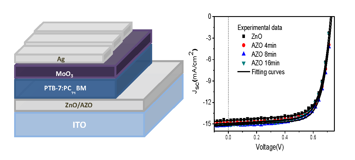
2.2. Film Formation and Inverted Solar Cells Fabrication
2.3. Device Characterization
3. Results and Discussion
4. Conclusions
Acknowledgments
Author Contributions
Conflicts of Interest
References
- Krebs, F.C.; Nielsen, T.D.; Fyenbo, J.; Wadstrøm, M.; Pedersen, M.S. Manufacture, integration and demonstration of polymer solar cells in a lamp for the “Lighting Africa” initiative. Energy Environ. Sci. 2010, 3, 512–525. [Google Scholar] [CrossRef]
- Liang, Y.; Yu, L. A New Class of Semiconducting Polymers for Bulk Heterojunction Solar Cells with Exceptionally High Performance. Acc. Chem. Res. 2010, 43, 1227–1236. [Google Scholar] [CrossRef] [PubMed]
- Wang, T.; Scarratt, N.W.; Yi, H.; Dunbar, A.D.F.; Pearson, A.J.; Watters, D.C.; Glen, T.S.; Brook, A.C.; Kingsley, J.; Buckley, A.R.; et al. Fabricating High Performance, Donor-Acceptor Copolymer Solar Cells by Spray-Coating in Air. Adv. Energy Mater. 2013, 3, 505–512. [Google Scholar] [CrossRef]
- Li, N.; Baran, D.; Spyropoulos, G.D.; Zhang, H.; Berny, S.; Turbiez, M.; Ameri, T.; Krebs, F.C.; Brabec, C.J. Environmentally Printing Efficient Organic Tandem Solar Cells with High Fill Factors: A Guideline Towards 20% Power Conversion Efficiency. Adv. Energy Mater. 2014, 4, 1400084. [Google Scholar] [CrossRef]
- Lin, Z.; Chang, J.; Zhang, J.; Jiang, C.; Wu, J.; Zhu, C. A work-function tunable polyelectrolyte complex (PEI:PSS) as a cathode interfacial layer for inverted organic solar cells. J. Mater. Chem. A 2014, 2, 7788–7794. [Google Scholar] [CrossRef]
- Lee, B.R.; Lee, S.; Park, J.H.; Jung, E.D.; Yu, J.C.; Nam, Y.S.; Heo, J.; Kim, J.; Kim, B.; Song, M.H. Amine-Based Interfacial Molecules for Inverted Polymer-Based Optoelectronic Devices. Adv. Mater. 2015, 27, 3553–3559. [Google Scholar] [CrossRef] [PubMed]
- Chalal, D.; Garuz, R.; Benachour, D.; Bouclé, J.; Ratier, B. Influence of an electrode self-protective architecture on the stability of inverted polymer solar cells based on P3HT:PCBM with an active area of 2 cm2. Synth. Met. 2016, 212, 161–166. [Google Scholar] [CrossRef]
- Vohra, V.; Kawashima, K.; Kakara, T.; Koganezawa, T.; Osaka, I.; Takimiya, K.; Murata, H. Efficient inverted polymer solar cells employing favourable molecular orientation. Nat. Photon. 2015, 9, 403–408. [Google Scholar] [CrossRef]
- Kan, B.; Zhang, Q.; Li, M.; Wan, X.; Ni, W.; Long, G.; Wang, Y.; Yang, X.; Feng, H.; ChenL, Y. Solution-Processed Organic Solar Cells Based on Dialkylthiol-Substituted Benzodithiophene Unit with Efficiency near 10%. J. Am. Chem. Soc. 2014, 136, 15529–15532. [Google Scholar] [CrossRef] [PubMed]
- Brabec, C.J.; Gowrisanker, S.; Halls, J.J.M.; Laird, D.; Jia, S.; Williams, S.P. Polymer-Fullerene Bulk-Heterojunction Solar Cells. Adv. Mater. 2010, 22, 3839–3856. [Google Scholar] [CrossRef] [PubMed]
- Huang, J.; Li, C.; Chueh, C.; Liu, S.; Yu, J.; Jen, A.K. 10.4% Power Conversion Efficiency of ITO-Free Organic Photovoltaics through Enhanced Light Trapping Configuration. Adv. Energy Mater. 2015, 5, 1500406. [Google Scholar] [CrossRef]
- Nguyen, T.L.; Choi, H.; Ko, S.-J.; Uddin, M.A.; Walker, B.; Yum, S.; Jeong, J.-E.; Yun, M.H.; Shin, T.J.; Hwang, S.; et al. Semi-crystalline photovoltaic polymers with efficiency exceeding 9% in a ∼300 nm thick conventional single-cell device. Energy Environ. Sci. 2014, 7, 3040–3051. [Google Scholar] [CrossRef]
- Ye, L.; Zhao, W.; Li, S.; Mukherjee, S.; Carpenter, J.H.; Awartani, O.; Jiao, X.; Hou, J.; Ade, H. High-Efficiency Nonfullerene Organic Solar Cells: Critical Factors that Affect Complex Multi-Length Scale Morphology and Device Performance. Adv. Energy Mater. 2017, 7, 1602000. [Google Scholar] [CrossRef]
- Zhong, H.; Ye, L.; Chen, J.; Jo, S.B.; Chueh, C.; Carpenter, J.H.; Ade, H.; Jen, A.K.-Y. A regioregular conjugated polymer for high performance thick-film organic solar cells without processing additive. J. Mater. Chem. A 2017, 5, 10517. [Google Scholar] [CrossRef]
- Ye, L.; Zhang, S.; Zhao, W.; Yao, H.; Hou, J. Highly Efficient 2D-Conjugated Benzodithiophene-Based Photovoltaic Polymer with Linear Alkylthio Side Chain. Chem. Mater. 2014, 26, 3603–3605. [Google Scholar] [CrossRef]
- Ye, L.; Jiao, X.; Zhou, M.; Zhang, S.; Yao, H.; Zhao, W.; Xia, A.; Ade, H.; Hou, J. Manipulating Aggregation and Molecular Orientation in All-Polymer Photovoltaic Cells. Adv. Mater. 2015, 27, 6046–6054. [Google Scholar] [CrossRef] [PubMed]
- Li, Y. Molecular Design of Photovoltaic Materials for Polymer Solar Cells: Toward Suitable Electronic Energy Levels and Broad Absorption. Acc. Chem. Res. 2012, 45, 723–733. [Google Scholar] [CrossRef] [PubMed]
- Bin, H.; Gao, L.; Zhang, Z.; Yang, Y.; Zhan, Y.; Zhang, C.; Chen, S.; Xue, L.; Yang, C.; Xiao, M.; et al. 11.4% Efficiency non-fullerene polymer solar cells with trialkylsilyl substituted 2D-conjugated polymer as donor. Nat. Commun. 2016, 7, 13651. [Google Scholar] [CrossRef] [PubMed]
- Zhang, S.; Ye, L.; Hou, J. Breaking the 10% Efficiency Barrier in Organic Photovoltaics: Morphology and Device Optimization of Well-Known PBDTTT Polymers. Adv. Energy Mater. 2016, 6, 1502529. [Google Scholar] [CrossRef]
- Min, J.; Luponosov, Y.N.; Zhang, Z.G.; Ponomarenko, S.A.; Ameri, T.; Li, Y.; Brabec, C.J. Interface Design to Improve the Performance and Stability of Solution-Processed Small-Molecule Conventional Solar Cells. Adv. Energy Mater. 2014, 4, 1400816. [Google Scholar] [CrossRef]
- Stubhan, T.; Litzov, I.; Li, N.; Salinas, M.; Steidl, M.; Sauer, G.; Forberich, K.; Matt, G.J.; Halik, M.; Brabec, C.J. Overcoming interface losses in organic solar cells by applying low temperature, solution processed aluminum-doped zinc oxide electron extraction layers. J. Mater. Chem. A 2013, 1, 6004–6009. [Google Scholar] [CrossRef]
- Norrman, K.; Gevorgyan, S.A.; Krebs, F.C. Water-Induced Degradation of Polymer Solar Cells Studied by H218O Labeling. ACS Appl. Mater. Interfaces 2009, 1, 102–112. [Google Scholar] [CrossRef] [PubMed]
- Kawano, K.; Pacios, R.; Poplavskyy, D.; Nelson, J.; Bradley, D.D.C.; Durrant, J.R. Degradation of organic solar cells due to air exposure. Sol. Energy Mater. Sol. Cells 2006, 90, 3520. [Google Scholar] [CrossRef]
- Sun, Y.; Seo, J.H.; Takacs, C.J.; Seifter, J.; Heeger, A.J. Inverted Polymer Solar Cells Integrated with a Low-Temperature-Annealed Sol-Gel-Derived ZnO Film as an Electron Transport Layer. Adv. Mater. 2011, 23, 1679–1683. [Google Scholar] [CrossRef] [PubMed]
- Sun, Y.; Takacs, C.J.; Cowan, S.R.; Seo, J.H.; Gong, X.; Roy, A.; Heeger, A.J. Efficient, Air-Stable Bulk Heterojunction Polymer Solar Cells Using MoOx as the Anode Interfacial Layer. Adv. Mater. 2011, 23, 2226–2230. [Google Scholar] [CrossRef] [PubMed]
- Krebs, F.C. Polymer solar cell modules prepared using roll-to-roll methods: Knife-over-edge coating, slot-die coating and screen printing. Sol. Energy Mater. Sol. Cells 2009, 93, 465–475. [Google Scholar] [CrossRef]
- He, Z.; Zhong, C.; Su, S.; Xu, M.; Wu, H.; Cao, Y. Enhanced power-conversion efficiency in polymer solar cells using an inverted device structure. Nat. Photon. 2012, 6, 591–595. [Google Scholar] [CrossRef]
- Li, G.; Chu, C.-W.; Shrotriya, V.; Huang, J.; Yang, Y. Efficient inverted polymer solar cells. Appl. Phys. Lett. 2006, 88, 253503. [Google Scholar] [CrossRef]
- Waldauf, C.; Morana, M.; Denk, P.; Schilinsky, P.; Coakley, K.; Choulis, S.A.; Brabec, C.J. Highly efficient inverted organic photovoltaics using solution based titanium oxide as electron selective contact. Appl. Phys. Lett. 2006, 89, 233517. [Google Scholar] [CrossRef]
- Lin, Z.; Jiang, C.; Zhu, C.; Zhang, J. Development of Inverted Organic Solar Cells with TiO2 Interface Layer by Using Low-Temperature Atomic Layer Deposition. ACS Appl. Mater. Interfaces 2013, 5, 713–718. [Google Scholar] [CrossRef] [PubMed]
- Liu, J.; Shao, S.; Meng, B.; Fang, G.; Xie, Z.; Wang, L.; Li, X. Enhancement of inverted polymer solar cells with solution-processed ZnO-TiOX composite as cathode buffer layer. Appl. Phys. Lett. 2012, 100, 213906. [Google Scholar] [CrossRef]
- Cheun, H.; Fuentes-Hernandez, C.; Shim, J.; Fang, Y.; Cai, Y.; Li, H.; Sigdel, A.K.; Meyer, J.; Maibach, J.; Dindar, A.; et al. Oriented Growth of Al2O3:ZnO Nanolaminates for Use as Electron-Selective Electrodes in Inverted Polymer Solar Cells. Adv. Funct. Mater. 2012, 22, 1531–1538. [Google Scholar] [CrossRef]
- Shao, S.; Zheng, K.; Pullerits, T.; Zhang, F. Enhanced Performance of Inverted Polymer Solar Cells by Using Poly(ethylene oxide)-Modified ZnO as an Electron Transport Layer. ACS Appl. Mater. Interfaces 2013, 5, 380–385. [Google Scholar] [CrossRef] [PubMed]
- Lin, Z.; Chang, J.; Zhang, C.; Zhang, J.; Wu, J.; Hao, Y. Low temperature aqueous solution-processed Li doped ZnO buffer layers for high performance inverted organic solar cells. J. Mater. Chem. C 2016, 4, 6169–6175. [Google Scholar] [CrossRef]
- Chang, J.; Lin, Z.; Zhu, C.; Chi, C.; Zhang, J.; Wu, J. Solution-Processed LiF-Doped ZnO Films for High Performance Low Temperature Field Effect Transistors and Inverted Solar Cells. ACS Appl. Mater. Interfaces 2013, 5, 6687–6693. [Google Scholar] [CrossRef] [PubMed]
- Yin, Z.; Zheng, Q.; Chen, S.-C.; Cai, D.; Zhou, L.; Zhang, J. Bandgap Tunable Zn1-xMgxO Thin Films as Highly Transparent Cathode Buffer Layers for High-Performance Inverted Polymer Solar Cells. Adv. Energy Mater. 2014, 4, 1301404. [Google Scholar] [CrossRef]
- Pachoumi, C.; Li, Y.; Vaynzof, K.K.; Banger, H. Sirringhaus. Improved Performance and Stability of Inverted Organic Solar Cells with Sol-Gel Processed, Amorphous Mixed Metal Oxide Electron Extraction Layers Comprising Alkaline Earth Metals. Adv. Energy Mater. 2013, 3, 1428–1436. [Google Scholar] [CrossRef]
- Liang, Z.; Zhang, Q.; Jiang, L.; Cao, G. ZnO cathode buffer layers for inverted polymer solar cells. Energy Environ. Sci. 2015, 8, 3442–3476. [Google Scholar] [CrossRef]
- Zhang, C.; You, H.; Lin, Z.; Hao, Y. Inverted organic photovoltaic cells with solution-processed zinc oxide as electron collecting layer. Jpn. J. Appl. Phys. 2011, 5, 082302. [Google Scholar] [CrossRef]
- Chen, D.; Zhang, C.; Wei, W.; Wang, Z.; Heng, T.; Tang, S.; Han, G.; Zhang, J.; Hao, Y. Stability of inverted organic solar cells with low-temperature ZnO buffer layer processed from aqueous solution. Phys. Status Solidi A 2015, 212, 2262–2270. [Google Scholar] [CrossRef]
- Chen, D.; Zhang, C.; Heng, T.; Wei, W.; Wang, Z.; Han, G.; Feng, Q.; Hao, Y.; Zhang, J. Efficient inverted polymer solar cells using low-temperature zinc oxide interlayer processed from aqueous solution. Jpn. J. Appl. Phys. 2015, 54, 042301. [Google Scholar] [CrossRef]
- Wei, W.; Zhang, C.; Chen, D.; Wang, Z.; Zhu, C.; Zhang, J.; Lu, X.; Hao, Y. Efficient “Light-soaking”-free Inverted Organic Solar Cells with Aqueous Solution Processed Low-Temperature ZnO Electron Extraction Layers. ACS Appl. Mater. Interfaces 2013, 5, 13318–13324. [Google Scholar] [CrossRef] [PubMed]
- You, H.; Zhang, J.; Zhang, C.; Lin, Z.; Chen, D.; Chang, J.; Zhang, J. Efficient flexible inverted small-bandgap organic solar cells with low-temperature zinc oxide interlayer. Jpn. J. Appl. Phys. 2016, 55, 122302. [Google Scholar] [CrossRef]
- You, H.; Zhang, J.; Zhang, Z.; Zhang, C.; Lin, Z.; Chang, J.; Han, G.; Zhang, J.; Lu, G.; Hao, Y. Low Temperature Aqueous Solution-Processed ZnO and Polyethylenimine Ethoxylated Cathode Buffer Bilayer for High Performance Flexible Inverted Organic Solar Cells. Energies 2017, 10, 494. [Google Scholar] [CrossRef]
- Lin, Y.; Thomas, S.R.; Faber, H.; Li, R.; McLachlan, M.A.; Patsalas, P.A.; Anthopoulos, T.D. Al-Doped ZnO Transistors Processed from Solution at 120 °C. Adv. Electron. Mater. 2016, 2, 1600070. [Google Scholar] [CrossRef]
- Zhang, C.; Zhang, J.; Hao, Y.; Lin, Z.; Zhu, C. A simple and efficient solar cell parameter extraction method from a single current-voltage curve. J. Appl. Phys. 2011, 110. [Google Scholar] [CrossRef]
- Chen, M.-H.; Kuo, Y.-C.; Lin, H.-H.; Chao, Y.-P.; Wong, M.-S. Highly stable inverted organic photovoltaics using aluminum-doped zinc oxide as electron transport layers. J. Power Sources 2015, 275, 274–278. [Google Scholar] [CrossRef]


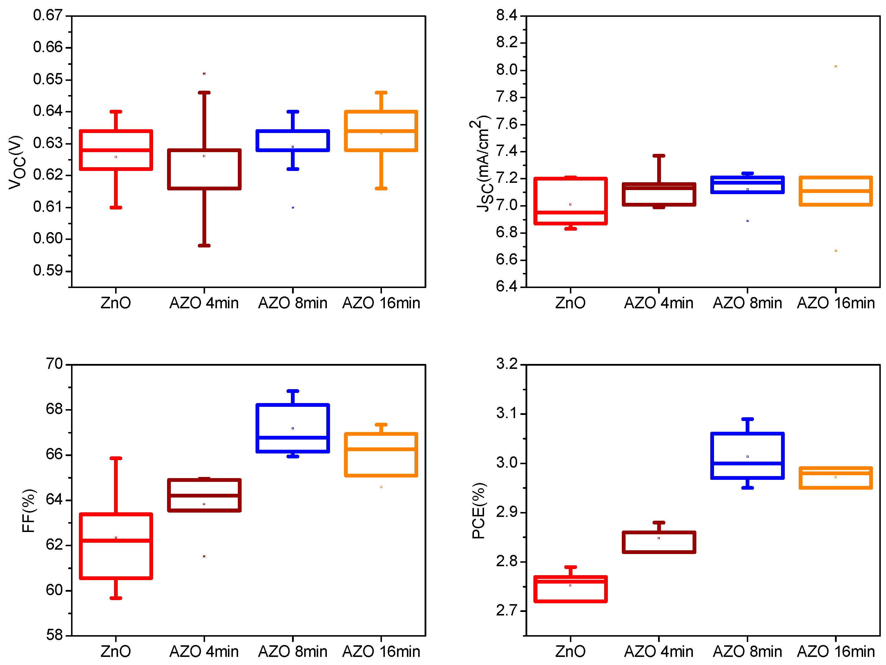
| Device | VOC (V) | JSC (mA/cm2) | FF (%) | PCE (%) |
|---|---|---|---|---|
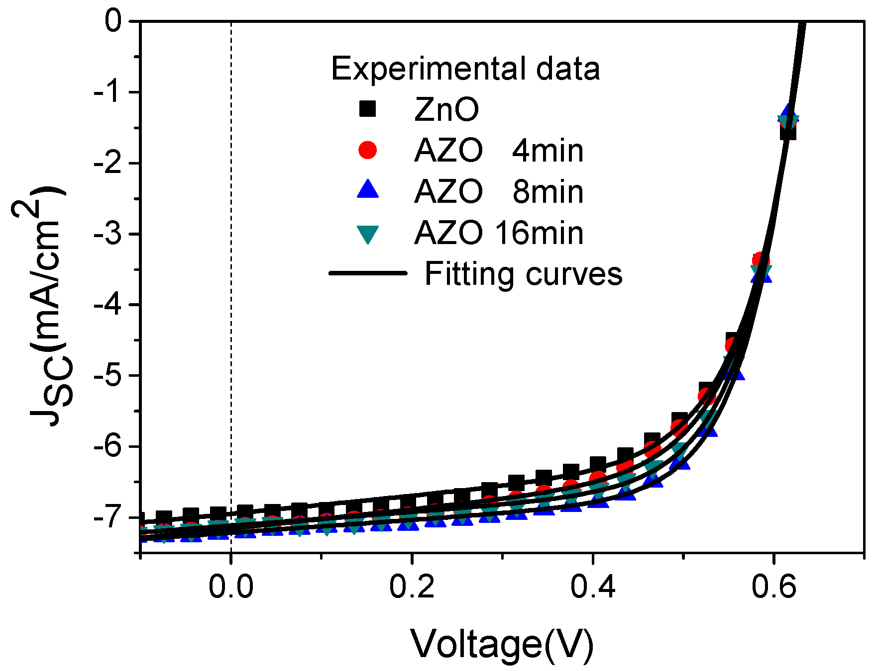
| ZnO | 0.634 | 6.95 | 63.38 | 2.79 |
| AZO 4 min | 0.628 | 7.13 | 64.21 | 2.88 |
| AZO 8 min | 0.628 | 7.21 | 68.21 | 3.09 |
| AZO 16 min | 0.628 | 7.11 | 66.94 | 2.99 |
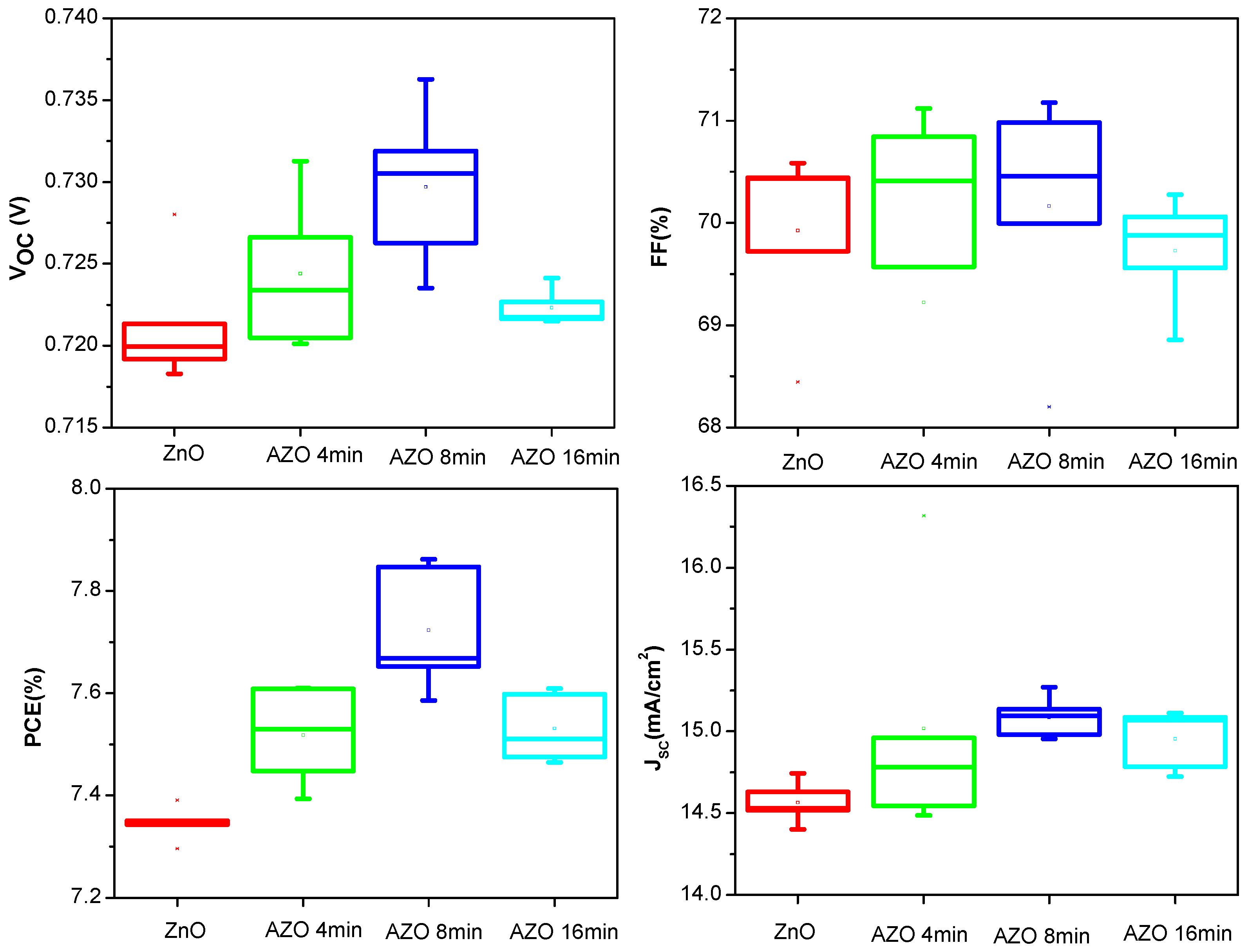
| Device | VOC (V) | JSC (mA/cm2) | FF (%) | PCE (%) |
|---|---|---|---|---|
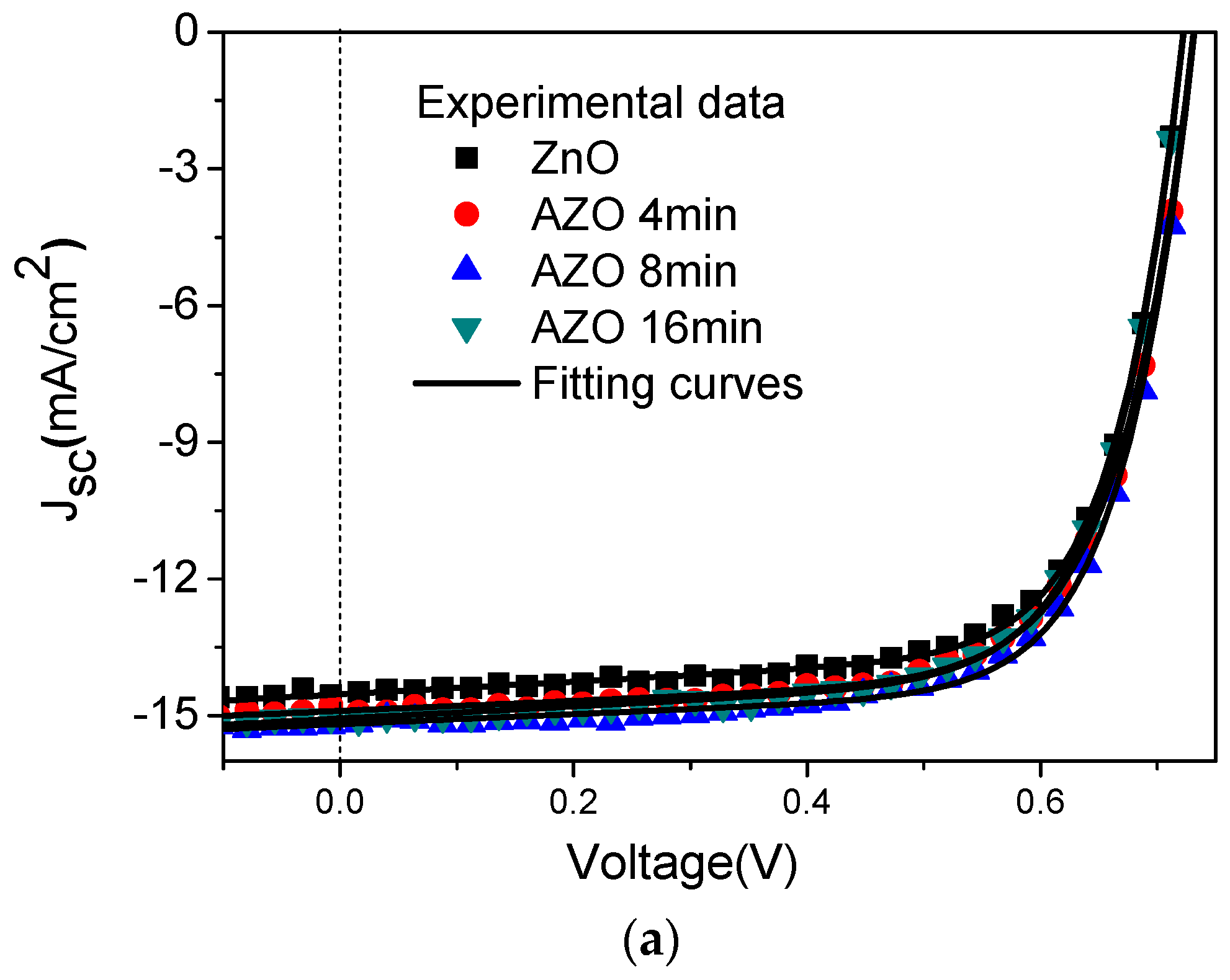
| ZnO | 0.721 | 14.52 | 70.58 | 7.39 |
| AZO 4 min | 0.731 | 14.96 | 69.57 | 7.61 |
| AZO 8 min | 0.732 | 15.13 | 70.98 | 7.86 |
| AZO 16 min | 0.723 | 15.06 | 69.88 | 7.60 |
© 2018 by the authors. Licensee MDPI, Basel, Switzerland. This article is an open access article distributed under the terms and conditions of the Creative Commons Attribution (CC BY) license (http://creativecommons.org/licenses/by/4.0/).
Share and Cite
Zhang, Q.; Peng, R.; Zhang, C.; Chen, D.; Lin, Z.; Chang, J.; Zhang, J.; Hao, Y. Inverted Organic Solar Cells with Low-Temperature Al-Doped-ZnO Electron Transport Layer Processed from Aqueous Solution. Polymers 2018, 10, 127. https://doi.org/10.3390/polym10020127
Zhang Q, Peng R, Zhang C, Chen D, Lin Z, Chang J, Zhang J, Hao Y. Inverted Organic Solar Cells with Low-Temperature Al-Doped-ZnO Electron Transport Layer Processed from Aqueous Solution. Polymers. 2018; 10(2):127. https://doi.org/10.3390/polym10020127
Chicago/Turabian StyleZhang, Qianni, Ruizhi Peng, Chunfu Zhang, Dazheng Chen, Zhenhua Lin, Jingjing Chang, Jincheng Zhang, and Yue Hao. 2018. "Inverted Organic Solar Cells with Low-Temperature Al-Doped-ZnO Electron Transport Layer Processed from Aqueous Solution" Polymers 10, no. 2: 127. https://doi.org/10.3390/polym10020127