A Pendulum-Like Motion of Nanofiber Gel Actuator Synchronized with External Periodic pH Oscillation

Abstract
: In this study, we succeeded in manufacturing a novel nanofiber hydrogel actuator that caused a bending and stretching motion synchronized with external pH oscillation, based on a bromate/sulfite/ferrocyanide reaction. The novel nanofiber gel actuator was composed of electrospun nanofibers synthesized by copolymerizing acrylic acid and hydrophobic butyl methacrylate as a solubility control site. By changing the electrospinning flow rate, the nanofiber gel actuator introduced an anisotropic internal structure into the gel. Therefore, the unsymmetrical motion of the nanofiber actuator was generated.1. Introduction
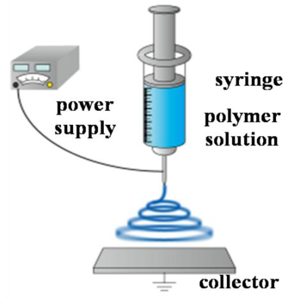
Polymer nanofibers have been researched for application in various fields, such as chemical detector, scaffolds, wound dressing, and multifunctional membranes [1-4]. Among various nanofiber production techniques [5,6], we investigated the electrospinning method. This is because electrospinning has a lot of merit such as low cost, relatively high production rate, and having applicability to many types of polymers. Figure 1 shows the schematic illustration of the electrospinning set-up. As a high voltage is applied to a metallic capillary of the syringe, charges that have built up on the surface of droplet on the top of the capillary, will overcome the surface tension and induce the formation of a liquid jet. The charged jet then undergoes stretching into continuous nanofibers and accelerates toward a grounded collector. On the way to the collector, the solvent evaporates. As a result, a non-woven mat composed of nanofibers is deposited on the collector.
The electrospinning method has succeeded in the fabrication of nanofibers by utilizing the many types of polymers [7-9]. Moreover, by controlling the external conditions, we can construct more complex structures such as porous fiber, core sheathe fiber, etc. [10-13]. Recently, some researchers have reported functional polymer hydrogels manufactured by utilizing electrospining. For example, Hsieh and coworkers have reported ultrafine hydrogel fibrous membranes that consist of poly(acrylic acid) (PAAc) [14], poly(N-isopropylacrylamide-co-acrylic acid) and poly(vinyl alcohol)(PVA) [15] and PVA/PAAc mixtures [16]. The hydrogel fibrous membranes have a high surface-to-volume ratio and a relatively small pore size compared to normal-type polymer hydrogel. Therefore, nanofiber hydrogels are expected to be applied to sensors, filtration media and biomaterials, etc. On the other hand, there are a few challenges in order to realize the nanofiber hydrogel actuator [17,18].
By utilizing the electrospinning method, we can construct the novel design of nanofiber gel actuators because it does not require a mold to synthesize the gel. In our previous study, by introducing an anisotropic structure into the nanofiber gel, we succeeded in the fabrication of a novel nanofiber hydrogel actuator that generates bending and stretching motions synchronized with the external manual pH changes [19]. However, the external pH was controlled manually. If the autonomous-type polymer gel actuator is realized, new transducers and molecular devices will be realized. In order to construct an autonomous polymer gel system, we utilized Landolt pH-oscillator based on a bromated/ sulfite/ferrocyanide reaction. By coupling with this pH-oscillator, we realized a nanofiber gel actuator that shows the bending and stretching motions over a constant period and displacement.
2. Experimental Section
2.1. Preperation of Poly(AAc-co-nBMA)
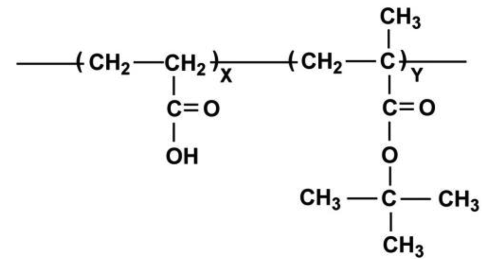
Using AAc (25.9 g) (KantoKagaku), butyl methacrylate (nBMA) (34.1 g) (Tokyo Kasei), and 2,2′-azobisiso-butyronitrile (AIBN) (0.49 g) (Tokyo Kasei) as an initiator, poly(AAc-co-nBMA) (Figure 2) was synthesized by the radical polymerization in ethanol (139.5 g) (Kanto Kagaku) using a total monomer concentration of 30 wt%. The molar ratio of nBMA incorporated into the copolymer was 30 mol%. The polymerization was carried out at 60 °C under nitrogen flow for 24 h in vacuo. The resulting reaction mixture was dialyzed against ethanol for seven days.
2.2. Electrospinning
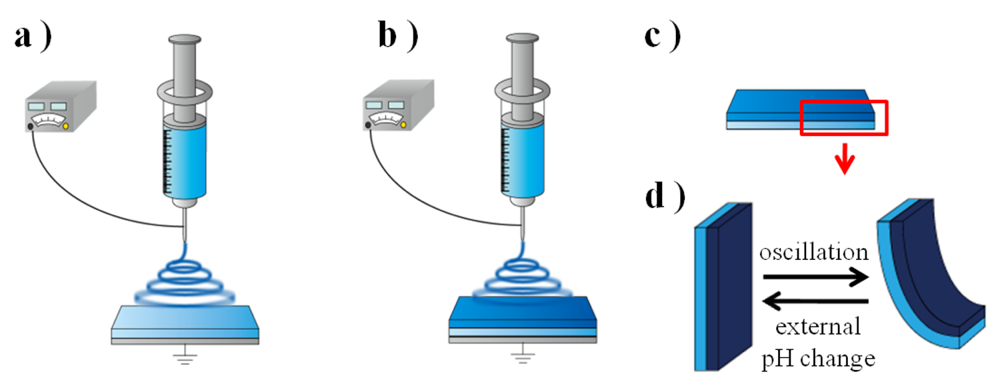
The polymer solution (18 wt%) was poured into a 2.5 mL syringe. A potential of 10 kV was applied by connecting the power supply (GT80 GREEN TECHNO) to the syringe tip. In order to introduce anisotropic structure into the nanofiber gel, the 1.0 mL of the polymer solution in the syringe was sprayed at a flow rate of 2.0 mL/hour (sprayed for 30 minutes), and then the flow rate was changed to 1.0 mL/hour (sprayed for 60 minutes). The electrospun fibers were collected on the grounded glass substrate as a collector. The distance between the collector and the syringe tip was 15 cm. The temperature and humidity were 25 °C and 70%, respectively. After the electrospinning, the obtained sheet, with a thickness of about 200 μm, was dried overnight at 50 °C.
2.3. Measurement of Motion of the Nanofiber Gel Actuator
The open continuously stirred tank reactor (CSTR) (40 mL) was designed using an acrylic cell with a water jacket. Potassium bromated (0.26 mol/L), sodium sulfite (0.3 mol/L), potassium ferrocyanide (0.08 mol/L), and sulfuric acid (0.04 mol/L), solutions were pumped into the reactor at a flow rate of 50 mL/hour. The pH changes in the reactor were monitored continuously by utilizing a pH meter (F-55 HORIBA) held in the reactor, and its electronic output was directly recorded by a computer. The nanofiber gel (length 15 mm, width 3 mm) was set at the bottom of the water jacket. One end of the gel strip was sandwiched in the incision of the silicone rubber. Shape changes of the gel strip were recorded by a fixed microscope (Fortissimo Corp. WAT-250D) and a video recorder (Victor Corp. SR-DVM700). The temperature in the reactor was controlled at 25 °C by utilizing the water bath equipment.
3. Results and Discussion
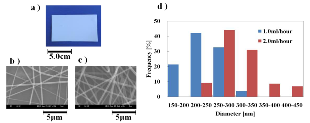
In this study, in order to drive the nanofiber gel actuator in response to the external pH changes, we selected the pH responsive poly(AAc) (PAAc) as a main polymer chain. The PAAc is protonated when the pH is below the pKa. When the pH of the solution is below pKa, the nanofiber gel collapses due to hydrogen bonding among the polymer chains. On the other hand, when the pH is above the pKa, the PAAc polymer chain is ionized, that is, the solubility of the polymer chain changes from a hydrophobic to a hydrophilic nature. As a result, the nanofiber gel expands because of the electrostatic repulsion force among the charged PAAc polymer chains. However, the fiber gel that consists of the only PAAc polymer chain, finally dissolves into the aqueous solution because the gel does not have the cross-linkage among the polymer chains into the nanofiber. In order to avoid the the nanofiber gel dissolving, especially when it is above the pKa, we adopted the nBMA domain into the PAAc as a cross-linkage and a solubility control site, due to the hydrophobic interaction among the nBMA in the nanofiber. As a result, the poly(AAc-co-nBMA) nanofiber gel does not dissolve in the aqueous solution. Figure 3 shows distributions of diameter of the poly(AAc-co-nBMA) nanofibers electrospun at two flow rates (2.0 mL/h and 1.0 mL/h) (See Figure 4). In general, the fiber diameters depend on the flow rate. In our experiment, the average diameter at the flow rate 2.0 mL/h (302 nm) was thicker than at 1.0 mL/h (233 nm).
In order to drive the nanofibrous gel actuator synchronized with autonomous pH oscillation, we focused on the Landolt pH-oscillator, based on a bromated/ sulfite/ ferrocyanide reaction discovered by Edblom et al. [20,21]. This reaction causes the autonomous cyclic pH changes with a wide range at room temperature. The reaction has many reaction steps, so we estimated the main reactions as follow [22].
In Process (1), H2SO3 is oxidized by bromate, and ferrocyanide is oxidized by bromate in Process (2). In the above two processes, the hydrogen ions produced and consumed at comparable rates. Therefore, in this reaction, the pH oscillation takes place in the CSTR. Figure 5 shows the experimental set up of the CSTR. The CSTR was constructed by using four peristaltic pumps in order to feed four solutions of potassium bromated, sodium sulfite, potassium ferrocyanide and sulfuric acid. Moreover, this system had one more peristaltic pump to drain the excess solution. The degree of changing the pH range (amplitude) and period of the oscillating reaction can be controlled by changing the feed concentration, flow rate and solution temperature.
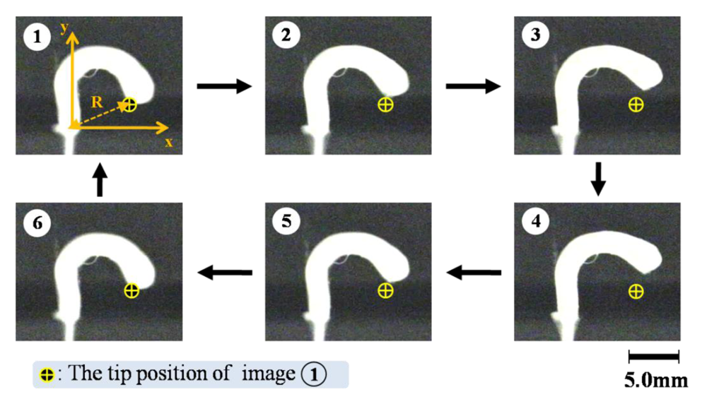
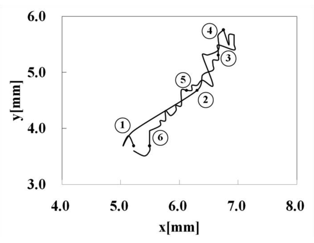
Figure 6 shows a motion of the nanofiber gel actuator. The bending and stretching motions of the gel actuator synchronized with the pH oscillating reaction. As shown in Figure 6, we defined R as the length between two edges of the gel. Figure 7 shows the trajectory of the nanofiber gel strip. As shown in Figure 7, the gel strip caused the pendulum-like motion. As the external pH is below the pKa, the nanofiber gel stretches because of the deswelling originating from the hydrogen bonding (1→3). Next, when the pH is above the pKa, the gel bends because of the swelling originating from the repulsive force among the anionic polymer chains (4→6).
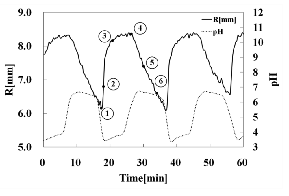
Figure 8 shows the temporal changes of R of the gel strip and the external pH, respectively. The range of the pH oscillation based on a bromate/sulfite/ferrocyanide reaction was 3.1 < pH < 7.2, and the period lasted about 20 min. When the external pH changes periodically, the R of the gel strip cyclic changes synchronized with the external pH change. As shown in Figure 8, when the pH sharply decreased, the R of the gel strip starts to increase because the gel collapsed. Next, when the pH increased rapidly, R gradually decreased, due to the gel actuator swelling originating from the repulsive force of AAc domain in the polymer chain. That is because the gel has different rates at swelling and deswelling. In general, the swelling motion of the gel is slower than the deswelling motion. Therefore, when the gel actuator bended, the R value gradually decreased.
4. Conclusions
In this study, we succeeded in the fabrication of nanofiber gel actuator with anisotropic internal structure by changing the flow rate in electrospinning. The developed gel generates bending and stretching motion according to the external pH. In order to drive the nanofiber gel actuator automatically, we focused on the pH oscillating reaction based on a bromate/sulfite/ferrocyanide reaction. As a result, we succeeded in causing the bending-stretching motion of the nanofiber gel actuator synchronized with the external pH oscillation. By analyzing the motion of the gel, we found that the gel actuator caused the pendulum-like motion. Moreover, we clarified that the displacement and period of the nanofiber gel were stable, which makes it promising as a molecular device for potential applications.


Acknowledgments
This work was supported in part by: (1) The Global COE (Centers of Excellence) Program, “Global Robot Academia”, Waseda University; (2) “Establishment of Consolidated Research Institute for Advanced Science and Medical Care,” Encouraging Development Strategic Research Centers Program, the Special Coordination Funds for Promoting Science and Technology, Ministry of Education, Culture, Sports, Science and Technology, Japan; (3) Grant-in-Aid for Young Scientists (B) (21750222); (4) Grant-in-Aid for Tokyo Ouka.
References
- Stevens, M.M.; George, J.H. Exploring and Engineering the Cell Surface Interface. Science 2005, 310, 1135–1138. [Google Scholar]
- Cui, Y.; Wei, Q.; Park, H.; Lieber, C.M. Nanowire Nanosensors for Highly Sensitive and Selective Detection of Biological and Chemical Species. Science 2001, 293, 1289–1292. [Google Scholar]
- Gu, S.Y.; Wang, Z.M.; Li, J.B.; Ren, J. Switchable Wettability of Thermo-Responsive Biocompatible Nanofibrous Films Created by Electrospinning. Macromol. Mater. Eng. 2010, 295, 32–36. [Google Scholar]
- Li, D.; Xia, Y. A Fine Set of Threads. Nature 2001, 411, 236. [Google Scholar]
- Xia, Y.; Yang, P.; Sun, Y.; Wu, Y.; Mayers, B.; Gates, B.; Yin, Y.; Kim, F.; Yan, H. One-Dimensional Nanostructures: Sythesis, Characterization, and Applications. Adv. Mater. 2003, 15, 353–389. [Google Scholar]
- Martin, C.R. Membrane-Based Synthesis of Nanomaterial. Chem. Mater. 1996, 8, 1739–1746. [Google Scholar]
- Darrell, H.R.; Alexander, L.Y. Electrospinning Jets and Polymer Nanofibers. Polymer 2008, 49, 2387–2425. [Google Scholar]
- Gu, S.Y.; Wang, Z.M.; Li, J.B.; Ren, J. Conductive Polypyrrole Nanofibers via Electrospinning: Electrical and Morphological Properties. Polymer 2006, 47, 1597–1603. [Google Scholar]
- Tamer, U.; Flemming, B. Electrospinning of Uniform Polystyrene Fibers: The Effect of Solvent Conductivity. Polymer 2008, 49, 5336–5343. [Google Scholar]
- Yu, J.H.; Sergey, V.F.; Gregory, C.R. Production of Submicrometer Diameter Fibers by Two-Fluid Electrospinning. Adv. Mater. 2004, 16, 1562–1566. [Google Scholar]
- Dan, L.; Gong, O.; Jesse, T.M.; Younan, X. Collecting Electrospun Nanofibers with Patterned Electrodes. Nano Lett. 2005, 5, 913–916. [Google Scholar]
- Donzhi, Y.; Jianfeng, Z.; Jing, Z.; Jun, N. Aligned Electrospun Nanofibers Induced by Magnetic Field. J. Appl. Polym. Sci. 2008, 110, 3368–3372. [Google Scholar]
- Bogntizki, M.; Frese, T.; Steinhart, M.; Greiner, A.; Wendoreff, J.H. Preparation of Fibers with Nanoscaled Morphologies: Electrospinning of Polymer Blends. Polym. Eng. Sci. 2001, 41, 982–989. [Google Scholar]
- Li, L.; Hsieh, Y. Ultra-fine Polyelectrolyte Fibers from Electrospinning of Poly(acrylic acid). Polymer 2005, 46, 5133–5139. [Google Scholar]
- Chen, H.; Hsieh, Y. Ultrafine Hydrogel Fibers with Dual Temperatureand pH-Responsive Swelling Behaviors. J. Polym. Sci. A Polym. Chem. 2004, 42, 6331–6339. [Google Scholar]
- Jin, X.; Hsieh, Y. pH-Responsive swelling behavior of poly(vinyl alcohol)/poly(acrylic acid) bi-component fibrous hydrogel membranes. Polymer 2005, 46, 5149–5160. [Google Scholar]
- Okuzaki, H.; Kobayashi, K.; Yan, H. Thermo-Responsive Nanofiber Mats. Macromolecules 2009, 42, 5916–5918. [Google Scholar]
- Jin, X.; Hsieh, Y. Electrospinning pH-Responsive Block Copolymer Nanofibers. Adv. Mater. 2007, 19, 3544–3548. [Google Scholar]
- Nakagawa, H.; Hara, Y.; Maeda, S.; Hashimoto, S. A Novel Design of Nanofibrous Gel Actuator by Electrospinning. IEEE Nano 2010. [Google Scholar] [CrossRef]
- Edblom, E.C.; Orban, M.; Epstein, I.R. A New Iodate Oscillator: The Landolt Reaction with Ferrocyanide in a CSTR. J. Am. Chem. Soc. 1986, 108, 2826–2830. [Google Scholar]
- Edblom, E.C.; Luo, Y.; Orban, M.; Kustin, K.; Epstein, I.R. Kinetics and Mechanism of the Oscillatory Bromate-Sulfite-Ferrocyanide Reaction. J. Phys. Chem. 1989, 93, 2722–2727. [Google Scholar]
- Crook, J.; Smith, A.; Jones, A.; Ryan, J. Chemically Induced Oscillations in a pH-Responsive Hydrogel. Phys. Chem. Chem. Phys. 2002, 4, 1367–1369. [Google Scholar]
© 2011 by the authors; licensee MDPI, Basel, Switzerland. This article is an open access article distributed under the terms and conditions of the Creative Commons Attribution license (http://creativecommons.org/licenses/by/3.0/).
Share and Cite
Nakagawa, H.; Hara, Y.; Maeda, S.; Hasimoto, S. A Pendulum-Like Motion of Nanofiber Gel Actuator Synchronized with External Periodic pH Oscillation. Polymers 2011, 3, 405-412. https://doi.org/10.3390/polym3010405
Nakagawa H, Hara Y, Maeda S, Hasimoto S. A Pendulum-Like Motion of Nanofiber Gel Actuator Synchronized with External Periodic pH Oscillation. Polymers. 2011; 3(1):405-412. https://doi.org/10.3390/polym3010405
Chicago/Turabian StyleNakagawa, Hiroki, Yusuke Hara, Shingo Maeda, and Shuji Hasimoto. 2011. "A Pendulum-Like Motion of Nanofiber Gel Actuator Synchronized with External Periodic pH Oscillation" Polymers 3, no. 1: 405-412. https://doi.org/10.3390/polym3010405