Exploit the Bandwidth Capacities of the Perfluorinated Graded Index Polymer Optical Fiber for Multi-Services Distribution

Abstract
: The study reported here deals with the exploitation of perfluorinated graded index polymer optical fiber bandwidth to add further services in a home/office network. The fiber properties are exhibited in order to check if perfluorinated graded index plastic optical fiber (PFGI-POF) is suitable to support a multiplexing transmission. According to the high bandwidth length of plastic fibers, both at 850 nm and 1,300 nm, the extension of the classical baseband existing network is proposed to achieve a dual concept, allowing the indoor coverage of wireless signals transmitted using the Radio over Fiber technology. The simultaneous transmission of a 10 GbE signal and a wireless signal is done respectively at 850 nm and 1,300 nm on a single plastic fiber using wavelength division multiplexing commercially available devices. The penalties have been evaluated both in digital (Bit Error Rate measurement) and radiofrequency (Error Vector Magnitude measurement) domains.1. Introduction
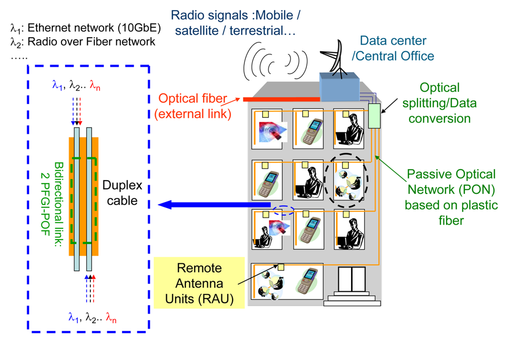
Nowadays, the plastic fiber technology remains one of the challenging solutions for small office/home office network deployments as compared to the glass fiber technology. In fact, polymer fibers are less brittle and more flexible than glass and should reasonably restrict their use to home/office applications where their easy handling should aid the “Do It Yourself concept” (DIY). Of the commercially available plastic fibers, PolyMethylMethAcrylate (PMMA) and perfluorinated graded index polymer optical fibers (POF) represent the two mains candidates able to be used for high speed/medium range home/office network, due to their bandwidth, as compared to the step index, capabilities. While the graded index POF based on PMMA material are restricted to telecommunication systems in the visible range due to the high fiber attenuation of the PMMA within the infrared (IR) spectra, perfluorinated graded index plastic optical fiber (PFGI-POF) seems to be a prime candidate to be used with high speed (>1 Gbps) and commercial off the shelf infrared transceivers. The PFGI-POF exhibits high bandwidth capacities within the IR spectra and in particular both at 850 nm and 1,300 nm. The concept of multi-services distribution developed here for the PFGI-POF originates from the combined use of high bandwidth fiber and Coarse Wavelength Division Multiplexing (CWDM) technique in order to fully exploit the PFGI-POF bandwidth capacities. The study reported here has the advantage to multiplex several services on the same PFGI-POF. According to the high bandwidth length products of the plastic fibers both at 850 nm and 1,300 nm, the idea is to extend the classical baseband existing network to a dual concept providing the indoor coverage of wireless signals transmitted using the Radio over Fiber technology. This concept is very useful when the two transmitted signals exhibit potential overlapped spectrum. The simultaneous transmission of a 10 GbE signal and a wireless signal is done respectively at 850 nm and 1,300 nm on a single plastic fiber with wavelength division multiplexing commercially available devices. Some experiments aiming to demonstrate the simultaneous transmission of different signals have been reported using either electrical or optical multiplexing schemes. For example, electrical multiplexing has been used by Kamisaka et al. [1] to demonstrate the dual transmission of a baseband signal at 9.95328 Gbps and a 60 GHz wireless radio signal handling a 155 Mbps data signal. The optical transmission was carried out on a dispersion shifted single-mode glass fiber at a single wavelength (1,550 nm) using external modulation scheme and both electrical and optical filters which increase the link cost. More recently, Gasulla et al. [2] have reported the simultaneous baseband (2.5 Gbps NRZ data stream) and radio signals (sub-carrier multiplexed cable television CATV) transmission over glass multimode fiber (length: 5 km). The dual transmission is performed using wavelength multiplexing around 1,550 nm. Highly stabilized laser sources, as well as external modulation, were used which also lead to an expensive infrastructure for home or office networks compared to a solution using the direct modulation of uncooled laser. Lethien et al. have already reported the concept of multi-services distribution over the OM4 glass multimode fiber [3,4]. The improvement of the indoor coverage of wireless communications signals in shadowed area (radiocellular (Global System for Mobile communications (GSM), Digital Cellular System (DCS), Enhanced Data rates for GSM Evolution (EDGE), Universal Mobile Telecommunication System (UMTS)), WLAN (IEEE802.11a, b, g, etc.) and WPAN (Bluetooth, Zigbee, UWB, standards, etc.) using carrier frequencies up to buildings, tunnels or shopping centers is realized with the Radio over Fiber (RoF) technology. The RoF concept allows transportation by optical means, a radio signal from a central office to multiple remote access points through a fiber network, in order to extend the wireless range and to provide a wireless coverage in shadowed area. Using Ultra Coarse Wavelength Multiplexing (i.e., 850 nm and 1,300 nm) which is affordable using WDM multimode couplers, the radio over fiber technology can be used with the digital baseband transmission on the same multimode PFGI-POF fiber converting, so this supports a multi-services transmission media (Figure 1).
To the authors' knowledge, the combined transmission of high data rate (10 Gbps) digital baseband signal with radiofrequency signal, using low cost wavelength division multiplexing (WDM) devices and PFGI-POF fibers, is reported for the first time. To this end, PFGI-POF should be fully characterized as a multiple transmission media both at 850 nm and 1,300 nm. The methodology used to demonstrate the multi-services concept is described in this review manuscript. The first part will report the PFGI-POF properties of the commercially available fibers able to support the multi-services distribution (description of the core and cladding material, numerical aperture, mode field diameter, attenuation and bandwidth). Then, results obtained for the 10 GbE transmission over the PFGI-POF at 850 nm are reported in the second part, in which the advantages and drawbacks of each PFGI-POF will be highlighted. In a third part, Radio over Fiber system based on PFGI-POF will be presented. Finally, the multi-services distribution deployed on PFGI-POF is demonstrated for home/office network with a great robustness against the transmission of several radiofrequency standards which clearly demonstrated the bandwidth capacities of such optical fibers.
2. Results and Discussion
The first part clearly describes the PFGI-POF physical properties aiming to demonstrate the potential of such fibers for high speed and dual transmission scheme.
2.1. Physical Properties and Fabrication Process of PFGI-POF
2.1.1. Material Properties and Fabrication Process
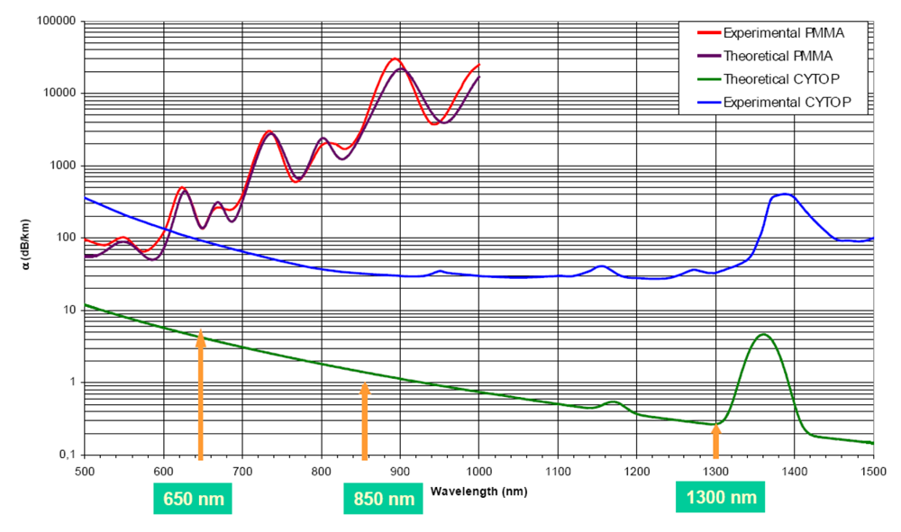
Thermoplastic PMMA (Polymethylmethacrylate) has been the first material used for POF fabrication. Known under the acronym Plexiglass®, the PMMA is an organic compound based on a polymerized material with an amorphous structure and a glass transition temperature (Tg) close to 100 °C. The Plexiglass® is composed of several MMA monomers, each of them showing 8 C–H bonds as described in Figure 2(a). The 6th and 5th harmonic waves (occurring at 627 nm and 736 nm respectively) of the MMA monomer are responsible for the high level of attenuation of the PMMA based POF, especially from the visible to the infra-red spectral ranges (110 dB/km at 650 nm). In order to decrease the intrinsic absorption of the PMMA based POF resulting particularly from the vibrational overtones, the idea is to perform the partial or complete substitution of the hydrogen compound by heavy atoms like deuterium (also called heavy hydrogen 2H, a stable isotope of hydrogen having twice the atomic mass of the hydrogen atom) or fluorine atoms. Even if the use of heavy hydrogen induces a significant improvement of the fiber attenuation [5] over the visible spectrum (one order of magnitude), the deuterium based POF are very sensitive to the water vapor in the ambient air which is absorbed by the core material leading to an increase of the attenuation (In fact, the deuterium is progressively replaced by hydrogen atoms resulting from the water vapor contamination inside the fiber).
By replacing the hydrogen atoms with fluorine atoms inside the fiber core, it is possible to reject the absorption bands (C–F bonds) of the used material to the infra-red spectra, far away from the telecommunication window (850 nm–1,550 nm). According to the available [6] polymer materials (polytetrafluoroethylene (PTFE), tetrafluoroethylene-perfluoroalkyl vinyl ether (PFA), etc.)), the minimum fiber absorption has been obtained by Asahi Glass Company (AGC) from Japan with the cyclic transparent optical polymer (CYTOP®), which contains only C–F bonds as shown in Figure 2(b). The CYTOP® material is an amorphous fluoropolymer having a Tg close to 108 °C and where the graded index variation inside the fiber core is realized by copolymerization of two monomers and by a doping process (interfacial-gel polymerization method).
Nevertheless, even if the fiber attenuation decreases to 15 dB/km at 1,300 nm (Figure 3) with the use of the CYTOP® material, the calculated attenuation [6] threshold is not reached mainly due to the extrinsic losses induced by the fabrication process (impurities owing to the gas, material crystallization (scattering centers, contamination and so on). Several manufacturing processes have been reported to make the fabrication of the graded index POF:
the interfacial gel polymerization technique;
the centrifuging process and the combined copolymerization/rotating methods;
the combined extrusion of the core and the cladding materials.
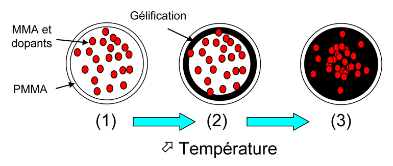
Koike et al. [8-10] from the Keio University (Japan) have developed the interfacial gel polymerization method to realize the preform (Figure 4). A mixture composed of two kinds of monomers (a classical one and a dopant) has been inserted in a tube (diameter equivalent to the preform diameter) and heated at 80 °C to be preliminary liquefied.
During this process, the formation of a gel layer is done in the inner wall of the tube (polymer gel phase) and the smaller size monomer diffuses from the edge of the preform to the center in order to form the graded index profile. The graded index profile is correlated to the dopant distribution inside the preform. This fabrication process is applied to fabricate the fiber preform at Asahi Glass Company (AGC): the obtained fiber is known under the Lucina acronym.
Owing to the density difference between the two monomers, the centrifuging method [11] could be used to produce POF preforms. More specifically, a gravitational field is used in the process to generate and to fix compositional gradients in homogeneous mixtures of monomers, mixtures of polymers and polymer-monomer mixtures according to the molecular weight. In this manufacturing method, the rotation speed is kept below 25,000 rotations per min (rpm).
The PFGI-POF is then obtained by using both the fabricated preform and classical means able to draw the fiber.
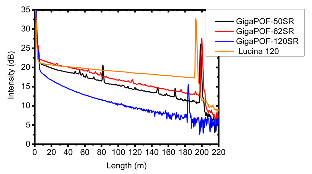
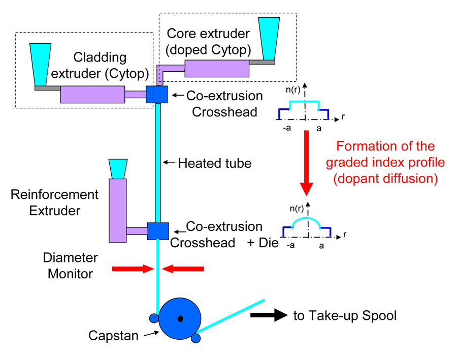
The Chromis fiberoptics company lead by W. White has performed the fabrication of POF based on the CYTOP® material with the use of the co-extrusion process (no preform fabrication has to be done). Two extruders, containing respectively the CYTOP® material for the cladding and the CYTOP® fluoropolymer including dopant for the fiber core, are used to fill a heated tube (Figure 5). Owing to the thermal polymerization, the dopant diffuses from the center to the outer edge in order to form the graded index profile [12]. The fiber attenuation shape depends strongly on the manufacturing process as some impurities could be added inside the core material leading to extrinsic losses. The optical backscattering reported in Figure 6 clearly shows that the co-extrusion process leads to high fiber attenuation contrary to the classical process (preform and fiber draw tower). Defects are materialized by the smaller backscattering peaks that appear all along the propagation. The PFGI-POF issued by Chromis Fiberoptics (in particular the 50 μm sample) exhibit some intensity peaks unlike the ones from the Asahi Glass (Lucina).
The fiber length inside a building is generally limited between 50 m and 300 m [13] and the PFGI-POF seems to have suitable properties to achieve the link budget requirement (bandwidth and attenuation) for high data rate baseband transmission and RoF systems. In fact, the relative low attenuation (∼30 dB/km) in the expected spectral range (850 nm–1,300 nm), contrary to the PMMA based PFGI-POF (more than 100 dB/km in the visible range), as well as their bandwidth, allows using them to design high speed and low losses small office/home office networks. Currently, two manufacturers have been identified as supplying perfluorinated graded index polymer optical fibers. As mentioned previously, Asahi Glass Company commercialized the Lucina fiber in early 2000 (technological transfer of the interfacial gel polymerization method from Koike, et al.). The high purity of the fluoropolymer developed by Asahi Glass Company leads to very promising products with small losses and high bandwidth performance (Table 1).
This fiber has a 120 μm core diameter and a numerical aperture close to 0.185. Since April 2009, AGC Company has proposed Lucina-X PFGI-POF that includes a double cladding in order to decrease the sensitivity of such fibers to bending effects. Since 2005, Chromis Fiberoptics used the co-extrusion process to fabricate the PFGI-POF. This process is well adapted to mass production as no preform is needed. The core diameter of the Chromis Fiber Optics PFGI-POF varies from 50 μm up to 120 μm (Table 1). Actually, only the 120 μm core diameter based PFGI-POF Lucina and GigaPOF-120SR have been standardized under the A4G category. A PFGI-POF based on a 62.5 μm core diameter is standardized under the A4h acronym but this fiber exhibits a 245 μm cladding diameter value contrary to the GigaPOF-62SR (500 μm). An update of the IEC-60793-2-40 document [14] is needed to standardize the 50 μm and 62.5 μm based PFGI-POF issued from Chromis Fiberoptics.
2.1.2. Measurement of the Numerical Aperture (NA)
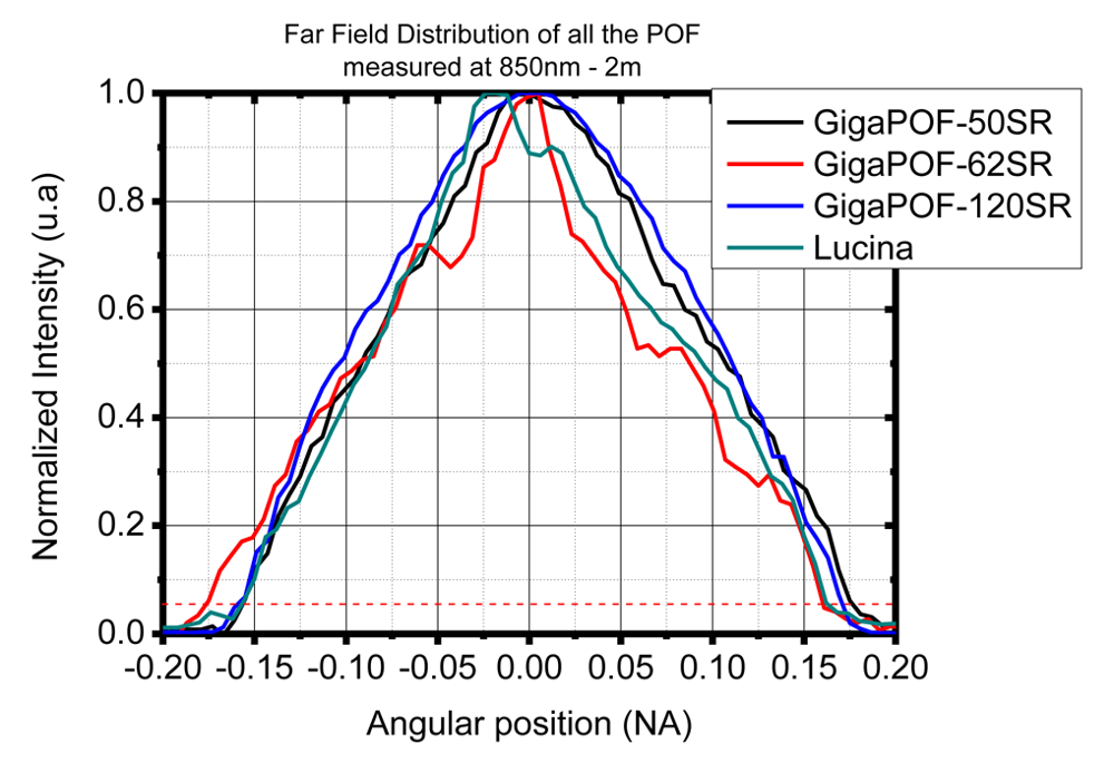
The evolution of the PFGI-POF numerical aperture (far field measurement according to the standardized procedures [15,16]) is reported in Figure 7. A mean value (measured at 5% of the maximum intensity) close to #0.18 has been exhibited for the four, PFGI-POF which is near the datasheets values. This value is lower than the NA values of the glass multimode fibers (NAglass ∼ 0.2). This measurement is effectively important particularly for producing the best optical coupling efficiency between the used laser and the PFGI-POF. In our case, most of this study complies with the use of a vertical cavity surface emitting laser, having a NA close to 0.3. It can be noted that the NA value of a PMMA based POF is close to 0.5.
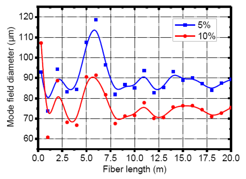
2.1.3. Mode Field Diameter
The evolution of the mode field diameter inside the PFGI-POF core has been evaluated as an important parameter. In fact, mismatches between photodetector active area and fiber core diameter may cause excess optical losses [17,18]. The evolution of the mode field diameter as a function of the fiber length is then performed applying the near field optical power distribution technique. The mode power re-distribution inside the fiber core inherent to the impurities quantity in the core material induces a huge variation of the mode field diameter and therefore random coupling losses at the photodetector side. Figure 8 shows the measurements done with the GigaPOF120-SR (length: 20 m). The mean value of the mode field diameter of the GigaPOF-120SR is close to 85 μm (5% measurement) from 7 m to 20 m, indicating that a strong mode coupling occurs inside the fiber core to re-distribute the optical power: the GigaPOF-120SR is already in a steady state configuration after a propagation length equal to 7 m (Figure 8). No random coupling losses at the photodetector side are observed for the four PFGI-POF.
2.1.4. Evaluation of the Fiber Bandwidth
Contrary to the single mode fiber (SMF), the frequency response of the multimode fiber strongly depends on the spatial distribution of the power within the fiber and therefore on the modal launching conditions. This spatial distribution is correlated to the number of propagation mode inside the fiber core: the intermodal dispersion is the main limitation of the fiber bandwidth. Depending on the index profile and the wavelength, mode groups propagate at different velocities and the difference in propagation time between the fastest and the slowest modes groups is known as the Differential Mode Delays. Even if the PFGI-POF have been optimized to reduce these delays (graded index profile), the DMD should be minimized in order to provide a high bandwidth/length product suitable for high speed communication.
Figure 9 shows the DMD charts of the four PFGI-POF and Table 2 summarizes the calculated DMD values. The DMD measurements [17] have been done with a test setup allowing the variation of the launch conditions (transversal sweep with a small size spot in front of the fiber core).
The measured DMD are well correlated to the fiber bandwidth measurement (Figure 10) and demonstrate the relative insensitivity of the large core PFGI-POF modal bandwidth to an offset launch injection.
The “Do it Yourself” concept is fully justified as a large offset launch does not influence the modal bandwidth of the PFGI-POF. From a material point of view, the CYTOP® perfluorinated material exhibits a promising dispersion leading to high bandwidth capacities as depicted in Figure 11.
To confirm the high potential of the PFGI-POF to a misalignment, optical losses measurements (Figure 12), as a function of a transversal offset launch, are then carried out between two PFGI-POF (10 m length) having the same core diameter in order to effectively demonstrate the huge tolerance of such plastic fiber to an offset coupling. 3 dB optical losses is obtained for lateral offset coupling close to 56 μm (r/a ∼ 0.9) indicating that such a fiber is appropriate for a low cost system requiring a low level of maintenance.
We have shown that the four presented PFGI-POF exhibit some interesting properties: acceptable fiber attenuation, high fiber bandwidth, core diameter and NA suitable to be compatible with commercially available devices such as 850 nm VCSEL and large active area (#70 μm) photodetectors. Moreover, the PFGI-POF remains a very challenging solution for home office/small office networks due to their ease of connection. No expensive tools are required to provide a clean facet of the fiber, contrary to the glass fiber world. Clip-on connectors have been developed by Nexans and Chromis Fiberoptics to be fixed on the external coating of the PFGI-POF which favor the Do it Yourself concept. Nevertheless, the bandwidth potentialities of the PFGI-POF do not actually achieve the glass fiber bandwidth capabilities. The polymer fiber attenuation needs also to be improved in order to increase the link budget and to be competitive against the glass fiber.
2.2. Baseband Data Transmission over PFGI-POF at 10 Gbps
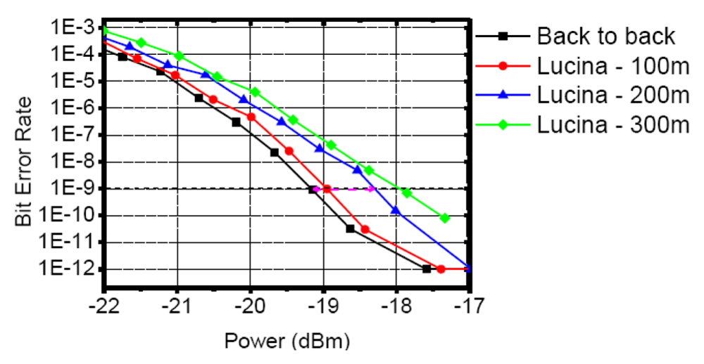
A preliminary study dealing with lower data rate (1.25 Gbps) has been performed according to the Gigabit Ethernet standard (GbE). The transmission has been demonstrated through the large core diameter Lucina fiber at 850 nm (length: 100 m up to 300 m). The Bit Error Rate (BER) has been measured as a function of the received optical power to exhibit the power dispersion penalties of the PFGI-POF at 1.25 Gbps (Figure 13). The power dispersion penalties are close to 1.2 dB for 300 m length.
In order to vary the optical power inside the PFGI-POF link, a tailormade optical attenuator (Figure 14) has been designed: it is composed of two PFGI-POF patchcords, two graded index (GRIN) lenses and a disk with adjustable optical density. The insertion loss of the designed attenuator is close to −1.5 dB at 850 nm.
The eye diagram of the fiber link is depicted in Figure 15 and clearly shows the bandwidth capacities of the PFGI-POF. In order to study the evolution of the BER inside the eye diagram, a isoBER plot measurement has been carried out and is reported in Figure 15. The preliminary study has been done in order to understand the behavior of the PFGI-POF, to design a POF based optical attenuator and to exhibit the performances of such a fiber. The 10GbE transmission over a PFGI-POF has been proposed firstly by Giaretta et al. [20]. A fiber transmission at 11 Gbps occurring at 1,300 nm over 100 m has been reported. This preliminary reported work at a higher data rate has been performed with a 1,300 nm Fabry Perot laser and coupling optics which are not suited for a low cost 10 Gbps optical network.
In [18], it has been proposed to investigate the use of conventional low cost devices such as VCSEL (Vertical Cavity Surface Emitting Laser) and PIN (Positive-Intrinsic-Negative) photodiodes with plastic fiber in order to have a pragmatic approach to the future high speed optical network. The Phyworks technology [21], which consists of using Electronic Dispersion Compensation devices (EDC) placed at the electrical output of a conventional photoreceiver (here, a GaAs photodiode), has been used. The EDC technology overcomes the modal dispersion of the multimode fibers either in glass or polymer. Phyworks Company wants to produce 10 Gbps TX/RX module including VCSEL TOSA (Transceiver Optical SubAssembly) and driver for the TX part and photodiode ROSA (Receiver Optical SubAssembly), EDC and transimpedance amplifier (TIA) chips for the RX part with a target price of less than USD 200 per module. The coupling pair EDC/TIA cost should be around USD 55 (less expensive devices to the ones used in [20]). EDC technology is a cost effective solution to combat the intermodal dispersion inherent to the optical link based on the multimode fiber. The Phyworks serial EDC replaces the existing Clock Data Recovery (CDR) of a classical 10 Gigabit Small Form Factor Pluggable Module (XFP).
The transmission of a 10.3125 Gbps baseband signal over the four PFGI-POF (GigaPOF50-SR, GigaPOF62-SR, GigaPOF120-SR and Lucina) has been performed (Figure 16). As mentioned previously, the study done by Giaretta et al. [20] has been achieved at 1,300 nm and with a 130 μm core diameter PFGI-POF. The restricted mode launch conditions of the PFGI-POF have been simulated with a single mode fiber coupled to the 1,300 nm laser in order to decrease intermodal dispersion effects. Moreover, in order not to induce mode filtering at the receiver, and to reduce the coupling losses due to the mismatch between the large core PFGI-POF and the photodetector, collimating and focusing lenses inducing 4.8 dB coupling losses have been proposed by Giaretta et al. The study reported by Lethien et al. [18] is performed at 850 nm (wavelength compatible with low cost 10 G XFP transceiver) and without adaptive optics between the tested PFGI-POF and the photodetector. In order to exhibit the power dispersion penalties, the Bit Error Rate (BER) as a function of the received optical power have been measured in: (1) the back-to-back case; and (2) by inserting the required length corresponding to the four fibers being tested (Figure 16). The fiber length is close to 100 m.
The BER values from the measurements performed on the GigaPOF50-SR PFGI-POF did not provide any good results and a concentricity mismatching between the fiber core and the cladding is suspected. The exhibited power dispersion penalties are summarized for a BER = 10−9 in Table 3.
The main conclusions are summarized in [18]. The GigaPOF62-SR, the GigaPOF120-SR and the Lucina fibers coupled to an EDC device, exhibit power dispersion penalties around 4 dB. These penalties are inherent to the modal bandwidth of the fiber. From the results summarized in Table 3, the potential impact of the EDC technology for the 10 GbE over PFGI-POF is clearly demonstrated. Effectively, the 10 GbE transmission over the GigaPOF62-SR (length: 100 m) has been achieved with a BER value close to 10−12. The mask testing measurements reported in Figure 17 corroborate the technological improvement obtained using EDC devices. In fact, using the conventional photoreceiver (RX part of the low cost Picolight XFP) leads to a BER close to 10−7. The BER stays around 3 × 10⁻¹² when the EDC device is activated. The eye opening is then higher with the use of the EDC device. It has been shown that the EDC device enhances the signal quality by reducing the intersymbol interference phenomena which demonstrates without doubt, the potential of this technology.
An increase of the transmission length as well as the data rate are reported which clearly demonstrated the enhancement of the PFGI-POF performances. The 40 Gbps transmission over 30 m of the GigaPof-50SR both at 1,550 nm and 850 nm has already been reported by [22]. An increase of the link length is then realized by the same group and similar transmission over the GigaPOF62-SR PFGI-POF has been demonstrated by Polley et al. [23]. The link is limited to 100 m and the Fabry Perot laser operates at 1,315 nm.
In 2007, an interesting comparative study between glass and PFGI-POF has been performed regarding the sensitivity of such fibers to the offset launch, for data rate close to 40 Gbps and link length of less than 100 m [24]. The feasibility of error free transmission at 1,550 nm with either 100 m of glass multimode OM3 Fiber or 50 m of GigaPOF50-SR is therefore performed for a signal having a bit rate close to 40 Gbps. To obtain such results, offset launches close to ±3 μm for the glass multimode fiber and ±10 μm for the PFGI-POF have been employed.
2.3. Radio over Fiber System with PFGI-POF
The previous section of the paper has clearly demonstrated that the PFGI-POF is a suitable candidate for high speed baseband signal transmission up to 10 Gbps with fiber length close to 100 m. This length value is compatible with an in-building network. Before describing the RoF technology, the CATV over POF is introduced as the transmitted signal is of the same nature as those used in RoF transmission. The feasibility of transmitting analogue CATV signals over a combination of singlemode and POF links has been demonstrated [25]. Recently, some new POFs have been developed with better performances and at a lower cost. These products greatly enhance the POF LAN research and have been utilized to transmit digital baseband and radiofrequency modulated signals for in-door application. Nevertheless, none of the above architectures have been considered to transmit optical CATV signals all the way from the central office (CO) to the home and then to the consumer in-house devices.
The RoF technology allows the transmission of the radiofrequency narrow band or ultra wide band signal (RF) from a central office to several picocell access points able to provide RF coverage in shadowed areas. Of the POF available on the market, only the perfluorinated CYTOP® based plastic fiber is used for the distribution of radio signals over optical multimode fiber (RoF), mainly owing to its relative low attenuation in the infrared domain (contrary to the PMMA based POF). In [26], the improvement of the indoor coverage of radiocellular signals such as GSM and UMTS has been realized with the Lucina fiber using a RoF topology based on the Intensity Modulation-Direct Detection (IMDD) technique. The Error Vector Magnitude (EVM)—which is the best figure of merit to analyze a radiofrequency signal—has been evaluated after the transmission over glass [27] and POF multimode fibers in order to exhibit the different behavior according to the radio signals propagation inside the fiber core (Figure 18).
The results show that the Lucina fiber constitutes without any doubt a promising candidate in RoF system using commercially available components manufactured for glass fibers. Moreover, because of its higher core diameter, POF does not induce modal noise penalties as in glass multimode fiber links [28] and the alignment is also less critical, thus reducing the cost of the optical active and passive devices including the installation and maintenance costs of the connections. Its higher flexibility based on “plastic” material offers a great advantage compared to the silica fiber which is more brittle. Nevertheless, the higher core diameter of the fiber with respect to the active area of some high speed detectors causes an additional power penalty.
Lethien et al. [29,30] has demonstrated the potential of glass and plastic multimode fibers to transmit the Wimedia multiband orthogonal frequency division multiplexing ultra wide band (MB OFDM UWB) standard over more than 1 km and 200 m respectively for the glass and the plastic fibers. The data rate of the wireless tested ultra wide band signal is between 200 Mbps and 480 Mbps. The influence of the fibers properties (attenuation, bandwidth/length product, etc.) on the link quality (Figure 19) has been exhibited and two different behaviors of the core material have been observed.
2.4. Multi-Services Application over Polymer Fiber
It has been clearly demonstrated that the PFGI-POF could be a challenging solution—not only for the high data rate baseband transmission (reasonably up to 10 Gbps) but also for the deployment of a RoF system—each of these subsystems being tested with fiber length from 50 m to 100 m. The high bandwidth capacities of the PFGI-POF both at 850 nm and 1,300 nm could be exploited to transmit simultaneously the two desired signals over the same fiber. The coarse wavelength division multiplexing (WDM) devices available in the glass fiber world are used to achieve dual transmission and to address the multi-services concept with PFGI-POF (Figure 1). According to the focused application dealing with the deployment of a home or office fiber network, the fiber length could be restricted to 100 m which would allow transmission simultaneously over a single PFGI-POF a 10 GbE signal at 850 nm and a radio signal at 1,300 nm, using the WDM devices.
The evaluation of the penalties owing to the mismatching between the WDM devices and the PFGI-POF wass proposed and realized by using the test setup depicted in Figure 20.
From the devices used, the lowest cost infrastructure currently achievable with components off the shelf is obtained. This photonic system appears to be a costless evolution from a typical 10 GbE network that offers the transmission of different services that potentially have overlapping spectra: only the low cost wavelength multiplexing devices are then needed to add a further service (radio signal) to a typical 10 GbE fiber network. The penalties and the performance of the developed system are then exhibited for the digital (850 nm path) and the radio over fiber (1,300 nm path) signals. The WDM devices used in these experiments have already been characterized and reported in [4]. The Bit Error Rate (BER) as a function of the received optical power is studied first (Figure 21).
It is clear that the GigaPOF62-SR (length: 100 m) could minimize the BER in such a system compared to the Lucina-X PFGI-POF.
A BER value close to 10−11 is then achieved with the fiber produced by Chromis Fiberoptics. The best BER value obtained with the Lucina-X fiber (length: 100 m) is 10−4. The core diameter and numerical aperture mismatching, between the Lucina-X plastics fiber (120 μm) and the WDM devices based on 50 μm core diameter glass multimode fiber, induce a mode filtering at the photoreceiver part resulting in additional penalties. A decrease of the fiber length close to 50 m obtains a 5 × 10⁻⁸ BER (Figure 21 left). Figure 21 (right) reports the BER evolution of the 10 GBe link based on the GigaPOF62-SR fiber with and without WDM devices. From the achieved BER values, it appears that the small core diameter mismatching between the fiber (62.5 μm) under test and the WDM devices (50 μm) induces fewer power penalties (less than 1 dB for a BER close to 10−9). An additional measurement is done with 50 μm based patchcords to simulate the core diameter mismatching.
Better results are obtained with such patchcords because the insertion losses of the WDM devices are not taken into account in such measurements. This last experiment demonstrates without any doubt that the penalties are due to the core diameter and numerical aperture mismatching between the WDM devices based on 50-μm glass fiber and the PFGI-POF. These penalties have been evaluated respectively close to −9 dB and −2.4 dB for the Lucina-X and the GigaPOF62-SR.
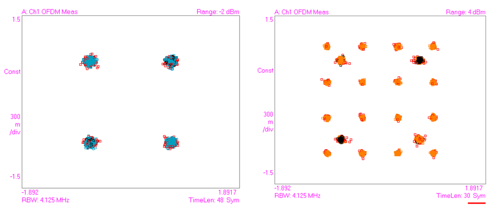
The Radio over Fiber (RoF) analyses done at 1,300 nm are reported in Figure 22. Three standards have been tested as presented in Figure 20 in order to demonstrate the capacities and robustness of the multi-services concept for several applications (radiocellular WCDMA, WLAN IEEE802.11g and WPAN Wimedia BG1). In each case, EVM values below the standard requirement have been achieved when the fiber length is limited to 100 m. As demonstrated during the digital analyses, the GigaPOF62-SR exhibits better results owing to the reduced core diameter mismatching, in spite of a higher attenuation (as compared to the Lucina-X).
Figure 22 clearly illustrates the penalties induced by the WDM devices when the IEEE802.11g transmission is achieved through the two PFGI-POF being tested. A higher distance could be reached with the GigaPOF62-SR to extend the indoor coverage of wireless signals (200 m up to 300 m) using such a system topology as compared to the Lucina-X PFGI-POF. Nevertheless, the 10 GbE transmission seems to be limited to 100 m owing to the PFGI-POF attenuation in spite of a very promising bandwidth length product. The high attenuation of the fiber being tested clearly impacted the optical power budget of the 10 GbE link.
3. Conclusions
The paper has highlighted the capacities of the PFGI-POF able to support both the transmission of the high data rate baseband standard (up to 10 Gbps) and the radiofrequency signal with RoF technology. It is clear that the fiber length is restricted to 100 m owing to the multimode behavior of the PFGI-POF which limits the fiber modal bandwidth both in the radio and digital domains at 850 nm and 1,300 nm. The penalties inherent to the fiber have been exhibited in the two domains and high transmission quality has been obtained for the transmitted signal. The multi-services concept has been demonstrated with such fibers. Even if the 120 μm based PFGI-POF seems to be penalized due to the core diameter, the simultaneous transmission of a 10 GbE signal and a RF wireless signal respectively at 850 nm and 1,300 nm, with commercial off the shelf devices, has been achieved through 100 m of PFGI-POF (Lucina X and GigaPO62-SR). The results obtained with such topology clearly demonstrated the bandwidth capacities of the PFGI-POF for the deployment of small office/home office network based on the multi-services concept.


| IEC | Core/cladding diameters (μm) | α at 850 nm (dB/km) | α at 1,300 nm (dB/km) | Modal bandwidth at 850 nm (MHz km) | NA | |
|---|---|---|---|---|---|---|
| Lucina | A4g | 120/490 | 18 | 18 | 350 | 0.185 |
| Lucina-X | A4g | 120/490 | 18 | 18 | 350 | 0.185 |
| GigaPOF-50SR | 50/490 | 40 | 40 | 300 | 0.19 | |
| GigaPOF-62SR | A4h? | 62.5/490 | 40 | 40 | 300 | 0.19 |
| GigaPOF-120SR | A4g | 120/490 | 40 | 40 | 300 | 0.185 |
| PMMF Type | GigaPOF-120SR | Lucina | GigaPOF-62SR | GigaPOF-50SR |
|---|---|---|---|---|
| Measured DMD (ps/m) | 2.7 | 3.97 | 3.15 | 3.68 |
| From Chromis Fiber optics Manufacturer | From AGC Manufacturer | ||||
|---|---|---|---|---|---|
| Fiber diameter | 50 μm | 62.5 μm | 120 μm | 120 μm | |
| With EDC | - | 3.5 | 4 | 4 | 3.5 |
| Without EDC | - | 6 | - | >9 | 9 |
Acknowledgments
This work was supported by the ERDF (European Regional Development Fund) and by the Nord-Pas-de-Calais Region (France).
References
- Kamisaka, T.; Kuri, T.; Kitayama, K. Simultaneous Modulation and Fiber-Optic Transmission of 10-Gb/s Baseband and 60-GHz-Band Radio Signals on a Single Wavelength. IEEE Trans. Microwave Theory Tech. 2001, 49, 2013–2017. [Google Scholar]
- Gasulla, I.; Capmany, J. Simultaneous Baseband and Radio over Fiber Signal Transmission over a 5 km MMF Link. Proceedings of IEEE MWP/APMP 2008, Gold Coast, Australia, 9 September–3 October 2008; pp. 209–212.
- Lethien, C.; Loyez, C.; Vilcot, J.P.; Rolland, P.A. Multi-Service Applications on High Modal Bandwidth Glass Multimode Fiber. IET Electron. Lett. 2009, 45, 951–952. [Google Scholar]
- Lethien, C.; Loyez, C.; Vilcot, J.P.; Rolland, P.A. Potential of the High Modal Bandwidth OM4 Glass Multimode Fiber for the Multi-Services Concept. Opt. Commun. 2011, 284, 585–589. [Google Scholar]
- Koike, Y. Status of POF in Japan. Proceedings of POF'1996, Paris, France, October 1996; pp. 1–8.
- Murofushi, M. Low Loss Perfluorinated POF. Proceedings of POF'1996, Paris, France, October 1996; pp. 17–23.
- van den Boom, H.P.A.; Li, W.; van Bennekom, P.K.; Monroy, I.T.; Khoe, G.D. High-Capacity Transmission over Polymer Optical Fibre. IEEE J. Sel. Top. Quantum Electron. 2001, 7, 461–470. [Google Scholar]
- Ishigure, T.; Horibe, A.; Nihei, E.; Koike, Y. High-Bandwidth, High-Numerical Aperture Graded-Index Polymer Optical Fiber. IEEE/OSA J. Lightw. Technol. 1995, 13, 1686–1691. [Google Scholar]
- Koike, Y. Progress in Plastic Fiber Technology. Proceedings of OFC'1997, Dallas, TX, USA, 16–21 February 1997; pp. 103–108.
- Koike, Y.; Ishigure, T.; Nihei, E. High-Bandwidth Graded-Index Polymer Optical Fiber with High-Temperature Stability. IEEE/OSA J. Lightw. Technol. 2002, 20, 1443–1448. [Google Scholar]
- van Duijnhoven, F.G.H. Gradient Refractive Index Polymers Produced in a Centrifugal Field: Preparation, Characterisation and Properties. Ph.D. Thesis, Proefschrift, Technische Universiteit Eindhoven, Eindhoven, The Netherlands, 1999. [Google Scholar]
- White, W. New Perspectives on the Advantages of GI-POF. Proceedings of POF' 2005, Hong Kong, China, September 2005.
- Bennett, M.; Flatman, A.; Tolley, B. Broad Market Potential of 10 Gb/s Ethernet on FDDI Grade MM Fiber, IEEE802.3 2004; Available online: http://www.ieee802.org/3/tutorial/mar04/10GMMF_SG_v031604a.pdf (accessed on 28 June 2011).
- Product Specifications—Sectional Specification for Category A4 Multimode Fibres, 2nd ed. Standard IEC 60793-2-40. 2006. Available online: http://webstore.iec.ch/webstore/webstore.nsf/artnum/035855 (accessed on 28 June 2011).
- FOTP-58—Core Diameter Measurement of Graded-Index Optical Fibers, Method C, Option 2; EIA/TIA-455-58A; November; 1990.
- FOTP-43—Output Near-Field Radiation Pattern Measurement of Optical Waveguide Fibers; EIA-455-43; December; 1984.
- Lethien, C.; Loyez, C.; Vilcot, J.P.; Goffin, A. Differential Mode Delay Measurements of Fluorinated Graded Index Polymer Optical Fiber. IEEE Photon. Technol. Lett. 2008, 20, 1584–1586. [Google Scholar]
- Lethien, C.; Loyez, C.; Vilcot, J.P.; Rolland, N.; Rolland, P.A. Potential of the Polymer Optical Fibers Deployed in a 10Gbps Small Office/Home Office Network. Opt. Express 2008, 16, 11266–11274. [Google Scholar]
- Datasheets of the Lucina Fiber; Asahi Glass Co. Ltd.: Tokyo, Japan, 2009. Available online: http://www.agc.co.jp/english/rd_e/e_lucina.html (accessed on 28 June 2011).
- Giaretta, G.; White, W.; Wegmuller, M.; Onishi, T. High-Speed (11 Gbit/s) Data Transmission Using Perfluorinated Graded-Index Polymer Optical Fibers for Short Interconnects (<100 m). IEEE Photon. Technol. Lett. 2000, 12, 347–349. [Google Scholar]
- Description of the Phyworks Technology. Available online: http://www.maxim-ic.com/products/ (accessed on 28 June 2011).
- Polley, A.; Gandhi, R.J.; Ralph, S.E. 40Gbps Links Using Plastic Optical Fiber. Proceedings of Optical Fiber Communication and the National Fiber Optic Engineers Conference, OFC/NFOEC 2007, Anaheim, CA, USA, 25–29 March 2007; pp. 1–3.
- Polley, A.; Ralph, S.E. 100 m, 40 Gb/s Plastic Optical Fiber Link. Proceedings of Optical Fiber Communication and the National Fiber Optic Engineers Conference, OFC/NFOEC 2008, San Diego, CA, USA, 24–28 February 2008; pp. 1–3.
- Schöllmann, S.; Rosenkranz, W.; Wree, C.; Joshi, A. First Experimental Transmission over 50 m GI-POF at 40 Gb/s for Variable Launching Offsets. Proceedings of the 33rd European Conference on Optical Communications, Berlin, Germany, 16–20 September 2007.
- Peng, H.C.; Su, H.S.; Lu, H.H.; Li, C.Y.; Peng, P.C.; Wu, S.H.; Chang, C.H. Hybrid CATV/16-QAM OFDM in-Building Networks over SMF and GI-POF Transport. Opt. Express 2011, 19, 9575–9581. [Google Scholar]
- Lethien, C.; Goffin, A.; Vilcot, J.P.; Loyez, C. Radio over Fibre Systems Using Perfluorinated Graded Index Polymer Optical Fibre. Microwave Opt. Technol. Lett. 2006, 48, 1197–1199. [Google Scholar]
- Lethien, C.; Loyez, C.; Vilcot, J.P. Potentials of Radio over Multimode Fiber Systems for the in-Buildings Coverage of Mobile and Wireless LAN Applications. IEEE Photon. Technol. Lett. 2005, 17, 2793–2795. [Google Scholar]
- Ishigure, T.; Makino, K.; Tanaka, S.; Koike, Y. High-Bandwidth graded index polymer optical fiber enabling power penalty-free gigabit data transmission. IEEE/OSA J. Lightw. Technol. 2003, 21, 2923–2930. [Google Scholar]
- Lethien, C.; Loyez, C.; Vilcot, J.P.; Kassi, R.; Rolland, N.; Sion, C.; Rolland, P.A. Review of Glass and Polymer Multimode Fibers Used in a Wimedia UltraWide Band MB-OFDM Radio over Fiber System. IEEE/OSA J. Lightw. Technol. 2009, 27, 1320–1331. [Google Scholar]
- Lethien, C.; Loyez, C.; Vilcot, J.P.; Rolland, P.A. High Modal Bandwidth Glass Multimode Fibers Used for the Simultaneous Transmission of 10GbE and Band Group 5 MB-OFDM Ultra-Wide Band Signals. Proceedings of the European Workshop on Photonic Solutions for Wireless, Access and in-House Networks, Duisburg, Germany, 18–20 May 2009.
© 2011 by the authors; licensee MDPI, Basel, Switzerland. This article is an open access article distributed under the terms and conditions of the Creative Commons Attribution license (http://creativecommons.org/licenses/by/3.0/).
Share and Cite
Lethien, C.; Loyez, C.; Vilcot, J.-P.; Rolland, N.; Rolland, P.A. Exploit the Bandwidth Capacities of the Perfluorinated Graded Index Polymer Optical Fiber for Multi-Services Distribution. Polymers 2011, 3, 1006-1028. https://doi.org/10.3390/polym3031006
Lethien C, Loyez C, Vilcot J-P, Rolland N, Rolland PA. Exploit the Bandwidth Capacities of the Perfluorinated Graded Index Polymer Optical Fiber for Multi-Services Distribution. Polymers. 2011; 3(3):1006-1028. https://doi.org/10.3390/polym3031006
Chicago/Turabian StyleLethien, Christophe, Christophe Loyez, Jean-Pierre Vilcot, Nathalie Rolland, and Paul Alain Rolland. 2011. "Exploit the Bandwidth Capacities of the Perfluorinated Graded Index Polymer Optical Fiber for Multi-Services Distribution" Polymers 3, no. 3: 1006-1028. https://doi.org/10.3390/polym3031006