Microscopic and Spectroscopic Investigation of Poly(3-hexylthiophene) Interaction with Carbon Nanotubes

Abstract
: The inclusion of carbon nanotubes in polymer matrix has been proposed to enhance the polymer's physical and electrical properties. In this study, microscopic and spectroscopic techniques are used to investigate the interaction between poly(3-hexylthiophene) (P3HT) and nanotubes and the reciprocal modification of physical properties. The presence of P3HT-covered nanotubes dispersed in the polymer matrix has been observed by atomic force microscopy and transmission electron microscopy. Then, the modification of P3HT optical properties due to nanotube inclusion has been evidenced with spectroscopic techniques like absorption and Raman spectroscopy. The study is completed with detailed nanoscale analysis by scanning probe techniques. The ordered self assembly of polymer adhering on the nanotube is unveiled by showing an example of helical wrapping of P3HT. Scanning tunneling spectroscopy study provides information on the electronic structure of nanotube-polymer assembly, revealing the charge transfer from P3HT to the nanotube.1. Introduction
The discovery of charge conduction in polymers by Bolto et al. in 1963 [1] and the synthesis of a conductive polymer by Shirikawa et al. in 1977 [2], demonstrated the possibility of employing new organic materials in electronic applications. Conductive polymers or organic semiconductors rapidly conquered several fields of electronic application, being employed since 1990s as active materials for Light Emitting Diodes (LED) [3,4] and transistors [5,6]. Some of the advantages offered by organic semiconductors over inorganic are reduced costs due to easy processability [7,8], tunability [9,10] and improved mechanical properties like lightness, flexibility, etc.
To further improve organic semiconductor properties, compounds based on the inclusion of carbon nanotubes (CNTs) in the polymer matrix have been proposed, evidencing an enhancement of electrical [11,12] and mechanical properties [13] of the resultant composite. The improvement has been associated with carbon nanotubes extraordinary properties [14-18]. Carbon nanotubes have also been introduced in organic semiconductors layers as an alternative to buckminsterfullerene C60 derivatives for bulk heterojunction photovoltaic devices [19,20]. The expectation was to improve electron transport through the percolating network of highly conducting carbon nanotubes in the polymer matrix. In these mixtures, once the photon is absorbed in the polymer, the high electric field at the carbon nanotubes surface is expected to separate the photo-generated carriers. Electrons should transfer to CNTs which are expected to act as an efficient n-type charge carrier acceptor and conductor. To date, high power conversion efficiencies for this type of devices have not been reported yet and CNTs doping has been beneficial only to enhance the efficiency of solar cells based on polymer and fullerenes soluble derivatives [21-23].
In this study we address the main mechanisms of Poly(3-hexylthiophene) (P3HT) and carbon nanotubes interaction by undertaking microscopic and spectroscopic investigation of compounds. Atomic Force Microscopy (AFM) and Transmission Electron Microscopy (TEM) have been employed to image compound films, with nanotubes trapped and embedded inside the polymer matrix. Ultraviolet and visible absorbance (UV-Vis) spectra and Raman spectra have been acquired to investigate the bulk properties of the blends.
In order to understand short-range interactions between polymer and nanotubes and to provide key information for the comprehension of the basic mechanisms affecting their bulk properties, an accurate nanoscale analysis has been performed. The structural self-organization of conjugated polymers on nanotube surface has been recently modeled by Gotovac et al. [24] and Chen et al. [25]. The strong π–π bonds interaction is believed to bring the alignment of the polymer backbone along the nanotube axis or along directions with large coiling angles. In the last section of this work, we investigate the P3HT adsorption on CNTs by using Scanning Tunneling Microscopy operating under Ultra High Vacuum conditions (UHV-STM), in order to unveil the self assembled P3HT structure on the nanotube surface and the modification of its electronic and mechanical properties.
2. Experimental
2.1. Composite Preparation
Regio-regular P3HT (RR-P3HT) and multi-wall carbon nanotubes (MWNTs) were purchased from Aldrich whereas double-wall carbon nanotubes (DWNTs) were purchased from Carbolex. RR-P3HT p.n. 445703 regio-regularity was reported greater than 98.5% head-to-tail. MWNTs carbon content was reported higher than 95% and has been assessed at 98% by thermogravimetric analysis (TGA). For DWNTs samples the TGA analysis reported a carbon content of more than 92%.
Initially, CNTs were dispersed in organic solvents like chloroform (CF), chlorobenzene (CB) or dichlorobenzene (DCB). In order to disentangle CNTs clusters we used sonication (output power 50 W), obtaining a stable dispersion after 4–6 h of ultrasound treatment if the concentration of nanotube was 0.1–0.15 mg/mL or lower. The dispersion could last from a few hours to several days depending on the solvent used (typically DCB provides the best dispersion). The polymer was dispersed in the same solvents but in higher concentrations, typically 10–20 mg/mL. The relative content of the two materials, measured by the weight/weight content (w/w), was achieved by controlling the volume of solution added. Mixing was performed by using a combination of sonication and stirring, with sonication stages of 1 h maximum and stirring stages for a minimum of 2 h up to several days while heating the solution at 50 °C. While for nanoscale analysis the final concentration of the blends was not important, the film characterization with AFM and absorption spectroscopy was performed on layers with controlled thickness. For this reason, samples were produced with a final concentration of 20 mg/mL in order to obtain, after a deposition made by spin coating, layer of 80–120 nm.
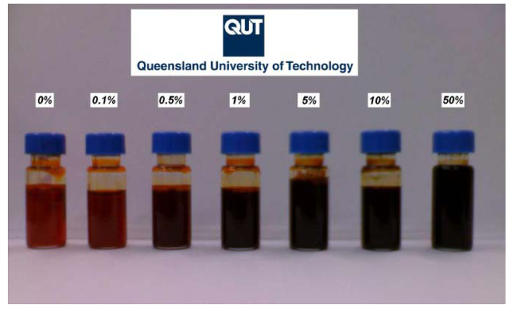
Figure 1 shows an example of the samples made with w/w of P3HT/DWNTs content varying from 0% to 50%. In the latter case, the weight of DWNTs is 50% of the weight of P3HT.
2.2. Experimental Techniques
Atomic force microscopy scans were conducted on a NT-MDT Solver SPM apparatus on films deposited by spin casting on glass. Films were annealed in air at 120 °C to favor polymer reorganization and to reduce surface roughness. Images were collected using AFM contact mode and NT-MDT Si tips CSG01 with typical curvature radius of 6 nm.
Samples for TEM have been firstly deposited by spin casting on glass with the same experimental conditions of AFM samples. Compound covered glasses were then soaked in deionized water to lift up the deposited layer. Water floating films were collected with 300 mesh copper grid and analyzed with a JEOL JEM-1200EX transmission electron microscope with field emission gun operating at 80 kV.
Samples for Raman spectra collection were deposited by drop casting on microscope glass slabs. Spectra were collected with a Renishaw 1000 Raman microscope in which samples were excited with 532 nm diode laser with intensities ranging from 0.01% to 10% of the maximum power (300 mW). Circularly polarized and slightly defocused radiation was used to minimize sample degradation. Spectra were collected from 200 to 4,000 cm−1 calibrated against the 520.5 cm−1 peak of a silicon wafer. Signal-to-noise ratio was maximized by collecting and averaging 6 × 60 second scans. UV-Vis spectra were acquired using Cary 5000 Probe UV-Vis spectrometer on samples deposited by drop casting on glass. Absorbance spectra were collected in the region 200–1,200 nm using 600 nm/min as scan speed. Since the accuracy on the wavelength is lower than 0.1 nm the correspondent accuracy on the wavelength in the analysis range is expected to be lower than 0.3 meV.
Scanning tunneling microscopy and spectroscopy imaging has been performed on samples deposited by drop casting on freshly cleaved Highly Oriented Pyrolitic Graphite (HOPG) by using an Omicron Variable Temperature microscope. Scanning Tunneling Spectroscopy measurements were collected simultaneously to STM images. The tip-sample distance was regulated at the beginning of the scan by the selection of the sample bias voltage and the current set point. On each point of the spectroscopy grid, the scan was stopped, the feedback was disabled and the I-V spectrum was collected varying the sample bias according to the limits selected i.e., −1.5 V < V < 1.5 V.
3. Results and Discussion
3.1. Microscopy Investigation: AFM and TEM
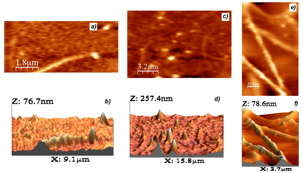
Due to the limited resolution of the instruments used, the microscopic analysis has been conducted on P3HT/MWNTs compounds. In fact, MWNTs exhibit larger structures which can be easily resolved by non-atomic resolution equipment. Figure 2(a) shows an example of AFM imaging of 0.1–1% P3HT/MWNTs compound film. Underneath the film surface, rod-like structures can be easily individuated and correspond to the MWNTs introduced in the polymer matrix.
By observing Figure 2(b), it is possible to associate the bright spots of the 2-D image to nanotubes protruding from the film plane. This consideration is due to the frequent correspondence of the bright spots with tubular structures buried in the polymer layer and also to the absence of bright spots observed in pristine P3HT films. It is important to observe that the shape of the protruding nanotube is affected by the AFM tip convolution effect.
Due to the low MWNTs concentration, all the visible nanotubes visible in Figure 2(c) are isolated, evidencing that the dispersion obtained through the sonication is effective. Nanotube lengths range from 2 to 6 μm while diameters can be estimated in the XY-plane ranging from 200 to 400 nm. This evaluation is affected by a non-negligible error due to P3HT screening of the single tube and the impossibility to individuate smaller tubes buried in the polymer, added to the convolution effect due to the AFM tip size in the range 15–30 nm.
The AFM image reported in Figure 2(e) has been obtained on a thinner film 60–70 nm and at higher magnification and shows a region where nearly free-standing P3HT-covered nanotubes can be observed. A better estimation of the nanotube diameter can be given in this case by analyzing the structures emerging from the XY-plane to a height of 15–30 nm. The 3D visualization of Figure 2(f) highlights the roughness of the P3HT covered carbon nanotube which we associate to the polymer wrapping. This phenomenon, previously reported for other polymers by O'Connell et al. [26], has been observed by our group with scanning probe techniques [27] and confirms the P3HT tendency to adhere on the nanotube surface.
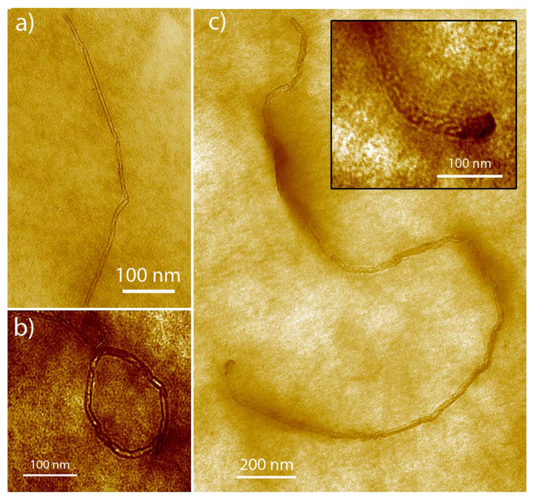
Free-standing 0.1–1% P3HT/MWNT films have been imaged with transmission electron microscopy in order to reach a better resolution with respect to AFM. As reported in Figure 3, the films appear uniform and it is easy to individuate the nanotubes embedded in the polymer matrix. The presence of isolated nanotubes is therefore confirmed through the entire thickness of the layer and not only closer to the film surface as assessed for AFM. In Figure 3, the nanotubes display several of bends and kinks, exhibiting variable diameters. In Figure 3(b) the nanotube is bent enough to form an apparent O-ring shape. The diameters span in the range 20–30 nm matching the previous AFM estimation. Nanotubes lengths range from 590 nm to 3.1 μm for the nanotube in Figure 3(a,c) respectively. Referring to the inset of Figure 3(c), we notice that on the nanotube surface it is possible to observe an ordered polymer structure even if the TEM resolution is too low to allow further considerations.
3.2. Spectroscopic Characterisation: UV-Vis and Raman
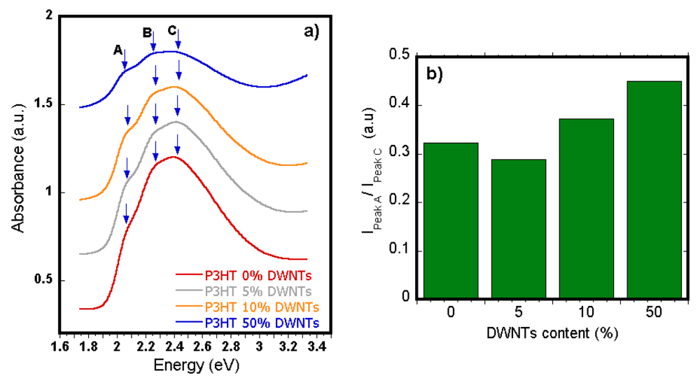
Absorption spectra of P3HT/DWNT compounds deposited by dropcast from CB solution are reported in Figure 4. Pristine P3HT spectrum is characterized by a maximum labeled “C” at 2.42 eV corresponding to 0–2 optical transition [28]. Two other features labeled A and B in the graph occur at 2.02 eV and 2.19 eV respectively points extracted with a second derivative analysis. Both these points are in good agreement with literature results [29]. While the feature B has been related to transition 0-0, the feature A has been attributed to intrachain absorption. The intensity of this peak is related to the degree of planar order of the polymer backbone. The intensity is higher as the number of torsional deformation of the polymer chain is reduced and the P3HT molecule lies on the same plane. In Figure 4(b), by showing the relative intensity of features A with respect to the spectrum maximum, it can be observed that as the carbon nanotube content is increased, the peak relative intensity increases from 0.32 to 0.45 (∼+40%). Therefore the torsional deformation of the P3HT chains is decreased, confirming that the DWNTs play a role in the polymer ordering.
A similar result is found when considering the data in Table 1 which shows a weak red shift of the spectra features. A downshift up to 40 meV or 8 nm is observed for the spectra maximum as the content of DWNTs is raised. This phenomenon has been previously observed and associated with an increase of the conjugation length of the polymer [28,30]. We can therefore conclude that the strong interaction between the two materials is the driving force leading to an increased organization of the polymer chains on the nanotube surface, as already assessed by microscopy studies.
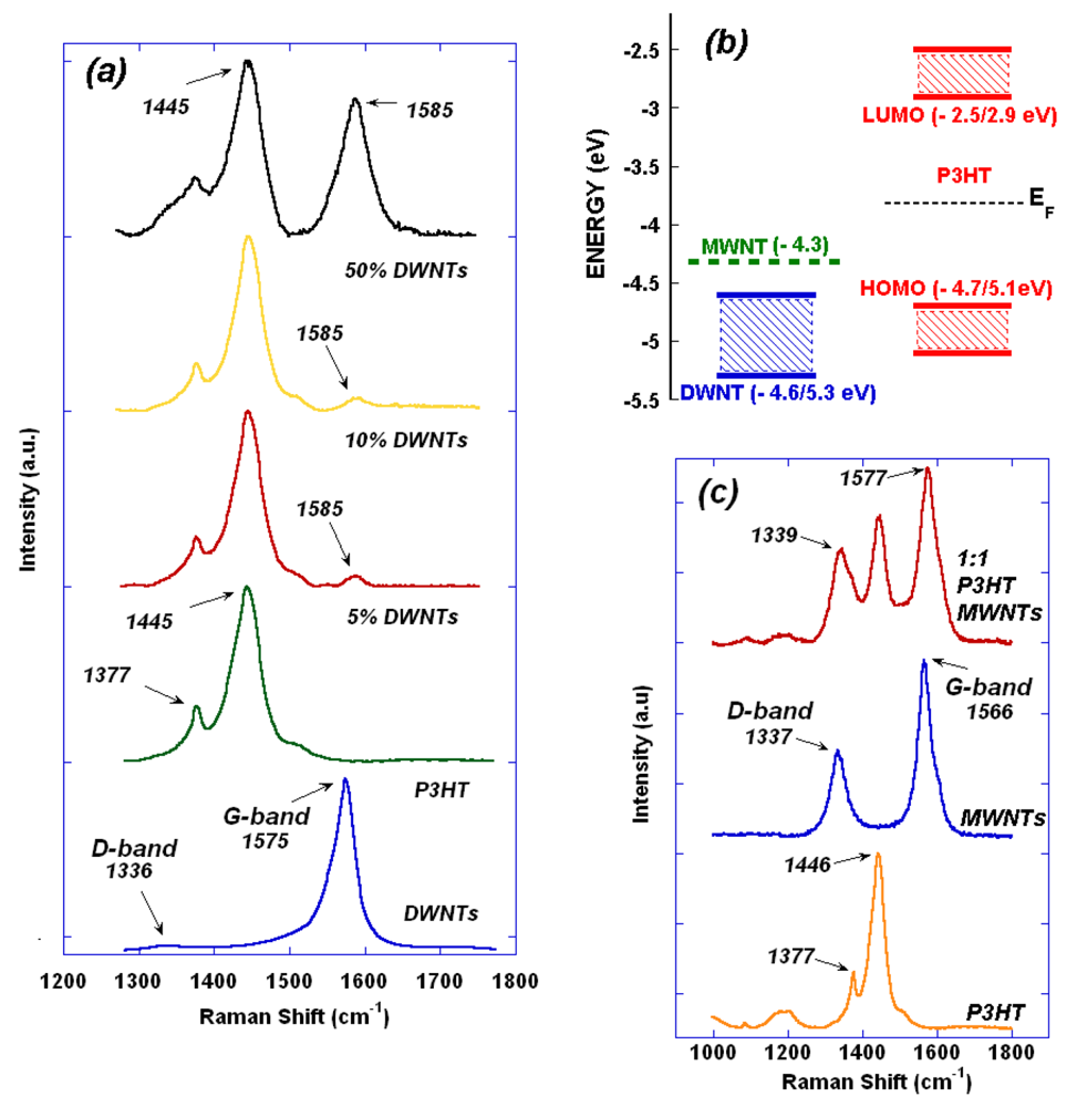
More detail about the spectroscopic characteristic of P3HT/DWNTs and P3HT/MWNTs compounds is provided by Raman spectroscopy, reported in Figure 5. Pristine DWNTs and P3HT spectra show their respective characteristic peaks. For DWNTs two main bands are typically outlined: D band at 1,335 cm−1 related to nanotube defects and G band at 1,575 cm−1 associated with longitudinal and transversal optical vibration of the tubes [31]. The higher intensity of G band with respect to D band highlights the low content of nanotube defects and carbonaceous species. Conversely, P3HT spectra is characterized by two peaks at 1,377 cm−1 and 1,445 cm−1 related to Cβ–Cβ′ stretching 1,377 cm−1 and Cβ+–H bending and Cα=Cβ stretching respectively 1,445 cm−1 [32]. As reported in Figure 5(a), as the content of nanotubes is raised, a peak centered at 1,585 cm−1 is observed.
The peak is related to the G band of DWNTs and presents a considerable up-shift of 10 cm−1. This phenomenon can be related to two main causes: nanotube doping and mechanical restriction of the freedom of C–C vibrations. Considering the doping, an up-shift in the G band can occur if carbon nanotubes act as donor of electron to the material with which they interact [35]. In Figure 5(b) the energy band diagram for pristine isolated P3HT, MWNTs and DWNTs is considered. Double wall carbon nanotubes can be semiconducting or metallic therefore the respective energy levels are represented with a dashed band including all the cases. Using this simple visual model, it can be observed that despite the type of nanotube considered, the electron migration from the nanotube to the polymer is unlikely to occur due to the relative position of the Fermi level. Conversely, the restriction of C–C vibration can be related to nanotube polymer non-covalent interaction via π–π or CH–π. The G-band upshift reported for DWNTs is observed also for MWNT compounds: Figure 5(c) shows the Raman spectra of pristine polymer, pristine MWNTs and 1:1 w/w compounds, with a measured shift of 11 cm−1.
3.3. Nanoscale Investigation: STM and STS
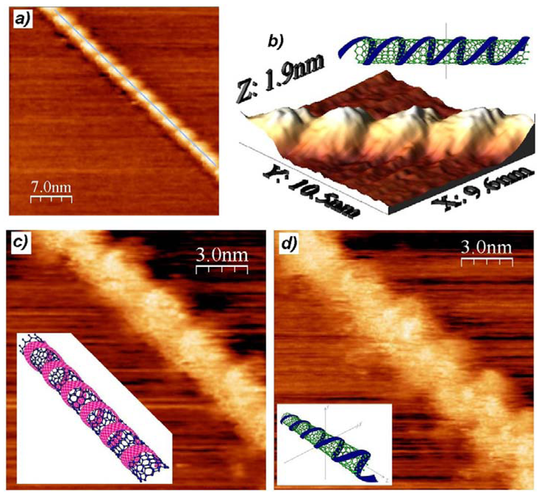
Microscopy and spectroscopy bulk techniques have demonstrated that P3HT strongly interacts with the nanotube surface and consequently the physical and optical properties of the polymer change. Further analyses at the nanoscale can confirm what was revealed in composites characterization and can provide experimental evidences of the interaction previously hypothesized. Figure 6 show a P3HT wrapped carbon nanotube imaged with UHV-STM. Since the nanotube is not visible, it is assumed it is a MWNT since this species has been used in the preparation of the compound. The polymer structure coils the nanotube surface for more than 35 nanometers and presents a high degree of order as the periodic wrapping can be observed as a replicating assembly over the whole structure. We observe that the P3HT tendency of forming highly-ordered structures on the nanotube surface reinforces the UV-Vis considerations, which related the absorbance red shift to a higher degree of order of the polymer. The period of the polymer structure is evaluated by calculating the Fourier transform of the structure profile evidenced with a cyan line in Figure 6(a) and results 3.0 ± 0.1 nm.
Figure 6(b) shows the 3-D image of a section of the wrapped nanotube, from which it is possible to have a clear understanding of the polymer coverage. The P3HT self-organization is helical but in this case, remarkably, the coiling shows a variable coiling angle. As can be seen in the inset of Figure 6(b) where the structure has been mathematically reconstructed, the periodic variation of the coiling angle eliminates the rotational symmetry of the covering structure. Nevertheless, the inter-coil distance along the nanotube main axis does not vary as can be observed in the other examples of Figure 6. Rotational symmetry would be present for a constant coiling angle as reported in our previous work [27]. Exploring the nanotube along its main axis, it has been possible to image the different patterns of the polymer coverage, since the P3HT structure rotated around along the nanotube. These cases are shown in Figure 6(c,d) and demonstrate that the polymer self-organization appears to have different shapes according to the observation point. Referring to our previous results, we can speculate that the non-constant coiling angle could be a result of the mismatch between the underlying carbon nanotube's chirality and the energy minima of the P3HT self-assembled structure. Recent theoretical studies based on classical molecular dynamics simulations [36] show that the P3HT wraps around the single-wall carbon nanotubes (SWNTs) in a number of different conformations, including helices, bundles, and more elongated conformations that maximize planar stacking, matching perfectly the above experimental observations. The simulations reveal that the 1-dimensional 1D nature of the carbon nanotubes plays an important templating role in the polymer attachment.
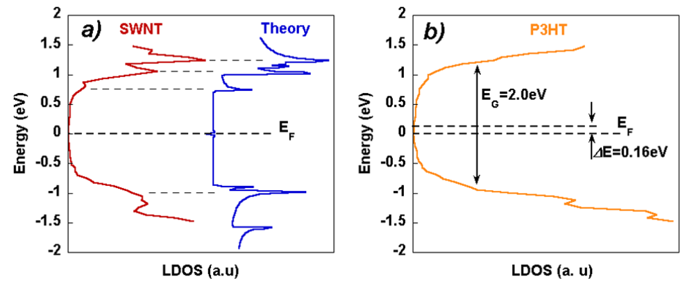
Figure 7(a) shows the local density of states (LDOS) of a P3HT coil-wrapped (15,0) single wall nanotube measured with Scanning Tunneling Spectroscopy (this study is based on our previously published results, see Ref. [37] for further details). The experimental curve, collected on a non-wrapped section of the nanotube is compared with the literature available LDOS theoretical curve [38]. It must be noticed that since the LDOS is centered on the 0 V value, no trace of charge transfer can be observed between the nanotube and substrate HOPG. This result confirms the correspondence between the Fermi energy levels of the two materials SWNT and HOPG.
Conversely, when the LDOS is measured on a P3HT wrapped section of the same nanotube, as reported in Figure 7(b), it is possible to observe that a shift of the polymer band gap towards the highest occupied molecular orbital (HOMO) appears in the differential conductance curve. The shift of ΔE = 0.16 eV can be related to negative charge transfer from P3HT to the nanotube that can be therefore referred as a donor-acceptor system. Electron transfer to nanotubes can cause a further shift of the Fermi energy of the nanotube towards the vacuum level [39]. It has also been identified as one of the factors reducing the possibility of charge separation in P3HT/CNTs based devices [40].
The observed charge transfer provides a better understanding of the Raman spectra reported previously. In fact, it must be observed that an electron migration to CNTs causes a weakening of C–C bonds on the nanotube surface and a down-shift of the G band in the Raman spectra [35]. Therefore, the opposite up-shift observed in Figure 5(a,c) furthermore reinforces the hypothesis that when P3HT wraps the nanotube, one of the phenomena occurring is the restriction of C–C vibration modes due to the π–π interaction between the carbon atoms of P3HT and CNTs.
Polymer's electron transfer to carbon nanotubes and mechanical restriction of the nanotube structure elastic vibrational are expected to have important consequences on the CNTs properties. Once entrapped in P3HT matrix, carbon nanotubes properties are altered with inevitable consequence on device performance.
4. Conclusion
The strong interaction between carbon nanotubes and P3HT has emerged by analyzing the compounds with several investigation techniques. AFM images showed the adhesion of P3HT on the nanotube surface where TEM analysis resolved polymer ordered structures. Spectroscopy analyses confirmed strong chemical bonding able to modify P3HT and CNTs Raman spectra and polymer conjugation order enhancement related to UV-Vis features red-shift. The results obtained for the bulk are matched by high resolution STM imaging of the polymer structures, showing a clear ordering on the nanotube surface. These data have been recently confirmed by a classical molecular dynamics study, demonstrating that the wrapping structures imaged by our microscopic studies are amongst the possible arrangements minimizing the total energy of the system. The investigation of the electronic structure of the polymer-nanotube assembly has unveiled the local charge transfer between the two materials donor–acceptor interaction and the relative shift of the Fermi's energy level. This circumstance clarifies the interpretation of the observed Raman up-shift of the characteristic carbon nanotube G-band. A better understanding of the nanotubes properties once they are entrapped in the polymer matrix is of crucial importance to achieve effective improvement of performance in electronic devices and solar cells. Further investigation is underway.


| Sample | Maximum eV | Contributions eV | ||
|---|---|---|---|---|
| P3HT | 2.42 | 2.19 | 2.02 | |
| P3HT + 5%DWNTs | 2.43 | 2.20 | 2.00 | |
| P3HT + 10%DWNTs | 2.41 | 2.19 | 2.00 | |
| P3HT + 50%DWNTs | 2.38 | 2.18 | 2.00 | |
Acknowledgments
M.G. is thankful to Karsten Krueger for TEM measurement preparation and to Deborah J. Stenzel for the invaluable help in the film characterization. All authors acknowledge the contribution of the Queensland Government through the NIRAP project “Solar Powered Nanosensors”.
References
- Bolto, B.A.; McNeill, R.; Weiss, D.E. Electronic Properties of Polypyrrole. Aust. J. Chem. 1963, 16, 1090–1103. [Google Scholar]
- Shirakawa, H.; Louis, E.J.; MacDiarmid, A.G.; Chiang, C.K.; Heeger, A.J. Synthesis of Electrically Conducting Organic Polymers: Halogen Derivatives of Polyacetylene, (CH)x. J. Chem. Soc.: Chem. Commun. 1977. [Google Scholar] [CrossRef]
- Burroughes, J.H.; Bradley, D.D.C.; Brown, A.R.; Marks, R.N.; Mackay, K.; Friend, R.H.; Burns, P.L.; Holmes, A.B. Light-Emitting Diodes Based on Conjugated Polymers. Nature 1990, 347, 539–541. [Google Scholar]
- Greenham, N.C.; Moratti, S.C.; Bradley, D.D.C.; Friend, R.H.; Holmes, A.B. Efficient Light-Emitting Diodes Based on Polymers with High Electron Affinities. Nature 1993, 365, 628–630. [Google Scholar]
- Dodabalapur, A.; Torsi, L.; Katz, H.E. Organic Transistors: Two-Dimensional Transport and Improved Electrical Characteristics. Science 1995, 268, 270–271. [Google Scholar]
- Dimitrakopoulos, C.D.; Purushothaman, S.; Kymissis, J.; Callegari, A.; Shaw, J.M. Low-Voltage Organic Transistors on Plastic Comprising High-Dielectric Constant Gate Insulators. Science 1999, 283, 822–824. [Google Scholar]
- Bao, Z.; Dodabalapur, A.; Lovinger, A.J. Soluble and Processable Regioregular Poly(3-hexylthiophene) for Thin Film Field-Effect Transistor Applications with High Mobility. Appl. Phys. Lett. 1996, 69, 4108–4110. [Google Scholar]
- Li, G.; Shrotriya, V.; Huang, J.; Yao, Y.; Moriarty, T.; Emery, K.; Yang, Y. High-Efficiency Solution Processable Polymer Photovoltaic Cells by Self-Organization of Polymer Blends. Nat. Mater. 2005, 4, 864–868. [Google Scholar]
- Liu, B.; Yu, W.-L.; Lai, Y.-H.; Huang, W. Blue-Light-Emitting Fluorene-Based Polymers with Tunable Electronic Properties. Chem. Mater. 2001, 13, 1984–1991. [Google Scholar]
- Zhang, X.; Jenekhe, S.A. Electroluminescence of Multicomponent Conjugated Polymers. 1. Roles of Polymer/Polymer Interfaces in Emission Enhancement and Voltage-Tunable Multicolor Emission in Semiconducting Polymer/Polymer Heterojunctions. Macromolecules 2000, 33, 2069–2082. [Google Scholar]
- Musumeci, A.W.; Silva, G.G.; Liu, J.-W.; Martens, W.N.; Waclawik, E.R. Structure and Conductivity of Multi-Walled Carbon Nanotube/Poly(3-hexylthiophene) Composite Films. Polymer 2007, 48, 1667–1678. [Google Scholar]
- McNally, T.; Potschke, P.; Halley, P.; Murphy, M.; Martin, D.; Bell, S.E.J.; Brennan, G.P.; Bein, D.; Lemoine, P.; Quinn, J.P. Polyethylene Multiwalled Carbon Nanotube Composites. Polymer 2005, 46, 8222–8232. [Google Scholar]
- Cadek, M.; Coleman, J.N.; Barron, V.; Hedicke, K.; Blau, W.J. Morphological and Mechanical Properties of Carbon-Nanotube-Reinforced Semicrystalline and Amorphous Polymer Composites. Appl. Phys. Lett. 2002, 81, 5123–5125. [Google Scholar]
- Dalton, A.B.; Collins, S.; Munoz, E.; Razal, J.M.; Ebron, V.H.; Ferraris, J.P.; Coleman, J.N.; Kim, B.G.; Baughman, R.H. Super-Tough Carbon-Nanotube Fibres. Nature 2003, 423, 703–703. [Google Scholar]
- Ebbesen, T.W.; Lezec, H.J.; Hiura, H.; Bennett, J.W.; Ghaemi, H.F.; Thio, T. Electrical Conductivity of Individual Carbon Nanotubes. Nature 1996, 382, 54–56. [Google Scholar]
- Iijima, S.; Brabec, C.; Maiti, A.; Bernholc, J. Structural Flexibility of Carbon Nanotubes. J. Chem. Phys. 1996, 104, 2089–2092. [Google Scholar]
- Kim, P.; Shi, L.; Majumdar, A.; McEuen, P.L. Thermal Transport Measurements of Individual Multiwalled Nanotubes. Phys. Rev. Lett. 2001, 87, 215502. [Google Scholar]
- Yu, M.-F.; Lourie, O.; Dyer, M.J.; Moloni, K.; Kelly, T.F.; Ruoff, R.S. Strength and Breaking Mechanism of Multiwalled Carbon Nanotubes under Tensile Load. Science 2000, 287, 637–640. [Google Scholar]
- Kymakis, E.; Amaratunga, G.A.J. Single-Wall Carbon Nanotube/Conjugated Polymer Photovoltaic Devices. Appl. Phys. Lett. 2002, 80, 112–114. [Google Scholar]
- Geng, J.; Zeng, T. Influence of Single-Walled Carbon Nanotubes Induced Crystallinity Enhancement and Morphology Change on Polymer Photovoltaic Devices. J. Amer. Chem. Soc. 2006, 128, 16827–16833. [Google Scholar]
- Kymakis, E.; Kornilios, N.; Koudoumas, E. Carbon Nanotube Doping of P3HT: PCBM Photovoltaic Devices. J. Phys. D: Appl. Phys. 2008, 41, 165110. [Google Scholar]
- Wu, M.-C.; Lin, Y.-Y.; Chen, S.; Liao, H.-C.; Wu, Y.-J.; Chen, C.-W.; Chen, Y.F.; Su, W.F. Enhancing Light Absorption and Carrier Transport of P3HT by Doping Multi-Wall Carbon Nanotubes. Chem. Phys. Lett. 2009, 468, 64–68. [Google Scholar]
- Kuila, B.K.; Park, K.; Dai, L. Soluble P3HT-Grafted Carbon Nanotubes: Synthesis and Photovoltaic Application. Macromolecules 2010, 43, 6699–6705. [Google Scholar]
- Gotovac, S.; Honda, H.; Hattori, Y.; Takahashi, K.; Kanoh, H.; Kaneko, K. Effect of Nanoscale Curvature of Single-Walled Carbon Nanotubes on Adsorption of Polycyclic Aromatic Hydrocarbons. Nano Lett. 2007, 7, 583–587. [Google Scholar]
- Chen, F.; Wang, B.; Chen, Y.; Li, L.-J. Toward the Extraction of Single Species of Single-Walled Carbon Nanotubes Using Fluorene-Based Polymers. Nano Lett. 2007, 7, 3013–3017. [Google Scholar]
- O'Connell, M.J.; Boul, P.; Ericson, L.M.; Huffman, C.; Wang, Y.H.; Haroz, E.; Kuper, C.; Tour, J.; Ausman, K.D.; Smalley, R.E. Reversible Water-Solubilization of Single-Walled Carbon Nanotubes by Polymer Wrapping. Chem. Phys. Lett. 2001, 342, 265–271. [Google Scholar]
- Giulianini, M.; Waclawik, E.R.; Bell, J.M.; De Crescenzi, M.; Castrucci, P.; Scarselli, M.; Motta, N. Regioregular Poly(3-hexyl-thiophene) Helical Self-Organization on Carbon Nanotubes. Appl. Phys. Lett. 2009, 95, 013304–013303. [Google Scholar]
- Trznadel, M.; Pron, A.; Zagorska, M.; Chrzaszcz, R.; Pielichowski, J. Effect of Molecular Weight on Spectroscopic and Spectroelectrochemical Properties of Regioregular Poly(3-hexylthiophene). Macromolecules. Macromolecules 1998, 31, 5051–5058. [Google Scholar]
- Brown, P.J.; Thomas, D.S.; Kohler, A.; Wilson, J.S.; Kim, J.S.; Ramsdale, C.M.; Sirringhaus, H.; Friend, R. Effect of Interchain Interactions on the Absorption and Emission of Poly(3-hexylthiophene). Phys. Revi. B 2003. [Google Scholar] [CrossRef]
- Hotta, S.; Rughooputh, S.D.D.V.; Heeger, A.J.; Wudl, F. Spectroscopic Studies of Soluble Poly(3-alkylthienylenes). Macromolecules 2002, 20, 212–215. [Google Scholar]
- Dresselhaus, M.S.; Dresselhaus, G.; Hofmann, M. The Big Picture of Raman Scattering in Carbon Nanotubes. Vib. Spectrosc. 2007, 45, 71–81. [Google Scholar]
- Baibarac, M.; Lapkowski, M.; Pron, A.; Lefrant, S.; Baltog, I. SERS Spectra of Poly(3-hexylthiophene) in Oxidized and Unoxidized States. J. Raman Spectrosc. 1998, 29, 825–832. [Google Scholar]
- Shan, B.; Cho, K. First-Principles Study of Work Functions of Double-Wall Carbon Nanotubes. Phys. Rev. B Condens. Matter Mater. Phys. 2006, 73, 081401–081404. [Google Scholar]
- Ago, H.; Kugler, T.; Cacialli, F.; Salaneck, W.R.; Shaffer, M.S.P.; Windle, A.H.; Friend, R.H. Work Functions and Surface Functional Groups of Multiwall Carbon Nanotubes. J. Phys. Chem. B 1999, 103, 8116–8121. [Google Scholar]
- Rao, A.M.; Eklund, P.C.; Bandow, S.; Thess, A.; Smalley, R.E. Evidence for Charge Transfer in Doped Carbon Nanotube Bundles from Raman scattering. Nature 1997, 388, 257–259. [Google Scholar]
- Bernardi, M.; Giulianini, M.; Grossman, J.C. Self-Assembly and Its Impact on Interfacial Charge Transfer in Carbon Nanotube/P3HT Solar Cells. ACS Nano 2010, 4, 6599–6606. [Google Scholar]
- Giulianini, M.; Waclawik, E.R.; Bell, J.M.; Scarselli, M.; Castrucci, P.; De Crescenzi, M.; Motta, N. Poly(3-hexyl-thiophene) Coil-Wrapped Single Wall Carbon Nanotube Investigated by Scanning Tunneling Spectroscopy. Appl. Phys. Lett. 2009, 95, 143116. [Google Scholar]
- Akai, Y.; Saito, S. Electronic Structure, Energetics and Geometric Structure of Carbon Nanotubes: A Density-Functional Study. Phys. E 2005, 29, 555–559. [Google Scholar]
- Zhao, J.; Han, J.; Lu, J.P. Work Functions of Pristine and Alkali-Metal Intercalated Carbon Nanotubes and Bundles. Phys. Rev. B 2002, 65, 193401. [Google Scholar]
- Kanai, Y.; Grossman, J.C. Role of Semiconducting and Metallic Tubes in P3HT/Carbon-Nanotube Photovoltaic Heterojunctions: Density Functional Theory Calculations. Nano Lett. 2008, 8, 908–912. [Google Scholar]
© 2011 by the authors; licensee MDPI, Basel, Switzerland. This article is an open access article distributed under the terms and conditions of the Creative Commons Attribution license (http://creativecommons.org/licenses/by/3.0/).
Share and Cite
Giulianini, M.; Waclawik, E.R.; Bell, J.M.; Scarselli, M.; Castrucci, P.; De Crescenzi, M.; Motta, N. Microscopic and Spectroscopic Investigation of Poly(3-hexylthiophene) Interaction with Carbon Nanotubes. Polymers 2011, 3, 1433-1446. https://doi.org/10.3390/polym3031433
Giulianini M, Waclawik ER, Bell JM, Scarselli M, Castrucci P, De Crescenzi M, Motta N. Microscopic and Spectroscopic Investigation of Poly(3-hexylthiophene) Interaction with Carbon Nanotubes. Polymers. 2011; 3(3):1433-1446. https://doi.org/10.3390/polym3031433
Chicago/Turabian StyleGiulianini, Michele, Eric R. Waclawik, John M. Bell, Manuela Scarselli, Paola Castrucci, Maurizio De Crescenzi, and Nunzio Motta. 2011. "Microscopic and Spectroscopic Investigation of Poly(3-hexylthiophene) Interaction with Carbon Nanotubes" Polymers 3, no. 3: 1433-1446. https://doi.org/10.3390/polym3031433