1. Introduction
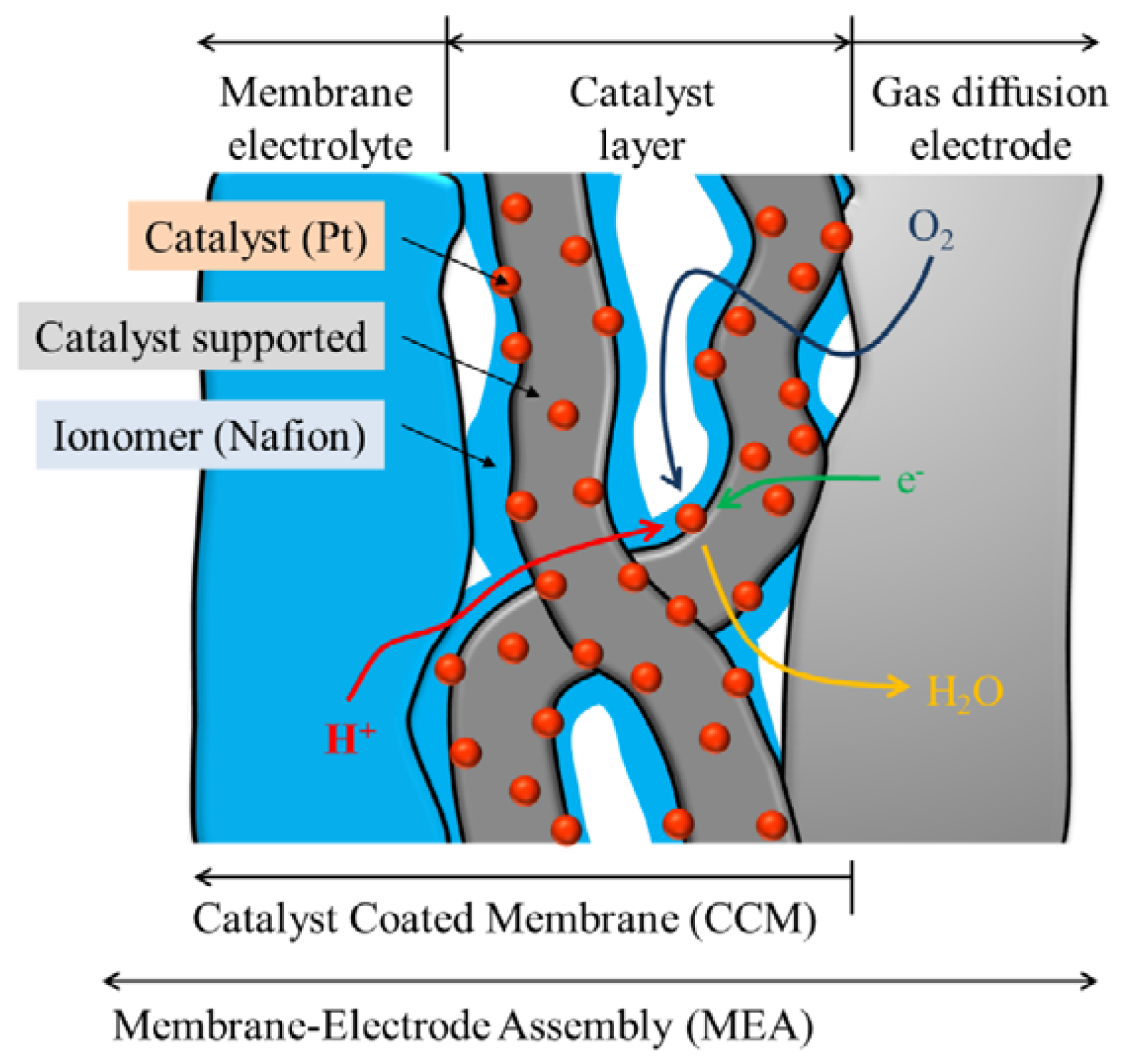
The membrane-electrode assembly (MEA) is used in a polymer electrolyte fuel cell (PEFC). The MEA consists of a catalyst layer, membrane electrolyte, and gas diffusion electrode. The catalyst layer consists of the catalyst and support, electrolyte for the ion conduction path, and space volume for the reaction gases [
1]. The ionomer is used as the electrolyte for proton conduction, and to maintain the catalyst layer as a binder. Many studies have been reported regarding the influence of the ionomer/carbon (I/C) ratio as the electrolyte and binder. They suggested that the optimum I/C ratio existed [
1,
2,
3,
4,
5,
6]. A low ionomer causes a decrease in the proton conduction and a decrease in cell performance when below the optimum I/C ratio. An excess ionomer blocks the space volume and decreases the cell performance when over the optimum I/C ratio. Excess ionomer prevents reactant gases from entering, and the product water from leaving.
Carbon blacks are well known to be a catalyst support for the PEFCs. In recent years, fibrous carbon materials are attracting attention due to their high electric conductivity and water repellency. Carbon blacks have indefinite structures and many fine and deep pores that produce large specific surface areas. Fibrous carbon materials have a small diameter and long length that form large specific surface areas. They have few pores inside, and their surface areas are due to the outside of the fibers. The fibrous structure simultaneously produces both an increasing surface area and increasing repellency. Fibrous carbon materials can contact each other to form a conductive network and provide a good electric conductivity. The carbon nanofilament (CNF) is one of the fibrous carbon materials [
7]. This structure should be favorable for supplying reactant gases and removing the product water. The CNFs have a cup-stack primary structure. The edges of the graphene sheets are exposed to the CNF’s surface. The edges can be supporting sites for the Pt catalyst. CNFs do not require any heat pretreatments or any mechanical pretreatments for supporting the Pt particles on their surfaces [
8].
Different structures of carbon materials should produce different performances for the PEFC and require different I/C ratios. The influence of the I/C ratio should be evaluated when using different carbon materials.
In this study, we prepared MEAs using a Pt catalyst supported on CNFs with different amounts of ionomer, and investigated the influence of the I/C ratio. We indicated the optimum I/C ratio when using CNFs for the PEFC.
2. Experimental Section
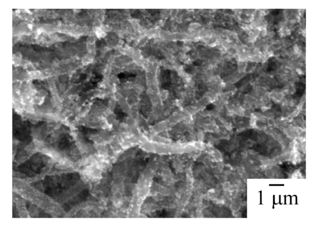
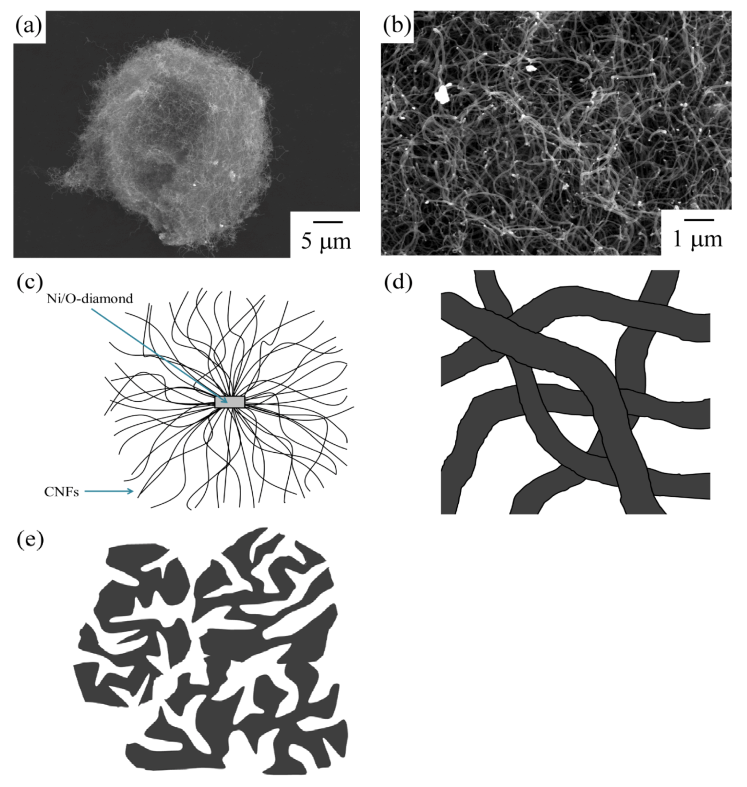
Fibrous carbon materials were used for the catalyst supports. The CNFs were synthesized by the decomposition of methane by a diamond-supported Ni catalyst. The CNFs form a spherical shape (
Figure 1) [
7]. The spherical carbon material was named Marimo carbon. The Marimo carbon consists of many CNFs, and the CNFs are interwoven to form a spherical secondary shape. The Marimo carbon has a sufficient space volume between the CNFs.
Figure 1.
Scanning electron microscope (SEM) image of the (a) spherical shape of the Marimo carbon and (b) interwoven filaments; (c) schematic diagrams of the Marimo carbon; (d) the high magnification diagram of the part of (c); and, (e) schematic diagrams of carbon black.
Figure 1.
Scanning electron microscope (SEM) image of the (a) spherical shape of the Marimo carbon and (b) interwoven filaments; (c) schematic diagrams of the Marimo carbon; (d) the high magnification diagram of the part of (c); and, (e) schematic diagrams of carbon black.
Pt was loaded on the carbon nanofilaments by the modified nanocolloidal method [
9]. The CNFs were mixed in a NaOH solution. Citric acid and H
2PtCl
4 were then added to the CNFs’ suspension. After stirring and ultrasonication, a NaBH
4 solution was added to the suspension with stirring. NaBH
4 reduced the H
2PtCl
4 to yield metallic Pt. The deposited product was separated from the solution. The fine Pt particles were deposited on the CNFs. The deposited Pt particles on the CNFs were observed by scanning electron microscope (SEM) and transmission electron microscope (TEM). The amount of Pt was evaluated by a thermogravimetric analysis (TGA).
The carbon-supported Pt catalyst was used as the electrode of the MEA. The catalyst inks were prepared using the carbon-supported Pt catalyst and various diluted ionomer (Nafion) solutions. The carbon-supported carbon catalyst was suspended in water. Different amounts of a 5 wt% Nafion solution were introduced into the suspension. The different ratio of Nafion to the carbon-supported Pt catalyst was attributed to the ionomer/carbon weight ratio (I/C). The catalyst-coated membranes (CCMs) were produced by spraying of the various catalyst inks and hot pressing. The MEAs were fabricated using the produced CCMs and commercially available gas diffusion electrodes (
Figure 2).
Figure 2.
Schematic diagram of membrane-electrode assembly (MEA).
Figure 2.
Schematic diagram of membrane-electrode assembly (MEA).
Four electrodes were prepared with different catalyst inks (I/C = 0.14, 0.23, 0.46, 0.69) for use as the cathode. An electrode was prepared with the catalyst ink (I/C = 0.46) for the anode. The surface area of the electrode was 5 × 5 cm2. The amount of Pt in the electrode was 5 mg (0.2 mg cm−2).
Cyclic voltammetry (CV) and I-V measurements were used to evaluate the fabricated MEAs. The cathode was purged with nitrogen before the CV measurements. Hydrogen was supplied to the anode during the CV measurements. The CV was measured at room temperature at the scanning rate of 20 mV s−1 in the range of 50–1200 mV vs. RHE. The I-V measurements were conducted at 80 °C. Humidified hydrogen gas (200 mL min−1, 100% RH at 80 °C) was supplied to the anode. Humidified air (200 mL min−1, 100% RH at 70 °C) was supplied to the cathode.
3. Results and Discussion
Figure 3 shows an SEM image of the Pt particles on the CNFs. The Pt particles were highly dispersed on the CNFs by the modified nanocolloidal solution method.
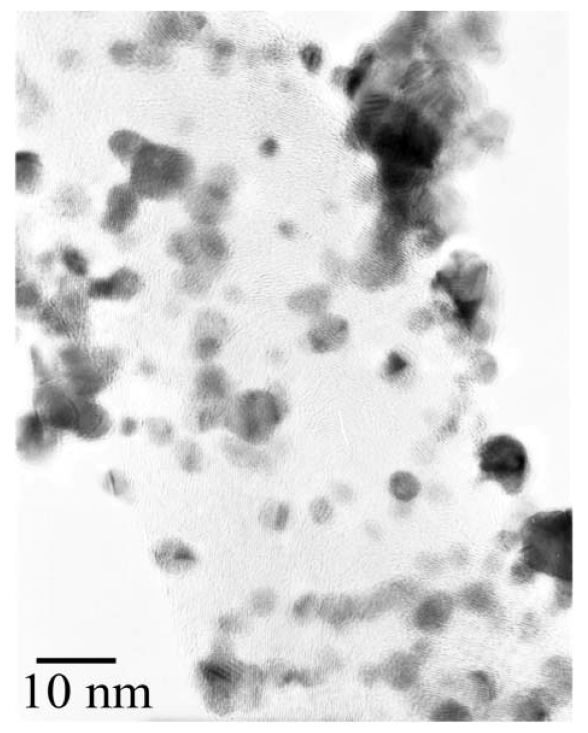
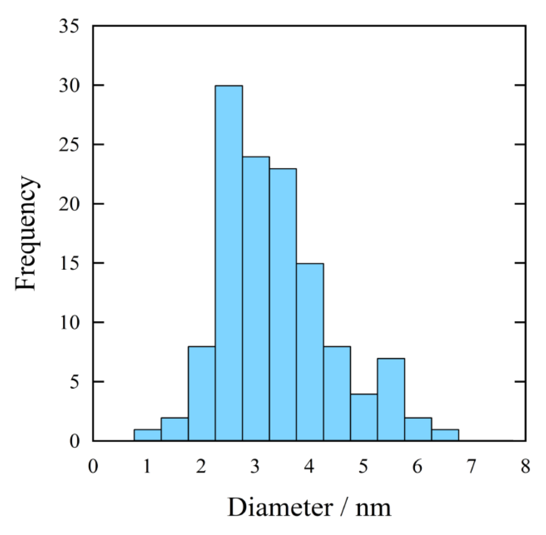
Figure 4 shows a TEM image of the same sample. Most of the Pt particles were highly dispersed on the CNFs in the samples. The average diameter of the Pt particles was evaluated by the randomly selected TEM images. The diameter distribution of 150 Pt particles is illustrated in the histogram of
Figure 5. Most of the Pt particles have 2–5 nm diameters. The previously reported electrodes with Pt particles of 2–3 nm diameters indicated a good performance for the PEFC [
10].
Figure 3.
SEM image of Pt particles on carbon nanofilaments (CNFs). Pt particles were deposited on CNFs by the modified nanocolloidal method.
Figure 3.
SEM image of Pt particles on carbon nanofilaments (CNFs). Pt particles were deposited on CNFs by the modified nanocolloidal method.
Figure 4.
Transmission electron microscope (TEM) image of Pt particles on the CNFs.
Figure 4.
Transmission electron microscope (TEM) image of Pt particles on the CNFs.
Figure 5.
Diameter distribution of Pt particles on the CNFs evaluated by TEM.
Figure 5.
Diameter distribution of Pt particles on the CNFs evaluated by TEM.
The Marimo carbon is composed of fine carbon nanofilaments. Carbon nanofilaments have structures different from other carbonblacks. Carbon nanofilaments have a fibrous structure without fine pores. Carbon blacks have a random structure with many fine pores. The fine pores contribute to the large specific surface areas of the carbon blacks. The active surface area of the PEFC electrodes should be covered with the ionomer. We have to determine the adequate amount of ionomer for the different carbon support materials.
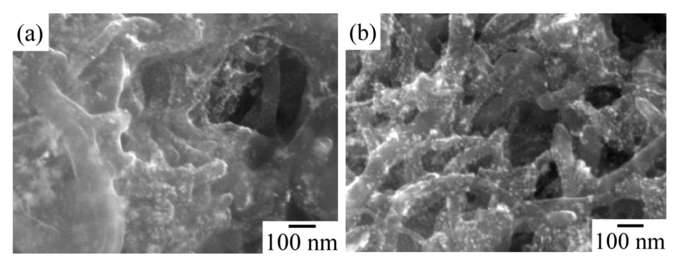
Figure 6 shows SEM images of the catalyst layers in the MEA with different I/C ratios. Image (a) of
Figure 6 indicates in the case of I/C = 0.46 that all the carbon surfaces were covered with the ionomer, and excess ionomers were observed in the space between the carbon nanofilaments. The excess ionomers should close the space volume and interfere with the diffusion of gases. Image (b) of
Figure 6 indicates in the case of I/C = 0.14 that no excess ionomer was observed. In the case of a ratio below I/C = 0.14, the catalyst layer cannot maintain the shape of the electrode. A low amount of ionomer lacked the role of a binder.
Figure 6.
SEM image of Pt particles on the CNFs: (a) I/C = 0.46; (b) I/C = 0.14.
Figure 6.
SEM image of Pt particles on the CNFs: (a) I/C = 0.46; (b) I/C = 0.14.
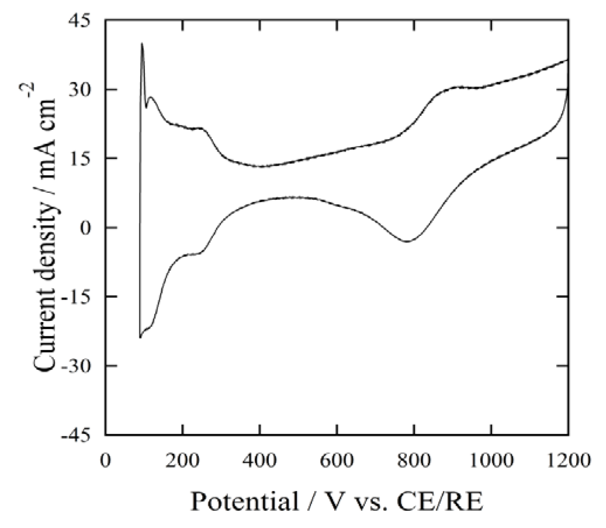
CV measurements were recorded using the MEAs produced with different I/C ratios.
Figure 7 shows a typical cyclic voltammogram of the CV measurements. All of the MEA samples gave similar features with respect to the same peak position and similar intensity in the cyclic voltammograms. The values of the electrochemical surface area (ECSA) were determined by the hydrogen adsorption charge, referred to as ΔQ
H = 0.21 mC cm
−2. All samples gave the same values of 30 m
2 g
−1 based on the ECSA. The existence of bare Pt particles without any ionomers should give lower values from the ECSA. The ionomer content was sufficient to cover all of the Pt particles when I/C = 0.14. This indicated that all of the Pt particles on the carbon nanofilaments were covered with the ionomer even at I/C = 0.14. Based on the ECSA analysis of the CV, the coverage of the Pt surface with the ionomer corresponded to the catalyst activity. The thickness of the ionomer was not related to the ECSA value. For the ratio of I/C = 0.14, the Pt surface coverage was saturated at nearly 100% and only the thickness of the ionomer increased. There was no relationship between the catalyst activity and the total ionomer amount [
11]. The thickness of the ionomer film on the Pt surface was calculated by the ionomer amount and the surface area of the carbon nanofilaments. The surface area of the carbon nanofilaments was 100 m
2 g
−1, which was measured by the BET method. The average thickness of the ionomer film was estimated to be 5.6 nm. For the ratio of I/C = 0.14, the ionomer exceeded covering of the Pt surfaces. The excess ionomer should fill the space volume. For I/C = 0.14, Pt particles on the carbon nanofilaments were covered with a thin and uniform ionomer film, suggesting a sufficient performance for the PEFC. For a ratio less than I/C = 0.14, the MEA did not maintain its solid shape.
Figure 7.
Cyclic voltammogram of the MEA: I/C = 0.46.
Figure 7.
Cyclic voltammogram of the MEA: I/C = 0.46.
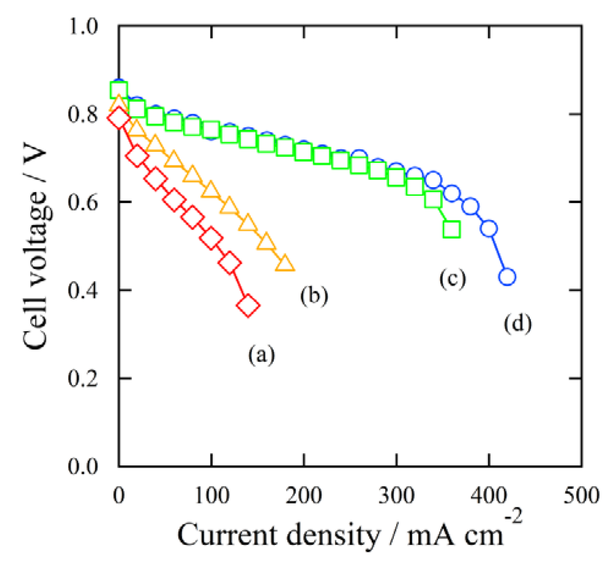
Figure 8 shows the result of the I-V measurements using the MEAs produced with different I/C ratios. The curves of
Figure 8 indicate (a): I/C = 0.69, (b): I/C = 0.46, (c): I/C = 0.23, and (d): I/C = 0.14. All of the MEAs gave similar open circuit voltage (OCV) values. For (c) and (d), with relatively lower ionomer amounts, the cell voltage gradually decreased with the current density to 350 mA cm
−2, then significantly decreased over 350 mA cm
−2. This indicated that these MEAs produced a high power density. For (a) and (b), with relatively higher ionomer amounts, the cell voltage steadily decreased with the current density even at a low current density. The MEAs of (a) and (b) could not produce a high power density.
Figure 8.
I-V measurements: MEAs were made of different ionomer ratios, (a) I/C = 0.69; (b) I/C = 0.46; (c) I/C = 0.23; (d) I/C = 0.14.
Figure 8.
I-V measurements: MEAs were made of different ionomer ratios, (a) I/C = 0.69; (b) I/C = 0.46; (c) I/C = 0.23; (d) I/C = 0.14.
The ionomer amount in the catalyst layer was confirmed to be a sufficient value at I/C = 0.14 by the CV measurement and the I-V measurements. The average thickness of the ionomer film increased with I/C ratios above 0.14. The ionomer exceeded the ratio of I/C = 0.14. The excess ionomer filled the space volume in the catalyst layer. Diffusion of reactant gases and the product water were obstructed. In the high current density range, the reaction rate is high and a large quantity of reactant needs to be supplied, and the product must be removed quickly. The diffusion of reactant gases and product water determines the overall reaction rate. The low diffusion rate should suppress the smooth reaction progress.
In general, in the PEFCs, the cell voltage decreases with increasing current density. There are three factors for the phenomenom [
12,
13]:
(I) the rate of the catalytic reaction, including charge transfer (activation overpotential);
(II) the membrane resistance, which is related to the proton conductivity (ohmic overpotential); and,
(III) diffusion performance of supplying reactant gases and removing product water (mass transport overpotential).
The cell voltage should be evaluated by these three factors in the following equation:
Where
E(I) is the cell voltage (V),
E0 is open circuit voltage (V),
R is the universal gas constant 8.3143 (J mol
−1 K
−1), T is the cell temperature (K), α is the exchange coefficient, z is number of electrons in the oxygen reduction reaction, F is the Faraday constant 96485 (C mol
−1),
I is the current density (mA cm
−2),
Rm is the membrane resistance (kΩ cm
2),
m is the mass transport coefficient (V), and
n is the growth rate factor (cm
2 mA
−1). These three factors were estimated by the experimentally measured I-V curves using the Equation (1).
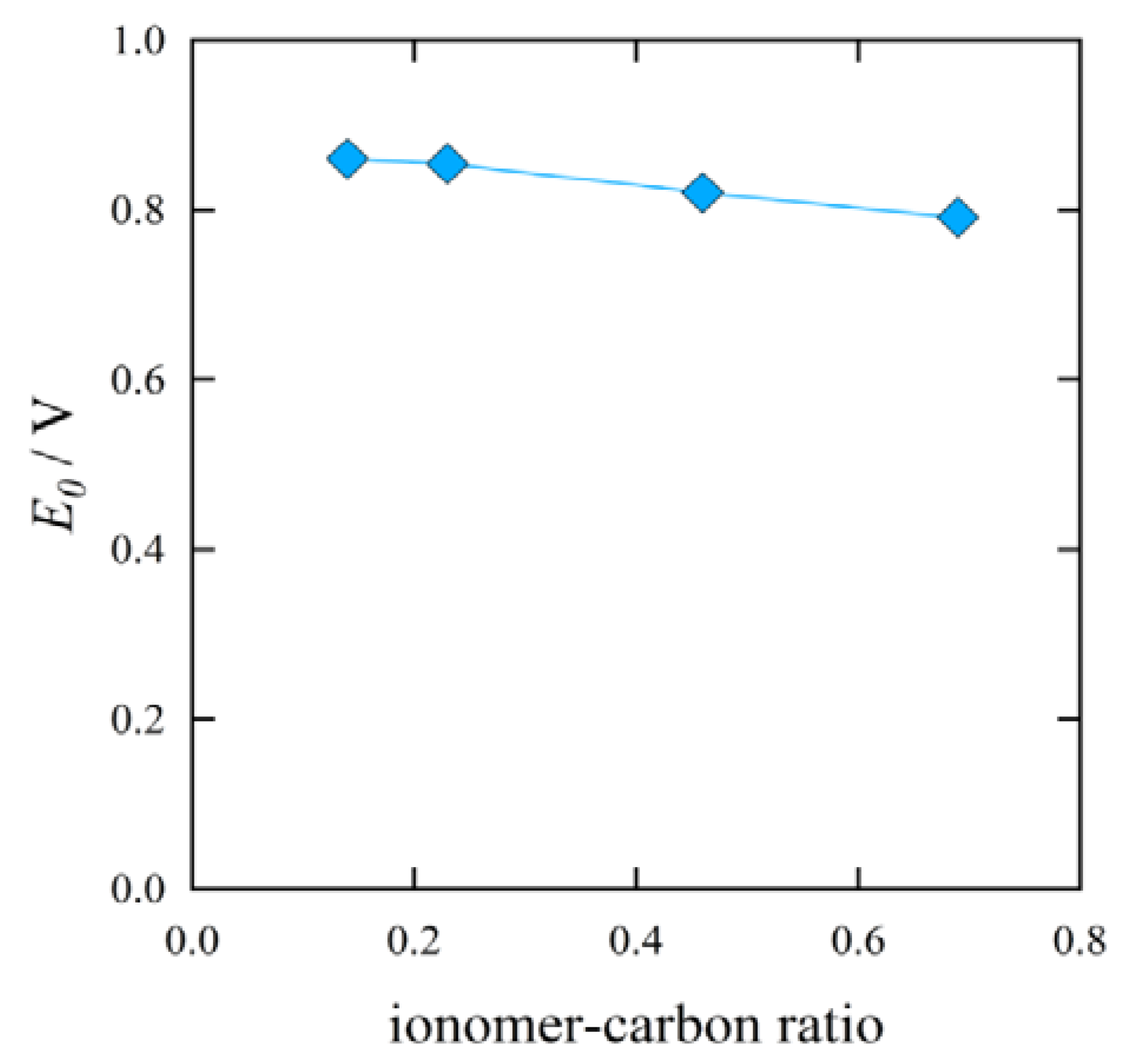
Figure 9 shows the result on the open circuit voltage
vs. the I/C ratio.
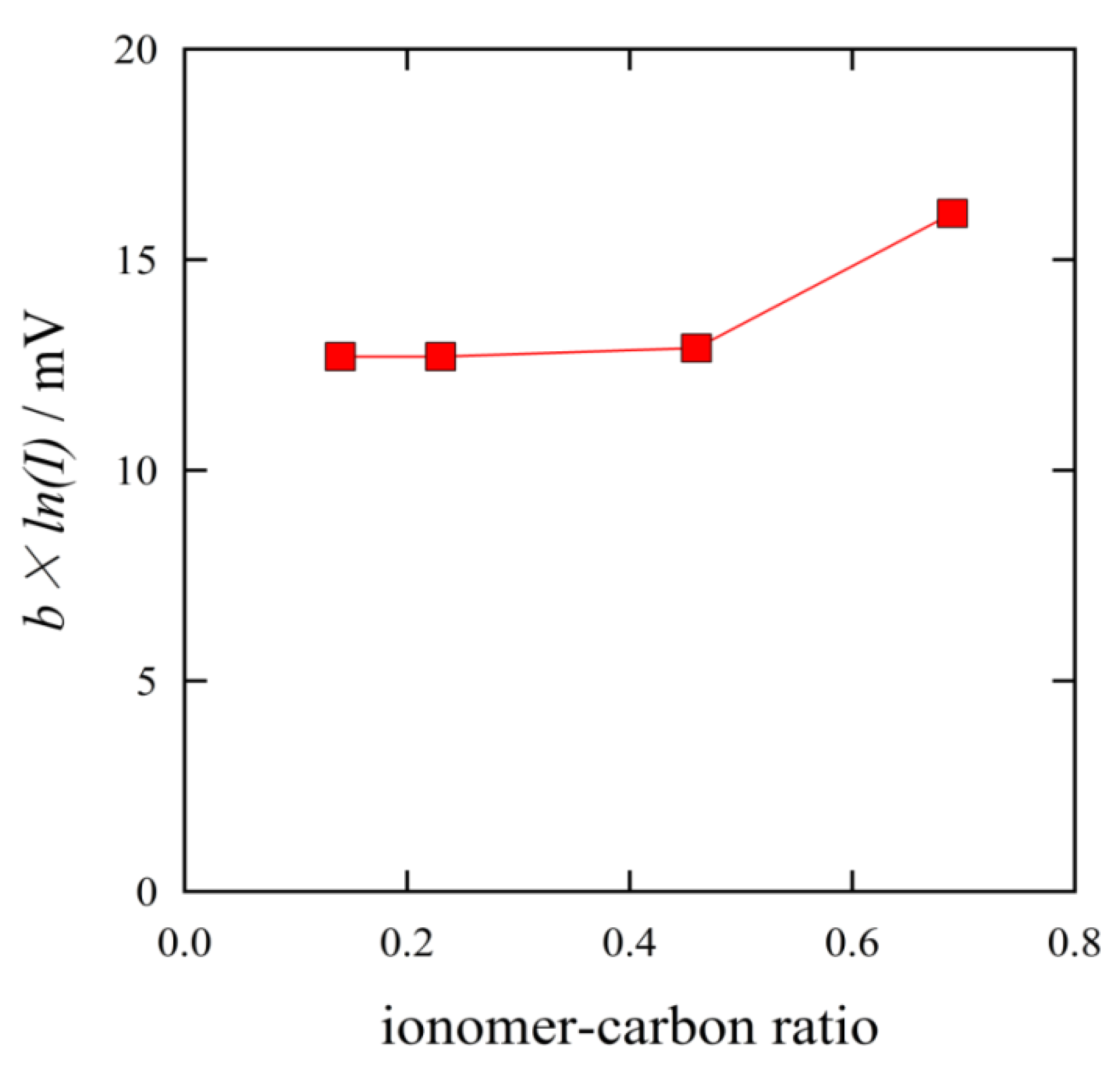
Figure 10 shows the result on the activation overpotential
vs. the I/C ratio. The values of the open circuit voltage and the activation overpotential did not vary significantly with the I/C ratio.
Figure 9.
Effect of I/C ratio on the open circuit voltage.
Figure 9.
Effect of I/C ratio on the open circuit voltage.
Figure 10.
Effect of I/C ratio on the activation overpotential.
Figure 10.
Effect of I/C ratio on the activation overpotential.
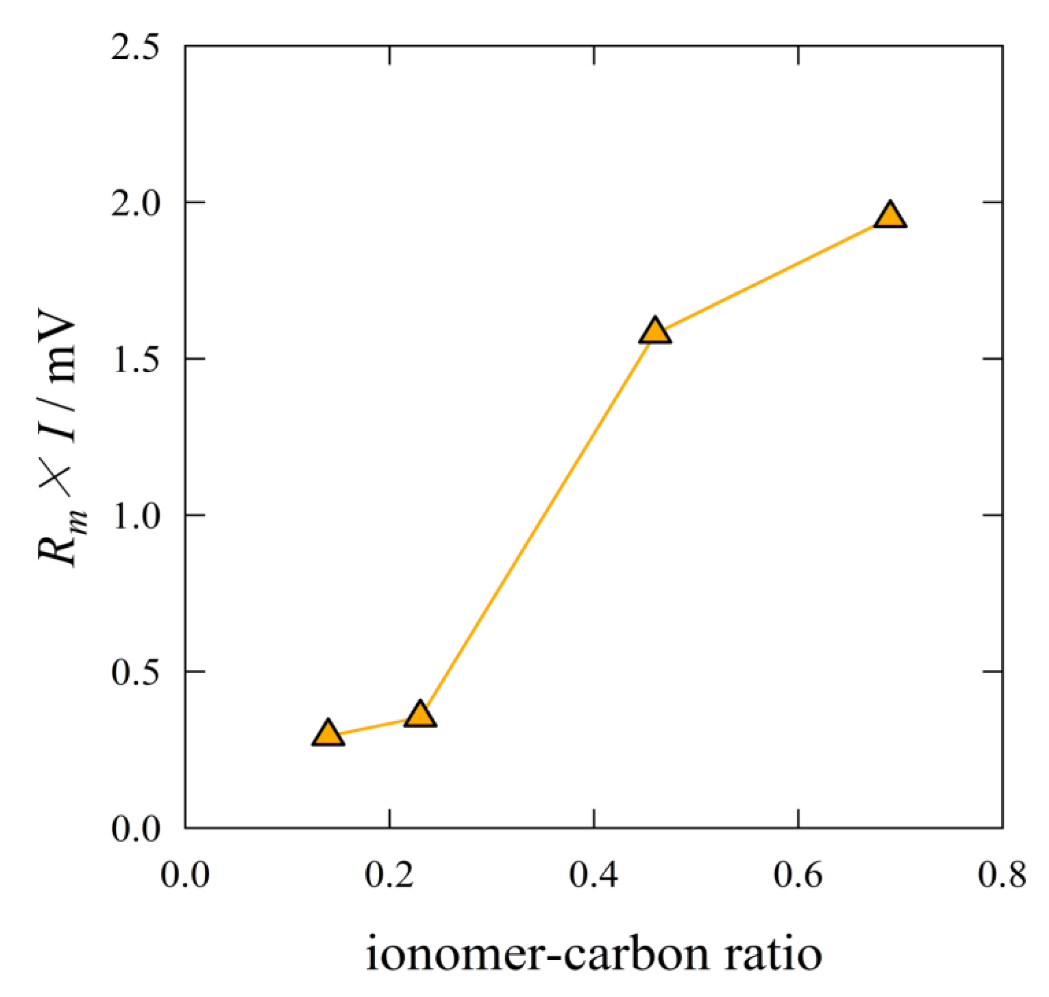
The ohmic overpotential increased with the I/C ratio, as shown in
Figure 11. The MEA with the ratio of I/C = 0.14 gave the smallest ohmic overpotential. The ohmic overpotential corresponds to the catalytic reaction rate. The reaction rate is related to the proton conduction and the diffusion of reactant gases. The smallest ohmic overpotential indicated the highest proton conduction. A thinner ionomer film provides shorter proton transfer distance. Over range of I/C = 0.23, the amount of ionomer was in excess. The excess ionomer should intercept the diffusion of reactant gases.
Figure 11.
Effect of I/C ratio on the ohmic overpotential.
Figure 11.
Effect of I/C ratio on the ohmic overpotential.
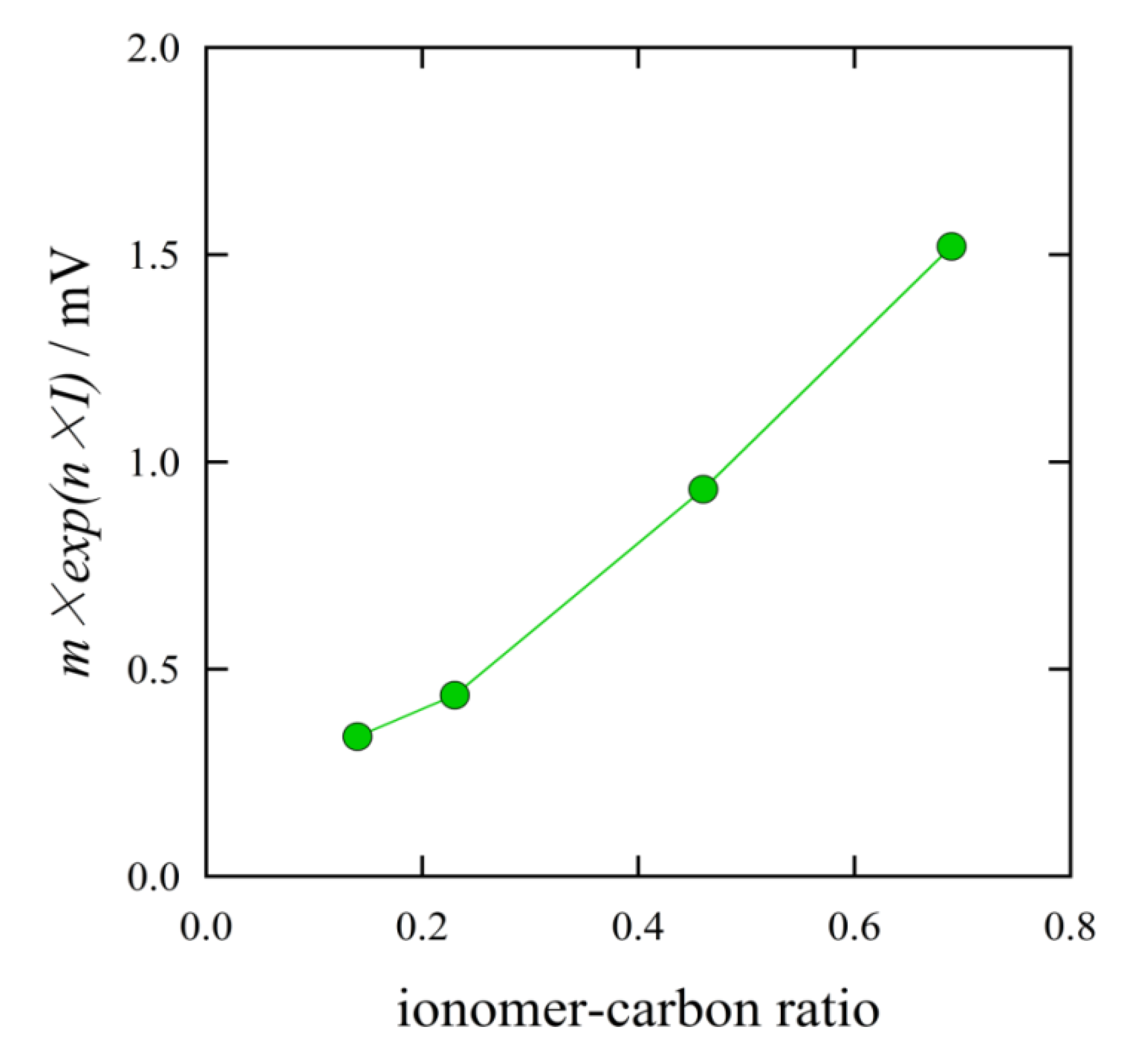
Figure 12 shows the effect on the mass transport overpotential
vs. the I/C ratio. The mass transport overpotential increased with the I/C ratio. The MEA with the ratio of I/C = 0.14 gave the smallest mass transport overpotential. This suggests that the diffusion of reactant gases and product water decreased with the increasing I/C ratio. This result was in accord with the SEM observation shown in
Figure 6. The excess ionomer filled the space volume in the catalyst layer.
Figure 12.
Effect of I/C ratio on the mass transport overpotential.
Figure 12.
Effect of I/C ratio on the mass transport overpotential.
The current density is proportional to the reaction amount per unit time. A high current density means a high reaction rate. The overall reaction rate is determined by two origins. One is the reaction rate of the reactants, and the other is the diffusion rate of the reactants and products. The reaction rate corresponds to factor I (activation overpotential, b × ln(I)). The diffusion rate corresponds to factor II (ohmic overpotential, Rm × I) and factor III (mass transport overpotential, m × exp(n × I)). The diffusion rate is determined by supplying the reactants (factors II and III) and removing the products (factor III). The I/C ratio influenced the excess ionomer; the excess ionomer caused a decreasing diffusion rate. The decrease in the diffusion rate of the reactant gases increased the ohmic overpotential (factor II) and the mass transport overpotential (factor III).
In a previous report [
1], the ratio of I/C = 0.3 yielded the best performance for the PEFC using the carbon black and Nafion system. For I/C > 0.3, very similar results were reported. However, in the case of I/C < 0.3, the ohmic overpotential increased with the decreasing I/C ratio. They reported that this indicated that the ionomer amount was not sufficient to cover all the catalyst surfaces. The ionomer network was defective, and the route of proton transfer was incomplete. In the present study, using carbon nanofilaments, the ionomer amount with the ratio of I/C = 0.14 was enough to cover the catalyst. The carbon nanofilaments used in this study had no inner pores. Carbon blacks have a lot of fine inner pores. The inner pores contribute to a very large specific surface area. However, all of the surfaces, especially the inner pore surfaces, are not effective for the reaction. Some parts of the ionomer should be consumed to fill the inner pores. The specific surface area of the carbon nanofilaments was smaller than that of the carbon blacks. All of the carbon nanofilament surfaces could effectively act as active catalytic reaction sites. The optimum I/C ratio for the carbon nanofilaments should be smaller than that for the carbon blacks. The Marimo carbon used in this study consists of fine carbon nanofilaments. There are sufficient space volumes between the carbon nanofilaments. The reactant gases and product water can easily diffuse between the carbon nanofilaments. This structure contributes to the high diffusion rate that provides a high performance for the PEFC even in the high current density range.
