Hierarchically Structured Electrospun Fibers

US Army Research Laboratory, Weapons and Materials Research Directorate, Aberdeen Proving Ground, MD 21005, USA
Polymers 2013, 5(1), 19-44; https://doi.org/10.3390/polym5010019
Submission received: 11 October 2012
/
Revised: 3 December 2012
/
Accepted: 25 December 2012
/
Published: 7 January 2013
(This article belongs to the Special Issue Electrospinning Techniques and Novel Applications of Electrospun Nanofibers)
Abstract
:Traditional electrospun nanofibers have a myriad of applications ranging from scaffolds for tissue engineering to components of biosensors and energy harvesting devices. The generally smooth one-dimensional structure of the fibers has stood as a limitation to several interesting novel applications. Control of fiber diameter, porosity and collector geometry will be briefly discussed, as will more traditional methods for controlling fiber morphology and fiber mat architecture. The remainder of the review will focus on new techniques to prepare hierarchically structured fibers. Fibers with hierarchical primary structures—including helical, buckled, and beads-on-a-string fibers, as well as fibers with secondary structures, such as nanopores, nanopillars, nanorods, and internally structured fibers and their applications—will be discussed. These new materials with helical/buckled morphology are expected to possess unique optical and mechanical properties with possible applications for negative refractive index materials, highly stretchable/high-tensile-strength materials, and components in microelectromechanical devices. Core-shell type fibers enable a much wider variety of materials to be electrospun and are expected to be widely applied in the sensing, drug delivery/controlled release fields, and in the encapsulation of live cells for biological applications. Materials with a hierarchical secondary structure are expected to provide new superhydrophobic and self-cleaning materials.
1. Introduction
Self-assembled nanostructures are gaining attention in the fields of tissue engineering, drug delivery, sensing, catalysis and energy harvesting/storage [1,2,3,4,5,6,7,8]. In particular, nanofiber materials are of great interest because of their long length scales, resulting in very high aspect ratios, and the high degree of fiber orientation possible. Nanofibers are generally prepared using drawing with a micropipette, template synthesis, phase separation, chemical vapor deposition, melt blowing, and electrospinning [9,10,11]. Of the aforementioned techniques, electrospinning is the most versatile and simplest method of preparing such nanofibers. It is also potentially scalable and requires little equipment. Electrospinning is an electrostatically-driven process that generates fibers of nanometer to micrometer diameters. Specifically, when a high voltage is applied to a liquid droplet, electrostatic repulsion overcomes surface tension to stretch the droplet. If molecular cohesion or chain entanglement in the droplet is sufficiently high, the droplet does not break-up (electrospray), but instead continues to stretch to form fine fibers on a grounded collection target. During the electrospinning process, the jet undergoes a whipping instability, which is the primary mechanism for the formation of sub-micron fibers [12,13].
Collector geometry can influence mat morphology, such as fiber alignment and pattern. Collectors can be stationary, such as metal plates or parallel electrodes, or rotating-type disks or mandrels [14]. In general, a randomly oriented web of fibers is collected on static targets, whereas aligned fibers are collected on spinning substrates. Some collectors possess unique geometries to affect particular fiber orientation or patterns. Theron et al. used a knife-edge collector to generate highly aligned fibers, whereas others have used collectors with grids or charged needles to create patterned nanofibrous mats [15,16,17,18,19]. Several researchers have used a series of parallel electrodes to generate aligned fibers rather than rotating collectors [20,21,22,23]. Li et al. used a pattern of four electrodes to generate a cross-bar array of aligned nanofibers [24].
Polymers in the solution and melt form, as well as non-polymeric materials such as ceramics and metals, can be fabricated into nanofibers via electrospinning. An assortment of natural polymers, such as the proteins collagen, elastin and silk fibroin, has been electrospun [25,26,27,28,29,30,31]. In addition, a wide variety of synthetic polymers such as polystyrene (PS), polycaprolactone (PCL), poly(methyl methacrylate) (PMMA) and poly(vinyl alcohol) (PVA) have been electrospun from solution. Melt electrospinning requires that a heating system surround the reservoir and, despite its advantages of improved cost effectiveness and environmental safety due to the absence of solvents in the process, is generally more challenging. Polyethylene and polypropylene are two polymers that have been successfully fabricated from the melt [32,33]. Ceramic fibers such as TiO2 have been fabricated from a sol of ceramic precursor and a host polymer such as polyvinylpyrrolidone (PVP) [34]. Metallic fibers such as copper fibers have also been generated by electrospinning a metal acetate or nitrate solution with a host polymer, followed by degradation of the host polymer and reduction [35].
The electrospinning field is extremely broad, and consequently there have been many useful reviews discussing various aspects from detailed fiber formation mechanisms to the formation of nanocomposite fibers to discussions on the wide range of applications [24,36,37,38,39]. On the other hand, the focus of this review is quite narrow, highlighting unique fiber morphologies. The review will briefly cover the factors impacting the morphological characteristics of nanofibers such as fiber diameter and porosity, patterning, and then focus on primary and secondary hierarchical structures of electrospun nanofibers.
2. Gross Morphology
2.1. Fiber Diameter
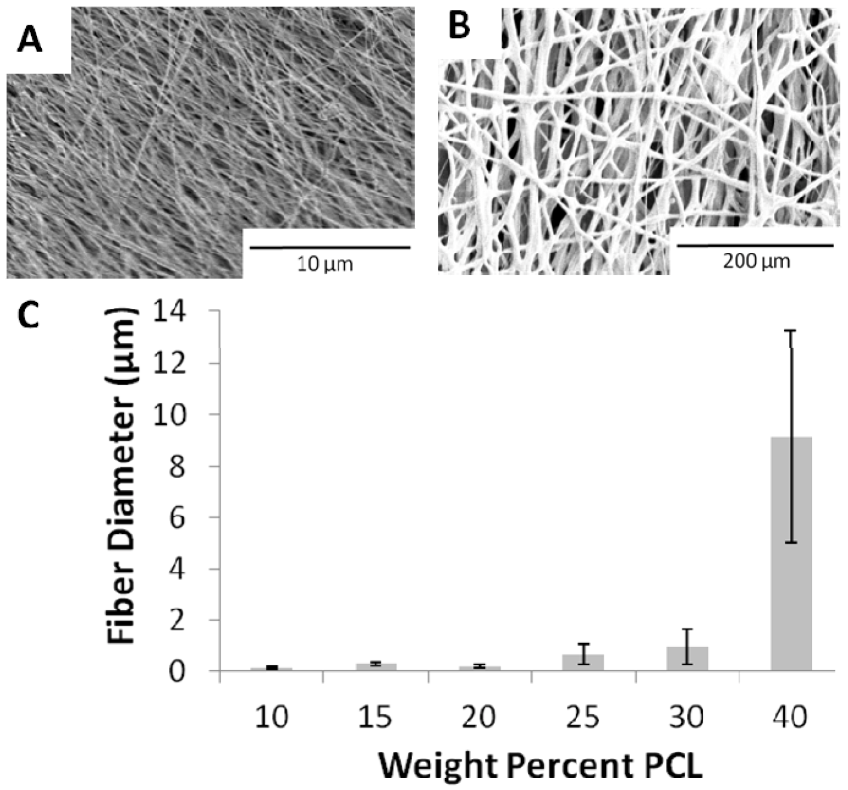
One of the most highly studied and fundamental areas in electrospinning is control over fiber diameter. Many factors that affect the fiber diameter, including solution concentration, viscosity, molecular weight, polymer feed rate, capillary size, solution conductivity, working distance and applied voltage [11,40]. Shin et al. found that the resulting fiber diameter was highly dependent on the stretching and acceleration of the fiber jet prior to solidification [41]. Fridrikh et al. developed a model to predict fiber diameter based on surface tension and electrostatic charge repulsion. In this model, solution conductivity and viscosity are also taken into account [42]. Of the many parameters discussed, concentration/solution viscosity is one of the most important factors affecting fiber diameter. Demir et al. found that fiber diameter of polyurethane fibers was proportional to the cube of the polymer concentration, following a power law relationship [43]. Figure 1 displays the effect of polymer concentration on the fiber diameter of PCL fibers prepared from dimethylformamide (DMF) and methylene chloride. As can be clearly seen from the images and chart, the fiber diameter increases significantly from 10–20 wt % PCL to 40 wt % PCL.
Figure 1.
Scanning electron micrographs of electrospun polycaprolactone (PCL) fibers formed from solutions of varying PCL concentrations in methylene chloride and dimethylformamide (DMF) (50/50 w/w) solvent. (A) 20 wt % PCL; (B) 40 wt % PCL; (C) chart of PCL concentration (wt %) and fiber diameter. Data are expressed as mean ± standard deviation.
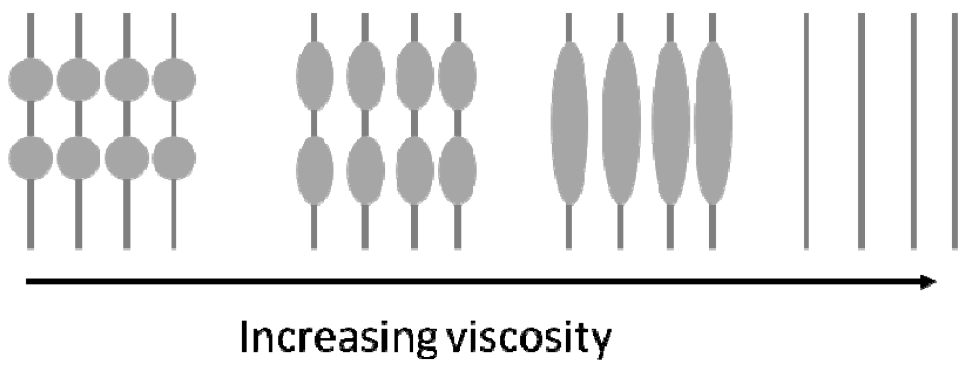
The extent of polymer chain entanglements, expressed as solution viscosity, plays a critical role in controlling not only the fiber diameter, but also the fiber quality or uniformity. If the density of chain entanglements is less than some critical value (as defined by each polymeric system), the electrospinning jet breaks up, and beads or electrosprayed droplets rather than fibers are formed. If the density of entanglements is sufficient but the extent of chain overlap is less than the critical value, beaded fibers are formed [44,45,46]. Interestingly, the morphology of the beads on the fibers changes shape as the solution viscosity changes from a rounded droplet-like shape with low viscosity solutions to stretched droplet or ellipse to smooth fibers when sufficient viscosity is achieved, as shown in Figure 2 [47,48,49]. Zong et al. found that not only does the shape of the beads change with viscosity, but the spacing between the beads increases. The researchers postulated that the drying of the fibers had a large effect on resulting fiber morphology. Wet fibers, formed from lower concentration solutions, undergo a solidification process governed by surface tension and a relaxation process controlled by the viscoelastic property. In contrast, fibers formed from higher concentrations are generally dried by the time they are collected [50].
Figure 2.
Schematic showing the effect of increasing the polymer solution viscosity on the morphology of the resulting electrospun fibers.
Figure 2.
Schematic showing the effect of increasing the polymer solution viscosity on the morphology of the resulting electrospun fibers.

2.2. Porosity
Fiber mat porosity is another controllable parameter that has been extensively studied, in particular for tissue engineering (cellular infiltration) and filtration applications. There are many approaches to controlling the pore size in nanofiber mats including the addition of salt particles or ice crystals to the electrospinning solution, the formation of composites made of electrospun fibers and electrosprayed polymer beads that can be later removed, or the generation of micron-sized fiber diameter scaffolds [51,52,53,54,55,56]. The latter approach generates micron-sized inter-fiber spaces because pore size, in general, scales with fiber diameter. As a possible compromise to maintain the nanometer-diameter fibers and high surface area and micrometer-diameter fibers for sufficient pore-size for air/fluid diffusion, some researchers have explored forming composites of nanometer and micrometer fibers [57,58], electrospinning nanometer fibers onto micrometer fibers [59], and electrospinning nanometer fibers of two polymers, and then later removing the fibers from one of the polymers to increase the porosity [60].
2.3. Patterns
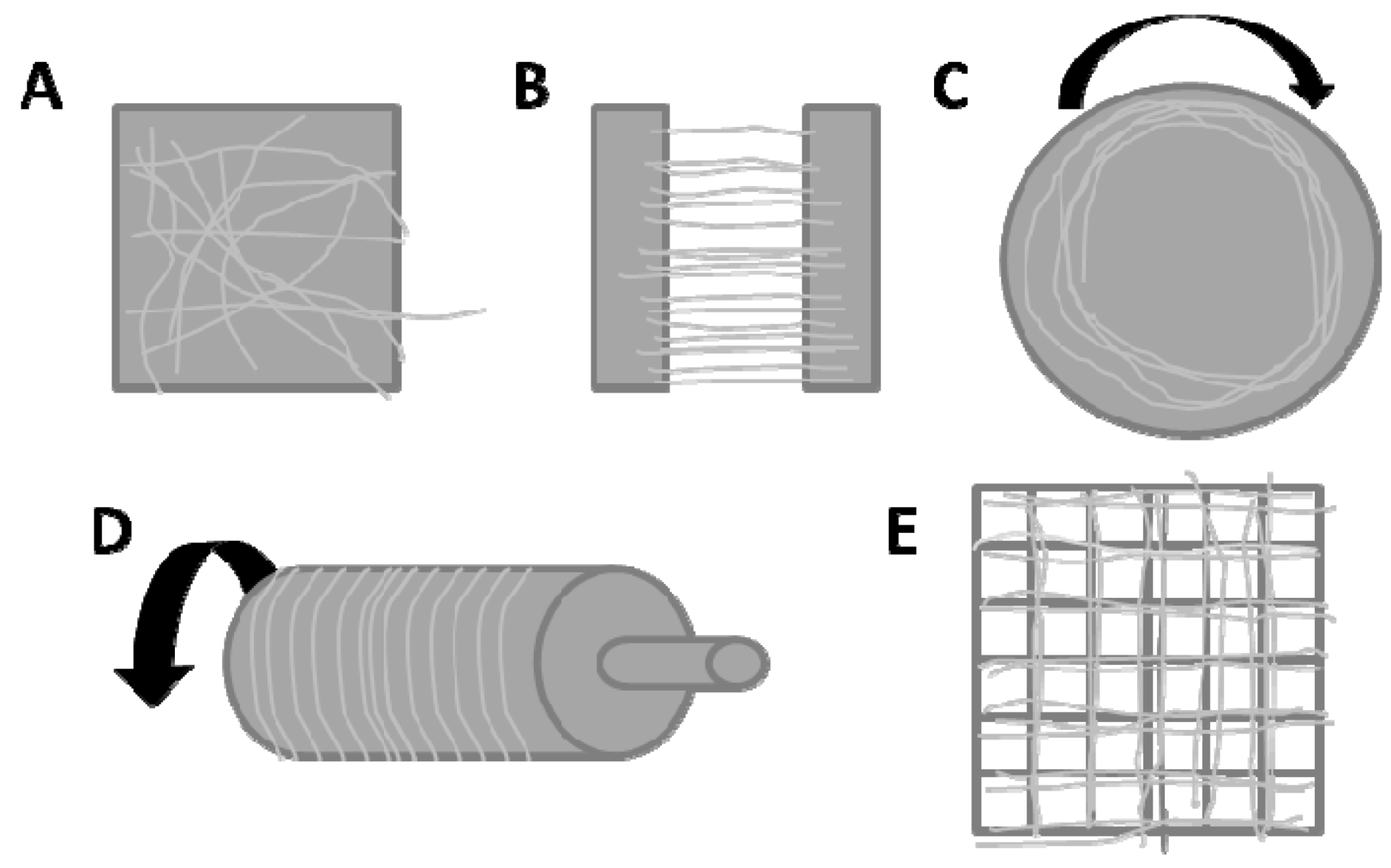
Patterning is another way to control the morphology/architecture of the electrospun fiber mat. The effect of collector geometry, particularly for the alignment of fibers, has been extensively studied [15,24,61,62,63]. Rotating collectors such as mandrels or disks, as well as electrodes separated by a gap, are facile ways to generate oriented fibers [64]. Unaligned or randomly oriented fibers are traditionally collected on a static substrate, such as a grounded metal plate. To generate micro- or macro-scale patterns of nanofibers, researchers have explored the use of conductive grids or a series of charged needles to guide the collection of fibers along the charged regions [17,18,19,65]. Li et al. developed a variety of aligned cross-bar patterns using a layer-by-layer approach with series of conductive grids with void gaps [66]. Zussman et al. attached an aluminum table to a rotating disk collector to generate cross-bar patterns in a one-step process [67]. Some researchers have developed collectors to generate patterns of fibers that mimic the natural fibrous patterns seen, for example, on bamboo leaves or goose feathers [68]. Figure 3 shows a variety of collectors and their effect on the nanofiber mat pattern. Ding et al. recently demonstrated the selective deposition of nanofibers on an elastomeric substrate containing gold-coated pyramidal spikes [69]. Star and radial fiber patterns have also been prepared using enamel patterned steel-sheet collectors [70]. Ye et al. developed a method to create a bird’s nest pattern of fibers using an unpatterned plate collector. To do this, they doped chlorinated polystyrene (PS) and polypropylene with an ionic liquid that enhanced the charge accumulation of the collecting fibers. Thus, the fibers were able to form only thin layers of fibers aligned on top of one another before depositing in another location on the collector, which eventually created a nest-like pattern. The use of an insulating collector enhanced the pattern formation by increasing the charge accumulation at the collector [71].
Figure 3.
Different collector geometries for electrospinning. (A) static plate; (B) parallel electrodes; (C) rotating disk; (D) rotating mandrel; (E) grid.
Figure 3.
Different collector geometries for electrospinning. (A) static plate; (B) parallel electrodes; (C) rotating disk; (D) rotating mandrel; (E) grid.

Another method used to generate patterned fiber mats is the controlled deposition of fiber using direct-write methods, sometimes referred to as Near Field Electrospinning (NFES) or Scanned Tip Electrospinning Deposition (STED) [72,73,74,75,76]. This process generally uses conductive tips rather than needles with extremely small tip-sample separations [8,77]. At such small working distances, the fibers do not undergo the bending instability and therefore are collected in a more stable region of the jet, allowing for highly controlled fiber collection, generally on a moving substrate. The benefit of this technique is that micro-meter-sized patterns can be generated within the resolution limits of the linear motion stage utilized for collection. Kameoka et al. was able to use the STED method to deposit aligned nanoparticles in a polymeric fiber [76].
Other methods to generate micro-scale patterns include magnetic electrospinning with magnetic nanoparticles doped into the fibers and subsequently aligned in a magnetic field, micro-contact transfer of fiber patterns using a patterned elastomeric stamp, and photolithography [78,79,80,81]. Carlberg et al. incorporated the photoinitiator benzoin methyl ether into a polyurethane solution, formed fibers and then exposed the fiber mat to ultraviolet light using a mask to create patterns [80]. Sharma et al. used a similar procedure with electrospun fibers composed of a photoresist to generate micro-sized patterns of carbon nanofibers after post-processing steps [81].
3. Hierarchical Primary Structures
3.1. Introduction
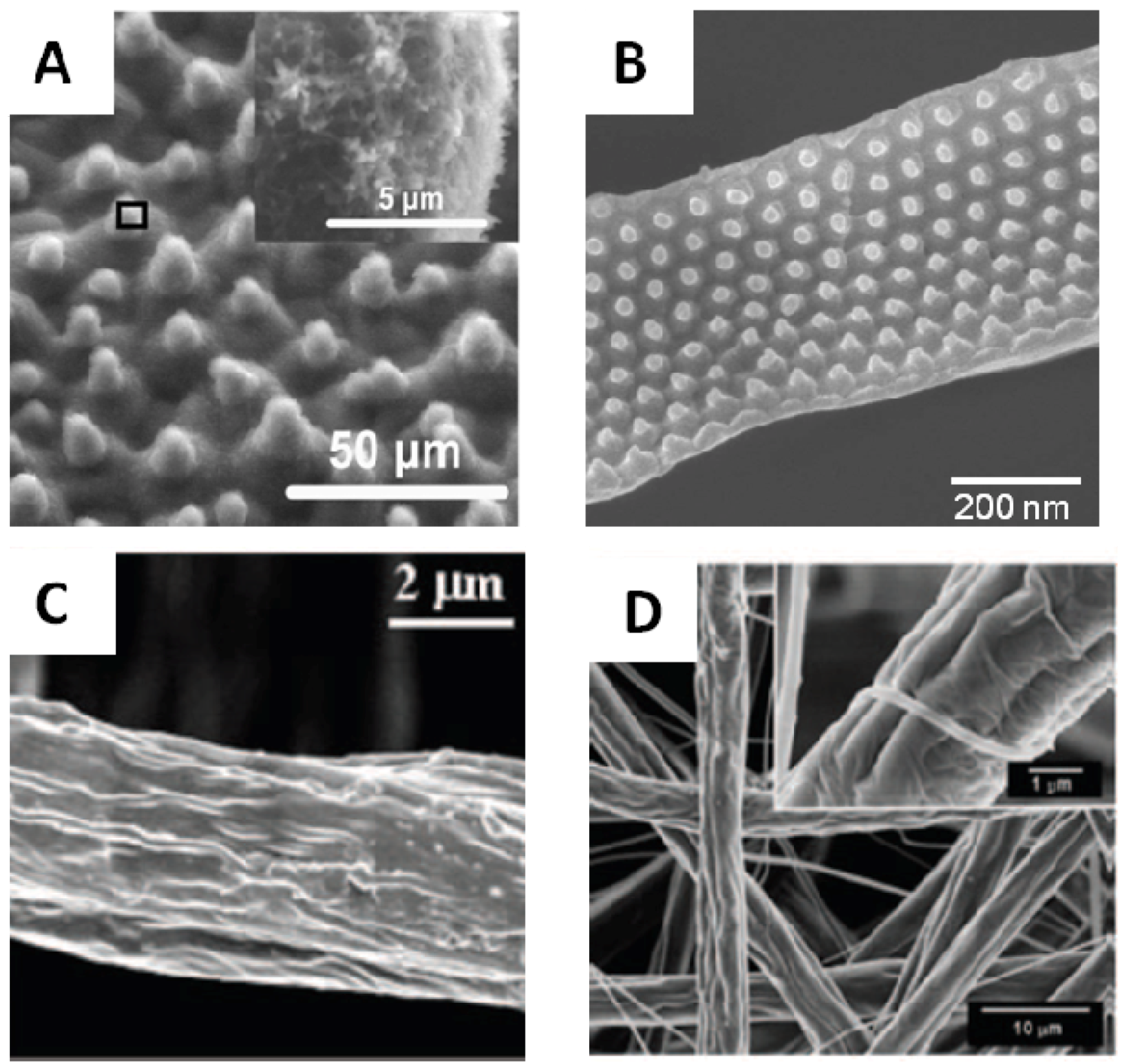
In addition to the well-studied gross morphology of electrospun fibers, such as fiber diameter, porosity, and the newer area of micro- to macro-scale patterns, electrospun materials exhibit various other fascinating morphologies, such as helical, ribbon-like, beads-on-a-string, multi-channel tubular, porous honeycomb, nanoporous, nanopillared, core-shell and hollow structures, many of which are also observed in nature [82,83,84,85,86]. Much of the focus in generating nanofibers with hierarchical structures is to impart new properties to the materials, such as superhydrophobicity, self-cleaning, or unique optical properties. Figure 4 displays various natural hierarchical structures side-by-side with bio-mimetic versions created from electrospun fibers. These particular bio-mimetic fibers possess the unique property of superhydrophobicity, as observed in the natural lotus and silver ragwort leaves.
Figure 4.
Examples of electrospun bio-mimics of natural hierarchical structures. (A) Lotus leaf; (B) pillared poly(methyl methacrylate) (PMMA) electrospun fiber mimic; (C) silver ragwort leaf; (D) electrospun fiber mimic made from nylon 6 and polystyrene (PS). (Figure (A) reprinted with permission from Wang et al. [87]. Copyright 2009 American Chemical Society; Figure (B) reprinted with permission from Chen et al. [88]. Copyright 2012 American Chemical Society; Figure (C) reprinted with permission from Miyauchi et al. [89].Copyright 2006 IOP Science; Figure (D) reprinted with permission from Li et al. [90]. Copyright 2009 American Chemical Society).
3.2. Internally Structured Fibers
3.2.1. Core Shell Fibers
Core-shell fibers typically are bi-component fibers consisting of a core of one material type and an encapsulating shell of another material. These types of fibers can be very useful in the drug-delivery or tissue engineering fields by allowing the controlled release of a drug or growth factors [91,92,93,94]. In addition, a structurally supportive but non-biocompatible core can be encapsulated with a biocompatible sheath [95,96]. Non-electrospinnable materials, such as low molecular weight or conjugated polymers with limited solubility, can be fabricated into fibers via formation as the fiber core and subsequent removal of the shell [24,97,98,99,100]. Core-shell fibers are traditionally made by electrospinning of the core material, which serves as a template for the deposition of the shell layer via chemical vapor, plasma or solution deposition, or through use of a co-annular needle [101,102,103].
Core-shell fibers, particularly with the core removed to make hollow tubes, also have many applications in the sensing field. Choi et al. generated hollow ZnO fiber sensors by coating a sacrificial electrospun fiber template with ZnO followed by calcination. The hollow ZnO fiber membrane showed enhanced sensitivity for NO2 compared to a ZnO thin film [104]. Gao et al. prepared polyaniline tubes using electrospun PVA as a template. The nanotubes showed a higher selectivity and quicker response to trimethylamine gas [105]. Park et al. made TiO2-ZnO core-shell fibers using a TiO2 template and atomic layer deposition. The core-shell fibers showed good oxygen sensing capability [106]. Zhan et al. generated hollow TiO2 fibers using a coaxial spinneret and machine oil as the core fluid. By adjusting the sol and oil pressures, tunable wall thicknesses and inner diameters were achieved [107].
As mentioned above, core-shell fibers have many applications in the biological fields. Zhang et al. prepared core-shell PCL-collagen fibers using a co-annular needle. The growth of human dermal fibroblasts on core-shell fibers was compared to PCL fibers soaked in collagen. Cellular proliferation was improved up to 200% on the core-shell fibers compared to the surface treated fibers [96]. Zhang et al. encapsulated the model protein fluorescein isothiocyanate-conjugated bovine serum albumin (FITC-BSA) within a polyethylene glycol core and PCL shell. Variation of the inner and outer flow rates controlled the loading of FITC-BSA and fiber diameter, respectively [108]. Townsend-Nicholson et al. used a coaxial spinneret to encapsulate living mammalian cells in polydimethylsiloxane fibers. The post-cultured cells were viable and showed no evidence of evidence cellular damage from the electrospinning process [109]. Klein et al. encapsulated three different strains of bacteria into polyethylene oxide (PEO)/PCL core-shell fibers for bioremediation applications. The encapsulated cells maintained some of their phosphatase, β-galactosidase and denitrification activity [110].
Recently, superhydrophobic core-shell fibers have been fabricated. Han et al. used coaxial electrospinning to generate superhydrophobic and oleophobic fibers for the first time. The electrospinning of normally non-electrospinnable Teflon was facilitated with a PCL core using a co-annular needle set-up. Water contact angles of 158° and dodecane contact angles of 130° were reported [111].
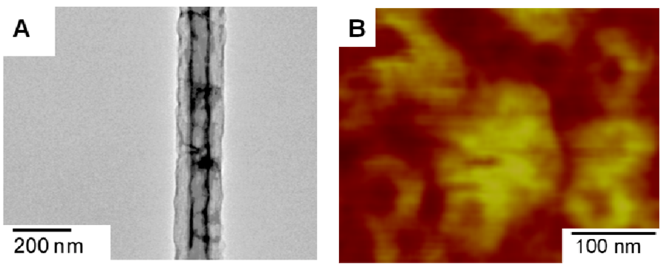
There are several drawbacks using the main two methods, template deposition and a co-annular needle, to form core-shell fibers. The former requires two or more steps and may result in a non-uniform shell coating. The latter method has parameters that must be carefully considered, including solution viscosity, miscibility, and interfacial tension requirements between the two solutions to obtain continuous entrainment of the core material within the shell [95]. Recently, core-shell fibers have also been fabricated by electrospinning certain emulsions, a process that avoids many of the drawbacks associated with the co-annular approach [112,113,114]. Figure 5 displays a schematic of a co-annular needle as well as a single-nozzle emulsion electrospinning set-up and the formation of core-shell fibers. Figure 6 displays a transmission electron microscopy (TEM) image of a core-shell fiber formed from a polyacrylonitrile (PAN) and PMMA emulsion solution and the corresponding fiber cross-section imaged using atomic force microscopy (AFM).
Figure 5.
(A) Schematic of co-annular needle set-up to generate core-shell electrospun fibers; (B) single-nozzle set-up to generate core-shell fibers from an emulsion solution. Insets show a detailed schematic of the core-shell jet.
Figure 5.
(A) Schematic of co-annular needle set-up to generate core-shell electrospun fibers; (B) single-nozzle set-up to generate core-shell fibers from an emulsion solution. Insets show a detailed schematic of the core-shell jet.
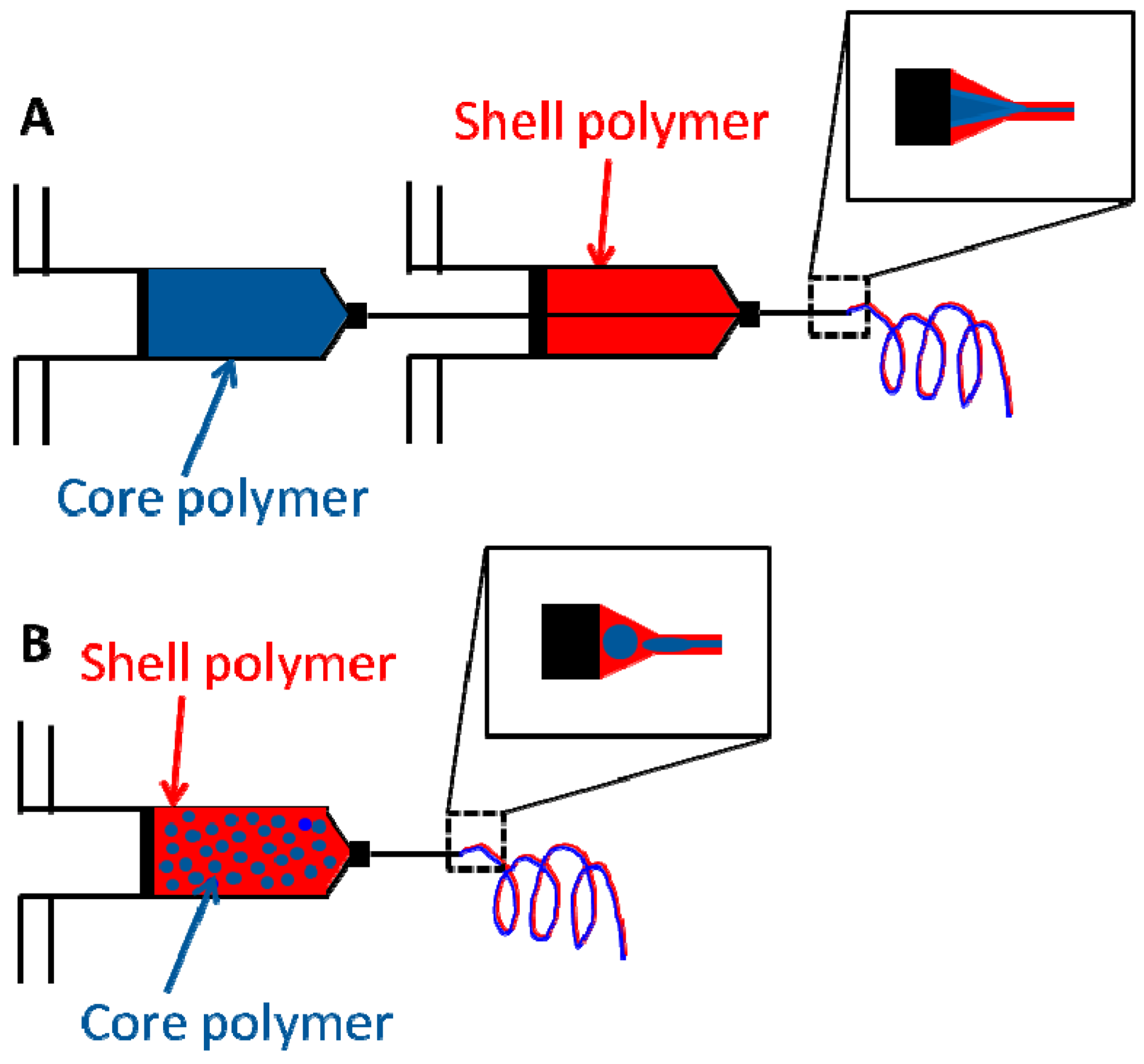
Figure 6.
Core-shell PMMA-PAN electrospun nanofibers prepared from an emulsion solution. (A) TEM image of core-shell fibers; (B) AFM phase image of core-shell fiber cross-section. (Reprinted with permission from Zander et al. [114]. Copyright 2011 American Chemical Society).
Figure 6.
Core-shell PMMA-PAN electrospun nanofibers prepared from an emulsion solution. (A) TEM image of core-shell fibers; (B) AFM phase image of core-shell fiber cross-section. (Reprinted with permission from Zander et al. [114]. Copyright 2011 American Chemical Society).

Hollow fibers can be formed by removing the core material via heating or solvent extraction. Sanders et al. used a two solvent single-nozzle electrospinning method to encapsulate the protein bovine serum albumin in poly(ethylene co-vinyl acetate) (EVA) fibers. Rather than a continuous core-shell structure as generated by certain emulsion solutions, the fibers contained microencapsulated aqueous domains containing the protein in the surrounding EVA fibers [115]. A wide variety of core-shell fibers have been generated, including PCL/gelatin, the conjugated polymer polyhexylthiophene with a polypyrrolidone sheath, fibers with various encapsulated live cells, and hollow ceramic fibers using oil as the core [98,102,103,116,117].
3.2.2. Fibers Formed from Block Copolymers
Block copolymers are known to self-assemble into a variety of nanoscale morphologies including spheres, rods, micelles, lamella and cylinders [118]. Block copolymers are generally studied in the bulk or in thin films, but recently there have been some studies of block copolymers in electrospun fibers. The same domains as in the bulk have been observed, but they are generally not as well ordered or as regular in shape due to the fast solvent evaporation and mechanical deformation during the electrospinning process [118,119]. Ruotsalainen et al. observed lamellar-within-spherical structures for a poly(styrene-b-vinylpyridine) system [119]. Rutledge et al. prepared electrospun block copolymers using a co-annular needle system, with the copolymer confined within a shell with a high glass transition temperature [120,121]. The shell served as a process aid for the core material during electrospinning, poly(styrene-b-isoprene-b-styrene), and also confined the copolymer during the subsequent annealing step [120]. Gyroid-type structures were formed when the block copolymer poly(styrene-b-dimethyl siloxane) was used with a poly(methacrylic acid) shell [121]. Ma et al. reported the formation of superhydrophobic fibers by the electrospinning poly(styrene-b-dimethylsiloxane). The water contact angle of 163° was attributed to the combined effect of surface enrichment of siloxane and increased surface roughness of the nanometer diameter fibers [122]. These internally structured polymers have a wide variety of applications from advanced filters, optical materials, and templates for nanoscale objects and to direct nanoparticle assembly [120,123].
3.3. Helical
Inspired by the structure of proteins and DNA, nanofibers with nano- and micro-scale helical structures exhibit some unique properties, such as higher porosity, elasticity, and toughness, which make them good candidates for surgical fibers, textiles, filters, and components in microelectromechanical systems (MEMs). Helical nanofibers made from conjugated polymers have unique electronic and optical properties. They are expected to be used as building blocks in novel organic nanophotonic and electronic devices, as well as field-effect transistors, energy storage units and sensors [124,125,126,127,128]. Nanoscale helices have been made from the contraction of a manganese oxide sol gel upon solvent evaporation, as well as from zinc oxide and silicon dioxide using vapor processing methods [129,130,131]. Recently, researchers have found that electrospinning is an efficient and facile method to fabricate such helical nanofibers. Usually, two polymers with different properties, such as conductivity or elasticity, are electrospun, either as a blend or as a core-shell or side-by-side system, to generate bi-component fibers. Some examples of these type of bicomponent fibers are poly(p-phenylene vinylene) (PPV)/PVP fibers or PEO and the conductive polymer poly(aniline sulfonic acid). The authors suggest that the helical micro-coils observed were formed spontaneously upon contact with a conducting substrate due to the viscoelastic contraction of the fiber upon partial charge neutralization [132,133]. Lin et al. developed a microfluidic electrospinning nozzle for the side-by-side deposition of two polymers to make a bi-component fiber [134]. Bi-component fibers with helical morphology were fabricated using this nozzle with equal flow rates from an elastomeric (polyurethane) and thermoplastic (polyacrylonitrile) polymer solution. Adjusting the flow rate of the two polymer solutions influenced the fiber morphology. Higher flow rates of the thermoplastic polymer reduced the helical nature of the resulting fibers, whereas increased flow rates for the polyurethane resulted in curly and beaded fibers. Chen et al. electrospun core-shell fibers of a thermoplastic polyurethane and the stiff polymer Nomex®, and observed helices with the addition of LiCl to increase the solution conductivity [135]. The relative amount of the stiff polymer in the core was varied, and the most homogenous nanosprings were formed when the relative ratio of the core and shell polymers was near 50:50.
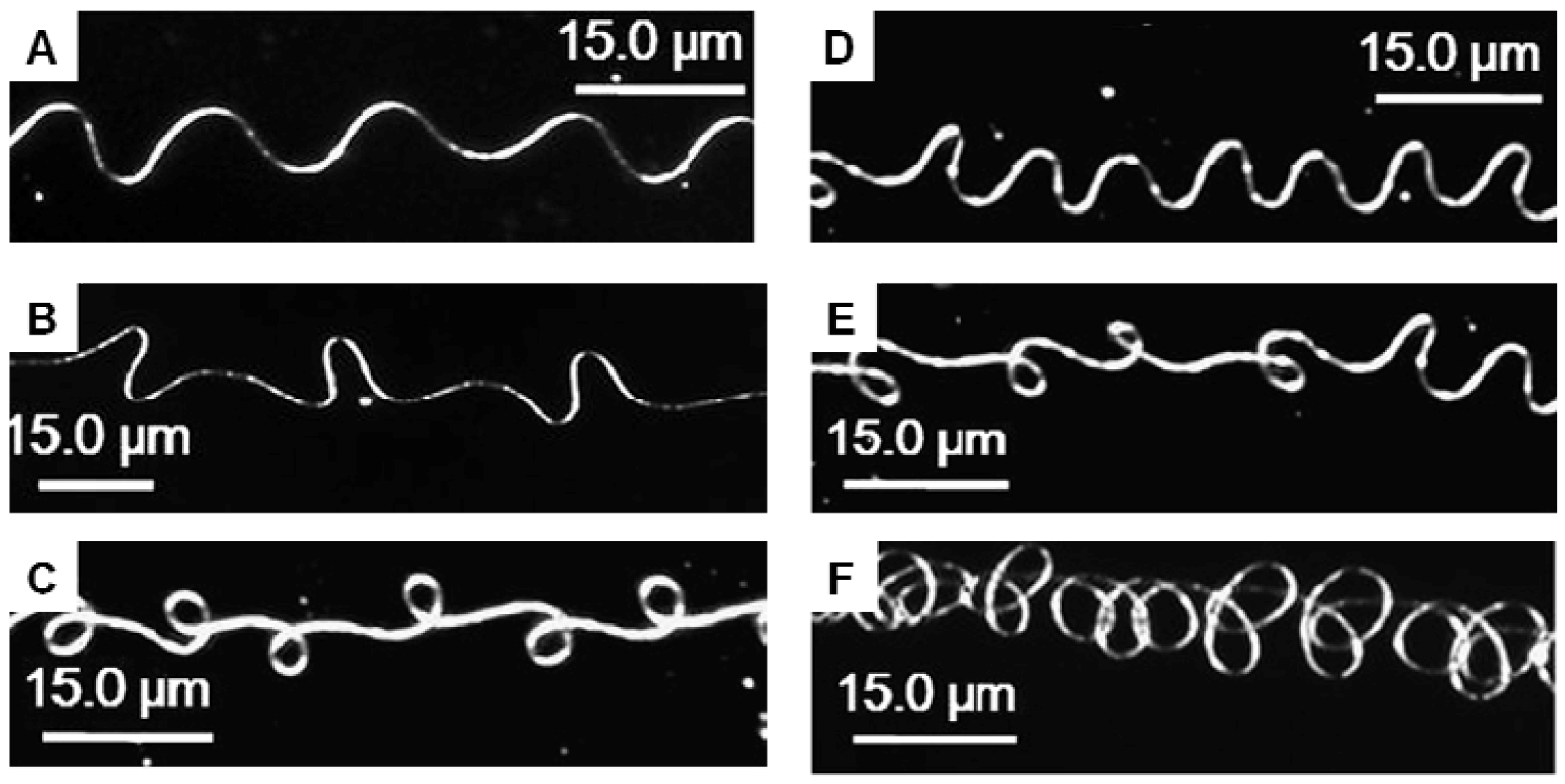
Other researchers have shown the formation of helical nanofibers from a pure single-component fiber. Shin et al. reported the formation of helices from poly(2-acrylamido-2-methyl-1-propanesulfonic acid) dissolved in a mixture of water and ethanol [136]. The helical fibers were able to be linearly oriented when collected on parallel electrodes. In the aforementioned work, the formation of helical structures was more heavily influenced by the physical forces caused by the bending instability of the jet compared to the effects of electrical charge or difference in polymer elastic modulus and differential shrinkage [134]. Canejo et al. observed the spontaneous twisting of cellulose fibers in the liquid crystalline phase. They attributed the helical formation to the native chirality of the polymer and the high solution concentration used in the study [137]. Several researchers have focused on using a Near Field Electrospinning approach in which the helical patterns are formed in the region before the jet experiences electrical instability. According to the Han et al. model, the straight electrospinning jet spontaneously forms a coil in response to the positive changes carried by the jet upon impingement on the collector [138]. A combination of solution concentration, voltage and frequency of the applied voltage (e.g., sinusoidal) varies the pitch length and radii of the coils. A wide variety of buckling/coiled patterns, including sinusoidal trajectories, coiled structures, and figure-of-eights, can be achieved. Figure 7 displays a selection of coiled fiber patterns generated using the electrospinning approach. Using this technique, researchers have fabricated PS, PEO, polylactic acid (PLLA) and nylon fibers with helical morphology [138]. In many cases, the addition of salt to the polymer solution increased the conductivity of the solution, although the exact mechanism of how this increases coil formation remains unknown [135,139]. Both stationary collectors, such as water, and laterally moving collectors have been used to collect coiled fibers, with slower collector speeds generating more uniform coils [140,141].
Yu et al. fabricated helical PCL fibers, and controlled the coil size based on solution concentration. A tilted glass slide was used as the collector and it was found that tilt angles greater than 45° did not result in helical fibers [142]. Helical light-emitting conjugated polymers in which the polymer molecular weight affects the loop size and corresponding color shift have also been fabricated using the electrospinning technique [143]. The fibers with the most stretched helical geometries were formed from polymer solutions with the highest molecular weights. Xin et al. electrospun PPV blended with PEO. By varying the PEO composition, the range of fluorescence could be tuned from yellow-green to blue, making these fibers ideal for micro- and nano-optoelectronic devices [144].
Figure 7.
Buckled patterns created from electrified jets of polyethylene oxide collected on glass slides (Reprinted with permission from Han et al. [138]. Copyright 2007 Polymer).
Figure 7.
Buckled patterns created from electrified jets of polyethylene oxide collected on glass slides (Reprinted with permission from Han et al. [138]. Copyright 2007 Polymer).

Helical or curled fibers have also been observed on special collectors such as a nail tip, which concentrates the electric field [145]. The mechanism for the observed fiber morphology has been proposed to be contraction or uniform mechanical buckling of the fiber jet upon contact with the collector [133,134,136,138,146,147]. The converging electrical field drags the front part of the electrospinning jet toward the collector tip by increasing the bending instabilities of the charged jet. Thus, first- and higher-order bending instabilities will be more likely to occur, increasing the proportion of helical fibers. An increase in the applied voltage increases the speed with which the jet moves toward the collector, making the jet buckling effect more dominant.
The cross-sectional shape of most electrospun fibers, including helical fibers, is circular. However, in some cases ribbon-like cross-sections are formed because of the formation of a skin on the polymeric jet that collapses into a ribbon upon solvent evaporation [141,148]. The electrospinning of nylon-6/clay composites, polycarbonates, polyvinyl alcohol, elastin and hemoglobin have generated ribbon-like fibers [149].
3.4. Beads-on-a-String
As discussed briefly in the introduction, beads-on-a-string structures can be fabricated using electrospinning by controlling the solution concentration/viscosity. In general, dilute solutions or solutions made from polymers of low molecular weights aid in the formation of beads-on-a-string-type fibers. However, if chain entanglements are too low, only beads or electrospray will form. The shape and morphology of the beads, from spherical to highly stretched ellipses, can also be tailored by changing the solvent compositions [47,48]. Jiang et al. fabricated PS nanofibers with beads in the 3 to 7 µm range in order to mimic lotus leaves [150]. The morphology of the fibers was controlled by adjusting the concentration of PS in the spinning solution. The resulting porous microbeads greatly enhanced the surface roughness and hydrophobicity of the fiber mats. The resulting fibers were superhydrophobic with a water contact angle up to 160°. Ma et al. formed superhydrophobic PCL fibers by varying electrospinning parameters to control bead size and density. Fiber mats were then coated with a thin layer of a polymerized perfluoroalkyl ethyl methacrylate to increase the hydrophobicity. Contact angle increased with increasing bead density and decreasing bead size, due to increased surface roughness. Water contact angles as high as 139° for native PCL and 175° for coated PCL fibers were observed [151].
3.5. Nanonets or Honeycomb Structure
Honeycomb-like fiber mats or “nanonets” with fiber diameters less than 50 nm were first reported by Deng et al. from nylon 6 and poly(acrylic acid) [152]. The mechanism for the net formation was reported to be due to the formation and distortion of micro-sized droplets by various forces such as the electrostatic force, gravity, Coulombic repulsion, surface tension and viscoelastic forces. Rapid phase separation of the distorted droplet and energy minimization may lead to the formation of the spider-web-like structure of the fiber mats [153,154,155,156]. These nanonets are expected to make excellent filters for the removal of nanometer-sized particles and viruses.
4. Hierarchical Secondary Structures
4.1. Introduction
A variety of interesting secondary structures such as nanopores, nanopillars and nanorods can be prepared using the electrospinning process. These structures may require a two-step process, such as growing carbon nanotubes from nanoparticles doped in electrospun fibers, or single-step processes in which the humidity and solvent parameters are carefully controlled to generate nanometer sized pores along the fiber axis [157,158]. These hierarchical secondary structures, as opposed to smooth fibers traditionally generated by the electrospinning process, impart a variety of properties to the fibers, including superhydrophobicity or superhydrophilicity, improved catalytic, sensing, and ultra-filtration capabilities [159].
4.2. Nanopores
The formation of hierarchically-ordered arrays in polymer fibers is of interest because of potential applications in photonic band-gap materials, sensors, and patterned light-emitting diodes [160,161,162,163,164]. These patterned arrays also increase the roughness of the material, which, according to the Cassie-Baxter law, affects the wettability or water contact angle of the surface because it is governed by both the surface energy and roughness [165]. Thus, roughened hydrophobic surfaces are rendered more hydrophobic and roughened hydrophilic surfaces become more hydrophilic [166].
Nanopores on electrospun fibers have been formed using thermally induced phase separation, selective removal of polymer blends and the breath figure process [167,168,169,170,171]. Breath figures are nano- to micron-sized patterned arrays of defects formed when water droplets condense onto a polymer solution surface during drying. This process is driven by the evaporation of the solvent under humid conditions, which leads to a decrease in the temperature at the air-liquid interface. The resulting water condensation begins with the nucleation of droplets in random positions followed by coalescence and potentially organization to minimize thermodynamic energy [172]. Water droplets then sink into the film or cause indentations (depending on solution density) and evaporate, leaving behind a hexagonally-patterned array of pores [161,173].
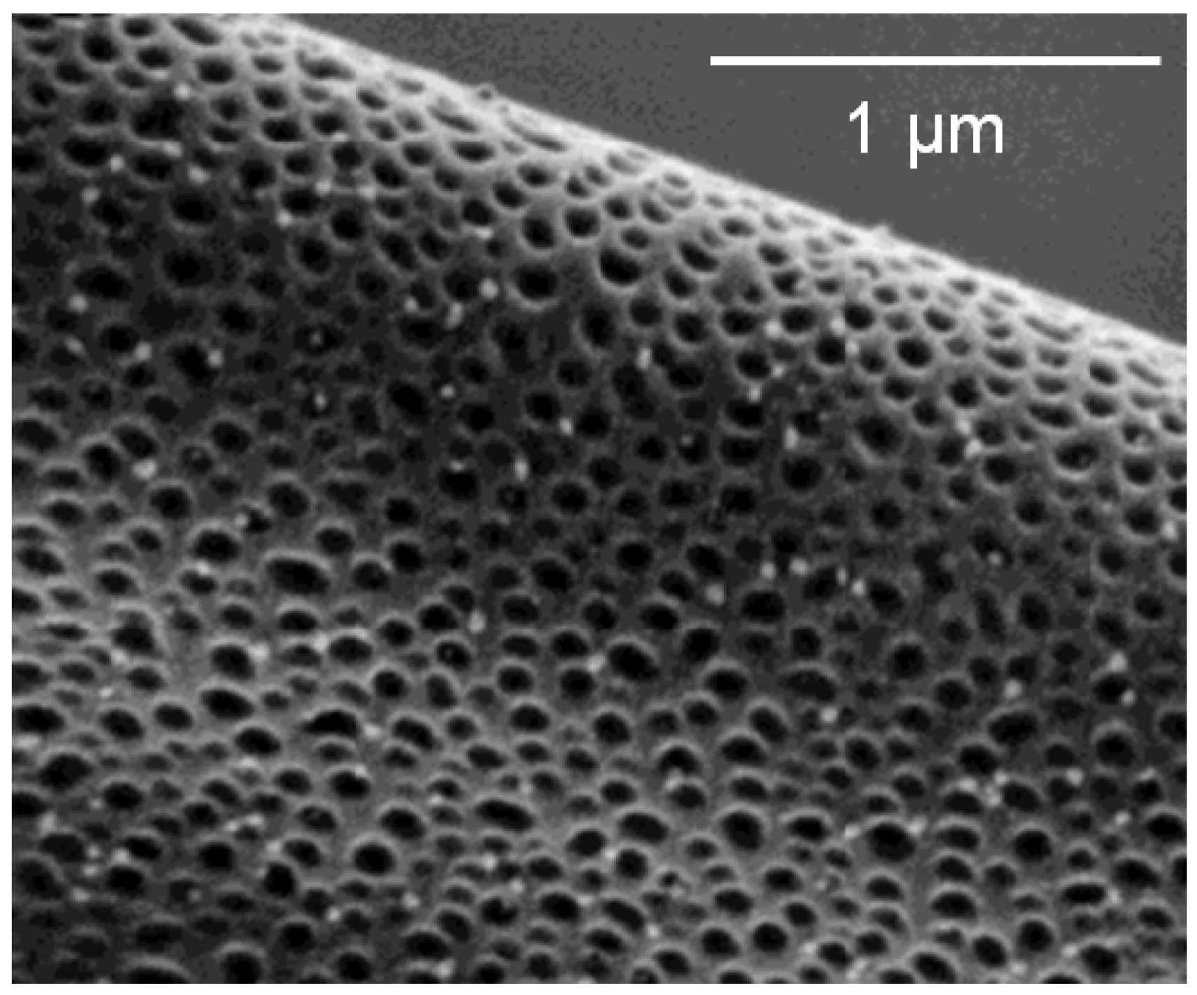
Figure 8 displays pores formed on electrospun PS fibers. Casper et al. reported controlled pore formation on PS and PMMA fibers by varying the solvent composition and solution concentration [158]. Bognitzki et al. have reported the formation of nanoscale structures on electrospun PLLA, polycarbonate and poly(vinylcarbazole) electrospun from solutions in dichloromethane [174]. The pores were elliptical in shape and in the range of 200 nm, with the longer dimension oriented with the fiber axis. The cause of pore formation was postulated to be due to the rapid phase separation of the polymer and solvent during the electrospinning process. The use of solvents with lower vapor pressures reduced pore formation. Han et al. reported pore formation on cellulose triacetate fibers [175]. Pores in the range of 200 to 500 nm were observed for the 90/10 solvent ratio of dichloromethane to ethanol. However, little or no pore formation was observed when the ethanol content was increased. Miyauchi et al. mimicked silver ragwort leaves by preparing PS fibers with high water contact angles from solvent mixtures of tetrahydrofuran (THF) and DMF. Oval-shaped pores were created along the fiber axis with a 1:1 weight ratio of the solvents. When the composition of DMF was increased to 75 wt %, short groves appeared [89]. The change in surface morphology was attributed to rapid phase separation during the electrospinning process [176]. Ma reported the formation of superhydrophobic PMMA fibers formed in a humid environment. The increased surface roughness from the nanometer sized pores and a thin coating of poly(perfluoroalkyl ethyl methacrylate) resulted in water contact angles up to 163° [177]. Cao et al. fabricated hydrophobic PLLA nanofibers with nanopores by varying the solvent ratios of DMF and dichloromethane. The resulting water contact angle depended on the pore size, with the 150 nm diameter pores having contact angles of 146.6° [178]. Zhang et al. used oxygen etching of PVA/SnCl4 to generate highly porous tin oxide fibers for ethanol sensing. Detection limits of less than 1 ppb were achieved for the porous fibers [179].
Figure 8.
Scanning electron microscopy image of electrospun PS in THF at 50% relative humidity. (Reprinted with permission from Casper et al. [158]. Copyright 2004 American Chemical Society).
Figure 8.
Scanning electron microscopy image of electrospun PS in THF at 50% relative humidity. (Reprinted with permission from Casper et al. [158]. Copyright 2004 American Chemical Society).

4.3. Nanoprotrusions
The addition of nanoparticles is another way to increase the surface area and roughness of a material and alter its properties. Lin et al. prepared superhydrophobic nanofibers containing both nanoprotrusions and nanogrooves by electrospinning PS solutions with silica nanoparticles [180]. Fiber mats containing 14.3 wt % silica exhibited the highest water contact angles (157.2°), approaching that of the lotus leaf (160°). Fang et al. applied a surface coating of silica nanoparticles and a fluorinated alkyl silane to electrospun PAN fibers. The loading of the nanoparticles and resulting surface roughness was found to be critical in generating a superhydrophobic surface [181]. Asmatulu et al. incorporated Ti02 and graphene nanoparticles into PS and polyvinyl chloride nanofibers in order to generate self-cleaning photoelectrodes for dye-sensitized solar cells [182]. Wen et al. incorporated SiO2 nanoparticles into Si02 fibers. The specific surface area increased substantially upon addition of the nanoparticles from 4.14 m2/g to 345 m2/g with 4.29% loading. These materials are expected to find important applications in dental composites [183].
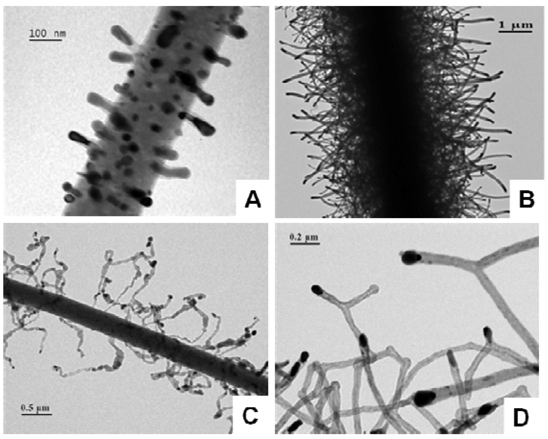
Several researchers have used two-step processes to generate nanoprotrusions on electrospun fibers. Chen et al. created nanofiber “shish kebabs” by electrospinning polycaprolactone followed by a solution crystallization of PCL or a copolymer of PCL and PEO [184]. They observed a series of nanoprotrusions from spikes to blocks oriented perpendicular to the fiber axis. The mechanism for this process was similar to the crystallization mechanism of carbon nanotube growth from a surface. Reneker et al. and Lai et al. grew carbon nanostructures from electrospun carbon nanofibers with iron and palladium nanoparticles, respectively [157,185]. In the latter work, the type of carbon dictated the morphology of the resulting nanostructure. Toluene as the carbon source yielded straight nanotubes; pyridine gave coiled and y-shaped nanotubes; and chlorobenzene formed nanoribbons. Figure 9 displays a variety of carbon nanostructures from rods to y-shaped protrusions.
Figure 9.
TEM images of carbon nanostructures grown on carbon nanofibers. (A) Short carbon nanotubes; (B) densely packed carbon nanotubes; (C) carbon nanoribbons; (D) Y-shaped carbon nanotubes. (Reprinted with permission from Lai et al. [157]. Copyright 2008 IOP Publishing).
Figure 9.
TEM images of carbon nanostructures grown on carbon nanofibers. (A) Short carbon nanotubes; (B) densely packed carbon nanotubes; (C) carbon nanoribbons; (D) Y-shaped carbon nanotubes. (Reprinted with permission from Lai et al. [157]. Copyright 2008 IOP Publishing).
He et al. grew polyaniline nanowires on electrospun carbon nanofibers via in situ polymerization of aniline. These materials had a high specific capacitance of 976.5 F g−1 at a current density of 0.4 A g−1 and are expected to serve as electrodes for supercapacitors [186]. Ostermann et al. grew V2O5 nanorods on V2O5/TiO2 nanofibers. The size of the resulting nanorods was controlled by the calcination temperature and electrospinning conditions [187]. Wang et al. grew ZnO nanostructures on TiO2 fibers. Both ZnO nanorods and nanoplates were observed [188]. Liu et al. grew ZnO nanoneedles on ZnO nanofibers using an aqueous solution process. These needle structures were over 500 nm long and had quite high aspect ratios [189]. A possible application for these materials is in high-performance field emission devices. Chen et al. used anodic aluminum oxide templates to create nanopillars on PMMA and PS electrospun fibers. The formed fibers were annealed above their glass transition temperature on the templates, cooled and removed to create ordered arrays of nanorods [88].
5. Conclusions and Outlook
Although most of the research in the electrospinning field has focused on the use of smooth 1-D nanofibers and the control of their gross morphology (fiber diameter, alignment and quality, and mat porosity), there is an ever-increasing interest in unique primary and secondary structures of nanofibers. Through control of electrospinning processing parameters such as polymer chemistry, solvent, humidity, electric field strength and collector type, a variety of hierarchical structures (helices, beads-on-a-string, core-shell or hollow fibers, and nanoporous or fibers with nanoprotrusions) can be made. These hierarchical fibers greatly expand and enhance the possible applications of electrospun fibers in the fields of nanoelectronics, sensors, MEMs devices, tissue engineering, energy harvesting and storage, meta-materials and photonics, nano/micro-fluidics, catalysis and filtration. It is expected that the range of hierarchical structures and controlled nanofiber organization/patterning will continue to grow, along with the applications of such materials. Many future advances will also most likely be driven by the applications.
Electrospinning offers many advantages for the fabrication of nanomaterials, because it is generally an inexpensive, straightforward facile process to manipulate the alignment and morphology of electrospun fibers via changes in processing conditions. Yet many challenges still remain, including the formation of sub-100-nm-sized fibers, electrospinning of materials with limited solubility, such as conjugated organic polymers, and scale-up of the electrospinning process, especially in the generation of patterned nanofibers or those with hierarchical structures [190]. In addition, more studies need to be done to better correlate processing parameters and the resulting primary and secondary hierarchical structures. Finally, the diversity and scope of electrospun materials still needs to be expanded. More reproducible methods to generate fibers into well-defined arrays with hierarchical structures are needed [191]. As these electrospinning techniques are perfected, and through interdisciplinary collaborations, electrospinning is expected to become more significant in the fields of nanotechnology and bioengineering [143].
References
- Gopal, R.; Kaur, S.; Feng, C.Y.; Chan, C.; Ramakrishna, S.; Tabe, S.; Matsuura, T. Electrospun nanofibrous polysulfone membranes as pre-filters: Particulate removal. J. Membr. Sci. 2007, 289, 210–219. [Google Scholar] [CrossRef]
- Boudriot, U.; Dersch, R.; Greiner, A.; Wendorff, J.H. Electrospinning approaches toward scaffold engineering—A brief overview. Artif. Organs 2006, 30, 785–792. [Google Scholar] [CrossRef]
- Li, W.J.; Laurencin, C.T.; Caterson, E.J.; Tuan, R.S.; Ko, F.K. Electrospun nanofibrous structure: A novel scaffold for tissue engineering. J. Biomed. Mater. Res. 2002, 60, 613–621. [Google Scholar] [CrossRef]
- Khil, M.S.; Bhattarai, S.R.; Kim, H.Y.; Kim, S.Z.; Lee, K.H. Novel fabricated matrix via electrospinning for tissue engineering. J. Biomed. Mater. Res. B 2005, 72, 117–124. [Google Scholar]
- Yoshimoto, H.; Shin, Y.M.; Terai, H.; Vacanti, J.P. A biodegradable nanofiber scaffold by electrospinning and its potential for bone tissue engineering. Biomaterials 2003, 24, 2077–2082. [Google Scholar] [CrossRef]
- Patel, A.C.; Li, S.X.; Yuan, J.M.; Wei, Y. In situ encapsulation of horseradish peroxidase in electrospun porous silica fibers for potential biosensor applications. Nano Lett. 2006, 6, 1042–1046. [Google Scholar] [CrossRef]
- Ding, B.; Kim, J.H.; Miyazaki, Y.; Shiratori, S.M. Electrospun nanofibrous membranes coated quartz crystal microbalance as gas sensor for NH3 detection. Sens. Actuators B Chem. 2004, 101, 373–380. [Google Scholar] [CrossRef]
- Tepper, G.; Kessick, R. Electrospun polymer composite fiber arrays for the detection and identification of volatile organic compounds. Sens. Actuators B Chem. 2006, 117, 205–210. [Google Scholar] [CrossRef]
- Nakata, K.; Fujii, K.; Ohkoshi, Y.; Gotoh, Y.; Nagura, M.; Numata, M.; Kamiyama, M. Poly(ethylene terephthalate) nanofibers made by sea-island-type conjugated melt spinning and laser-heated flow drawing. Macromol. Rapid Commun. 2007, 28, 792–795. [Google Scholar] [CrossRef]
- Bansal, V.; Shambaugh, R.L. On-line determination of diameter and temperature during melt blowing of polypropylene. Ind. Eng. Chem. Res. 1998, 37, 1799–1806. [Google Scholar] [CrossRef]
- Deitzel, J.M.; Kleinmeyer, J.; Harris, D.; Tan, N.C.B. The effect of processing variables on the morphology of electrospun nanofibers and textiles. Polymer 2001, 42, 8163–8170. [Google Scholar] [CrossRef]
- Hohman, M.M.; Shin, M.; Rutledge, G.; Brenner, M.P. Electrospinning and electrically forced jets. I. Stability theory. Phys. Fluids 2001, 13, 2201–2220. [Google Scholar] [CrossRef]
- Hohman, M.M.; Shin, M.; Rutledge, G.; Brenner, M.P. Electrospinning and electrically forced jets. II. Applications. Phys. Fluids 2001, 13, 2221–2236. [Google Scholar] [CrossRef]
- Huang, Z.M.; Zhang, Y.Z.; Kotaki, M.; Ramakrishna, S. A review on polymer nanofibers by electrospinning and their applications in nanocomposites. Compos. Sci. Technol. 2003, 63, 2223–2253. [Google Scholar] [CrossRef]
- Theron, A.; Zussman, E.; Yarin, A.L. Electrostatic field-assisted alignment of electrospun nanofibres. Nanotechnology 2001, 12, 384–390. [Google Scholar]
- Munir, M.M.; Widiyandari, H.; Iskandar, F.; Okuyama, K. Patterned indium tin oxide nanofiber films and their electrical and optical performance. Nanotechnology 2008, 19, 375601–375607. [Google Scholar]
- Wang, Y.; Wang, G.; Chen, L.; Li, H.; Yin, T.; Wang, B.; Lee, J.C.M.; Yu, Q. Electrospun nanofiber meshes with tailored architectures and patterns as potential tissue-engineering scaffolds. Biofabrication 2009, 1, 015001:1–015001:9. [Google Scholar]
- Zhang, D.; Chang, J. Electrospinning of three-dimensional nanofibrous tubes with controllable architectures. Nano Lett. 2008, 8, 3283–3287. [Google Scholar] [CrossRef]
- Zhang, K.; Wang, X.; Jing, D.; Yang, Y.; Zhu, M. Bionic electrospun ultrafine fibrous poly(L-lactic acid) scaffolds with a multi-scale structure. Biomed. Mater. 2009, 4, 035004:1–035004:6. [Google Scholar]
- Li, D.; Wang, Y.L.; Xia, Y.N. Electrospinning of polymeric and ceramic nanofibers as uniaxially aligned arrays. Nano Lett. 2003, 3, 1167–1171. [Google Scholar] [CrossRef]
- Beachley, V.; Wen, X. Effect of electrospinning parameters on the nanofiber diameter and length. Mater. Sci. Eng. C Mater. Biol. Appl. 2009, 29, 663–668. [Google Scholar] [CrossRef]
- Liu, L.; Dzenis, Y.A. Analysis of the effects of the residual charge and gap size on electrospun nanofiber alignment in a gap method. Nanotechnology 2008, 19, 355307:1–355307:7. [Google Scholar]
- Ishii, Y.; Sakai, H.; Murata, H. A new electrospinning method to control the number and a diameter of uniaxially aligned polymer fibers. Mater. Lett. 2008, 62, 3370–3372. [Google Scholar] [CrossRef]
- Li, D.; Xia, Y.N. Electrospinning of nanofibers: Reinventing the wheel? Adv. Mater. 2004, 16, 1151–1170. [Google Scholar] [CrossRef]
- Li, M.Y.; Mondrinos, M.J.; Gandhi, M.R.; Ko, F.K.; Weiss, A.S.; Lelkes, P.I. Electrospun protein fibers as matrices for tissue engineering. Biomaterials 2005, 26, 5999–6008. [Google Scholar] [CrossRef]
- Li, J.; He, A.; Zheng, J.; Han, C.C. Gelatin and gelatin-hyaluronic acid nanofibrous membranes produced by electrospinning of their aqueous solutions. Biomacromolecules 2006, 7, 2243–2247. [Google Scholar] [CrossRef]
- Li, C.M.; Vepari, C.; Jin, H.J.; Kim, H.J.; Kaplan, D.L. Electrospun silk-BMP-2 scaffolds for bone tissue engineering. Biomaterials 2006, 27, 3115–3124. [Google Scholar] [CrossRef]
- Zhang, Y.Z.; Ouyang, H.W.; Lim, C.T.; Ramakrishna, S.; Huang, Z.M. Electrospinning of gelatin fibers and gelatin/PCL composite fibrous scaffolds. J. Biomed. Mater. Res. B 2005, 72, 156–165. [Google Scholar]
- Zhang, Y.Z.; Venugopal, J.; Huang, Z.M.; Lim, C.T.; Ramakrishna, S. Crosslinking of the electrospun gelatin nanofibers. Polymer 2006, 47, 2911–2917. [Google Scholar] [CrossRef]
- Zhong, S.; Teo, W.E.; Zhu, X.; Beuerman, R.W.; Ramakrishna, S.; Yung, L.Y.L. An aligned nanofibrous collagen scaffold by electrospinning and its effects on in vitro fibroblast culture. J. Biomed. Mater. Res A 2006, 79, 456–463. [Google Scholar]
- Matthews, J.A.; Wnek, G.E.; Simpson, D.G.; Bowlin, G.L. Electrospinning of collagen nanofibers. Biomacromolecules 2002, 3, 232–238. [Google Scholar] [CrossRef]
- Zhou, Z.P.; Lai, C.L.; Zhang, L.F.; Qian, Y.; Hou, H.Q.; Reneker, D.H.; Fong, H. Development of carbon nanofibers from aligned electrospun polyacrylonitrile nanofiber bundles and characterization of their microstructural, electrical, and mechanical properties. Polymer 2009, 50, 2999–3006. [Google Scholar] [CrossRef]
- Zhmayev, E.; Zhou, H.; Joo, Y.L. Modeling of non-isothermal polymer jets in melt electrospinning. J. Non-Newton. Fluid Mech. 2008, 153, 95–108. [Google Scholar] [CrossRef]
- Zhang, X.; Thavasi, V.; Mhaisalkar, S.G.; Ramakrishna, S. Novel hollow mesoporous 1D TiO2 nanofibers as photovoltaic and photocatalytic materials. Nanoscale 2012, 4, 1707–1716. [Google Scholar] [CrossRef]
- Wu, H.; Hu, L.; Rowell, M.W.; Kong, D.; Cha, J.J.; McDonough, J.R.; Zhu, J.; Yang, Y.; McGehee, M.D.; Cui, Y. Electrospun metal nanofiber webs as high-performance transparent electrode. Nano Lett. 2010, 10, 4242–4248. [Google Scholar]
- Sahay, R.; Kumar, P.S.; Sridhar, R.; Sundaramurthy, J.; Venugopal, J.; Mhaisalkar, S.G.; Ramakrishna, S. Electrospun composite nanofibers and their multifaceted applications. J. Mater. Chem. 2012, 22, 12953–12971. [Google Scholar]
- Ramakrishna, S.; Jose, R.; Archana, P.S.; Nair, A.S.; Balamurugan, R.; Venugopal, J.; Teo, W.E. Science and engineering of electrospun nanofibers for advances in clean energy, water filtration, and regenerative medicine. J. Mater. Sci. 2010, 45, 6283–6312. [Google Scholar] [CrossRef]
- Greiner, A.; Wendorff, J.H. Electrospinning: A fascinating method for the preparation of ultrathin fibres. Angew. Chem. Int. Ed. 2007, 46, 5670–5703. [Google Scholar] [CrossRef]
- Dersch, R.; Graeser, M.; Greiner, A.; Wendorff, J.H. Electrospinning of nanofibres: Towards new techniques, functions, and applications. Aust. J. Chem. 2007, 60, 719–728. [Google Scholar] [CrossRef]
- Theron, S.A.; Zussman, E.; Yarin, A.L. Experimental investigation of the governing parameters in the electrospinning of polymer solutions. Polymer 2004, 45, 2017–2030. [Google Scholar] [CrossRef]
- Shin, Y.M.; Hohman, M.M.; Brenner, M.P.; Rutledge, G.C. Experimental characterization of electrospinning: the electrically forced jet and instabilities. Polymer 2001, 42, 9955–9967. [Google Scholar]
- Fridrikh, S.V.; Yu, J.H.; Brenner, M.P.; Rutledge, G.C. Controlling the fiber diameter during electrospinning. Phys. Rev. Lett. 2003, 90, 144502:1–144502:4. [Google Scholar]
- Demir, M.M.; Yilgor, I.; Yilgor, E.; Erman, B. Electrospinning of polyurethane fibers. Polymer 2002, 43, 3303–3309. [Google Scholar] [CrossRef]
- Kim, H.W.; Yu, H.S.; Lee, H.H. Nanofibrous matrices of poly(lactic acid) and gelatin polymeric blends for the improvement of cellular responses. J. Biomed. Mater. Res. A 2008, 87, 25–32. [Google Scholar]
- Zong, X.H.; Ran, S.F.; Kim, K.S.; Fang, D.F.; Hsiao, B.S.; Chu, B. Structure and morphology changes during in vitro degradation of electrospun poly(glycolide-co-lactide) nanofiber membrane. Biomacromolecules 2003, 4, 416–423. [Google Scholar] [CrossRef]
- Reneker, D.H.; Kataphinan, W.; Theron, A.; Zussman, E.; Yarin, A.L. Nanofiber garlands of polycaprolactone by electrospinning. Polymer 2002, 43, 6785–6794. [Google Scholar] [CrossRef]
- Liu, J.; Rasheed, A.; Dong, H.; Carr, W.W.; Dadmun, M.D.; Kumar, S. Electrospun micro- and nanostructured polymer particles. Macromol. Chem. Phys. 2008, 209, 2390–2398. [Google Scholar]
- Liu, J.; Kumar, S. Microscopic polymer cups by electrospinning. Polymer 2005, 46, 3211–3214. [Google Scholar] [CrossRef]
- Fong, H.; Chun, I.; Reneker, D.H. Beaded nanofibers formed during electrospinning. Polymer 1999, 40, 4585–4592. [Google Scholar] [CrossRef]
- Zong, X.H.; Kim, K.; Fang, D.F.; Ran, S.F.; Hsiao, B.S.; Chu, B. Structure and process relationship of electrospun bioabsorbable nanofiber membranes. Polymer 2002, 43, 4403–4412. [Google Scholar] [CrossRef]
- Baiguera, S.; Del Gaudio, C.; Fioravanzo, L.; Bianco, A.; Grigioni, M.; Folin, M. In vitro astrocyte and cerebral endothelial cell response to electrospun poly(epsilon-caprolactone) mats of different architecture. J. Mater. Sci. Mater. Med. 2010, 21, 1353–1362. [Google Scholar] [CrossRef]
- Balguid, A.; Mol, A.; van Marion, M.H.; Bank, R.A.; Bouten, C.V.C.; Baaijens, F.P.T. Tailoring fiber diameter in electrospun poly(epsilon-caprolactone) scaffolds for optimal cellular infiltration in cardiovascular tissue engineering. Tissue Eng. A 2009, 15, 437–444. [Google Scholar]
- Nam, J.; Huang, Y.; Agarwal, S.; Lannutti, J. Improved cellular infiltration in electrospun fiber via engineered porosity. Tissue Eng. 2007, 13, 2249–2257. [Google Scholar] [CrossRef]
- Leong, M.F.; Rasheed, M.Z.; Lim, T.C.; Chian, K.S. In vitro cell infiltration and in vivo cell infiltration and vascularization in a fibrous, highly porous poly(D,L-lactide) scaffold fabricated by cryogenic electrospinning technique. J. Biomed. Mater. Res. A 2009, 91, 231–240. [Google Scholar]
- Huang, Y.Y.; Wang, D.Y.; Chang, L.L.; Yang, Y.C. Fabricating microparticles/nanofibers composite and nanofiber scaffold with controllable pore size by rotating multichannel electrospinning. J. Biomater. Sci. Polym. E. 2010, 21, 1503–1514. [Google Scholar] [CrossRef]
- Kim, S.J.; Jang, D.H.; Park, W.H.; Min, B.M. Fabrication and characterization of 3-dimensional PLGA nanofiber/microfiber composite scaffolds. Polymer 2010, 51, 1320–1327. [Google Scholar]
- Pham, Q.P.; Sharma, U.; Mikos, A.G. Electrospun poly(epsilon-caprolactone) microfiber and multilayer nanofiber/microfiber scaffolds: Characterization of scaffolds and measurement of cellular infiltration. Biomacromolecules 2006, 7, 2796–2805. [Google Scholar] [CrossRef]
- Ju, Y.M.; Choi, J.S.; Atala, A.; Yoo, J.J.; Lee, S.J. Bilayered scaffold for engineering cellularized blood vessels. Biomaterials 2010, 31, 4313–4321. [Google Scholar] [CrossRef]
- Thorvaldsson, A.; Stenhamre, H.; Gatenholm, P.; Walkenstrom, P. Electrospinning of highly porous scaffolds for cartilage regeneration. Biomacromolecules 2008, 9, 1044–1049. [Google Scholar] [CrossRef]
- Baker, B.M.; Gee, A.O.; Metter, R.B.; Nathan, A.S.; Marklein, R.A.; Burdick, J.A.; Mauck, R.L. The potential to improve cell infiltration in composite fiber-aligned electrospun scaffolds by the selective removal of sacrificial fibers. Biomaterials 2008, 29, 2348–2358. [Google Scholar] [CrossRef]
- Katta, P.; Alessandro, M.; Ramsier, R.D.; Chase, G.G. Continuous electrospinning of aligned polymer nanofibers onto a wire drum collector. Nano Lett. 2004, 4, 2215–2218. [Google Scholar] [CrossRef]
- Li, D.; Ouyang, G.; McCann, J.T.; Xia, Y.N. Collecting electrospun nanofibers with patterned electrodes. Nano Lett. 2005, 5, 913–916. [Google Scholar] [CrossRef]
- Sundaray, B.; Subramanian, V.; Natarajan, T.S.; Xiang, R.Z.; Chang, C.C.; Fann, W.S. Electrospinning of continuous aligned polymer fibers. Appl. Phys. Lett. 2004, 84, 1222–1224. [Google Scholar] [CrossRef]
- Teo, W.E.; Ramakrishna, S. A review on electrospinning design and nanofibre assemblies. Nanotechnology 2006, 17, R89–R106. [Google Scholar]
- Ner, Y.; Asemota, C.; Olson, J.R.; Sotzing, G.A. Nanofiber alignment on a flexible substrate: Hierarchical order from macro to nano. ACS Appl. Mater. Interfaces 2009, 1, 2093–2097. [Google Scholar] [CrossRef]
- Li, D.; Wang, Y.L.; Xia, Y.N. Electrospinning nanofibers as uniaxially aligned arrays and layer-by-layer stacked films. Adv. Mater. 2004, 16, 361–366. [Google Scholar] [CrossRef]
- Zussman, E.; Theron, A.; Yarin, A.L. Formation of nanofiber crossbars in electrospinning. Appl. Phys. Lett. 2003, 82, 973–975. [Google Scholar]
- Lin, J.; Wang, X.; Ding, B.; Yu, J.; Sun, G.; Wang, M. Biomimicry via electrospinning. Crit. Rev. Solid State Mater. Sci. 2012, 37, 94–114. [Google Scholar] [CrossRef]
- Ding, Z.; Salim, A.; Ziaie, B. Selective nanofiber deposition through field-enhanced electrospinning. Langmuir 2009, 25, 9648–9652. [Google Scholar] [CrossRef]
- Zucchelli, A.; Fabiani, D.; Gualandi, C.; Focarete, M.L. An innovative and versatile approach to design highly porous, patterned, nanofibrous polymeric materials. J. Mater. Sci. 2009, 44, 4969–4975. [Google Scholar] [CrossRef]
- Ye, X.Y.; Huang, X.J.; Xu, Z.K. Nanofibrous mats with bird’s nest patterns by electrospinning. Chin. J. Polym. Sci. 2012, 30, 130–137. [Google Scholar] [CrossRef]
- Sun, D.H.; Chang, C.; Li, S.; Lin, L.W. Near-field electrospinning. Nano Lett. 2006, 6, 839–842. [Google Scholar] [CrossRef]
- Chang, C.; Limkrailassiri, K.; Lin, L. Continuous near-field electrospinning for large area deposition of orderly nanofiber patterns. Appl. Phys. Lett. 2008, 93, 123111:1–123111:3. [Google Scholar]
- Zheng, G.; Li, W.; Wang, X.; Wu, D.; Sun, D.; Lin, L. Precision deposition of a nanofibre by near-field electrospinning. J. Phys. D Appl. Phys. 2010, 43, 415501:1–415501:6. [Google Scholar]
- Kameoka, J.; Craighead, H.G. Fabrication of oriented polymeric nanofibers on planar surfaces by electrospinning. Appl. Phys. Lett. 2003, 83, 371–373. [Google Scholar] [CrossRef]
- Kameoka, J.; Orth, R.; Yang, Y.N.; Czaplewski, D.; Mathers, R.; Coates, G.W.; Craighead, H.G. A scanning tip electrospinning source for deposition of oriented nanofibres. Nanotechnology 2003, 14, 1124–1129. [Google Scholar] [CrossRef]
- Tao, S.; Li, G.; Yin, J. Fluorescent nanofibrous membranes for trace detection of TNT vapor. J. Mater. Chem. 2007, 17, 2730–2736. [Google Scholar] [CrossRef]
- Yang, D.; Lu, B.; Zhao, Y.; Jiang, X. Fabrication of aligned fibirous arrays by magnetic electrospinning. Adv. Mater. 2007, 19, 3702–3706. [Google Scholar] [CrossRef]
- Shi, J.; Wang, L.; Chen, Y. Microcontact printing and lithographic patterning of electrospun nanofibers. Langmuir 2009, 25, 6015–6018. [Google Scholar] [CrossRef]
- Carlberg, B.; Wang, T.; Liu, J. Direct photolithographic patterning of electrospun films for defined nanofibrillar microarchitectures. Langmuir 2010, 26, 2235–2239. [Google Scholar] [CrossRef]
- Sharma, C.S.; Sharma, A.; Madou, M. Multiscale carbon structures fabricated by direct micropatterning of electrospun mats of su-8 photoresist nanofibers. Langmuir 2010, 26, 2218–2222. [Google Scholar] [CrossRef]
- Ding, B.; Wang, M.; Wang, X.; Yu, J.; Sun, G. Electrospun nanomaterials for ultrasensitive sensors. Mater. Today 2010, 13, 16–27. [Google Scholar]
- Charra, F.; Cousty, J. Surface-induced chirality in a self-assembled monolayer of discotic liquid crystal. Phys. Rev. Lett. 1998, 80, 1682–1685. [Google Scholar] [CrossRef]
- Schull, G.; Douillard, L.; Fiorini-Debuisschert, C.; Charra, F.; Mathevet, F.; Kreher, D.; Attias, A.J. Single-molecule dynamics in a self-assembled 2D molecular sieve. Nano Lett. 2006, 6, 1360–1363. [Google Scholar] [CrossRef]
- Yang, W.Y.; Lee, E.; Lee, M. Tubular organization with coiled ribbon from amphiphilic rigid-flexible macrocycle. J. Am. Chem. Soc. 2006, 128, 3484–3485. [Google Scholar] [CrossRef]
- Akagi, K.; Piao, G.; Kaneko, S.; Sakamaki, K.; Shirakawa, H.; Kyotani, M. Helical polyacetylene synthesized with a chiral nematic reaction field. Science 1998, 282, 1683–1686. [Google Scholar] [CrossRef]
- Wang, J.; Zheng, Y.; Nie, F.Q.; Zhai, J.; Jiang, L. Air bubble bursting effect of lotus leaf. Langmuir 2009, 25, 14129–14134. [Google Scholar]
- Chen, J.T.; Chen, W.L.; Fan, P.W. Hierarchical structures by wetting porous templates with electrospun polymer fibers. ACS Macro Lett. 2012, 1, 41–46. [Google Scholar] [CrossRef]
- Miyauchi, Y.; Ding, B.; Shiratori, S. Fabrication of a silver-ragwort-leaf-like super-hydrophobic micro/nanoporous fibrous mat surface by electrospinning. Nanotechnology 2006, 17, 5151–5156. [Google Scholar] [CrossRef]
- Li, X.; Ding, B.; Lin, J.; Yu, J.; Sun, G. Enhanced mechanical properties of superhydrophobic microfibrous polystyrene mats via polyamide 6 nanofibers. J. Phys. Chem. C 2009, 113, 20425–20457. [Google Scholar]
- Huang, Z.M.; Zhang, Y.Z.; Ramakrishna, S. Double-layered composite nanofibers and their mechanical performance. J. Polym. Sci. B Polym. Phys. 2005, 43, 2852–2861. [Google Scholar]
- Jiang, H.L.; Hu, Y.Q.; Li, Y.; Zhao, P.C.; Zhu, K.J.; Chen, W.L. A facile technique to prepare biodegradable coaxial electrospun nanofibers for controlled release of bioactive agents. J. Control. Release 2005, 108, 237–243. [Google Scholar] [CrossRef]
- Sun, B.; Duan, B.; Yuan, X.Y. Preparation of core/shell PVP/PLA ultrafine fibers by coaxial electrospinning. J. Appl. Polym. Sci. 2006, 102, 39–45. [Google Scholar] [CrossRef]
- Srikar, R.; Yarin, A.L.; Megaridis, C.M.; Bazilevsky, A.V.; Kelley, E. Desorption-limited mechanism of release from polymer nanofibers. Langmuir 2008, 24, 965–974. [Google Scholar] [CrossRef]
- Moghe, A.K.; Gupta, B.S. Co-axial electrospinning for nanofiber structures: Preparation and applications. Polym. Rev. 2008, 48, 353–377. [Google Scholar]
- Zhang, Y.Z.; Venugopal, J.; Huang, Z.M.; Lim, C.T.; Ramakrishna, S. Characterization of the surface biocompatibility of the electrospun PCL-collagen nanofibers using fibroblasts. Biomacromolecules 2005, 6, 2583–2589. [Google Scholar] [CrossRef]
- Cao, G.; Brinker, C.J. Annual Review of Nano Research; World Scientific: Hackensack, NJ, USA, 2006. [Google Scholar]
- Sun, Z.C.; Zussman, E.; Yarin, A.L.; Wendorff, J.H.; Greiner, A. Compound core-shell polymer nanofibers by co-electrospinning. Adv. Mater. 2003, 15, 1929–1932. [Google Scholar] [CrossRef]
- Yu, J.H.; Fridrikh, S.V.; Rutledge, G.C. Production of submicrometer diameter fibers by two-fluid electrospinning. Adv. Mater. 2004, 16, 1562–1566. [Google Scholar]
- Greiner, A.; Wendorff, J.H.; Yarin, A.L.; Zussman, E. Biohybrid nanosystems with polymer nanofibers and nanotubes. Appl. Microbiol. Biotechnol. 2006, 71, 387–393. [Google Scholar] [CrossRef]
- Zussman, E.; Yarin, A.L.; Bazilevsky, A.V.; Avrahami, R.; Feldman, M. Electrospun polyacrylonitrile/poly (methyl methacrylate)-derived turbostratic carbon micro-/nanotubes. Adv. Mater. 2006, 18, 348–353. [Google Scholar] [CrossRef]
- Loscertales, I.G.; Barrero, A.; Marquez, M.; Spretz, R.; Velarde-Ortiz, R.; Larsen, G. Electrically forced coaxial nanojets for one-step hollow nanofiber design. J. Am. Chem. Soc. 2004, 126, 5376–5377. [Google Scholar]
- Li, D.; Xia, Y.N. Direct fabrication of composite and ceramic hollow nanofibers by electrospinning. Nano Lett. 2004, 4, 933–938. [Google Scholar] [CrossRef]
- Choi, S.H.; Ankonina, G.; Youn, D.Y.; Oh, S.G.; Hong, J.M.; Rothschild, A.; Kim, I.D. Hollow ZnO nanofibers fabricated using electrospun polymer templates and their electronic transport properties. Acs Nano 2009, 3, 2623–2631. [Google Scholar]
- Gao, Y.; Li, X.; Gong, J.; Fan, B.; Su, Z.; Qu, L. Polyaniline nanotubes prepared using fiber mats membrane as the template and their gas-response behavior. J. Phys. Chem. C 2008, 112, 8215–8222. [Google Scholar]
- Park, J.Y.; Choi, S.W.; Lee, J.W.; Lee, C.; Kim, S.S. Synthesis and gas sensing properties of TiO2-ZnO core-shell nanofibers. J. Am. Ceram. Soc. 2009, 92, 2551–2554. [Google Scholar] [CrossRef]
- Zhan, S.; Chen, D.; Jiao, X.; Tao, C. Long TiO2 hollow fibers with mesoporous walls: Sol-gel combined electrospun fabrication and photocatalytic properties. J. Phys. Chem. B 2006, 110, 11199–11214. [Google Scholar] [CrossRef]
- Zhang, Y.Z.; Wang, X.; Feng, Y.; Li, J.; Lim, C.T.; Ramakrishna, S. Coaxial electrospinning of (fluorescein isothiocyanate-conjugated bovine serum albumin)-encapsulated poly(epsilon-caprolactone)nanofibers for sustained release. Biomacromolecules 2006, 7, 1049–1057. [Google Scholar] [CrossRef]
- Townsend-Nicholson, A.; Jayasinghe, S.N. Cell electrospinning: A unique biotechnique for encapsulating living organisms for generating active biological microthreads/scaffolds. Biomacromolecules 2006, 7, 3364–3369. [Google Scholar] [CrossRef]
- Klein, S.; Kuhn, J.; Avrahami, R.; Tarre, S.; Beliavski, M.; Green, M.; Zussman, E. Encapsulation of bacterial cells in electrospun microtubes. Biomacromolecules 2009, 10, 1751–1756. [Google Scholar] [CrossRef]
- Han, D.; Steckl, A.J. Superhydrophobic and oleophobic fibers by coaxial electrospinning. Langmuir 2009, 25, 9454–9462. [Google Scholar] [CrossRef]
- Bazilevsky, A.V.; Yarin, A.L.; Megaridis, C.M. Co-electrospinning of core-shell fibers using a single-nozzle technique. Langmuir 2007, 23, 2311–2314. [Google Scholar] [CrossRef]
- Kim, C.; Jeong, Y.I.; Ngoc, B.T.N.; Yang, K.S.; Kojima, M.; Kim, Y.A.; Endo, M.; Lee, J.W. Synthesis and characterization of porous carbon nanofibers with hollow cores through the thermal treatment of electrospun copolymeric nanofiber webs. Small 2007, 3, 91–95. [Google Scholar] [CrossRef]
- Zander, N.; Strawhecker, K.; Orlicki, J.; Rawlett, A.; Beebe, T. Coaxial electrospun poly(methyl methacrylate)-polyacrylonitrile nanofibers: Atomic force microscopy and compositional characterization. J. Phys. Chem. B 2011, 115, 12441–12447. [Google Scholar] [CrossRef]
- Sanders, E.H.; Kloefkorn, R.; Bowlin, G.L.; Simpson, D.G.; Wnek, G.E. Two-phase electrospinning from a single electrified jet: Microencapsulation of aqueous reservoirs in poly(ethylene-co-vinyl acetate) fibers. Macromolecules 2003, 36, 3803–3805. [Google Scholar] [CrossRef]
- Zhang, Y.Z.; Huang, Z.M.; Xu, X.J.; Lim, C.T.; Ramakrishna, S. Preparation of core-shell structured PCL-r-gelatin Bi-component nanofibers by coaxial electrospinning. Chem. Mater. 2004, 16, 3406–3409. [Google Scholar] [CrossRef]
- Li, D.; Babel, A.; Jenekhe, S.A.; Xia, Y.N. Nanofibers of conjugated polymers prepared by electrospinning with a two-capillary spinneret. Adv. Mater. 2004, 16, 2062–2066. [Google Scholar] [CrossRef]
- Kalra, V.; Kakad, P.A.; Mendez, S.; Ivannikov, T.; Kamperman, M.; Joo, Y.L. Self-assembled structures in electrospun poly(styrene-block-isoprene) fibers. Macromolecules 2006, 39, 5453–5457. [Google Scholar] [CrossRef]
- Ruotsalainen, T.; Turku, J.; Heikkila, P.; Ruokolainen, J.; Nykanen, A.; Laitinen, T.; Torkkeli, M.; Serimaa, R.; ten Brinke, G.; Harlin, A.; Ikkala, O. Towards internal structuring of electrospun fibers by hierarchical self-assembly of polymeric comb-shaped supramolecules. Adv. Mater. 2005, 17, 1048–1052. [Google Scholar] [CrossRef]
- Ma, M.L.; Krikorian, V.; Yu, J.H.; Thomas, E.L.; Rutledge, G.C. Electrospun polymer nanofibers with internal periodic structure obtained by microphase separation of cylindrically confined block copolymers. Nano Lett. 2006, 6, 2969–2972. [Google Scholar] [CrossRef]
- Ma, M.L.; Thomas, E.L.; Rutledge, G.C.; Yu, B.; Li, B.H.; Jin, Q.H.; Ding, D.T.; Shi, A.C. Gyroid-forming diblock copolymers confined in cylindrical geometry: A case of extreme makeover for domain morphology. Macromolecules 2010, 43, 3061–3071. [Google Scholar] [CrossRef] [Green Version]
- Ma, M.L.; Hill, R.M.; Lowery, J.L.; Fridrikh, S.V.; Rutledge, G.C. Electrospun poly(styrene-block-dimethylsiloxane) block copolymer fibers exhibiting superhydrophobicity. Langmuir 2005, 21, 5549–5554. [Google Scholar]
- Kalra, V.; Mendez, S.; Lee, J.H.; Nguyen, H.; Marquez, M.; Joo, Y.L. Confined assembly in coaxially electrospun block-copolymer fibers. Adv. Mater. 2006, 18, 3299–3203. [Google Scholar]
- Grevin, B.; Rannou, P. Electrochemistry: Arrays of polymer nanowires. Nat. Mater. 2004, 3, 503–504. [Google Scholar] [CrossRef]
- di Benedetto, F.; Camposeo, A.; Pagliara, S.; Mele, E.; Persano, L.; Stabile, R.; Cingolani, R.; Pisignano, D. Patterning of light-emitting conjugated polymer nanofibres. Nat. Nanotechnol. 2008, 3, 614–619. [Google Scholar] [CrossRef]
- Babel, A.; Li, D.; Xia, Y.N.; Jenekhe, S.A. Electrospun nanofibers of blends of conjugated polymers: Morphology, optical properties, and field-effect transistors. Macromolecules 2005, 38, 4705–4711. [Google Scholar] [CrossRef]
- Gupta, V.; Miura, N. High performance electrochemical supercapacitor from electrochemically synthesized nanostructured polyaniline. Mater. Lett. 2006, 60, 1466–1469. [Google Scholar] [CrossRef]
- Li, W.G.; Wang, H.L. Oligomer-assisted synthesis of chiral polyaniline nanofibers. J. Am. Chem. Soc. 2004, 126, 2278–2279. [Google Scholar] [CrossRef]
- Veretennikov, I.; Indeikina, A.; Chang, H.C.; Marquez, M.; Suib, S.L.; Giraldo, O. Mechanism for helical gel formation from evaporation of colloidal solutions. Langmuir 2002, 18, 8792–8798. [Google Scholar] [CrossRef]
- Kong, X.Y.; Wang, Z.L. Spontaneous polarization-induced nanohelixes, nanosprings, and nanorings of piezoelectric nanobelts. Nano Lett. 2003, 3, 1625–1631. [Google Scholar] [CrossRef]
- Zhang, H.F.; Wang, C.M.; Buck, E.C.; Wang, L.S. Synthesis, characterization, and manipulation of helical SiO2 nanosprings. Nano Lett. 2003, 3, 577–580. [Google Scholar] [CrossRef]
- Xin, Y.; Huang, Z.H.; Yan, E.Y.; Zhang, W.; Zhao, Q. Controlling poly(p-phenylene vinylene)/poly(vinyl pyrrolidone) composite nanofibers in different morphologies by electrospinning. Appl. Phys. Lett. 2006, 89, 053101:1–053101:3. [Google Scholar]
- Kessick, R.; Tepper, G. Microscale polymeric helical structures produced by electrospinning. Appl. Phys. Lett. 2004, 84, 4807–4809. [Google Scholar] [CrossRef]
- Lin, T.; Wang, H.X.; Wang, X.G. Self-crimping bicomponent nanofibers electrospun from polyacrylonitrile and elastomeric polyurethane. Adv. Mater. 2005, 17, 2699–2703. [Google Scholar] [CrossRef]
- Chen, S.L.; Hou, H.Q.; Hu, P.; Wendorff, J.H.; Greiner, A.; Agarwal, S. Polymeric nanosprings by bicomponent electrospinning. Macromol. Mater. Eng. 2009, 294, 265–271. [Google Scholar] [CrossRef]
- Shin, M.K.; Kim, S.I.; Kim, S.J. Controlled assembly of polymer nanofibers: From helical springs to fully extended. Appl. Phys. Lett. 2006, 88, 223109:1–223109:3. [Google Scholar]
- Canejo, J.P.; Borges, J.P.; Godinho, M.H.; Brogueira, P.; Teixeira, P.I.C.; Terentjev, E.M. Helical twisting of electrospun liquid crystalline cellulose micro- and nanofibers. Adv. Mater. 2008, 20, 4821–4825. [Google Scholar] [CrossRef]
- Han, T.; Reneker, D.H.; Yarin, A.L. Buckling of jets in electrospinning. Polymer 2007, 48, 6064–6076. [Google Scholar] [CrossRef]
- Xin, Y.; Reneker, D.H. Garland formation process in electrospinning. Polymer 2012, 53, 3629–3635. [Google Scholar] [CrossRef]
- Xin, Y.; Reneker, D.H. Hierarchical polystyrene patterns produced by electrospinning. Polymer 2012, 53, 4254–4261. [Google Scholar] [CrossRef]
- Reneker, D.H.; Yarin, A.L. Electrospinning jets and polymer nanofibers. Polymer 2008, 49, 2387–2425. [Google Scholar] [CrossRef]
- Yu, J.; Qiu, Y.; Zha, X.; Yu, M.; Yu, J.; Rafique, J.; Yin, J. Production of aligned helical polymer nanofibers by electrospinning. Eur. Polym. J. 2008, 44, 2838–2844. [Google Scholar] [CrossRef]
- Pagliara, S.; Camposeo, A.; Cingolani, R.; Pisignano, D. Hierarchical assembly of light-emitting polymer nanofibers in helical morphologies. Appl. Phys. Lett. 2009, 95, 263301:1–263301:3. [Google Scholar]
- Xin, Y.; Huang, Z.; Jiang, Z.; Che, L.; Sun, M.; Wang, C.; Liu, S. Fluorescent poly(p-phenylene vinylene)/poly(ethylene oxide) nanofibers obtained by electrospinning. J. Polym. Res. 2011, 18, 477–482. [Google Scholar] [CrossRef]
- Tang, C.C.; Chen, J.C.; Long, Y.Z.; Yin, H.X.; Sun, B.; Zhang, H.D. Preparation of curled microfibers by electrospinning with tip collector. Chin. Phys. Lett. 2011, 28, 056801:1–056801:3. [Google Scholar]
- Reneker, D.H.; Yarin, A.L.; Fong, H.; Koombhongse, S. Bending instability of electrically charged liquid jets of polymer solutions in electrospinning. J. Appl. Phys. 2000, 87, 4531–4547. [Google Scholar] [CrossRef]
- Zhang, B.; Li, C.; Chang, M. Curled poly(ethylene glycol terephthalate)/poly(ethylene propanediol terephthalate) nanofibers produced by side-by-side electrospinning. Polym. J. 2009, 41, 252–253. [Google Scholar]
- Koombhongse, S.; Liu, W.X.; Reneker, D.H. Flat polymer ribbons and other shapes by electrospinning. J. Polym. Sci. B Polym. Phys. 2001, 39, 2598–2606. [Google Scholar] [CrossRef]
- Barnes, C.P.; Smith, M.J.; Bowlin, G.L.; Sell, S.A.; Tang, T.; Matthews, J.A.; Simpson, D.G.; Nimtz, J.C. Feasibility of electrospinning the globular proteins hemoglobin and myoglobin. J. Eng. Fibers Fabr. 2006, 1, 16–29. [Google Scholar]
- Jiang, L.; Zhao, Y.; Zhai, J. A lotus-leaf-like superhydrophobic surface: A porous microsphere/nanofiber composite film prepared by electrohydrodynamics. Angew. Chem. Int. Ed. 2004, 43, 4338–4341. [Google Scholar] [CrossRef]
- Ma, M.L.; Mao, Y.; Gupta, M.; Gleason, K.K.; Rutledge, G.C. Superhydrophobic fabrics produced by electrospinning and chemical vapor deposition. Macromolecules 2005, 38, 9742–9748. [Google Scholar] [CrossRef]
- Bin, D.; Chunrong, L.; Miyauchi, Y.; Kuwaki, O.; Shiratori, S. Formation of novel 2D polymer nanowebs via electrospinning. Nanotechnology 2006, 17, 3685–3691. [Google Scholar] [CrossRef]
- Wang, X.F.; Ding, B.; Yu, J.Y.; Wang, M.R.; Pan, F.K. A highly sensitive humidity sensor based on a nanofibrous membrane coated quartz crystal microbalance. Nanotechnology 2010, 21, 055502–055507. [Google Scholar] [CrossRef]
- Yang, S.B.; Wang, X.F.; Ding, B.; Yu, J.Y.; Qian, J.F.; Sun, G. Controllable fabrication of soap-bubble-like structured polyacrylic acid nano-nets via electro-netting. Nanoscale 2011, 3, 564–568. [Google Scholar] [CrossRef]
- Wang, X.F.; Ding, B.; Yu, J.Y.; Yang, J.M. Large-scale fabrication of two-dimensional spider-web-like gelatin nano-nets via electro-netting. Colloid Surf. B 2011, 86, 345–352. [Google Scholar] [CrossRef]
- Wang, X.F.; Ding, B.; Yu, J.Y.; Si, Y.; Yang, S.B.; Sun, G. Electro-netting: Fabrication of two-dimensional nano-nets for highly sensitive trimethylamine sensing. Nanoscale 2011, 3, 911–915. [Google Scholar] [CrossRef]
- Lai, C.; Guo, Q.H.; Wu, X.F.; Reneker, D.H.; Hou, H. Growth of carbon nanostructures on carbonized electrospun nanofibers with palladium nanoparticles. Nanotechnology 2008, 19, 195303–195309. [Google Scholar] [CrossRef]
- Casper, C.L.; Stephens, J.S.; Tassi, N.G.; Chase, D.B.; Rabolt, J.F. Controlling surface morphology of electrospun polystyrene fibers: Effect of humidity and molecular weight in the electrospinning process. Macromolecules 2004, 37, 573–578. [Google Scholar] [CrossRef]
- Zheng, J.F.; Zhang, H.Y.; Zhao, Z.G.; Han, C.C. Construction of hierarchical structures by electrospinning or electrospraying. Polymer 2012, 53, 546–554. [Google Scholar] [CrossRef]
- Boker, A.; Lin, Y.; Chiapperini, K.; Horowitz, R.; Thompson, M.; Carreon, V.; Xu, T.; Abetz, C.; Skaff, H.; Dinsmore, A.D.; Emrick, T.; Russell, T.P. Hierarchical nanoparticle assemblies formed by decorating breath figures. Nat. Mater. 2004, 3, 302–306. [Google Scholar] [CrossRef]
- Park, M.S.; Kim, J.K. Breath figure patterns prepared by spin coating in a dry environment. Langmuir 2004, 20, 5347–5352. [Google Scholar] [CrossRef]
- Yabu, H.; Tanaka, M.; Ijiro, K.; Shimomura, M. Preparation of honeycomb-patterned polyimide films by self-organization. Langmuir 2003, 19, 6297–6300. [Google Scholar] [CrossRef]
- Yabu, H.; Shimomura, M. Simple fabrication of micro lens arrays. Langmuir 2005, 21, 1709–1711. [Google Scholar] [CrossRef]
- Karikari, A.S.; Williams, S.R.; Heisey, C.L.; Rawlett, A.M.; Long, T.E. Porous thin films based on photo-cross-linked star-shaped poly(D,L-lactide)s. Langmuir 2006, 22, 9687–9693. [Google Scholar] [CrossRef]
- Cassie, A.B.D.; Baxter, S. Wettability of porous surfaces. Trans. Faraday Soc. 1944, 40, 546–551. [Google Scholar] [CrossRef]
- Wenzel, R.N. Resistance of solid surfaces to wetting by water. Ind. Eng. Chem. 1936, 28, 988–994. [Google Scholar] [CrossRef]
- Gibson, P.; Schreuder-Gibson, H.; Rivin, D. Transport properties of porous membranes based on electrospun nanofibers. Colloid Surf. A 2001, 187, 469–481. [Google Scholar]
- Doshi, J.; Reneker, D.H. Electrospinning process and applications of electrospun fibers. J. Electrost. 1995, 35, 151–160. [Google Scholar] [CrossRef]
- Srinivasan, G.; Reneker, D.H. Structure and morphology of small-diameter electrospun aramid fibers. Polym. Int. 1995, 36, 195–201. [Google Scholar] [CrossRef]
- Peng, J.; Han, Y.C.; Yang, Y.M.; Li, B.Y. The influencing factors on the macroporous formation in polymer films by water droplet templating. Polymer 2004, 45, 447–452. [Google Scholar]
- Barrow, M.S.; Jones, R.L.; Park, J.O.; Srinivasarao, M.; Williams, P.R.; Wright, C.J. Physical characterisation of microporous and nanoporous polymer films by atomic force microscopy, scanning electron microscopy and high speed video microphotography. Spectrosc. Int. J. 2004, 18, 577–585. [Google Scholar]
- Marcosmartin, M.; Beysens, D.; Bouchaud, J.P.; Godreche, C.; Yekutieli, I. Self-diffusion and visited surface in the droplet condensation problem (breath figures). Physica A 1995, 214, 396–412. [Google Scholar]
- Srinivasarao, M.; Collings, D.; Philips, A.; Patel, S. Three-dimensionally ordered array of air bubbles in a polymer film. Science 2001, 292, 79–83. [Google Scholar] [CrossRef]
- Bognitzki, M.; Czado, W.; Frese, T.; Schaper, A.; Hellwig, M.; Steinhart, M.; Greiner, A.; Wendorff, J.H. Nanostructured fibers via electrospinning. Adv. Mater. 2001, 13, 70–72. [Google Scholar] [CrossRef]
- Han, S.O.; Son, W.K.; Youk, J.H.; Lee, T.S.; Park, W.H. Ultrafine porous fibers electrospun from cellulose triacetate. Mater. Lett. 2005, 59, 2998–3001. [Google Scholar] [CrossRef]
- Megelski, S.; Stephens, J.S.; Chase, D.B.; Rabolt, J.F. Micro- and nanostructured surface morphology on electrospun polymer fibers. Macromolecules 2002, 35, 8456–8466. [Google Scholar] [CrossRef]
- Ma, M.; Gupta, M.; Li, Z.; Zhai, L.; Gleason, K.K.; Cohen, R.E.; Rubner, M.F.; Rutledge, G.C. Decorated electrospun fibers exhibiting superhydrophobicity. Adv. Mater. 2007, 19, 255–259. [Google Scholar]
- Cao, S.; Hu, B.; Liu, H. Fabrication of nano-porous structured polylactide (plla) fibers through electrospinning. Acta Polym. Sin. 2010, 10, 1193–1198. [Google Scholar]
- Zhang, Y.; Li, J.; An, G.; He, X. Highly porous SnO2 fibers by electrospinning and oxygen plasma etching and its ethanol-sensing properties. Sens. Actuators B 2010, 144, 43–48. [Google Scholar] [CrossRef]
- Lin, J.Y.; Cai, Y.; Wang, X.F.; Ding, B.; Yu, J.Y.; Wang, M.R. Fabrication of biomimetic superhydrophobic surfaces inspired by lotus leaf and silver ragwort leaf. Nanoscale 2011, 3, 1258–1262. [Google Scholar] [CrossRef]
- Fang, J.; Wang, H.; Wang, X.; Lin, T. Superhydrophobic nanofibre membranes: Effects of particulate coating on hydrophobicity and surface properties. J. Text. Inst. 2012, 103, 937–944. [Google Scholar] [CrossRef]
- Asmatulu, R.; Ceylan, M.; Nuraje, N. Study of superhydrophobic electrospun nanocomposite fibers for energy systems. Langmuir 2011, 27, 504–507. [Google Scholar] [CrossRef]
- Wen, S.P.; Liu, L.; Zhang, L.F.; Chen, Q.; Zhang, L.Q.; Fong, H. Hierarchical electrospun SiO2 nanofibers containing SiO2 nanoparticles with controllable surface-roughness and/or porosity. Mater. Lett. 2010, 64, 1517–1520. [Google Scholar] [CrossRef]
- Chen, X.; Dong, B.; Wang, B.B.; Shah, R.; Li, C.Y. Crystalline block copolymer decorated, hierarchically ordered polymer nanofibers. Macromolecules 2010, 43, 9918–9927. [Google Scholar] [CrossRef]
- Hou, H.Q.; Reneker, D.H. Carbon nanotubes on carbon nanofibers: A novel structure based on electrospun polymer nanofibers. Adv. Mater. 2004, 16, 69–73. [Google Scholar] [CrossRef]
- He, S.J.; Hu, X.W.; Chen, S.L.; Hu, H.; Hanif, M.; Hou, H.Q. Needle-like polyaniline nanowires on graphite nanofibers: Hierarchical micro/nano-architecture for high performance supercapacitors. J. Mater. Chem. 2012, 22, 5114–5120. [Google Scholar]
- Ostermann, R.; Li, D.; Yin, Y.D.; McCann, J.T.; Xia, Y.N. V2O5 nanorods on TiO2 nanofibers: A new class of hierarchical nanostructures enabled by electrospinning and calcination. Nano Lett. 2006, 6, 1297–1302. [Google Scholar] [CrossRef]
- Wang, N.; Sun, C.; Zhao, Y.; Zhou, S.; Chen, P.; Jiang, L. Fabrication of three-dimensional ZnO/TiO2 heteroarchitectures via a solution process. J. Mater. Chem. 2008, 18, 3909–3911. [Google Scholar] [CrossRef]
- Liu, Y.X.; Xie, Y.Z.; Chen, J.T.; Liu, J.; Gao, C.T.; Yun, C.; Lu, B.G.; Xie, E.Q. High field emission performance of needle-on-fiber hierarchical-structure ZnO. J. Am. Ceram. Soc. 2011, 94, 4387–4390. [Google Scholar] [CrossRef]
- Bellan, L.M.; Craighead, H.G. Applications of controlled electrospinning systems. Polym. Adv. Technol. 2011, 22, 304–309. [Google Scholar] [CrossRef]
- Yang, J.; Zhan, S.; Wang, N.; Wang, X.; Li, Y.; Li, Y.; Ma, W.; Yu, H. A mini review: Electrospun hierarchical nanofibers. J. Dispers. Sci. Technol. 2010, 31, 760–769. [Google Scholar] [CrossRef]
© 2013 by the authors; licensee MDPI, Basel, Switzerland. This article is an open-access article distributed under the terms and conditions of the Creative Commons Attribution license (http://creativecommons.org/licenses/by/3.0/).
Share and Cite
MDPI and ACS Style
Zander, N.E. Hierarchically Structured Electrospun Fibers. Polymers 2013, 5, 19-44. https://doi.org/10.3390/polym5010019
AMA Style
Zander NE. Hierarchically Structured Electrospun Fibers. Polymers. 2013; 5(1):19-44. https://doi.org/10.3390/polym5010019
Chicago/Turabian StyleZander, Nicole E. 2013. "Hierarchically Structured Electrospun Fibers" Polymers 5, no. 1: 19-44. https://doi.org/10.3390/polym5010019