Prestressed CFRP Strips with Gradient Anchorage for Structural Concrete Retrofitting: Experiments and Numerical Modeling †


Abstract
:1. Introduction

2. Experimental Investigations
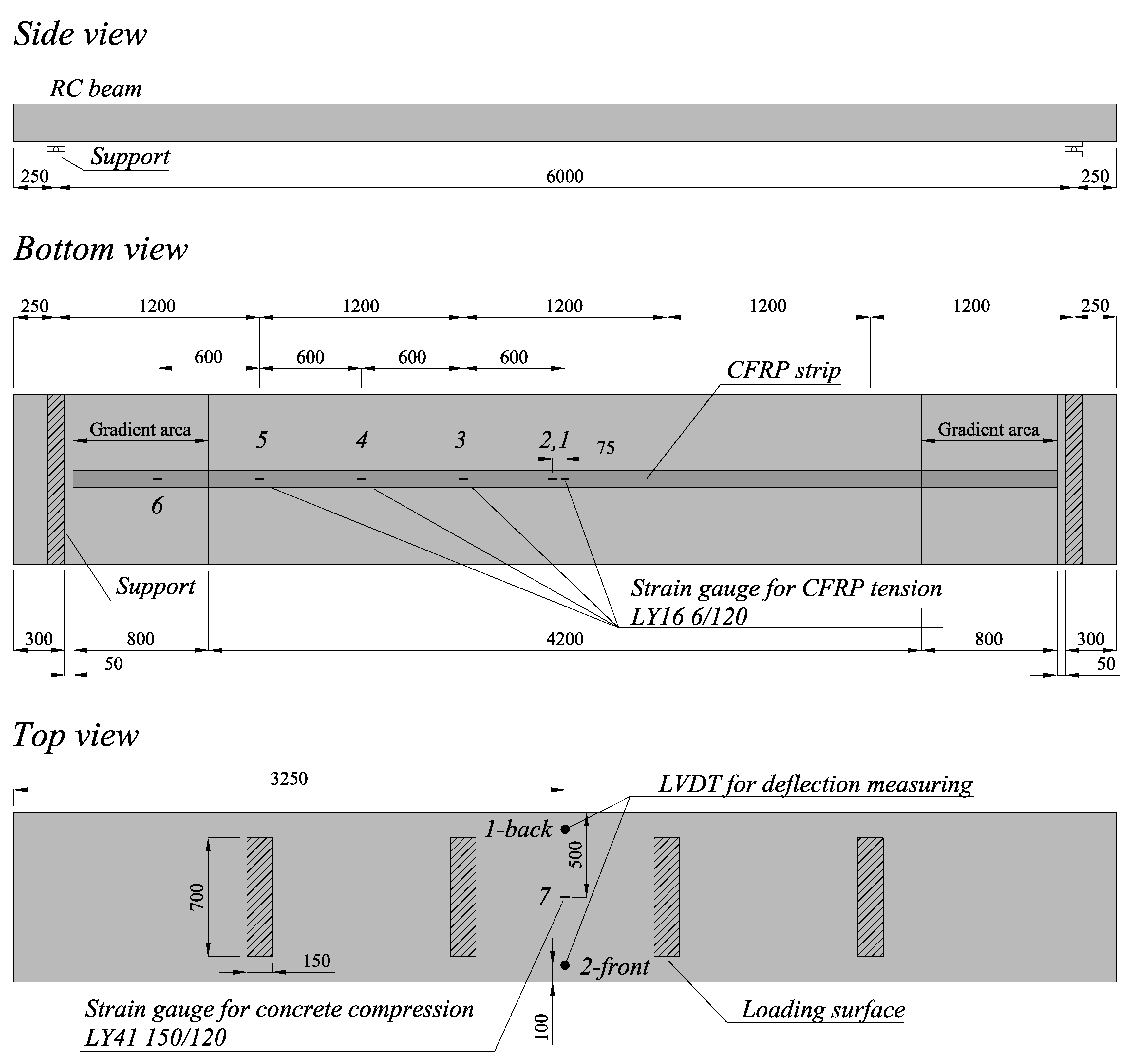
2.1. Beam Geometry and Materials


| Steel bar | Rp,0.2 (MPa) | Rm (MPa) |
|---|---|---|
| 1 | 524 | 601 |
| 2 | 551 | 631 |
| 3 | 532 | 609 |
| 4 | 553 | 637 |
| Average | 540 | 619 |
| Standard deviation | 14.6 | 17.2 |
| Beam | fcm,cube,28 (MPa) | fcm,cube,test (MPa) |
|---|---|---|
| 1 | 56.8 | 63.2 |
| 2 | 54.3 | 57.7 |
| 3 | 52.2 | 54.0 |
| 4 | 54.1 | 69.4 * |
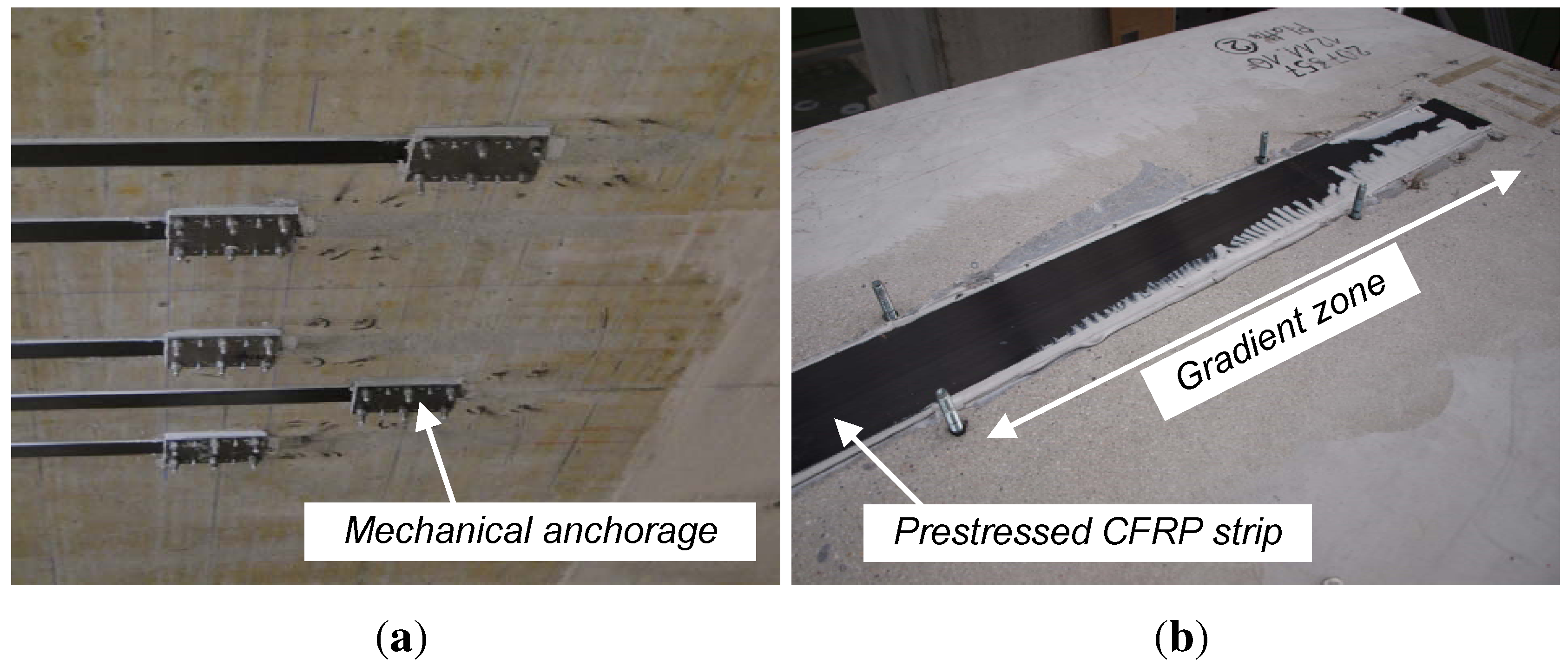
2.2. Retrofitting Characteristics and Procedure
| εf,p (-) | tf (mm) | bf (mm) | Comment | |
|---|---|---|---|---|
| Beam 1 | 0.59 | 1.2 | 100 | Strip applied regularly |
| Beam 2 | 0.59 | 1.2 | 100 | Strip end ground with sand paper |
| Beam 3 | 0.60 | 1.2 | 100 | Strip applied regularly |
| Beam 4 | 0.61 | 1.2 | 100 | Bottom surface for strengthening corresponds to the upper casting surface |
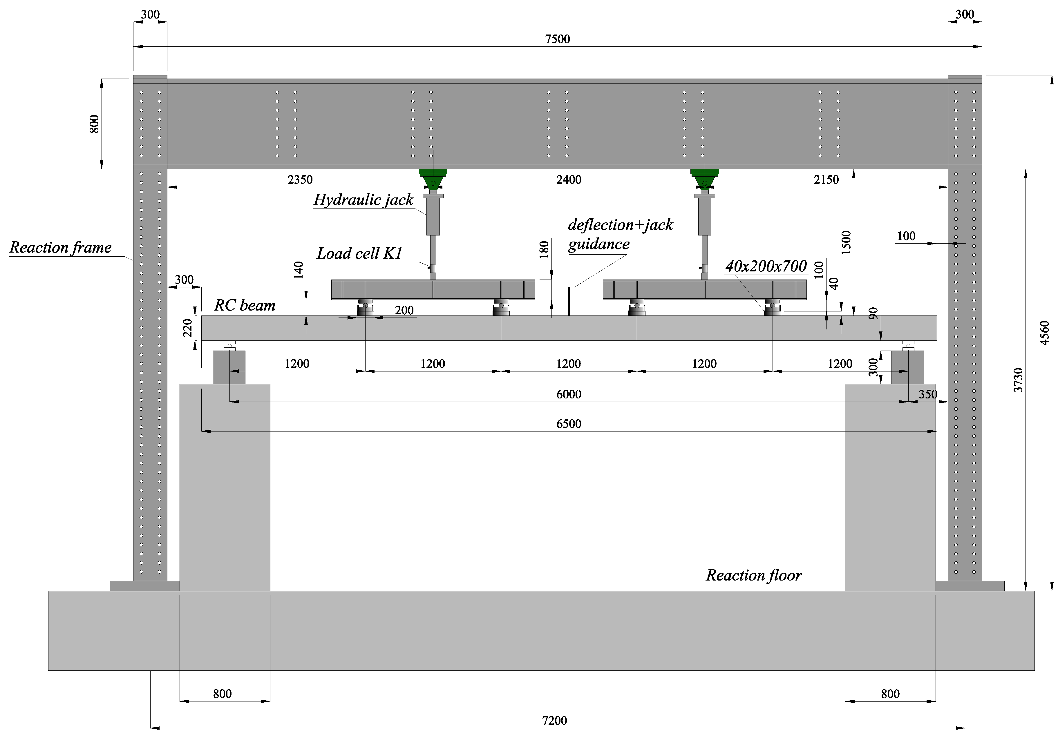
2.3. Test Setup and Program

3. Results and Discussion

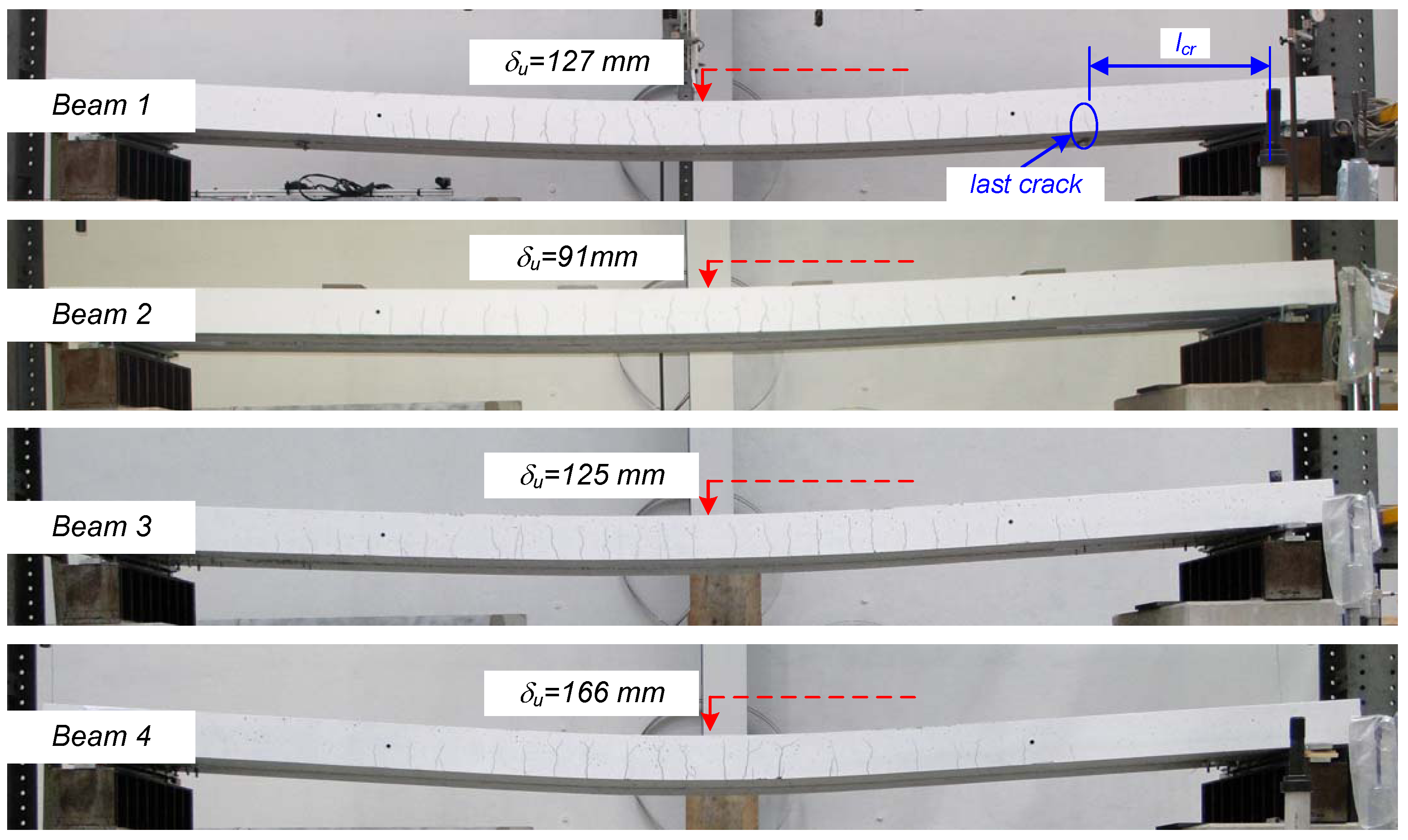
| Beam | Fcr | δcr | Fy | δy | Fu | δu | εf,u | Εc,u | Δεf [%] | lcr (m) |
|---|---|---|---|---|---|---|---|---|---|---|
| No. | (mm) | (mm) | (kN) | (mm) | (kN) | (mm) | (%) | (%) | (%) | (m) |
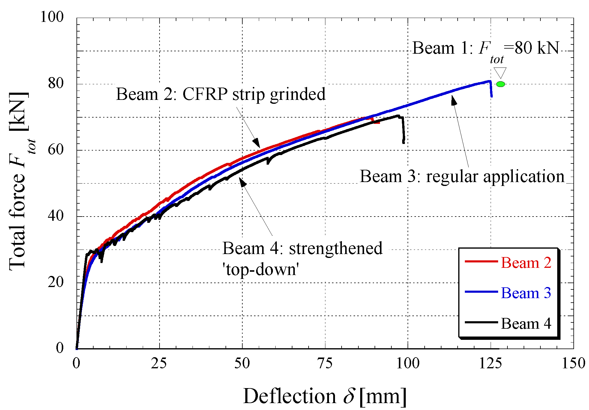
| 1 | * | * | * | * | ≈80 | 127.4 | 1.42 | 1.27 | 0.83 | 1.10 |
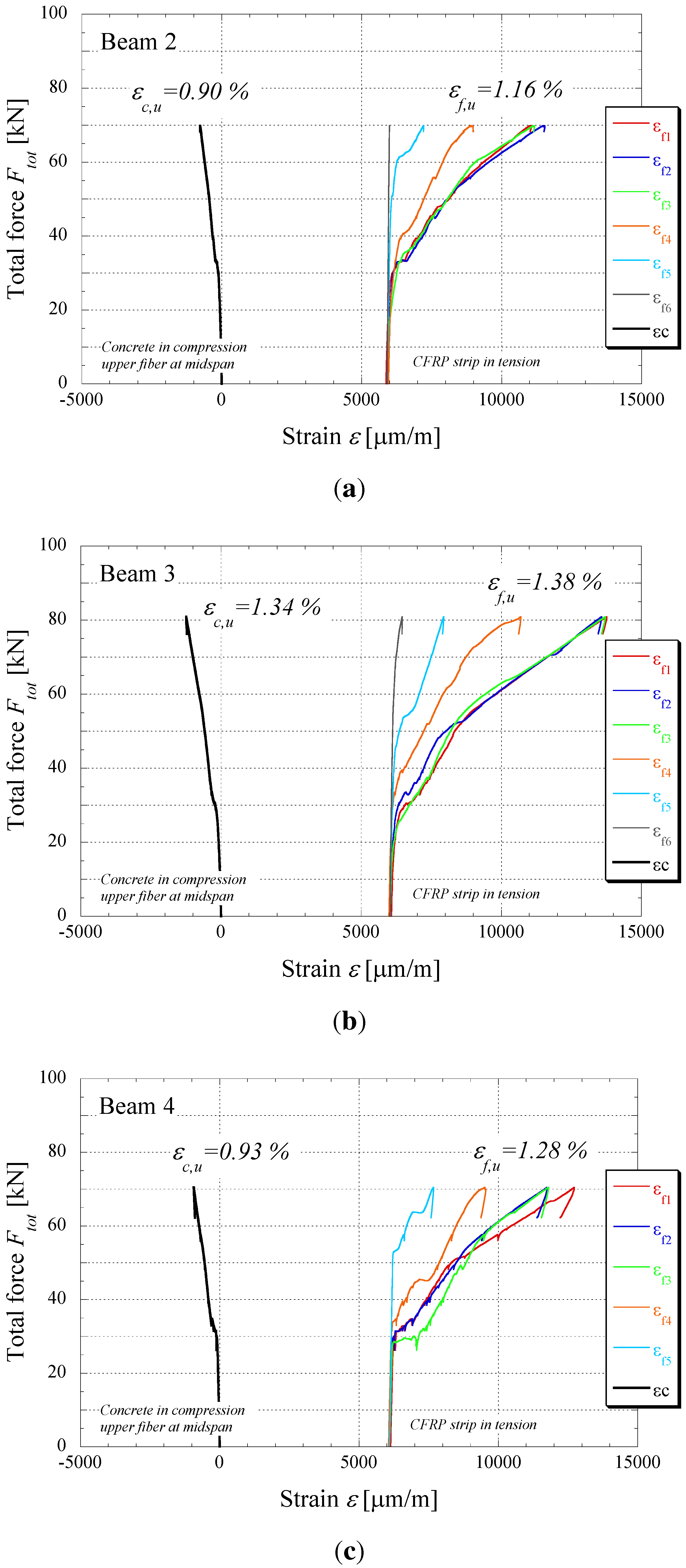
| 2 | 20 | 2.4 | 54 | 41 | 69.9 | 91.2 | 1.16 | 0.90 | 0.57 | 1.15 |
| 3 | 18 | 2.2 | 55 | 46 | 80.9 | 125.3 | 1.38 | 1.34 | 0.78 | 1.11 |
| 4 | 28 | 2.9 | 57 | 57 | 70.5 | 98.8 | 1.28 | 0.93 | 0.67 | 1.27 |

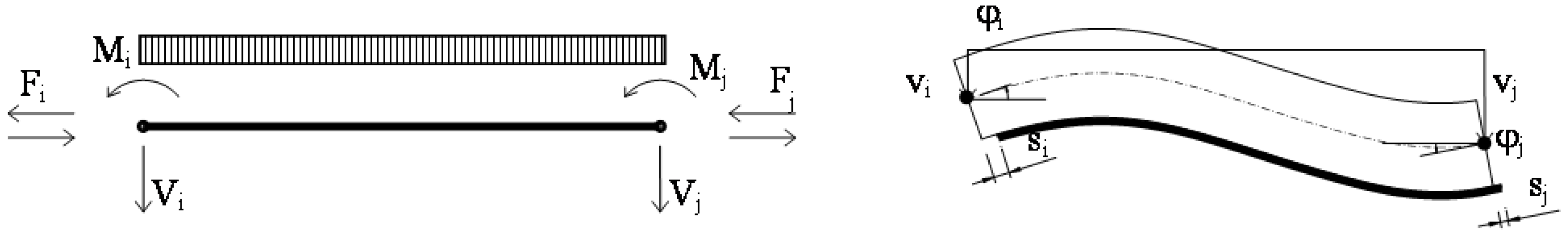
4. Numerical Code

 , which represents the axial strain imposed on the FRP strip for applying the prestressing action to the RC beam. Although mathematical details about the whole derivation of the contribution, Q0,p, corresponding to the pre-stressing action cannot be reported herein due to space constraints, it is easy to recognize that the final analytical expression of Q0 can be written as follows:

- The well-established rational law by Sargin is adopted for concrete in compression. All its relevant properties can be defined in terms of the compressive strength, fc, and an ultimate axial strain εcu = 0.0035 is assumed as a conventional value for the concrete crushing condition ([20]);
- A trilinear elastic-hardening-plastic law is adopted for reinforcing steel bars. It allows the simulation of the linear behavior up to yielding stress fy, a hardening branch up to the ultimate tensile strength, fs,u, which is kept constant up to a conventional value of the ultimate strain of εs,u = 0.06;
- A linear elastic behavior is assumed for the FRP strip in tension, depending on the elastic modulus, Ef, and the ultimate stress, ff,u.
- A bilinear elastic-softening bond-slip law is finally employed for describing the interaction between the FRP laminate and the concrete substrate ([10],
![Polymers 06 00114 i004]() = 8 MPa, sf,el = 0.02 mm, sf,u = 0.2 mm). The key parameters are mainly related to the fracture energy in mode II, Gf,II, and can be identified via pull-out tests on FRP strips glued onto concrete blocks.
= 8 MPa, sf,el = 0.02 mm, sf,u = 0.2 mm). The key parameters are mainly related to the fracture energy in mode II, Gf,II, and can be identified via pull-out tests on FRP strips glued onto concrete blocks.


5. Conclusions and Outlook
- Short-term static loading tests demonstrate the efficiency of the gradient anchorage. In the present case, the overall structural behavior is very satisfying, exhibiting a ductile deformation up to failure (ductility index μδ of 2.5).
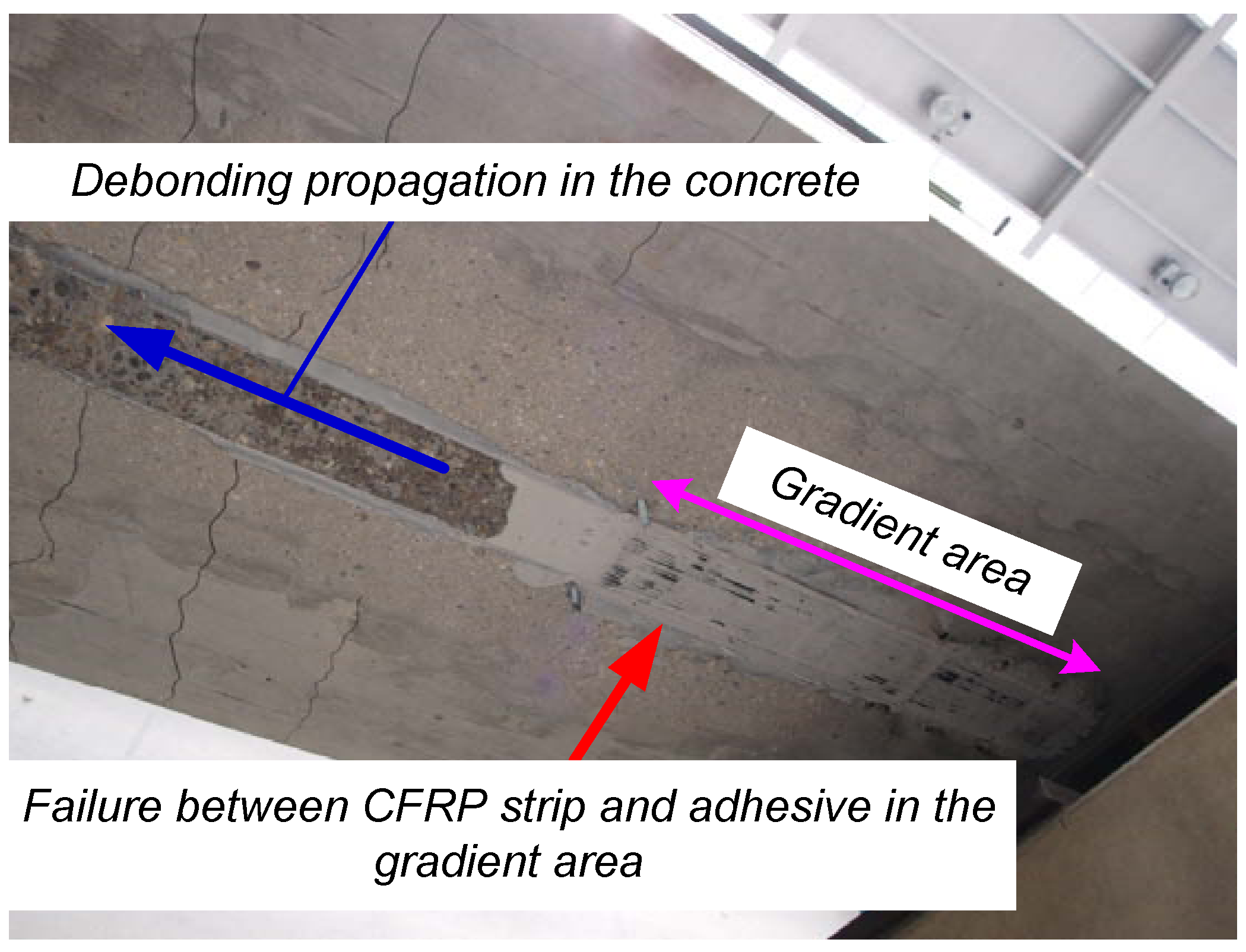
- Flexural cracks do not develop in the present case in the gradient anchorage zone, thus not creating any premature debonding in this region.
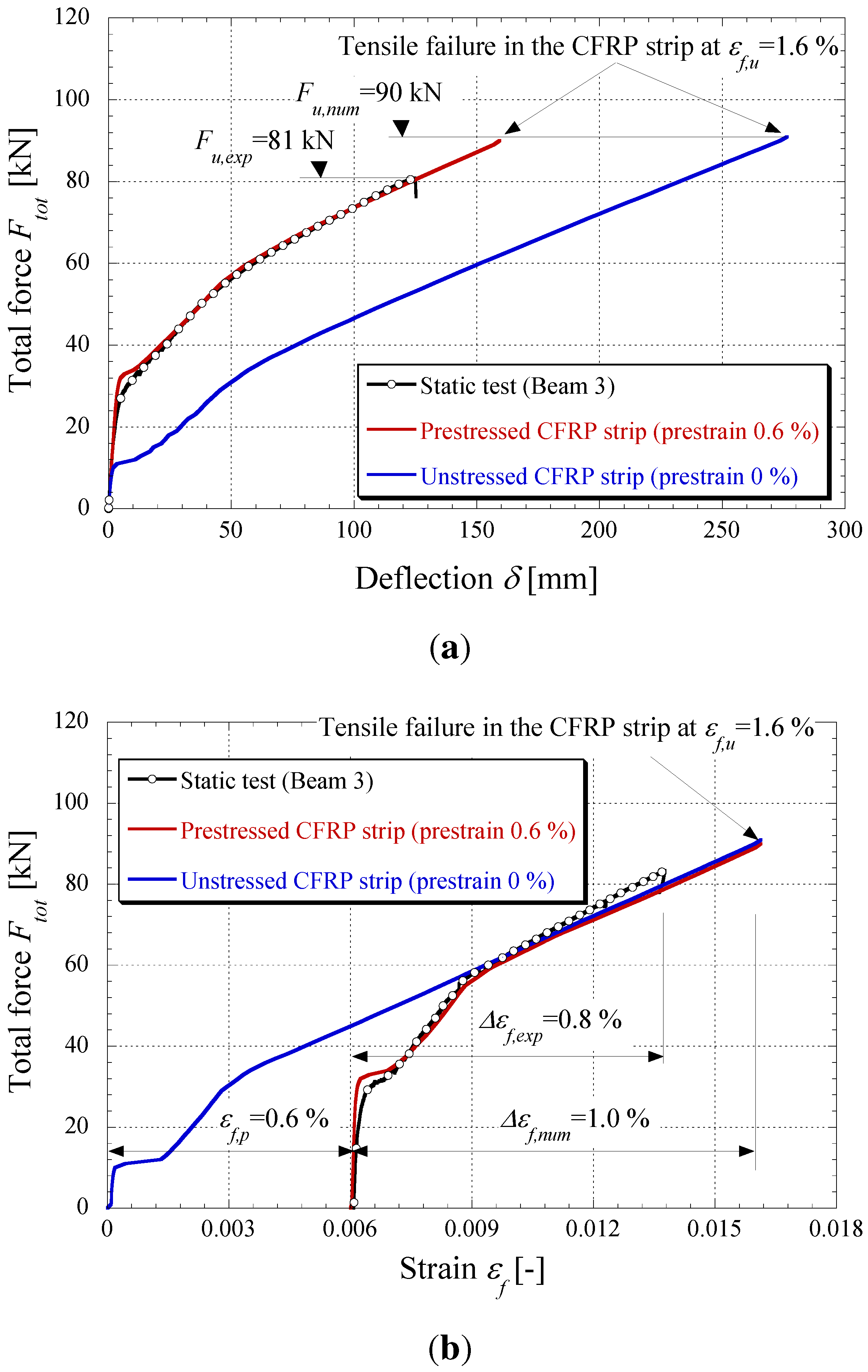
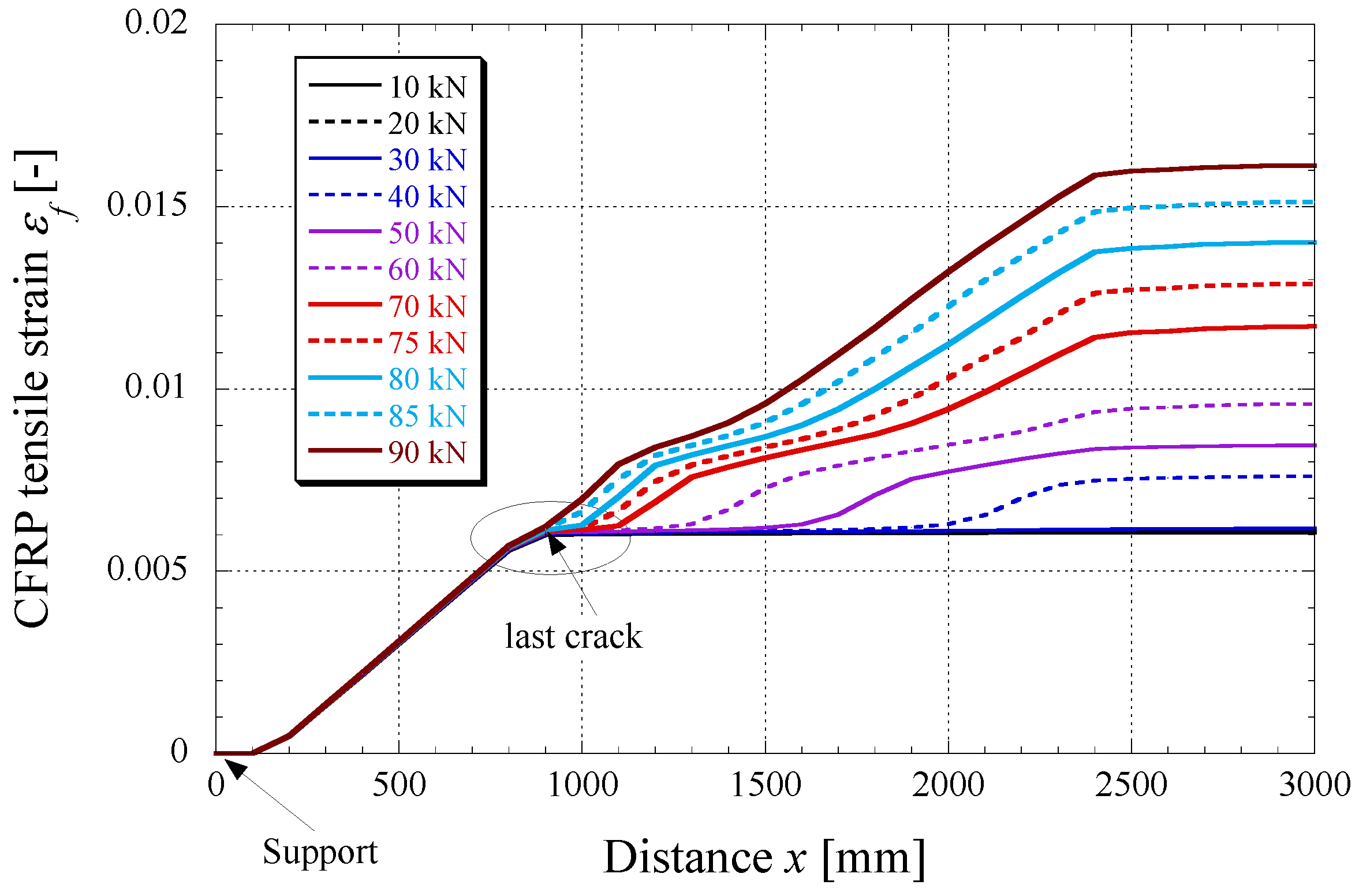
- The observed ultimate tensile strains at failure in the CFRP strips (1.4%) is very close to the ultimate strain of the material itself (1.6%). This clearly demonstrates the benefit of prestressing, allowing one to profit from the material’s excellent mechanical performances in tension in a much better way. An even higher degree of prestrain might eventually lead to the tensile failure of the strip. Initially unstressed strips bonded to concrete cannot develop such high strains under flexural loading; failure in this case always occurs due to debonding.
- The numerical code is able to reproduce the experiments with a very high degree of accuracy, despite a slight overestimation of the cracking load.
- For future numerical applications, more advanced failure criteria in terms of debonding design will be included in the finite element code.
Acknowledgements
Conflicts of Interest
References
- Meier, U. Strengthening of structures using carbon fibre/epoxy composites. Constr. Build. Mater. 1995, 9, 341–351. [Google Scholar] [CrossRef]
- Bakis, C.; Bank, L.; Brown, V.; Cosenza, E.; Davalos, J.; Lesko, J.; Machida, A.; Rizkalla, S.; Triantafillou, T. Fiber-reinforced polymer composites for construction—State-of-the-art review. J. Compos. Constr. 2002, 6, 73–87. [Google Scholar] [CrossRef]
- Meier, U.; Stöcklin, I.; Terrasi, G. Civil Engineers can Make Better Use of the Strength of Fibrous Materials. In Proceedings of the International Conference on Composites in Construction (CCC), Porto, Portugal, 10–12 October 2001.
- Pellegrino, C.; Modena, C. Flexural Strengthening of real-scale RC and PRC beams with end-anchored Pretensioned FRP laminates. ACI Struct. J. 2009, 106, 319–328. [Google Scholar]
- El-Hacha, R.; Wight, R.; Green, M. Innovative System for prestressing fiber-reinforced polymer Sheets. ACI Struct. J. 2003, 100, 305–313. [Google Scholar]
- El-Hacha, R.; Green, M.; Wight, R. Strengthening Concrete Structures with Prestressed FRP Systems. In Proceedings of the 4th International Conference on Construction Materials (CONMAT), Nagoya, Japan, 24–26 August 2009.
- França, P.; Costa, A. Behavior of Flexural Strengthened Beams with Prestressed CFRP Laminates. In Proceedings of the FRPRCS-8, Patras, Greece, 18 July 2007.
- Fernandes, P.; Sena-Cruz, J. Flexural Response of HSC Girders Strengthened with 2 Non- and Prestressed CFRP Laminates. In Proceedings of the FRPRCS-11, Guimaraes, Portugal, 26–28 June 2013.
- Stöcklin, I.; Meier, U. Strengthening of Concrete Structures with Prestressed and Gradually Anchored CFRP Strips. In Proceedings of the FRPRCS-5, Cambridge, UK, 6–18 July 2001.
- Czaderski, C.; Martinelli, E.; Michels, J.; Motavalli, M. Effect of curing conditions on strength development in an epoxy resin for structural strengthening. Compos. B Eng. 2012, 43, 398–410. [Google Scholar] [CrossRef]
- Czaderski, C. Strengthening of Reinforced Concrete Members by Prestressed Externally Bonded Reinforcement with Gradient Method. Ph.D. Thesis; ETH Zürich: Zürich, Switzerland, April 2012. Available online: http://www.dx.doi.org/10.3929/ethz-a-007569614.
- Michels, J.; Czaderski, C.; El-Hacha, R.; Brönnimann, R.; Motavalli, M. Temporary bond strength of partly cured epoxy adhesive for anchoring prestressed CFRP strips on concrete. Compos. Struct. 2012, 94, 2667–2676. [Google Scholar] [CrossRef]
- Michels, J.; Czaderski, C.; El-Hacha, R.; Brönnimann, R.; Motavalli, M. Partly Cured Epoxy Adhesive for Anchoring Prestressed CFRP Strips on Concrete. In Proceedings of the 3rd Asia-Pacific Conference on FRP in Structures (APFIS), Sapporo, Japan, 2–4 February 2012.
- Czaderski, C.; Motavalli, M. 40-Year-old full-scale concrete bridge girder strengthened with prestressed CFRP plates anchored using gradient method. Compos. B Eng. 2007, 38, 878–886. [Google Scholar] [CrossRef]
- Kotynia, R.; Walendziak, R.; Stöcklin, I.; Meier, U. RC slabs strengthened with prestressed and gradually anchored CFRP strips under monotonic and cyclic loading. J. Compos. Constr. (ASCE) 2011, 15, 168–180. [Google Scholar] [CrossRef]
- Motavalli, M.; Czaderski, C.; Pfyl-Lang, K. Prestressed CFRP for strengthening of reinforced concrete structures: Recent developments at Empa, Switzerland. J. Compos. Construct. (ASCE) 2011, 15, 194–205. [Google Scholar] [CrossRef]
- Michels, J.; Czaderski, C.; Brönnimann, R.; Motavalli, M. Gradient Anchorage Method for Prestressed CFRP Strips-Principle and Application. In Proceedings of the Bridge Maintenance, Safety, Management, Resilience and Sustainability-Proceedings of the Sixth International Conference on Bridge Maintenance, Safety and Management, Safety, Management, 8–12 July 2012; pp. 1981–1986.
- Michels, J.; Cruz, J.S.; Czaderski, C.; Motavalli, M. Structural strengthening with prestressed CFRP strips anchored with the gradient method. J. Compos. Construc. (ASCE) 2013, 17, 651–661. [Google Scholar] [CrossRef]
- Michels, J.; Czaderski, C.; Martinelli, E.; Motavalli, M. RC Beams Strengthened with Prestressed and Gradually Anchored CFRP Strips. In Proceedings of the Second Middle East Conference on Smart Monitoring, Assessment and Retrofitting of Structures (SMAR), Istanbul, Turkey, 9–11 September 2013.
- Fédéation internationale du béton. Structural Concrete—Textbook on Behaviour, Design and Performance: Updated Knowledge of the CEB/FIP Model Code (1990); FIB - Féd. Int. du Bton: Lausanne, Switzerland, 1999. [Google Scholar]
- S&P-Clever-Reinforcement-Company-AG. Qualitätsprüfzeugnis 052641 IG CFK 150/2000 S100/1.2 / Charge:706032; S&P Clever Reinforcement Company AG: Seewen, Switzerland, 2011. [Google Scholar]
- S&P-Clever-Reinforcement-Company-AG. S&P Resin 220 Epoxy Adhesive - Technical Data Sheet; S&P Clever Reinforcement Company AG: Seewen, Switzerland, 2012. [Google Scholar]
- Subramaniam, K.; Carloni, C.; Nobile, L. Width effect in the interface fracture during shear debonding of FRP sheets from concrete. Eng. Fract. Mech. 2007, 74, 1241–1249. [Google Scholar]
- Oudah, F.; El-Hacha, R. A new ductility model of reinforced concrete beams strengthened using fiber reinforced polymer reinforcement. Compos. B Eng. 2012, 43, 3338–3347. [Google Scholar] [CrossRef]
- Faella, C.; Martinelli, E.; Nigro, E. Formulation and validation of a theoretical model for intermediate debonding in FRP strengthened RC beams. Compos. B Eng. 2008, 39, 645–655. [Google Scholar] [CrossRef]
- Martinelli, E.; Faella, C.; di Palma, G. Shear-flexible steel-concrete composite beams in partial interaction: Closed form “exact” expression of the stiffness matrix. J. Eng. Mech. (ASCE) 2012, 138, 151–163. [Google Scholar] [CrossRef]
- Martinelli, E.; Napoli, A.; Nunziata, B.; Realfonzo, R. A 1D finite element model for the flexural behaviour of RC beams strengthened with MF-FRP strips. Compos. Struct. 2014, 107, 190–204. [Google Scholar] [CrossRef]
- Harmanci, Y. Prestressed CFRP for Structural Retrofitting-Experimental and Analytical Investigation. Master’s Thesis, ETH Zurich, Zürich, Switzerland, 2013. [Google Scholar]
© 2014 by the authors; licensee MDPI, Basel, Switzerland. This article is an open access article distributed under the terms and conditions of the Creative Commons Attribution license (http://creativecommons.org/licenses/by/3.0/).
Share and Cite
Michels, J.; Martinelli, E.; Czaderski, C.; Motavalli, M. Prestressed CFRP Strips with Gradient Anchorage for Structural Concrete Retrofitting: Experiments and Numerical Modeling. Polymers 2014, 6, 114-131. https://doi.org/10.3390/polym6010114
Michels J, Martinelli E, Czaderski C, Motavalli M. Prestressed CFRP Strips with Gradient Anchorage for Structural Concrete Retrofitting: Experiments and Numerical Modeling. Polymers. 2014; 6(1):114-131. https://doi.org/10.3390/polym6010114
Chicago/Turabian StyleMichels, Julien, Enzo Martinelli, Christoph Czaderski, and Masoud Motavalli. 2014. "Prestressed CFRP Strips with Gradient Anchorage for Structural Concrete Retrofitting: Experiments and Numerical Modeling" Polymers 6, no. 1: 114-131. https://doi.org/10.3390/polym6010114