Mechanical Behavior of BFRP-Steel Composite Plate under Axial Tension

School of Civil Engineering, Dalian University of Technology, Dalian 116024, China
*
Author to whom correspondence should be addressed.
Polymers 2014, 6(6), 1862-1876; https://doi.org/10.3390/polym6061862
Submission received: 8 April 2014
/
Revised: 28 May 2014
/
Accepted: 12 June 2014
/
Published: 23 June 2014
(This article belongs to the Special Issue Fiber-Reinforced Polymer Composites in Structural Engineering)
Abstract
:Combining the advantages of basalt fiber-reinforced polymer (BFRP) material and steel material, a novel BFRP-steel composite plate (BSP) is proposed, where a steel plate is sandwiched between two outer BFRP laminates. The main purpose of this research is to investigate the mechanical behavior of the proposed BSP under uniaxial tension and cyclic tension. Four groups of BSP specimens with four different BFRP layers and one control group of steel plate specimens were prepared. A uniaxial tensile test and a cyclic tensile test were conducted to determine the initial elastic modulus, postyield stiffness, yield strength, ultimate bearing capacity and residual deformation. Test results indicated that the stress-strain curve of the BSP specimen was bilinear prior to the fracture of the outer BFRP, and the BSP specimen had stable postyield stiffness and small residual deformation after the yielding of the inner steel plate. The postyield modulus of BSP specimens increased almost linearly with the increasing number of outer BFRP layers, as well as the ultimate bearing capacity. Moreover, the predicted results from the selected models under both monotonic tension and cyclic tension were in good agreement with the experimental data.
1. Introduction
Structural applications of fiber-reinforced polymer (FRP) composites have been attractive in the civil engineering community, due to their superior material properties, such as high specific stiffness, high specific strength and substantial resistance to corrosion and fatigue [1,2,3,4]. Design codes or guides for FRP-reinforced structures have been issued in many countries [5,6,7,8]. However, the applications of FRP are limited due to the main shortcomings of FRP as follows: (1) low elastic modulus, especially for glass fiber-reinforced polymer (GFRP), aramid fiber-reinforced polymer (AFRP) and basalt fiber-reinforced polymer (BFRP), which means that the stiffness of the FRP-reinforced structures is relatively low and the performance of structures can be negatively affected during the service stage; (2) poor ductility, which means ideal ductility and high seismic performance cannot be achieved in FRP-reinforced structures; (3) high initial cost, which means that the FRP material cannot meet the requirements of low cost for the structural material; (4) low strength utilization rate in the structural application; and (5) poor shear capacity [9,10].
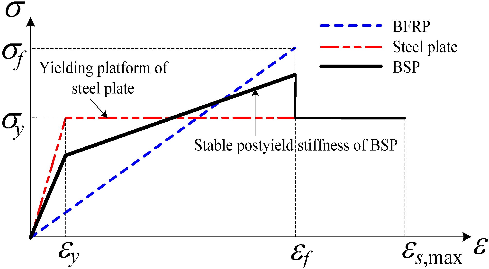
Steel material has a high elastic modulus, good ductility, low cost, a high strength utilization rate and good shear capacity, which could make up for the shortcomings of the FRP mentioned above. Combining the advantages of FRP and steel, a new composite material is expected to have outstanding comprehensive properties, such as a high elastic modulus, good ductility, relative low cost, high tensile and shear strength and high corrosion resistance [11,12]. Based on this idea, Wu et al. [12] had developed a steel-FRP composite bar (SFCB) that is compounded by an inner ribbed steel bar and outer longitudinal FRP in a pultrusion process. Due to the good properties of high temperature resistance, good environmental protection, low cost and other common properties of FRP, BFRP as a newly developed composite material has been gradually applied in civil engineering recently. In this paper, a novel BFRP-steel composite plate (BSP) based on the same idea mentioned above is proposed, in which a steel plate is sandwiched between two outer BFRP laminates. As shown in Figure 1, BSP is composed of linear elastic BFRP and elastic-plastic steel with stable postyield stiffness (stiffness after yield). Therefore, postyield stiffness can be achieved when BSP was used as the structural material. Existing research indicated that a certain postyield stiffness of concrete structures could effectively reduce post-earthquake residual deformation, which could ensure good reparability [13,14]. Based on the novel BSP, new damage-controllable structures with good reparability can be developed, and performance-based seismic designs can be implemented more easily.
Figure 1.
Stress-strain relationship of the basalt fiber-reinforced polymer (BFRP)-steel composite plate (BSP).
Figure 1.
Stress-strain relationship of the basalt fiber-reinforced polymer (BFRP)-steel composite plate (BSP).

According to the proposed BSP, a uniaxial tensile test and a cyclic tensile test were conducted to determine the BSP’s initial elastic modulus, postyield stiffness, yield strength, ultimate strength, ultimate bearing capacity, unloading stiffness and residual deformation. The theoretical stress-strain relationship models for BSP under uniaxial tension and cyclic tension were selected and analyzed.
In this paper, the objective of the present work is to: (1) investigate the mechanical behavior of the proposed BSP under uniaxial tension and cyclic tension; and (2) verify whether the selected theoretical models could precisely predict the mechanical behavior of the proposed BSP under uniaxial tension and cyclic tension.
2. Experimental Program
2.1. Material Properties and Manufacture of BFRP-Steel Composite Plate (BSP) Specimens
Unidirectional basalt fiber fabric with a thickness of 0.115 mm and an areal density of 300 g/m2, which was produced by the Sichuan Aerospace Tuoxin Basalt Industrial Co. Ltd of China, was used to produce BSP. A mild steel plate with a thickness of 3.05 mm was applied as the inner steel plate. Adhesive (JGN-T) provided by the Dalian Kaihua New Technology Engineering Co. Ltd of China was chosen. The basic mechanical properties of each material are shown in Table 1.

| Type of material | Elastic modulus (GPa) | Yield strength (MPa) | Tensile strength (MPa) | Elongation (%) |
|---|---|---|---|---|
| Basalt fiber fabric | 91 | – | 2350 | 2.6 |
| Steel plate | 190 | 435 | – | 20 |
| Adhesive | 2.7 | – | 48 | 2.7 |
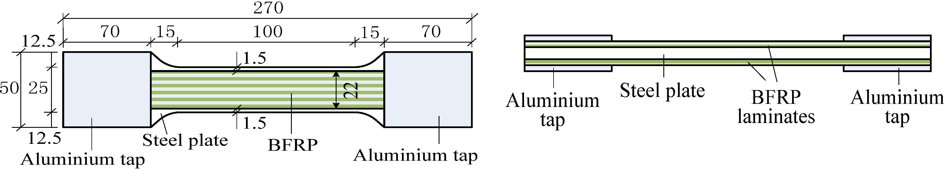
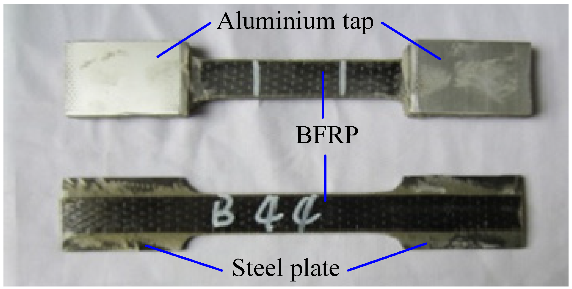
The dimensions and the shape of the steel plate strip for BSP specimens were configured according to the Chinese test standard of GB/T 228.1-2010 [15] and the steel plate strip is sandwiched between two outer BFRP laminates, as shown in Figure 2. It should be noted that the width of the steel plate strip in the test zone is 25 mm, while the BFRP is 22 mm. As a trial test, all specimens have been fabricated by a hand lay-up process at present. In future production, the specimens would be fabricated by pultrusion or a Resin Transfer Molding (RTM) process. To manufacture BSP specimens with ideal performance, the interface behavior between the inner steel plate and the outer BFRP should be guaranteed, which is of vital importance to the mechanical properties of BSP. Based on numerous trials of surface treatment, the following steps were chosen to ensure the bonding behavior between the inner steel plate and the outside BFRP: (1) removing the grease, rust and dirt from the surface of the steel plate and coarsening the surface of the steel plate with a grinder; and (2) cleaning the surface with acetone. After the surface treatment, adhesive was brushed onto the surface of steel plate, and then the fabric strips were bonded on both sides of the steel plate (shown in Figure 2). To improve the performance of BSP specimens, basalt fiber fabric strips were applied on the steel plate with a certain tensioning force, which could make the fabric strips straight along the fiber direction to eliminate their initial flexure. Meanwhile, a certain pressure with 2 kg of iron was applied during the curing process of BFRP laminates. The method of dealing with the manufacturing of the BSP specimen was suitable for handmade products and proved to be excellent in a series of trials. Finally, aluminum taps were attached to both ends of the BSP specimens to prevent the premature fracture of the BFRP from gripping pressure during the tests. Figure 3 shows a photo of the BSP specimens.
Figure 2.
Diagram of the BSP specimen (units in mm).

Figure 3.
BSP specimens with and without aluminum tabs.

2.2. Specimen Design
In order to investigate the tensile behavior of the newly proposed BSP, a uniaxial tensile test and a cyclic tensile test were conducted. In the uniaxial tensile test, 15 specimens of 5 types were prepared and tested, including one control type of steel plate (SP) and four types of BSP with four different BFRP layers, as shown in Table 2. Each type of BSP specimen was given a name, which was started with the abbreviation, BSP, followed by a number representing the total number of BFRP layers bonded onto the steel plate. For example, the specimen BSP2 represents that two layers of BFRP were bonded on both sides of steel plate, respectively. There were 3 analogous specimens of each type. The name of each specimen of the same type was identified by adding another number to the type name, for instance BSP2-X (X = 1, 2, 3). The thickness of the BFRP laminates, including the adhesive could not be controlled accurately, due to the limitations of the hand layup process. Therefore, the average thicknesses of the three specimens of each type were taken and presented in Table 2.
| Type | Thickness of steel plate (mm) | Number of BFRP Layers | Total thickness of the specimen (mm) |
|---|---|---|---|
| SP | 3.05 | 0 | 3.05 |
| BSP2 | 3.05 | 2 | 3.85 |
| BSP4 | 3.05 | 4 | 4.46 |
| BSP6 | 3.05 | 6 | 4.85 |
| BSP8 | 3.05 | 8 | 5.32 |
In the cyclic tensile test, 5 specimens were prepared and tested, including one type of control steel plate and four different types of BSP, which were the same as those of the uniaxial tensile specimens, as listed in Table 2. However, in the cyclic tensile test, there was only one specimen of each type.
2.3. Testing Setup and Loading Program
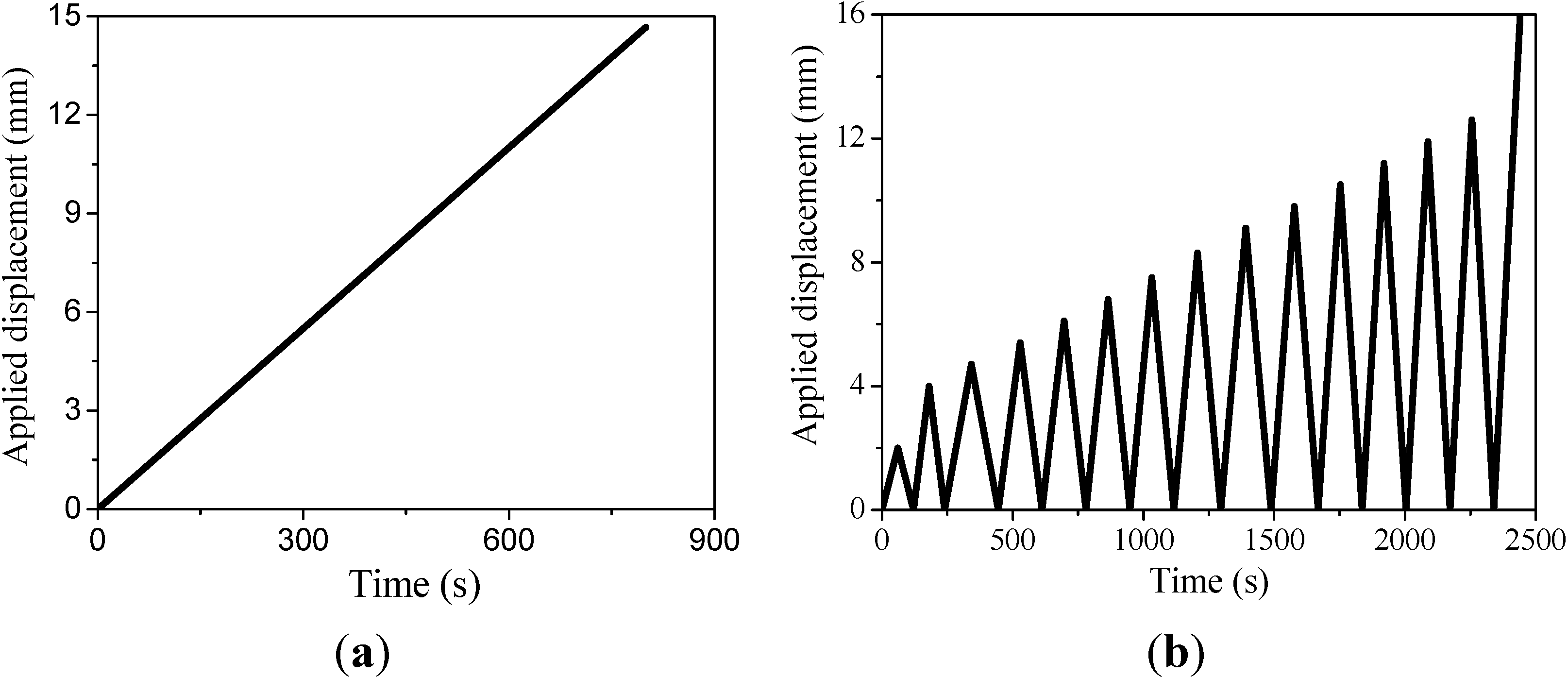
Both the uniaxial tensile test and cyclic tensile test were performed on a universal testing machine by displacement control. The strain data were collected from the extensometer before BFRP rupture and calculated from the stroke displacements of the testing machine after BFRP rupture. Loading programs for the two tests were shown in Figure 4. For the uniaxial tensile test, the displacement was increased monotonically with a speed of 1 mm/min until the test specimen failed. According to the Chinese test standard of GB/T 228.1-2010 [15], a loading speed of 1 mm/min was chosen. For the cyclic tensile test, a single-cyclic load was applied with the gradually increasing displacement amplitude; while the loading and unloading speed was 1 mm/min until the test specimen failed.
Figure 4.
Loading programs of (a) the uniaxial tensile test and (b) the cyclic tensile test.

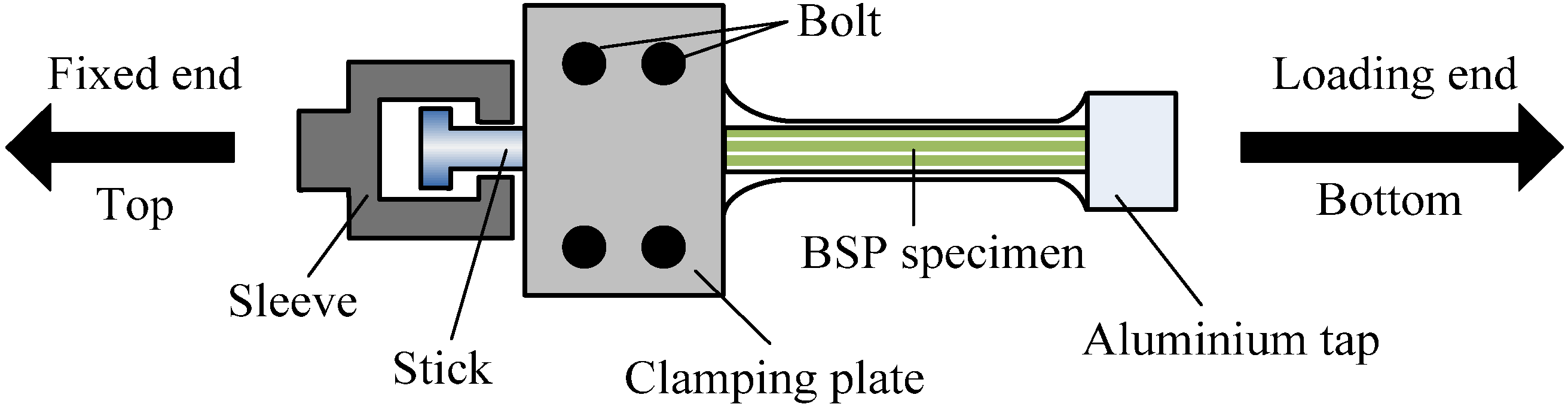
It is necessary to design an additional clamping apparatus, which can avoid the compression buckling of BSP during unloading in the cyclic loading test due to the plastic strain in the BSP specimen after the yielding of the inner steel plate. As shown in Figure 5, the steel clamping apparatus includes a sleeve, a stick and clamping plates. Additionally, the stick can move freely in the sleeve. The top end of the clamping apparatus was fixed, while the bottom end of the specimen was left free. Thus, the top of the BSP specimen was a compression-free end and only experienced tension during the cyclic tensile loading. When the tensile load of the specimen decreased to 0, the stick could separate from the bottom of the sleeve.
Figure 5.
Diagram of the clamping apparatus for the cyclic tensile test.

3. Uniaxial Tensile Behaviors of BSP
3.1. Test Results
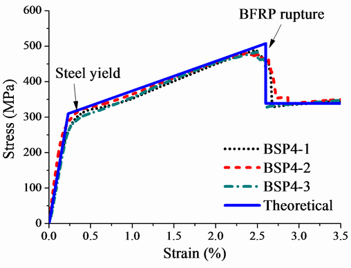
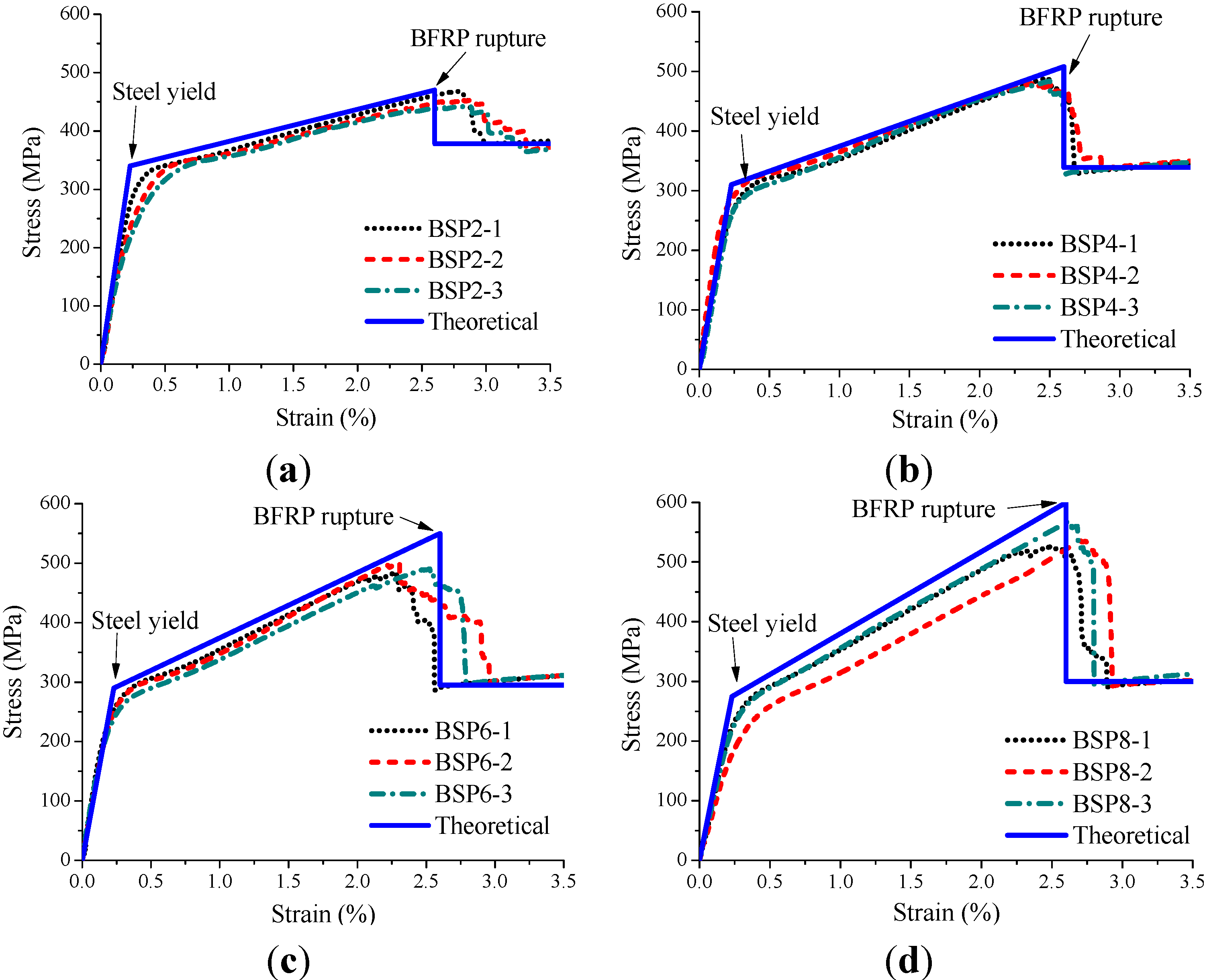
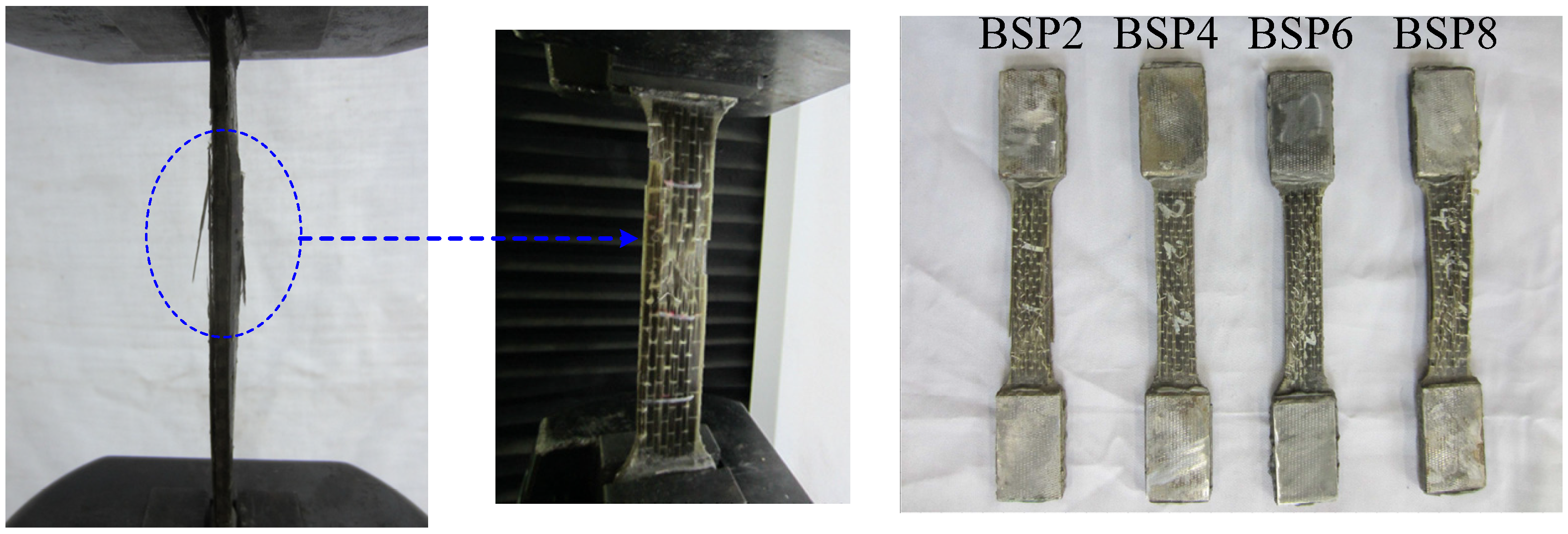
The uniaxial tensile test results of each BSP type are shown in Figure 6, Table 3 and Table 4, where: EI is the initial elastic modulus; EII is the postyield modulus; fbsy is the strength at yielding of the inner steel plate; fbsu is the ultimate strength; and Nu is the ultimate bearing capacity. The test results in Table 3 and Table 4 are the average values of three specimens for each type. The stress-strain curves of the uniaxial tensile test are shown in Figure 6. In the initial loading, the load was shared by the inner steel plate and the outside BFRP. When the tensile strain reached about 0.23%, there was an inflection point in the curves, which indicated that the inner steel plate of the BSP had yielded. After the steel plate reached the yield point, the stress would increase less, but stably with the same increment, which meant that the BSP would have a stable stiffness. The load was mainly undertaken by the outside of the BFRP, because the steel plate could not bear more loading after its yielding. As the load increased, the bearing capacity of BSP reached its limitation, and the outer BFRP fractured in the middle zone along the length of the specimen and, later, had a jump. After that, the load was undertaken only by the inner steel plate, and the residual bearing capacity of the BSP specimen remained fairly constant. The BSP specimen showed a beneficial failure mode, in which the steel plate yielded firstly, followed by the outside BFRP fracturing secondly, and finally, the steel plate would reach tensile failure in the region near the fractured BFRP. No obvious delamination of the BSP samples was observed during the loading process. Figure 7 showed the typical final failure, which was a threadlike fracture. All of the failures occurred in the middle zone along the length of the specimens, which indicated that the two gripping ends were safe.
Figure 6.
Stress-strain curves of BSP under uniaxial tension: (a) BSP2; (b) BSP4; (c) BSP6; and (d) BSP8.
Figure 6.
Stress-strain curves of BSP under uniaxial tension: (a) BSP2; (b) BSP4; (c) BSP6; and (d) BSP8.

| Type | EI (GPa) | EII (GPa) | ||||
|---|---|---|---|---|---|---|
| Exp. a | Theo. b | R.E. c | Exp. a | Theo. b | R.E. c | |
| BSP2 | 134.2 | 155.3 | 15.7% | 4.5 | 4.7 | 4.4% |
| BSP4 | 130.7 | 138.2 | 5.7% | 8.1 | 8.2 | 1.2% |
| BSP6 | 126.2 | 130.2 | 3.2% | 11.1 | 11.4 | 2.7% |
| BSP8 | 117.4 | 122.8 | 4.6% | 13.5 | 13.9 | 3.0% |
Note: a Experimental values; b Theoretical calculation values; c Relative error.
| Type | fbsy (MPa) | fbsu (MPa) | Nu (kN) | ||||
|---|---|---|---|---|---|---|---|
| Exp. a | Theo. b | R.E. c | Exp. a | Theo. b | R.E. c | ||
| BSP2 | 309.4 | 355.6 | 14.9% | 455.2 | 468.9 | 3.0% | 43.8 |
| BSP4 | 293.0 | 316.4 | 8.0% | 483.8 | 512.2 | 5.9% | 53.9 |
| BSP6 | 275.6 | 300.3 | 9.0% | 492.0 | 570.9 | 16.0% | 59.6 |
| BSP8 | 258.6 | 281.1 | 8.7% | 551.2 | 609.4 | 10.6% | 73.3 |
Note: a Experimental values; b Theoretical calculation values; c Relative error.
Figure 7.
Typical failure of a BSP specimen.

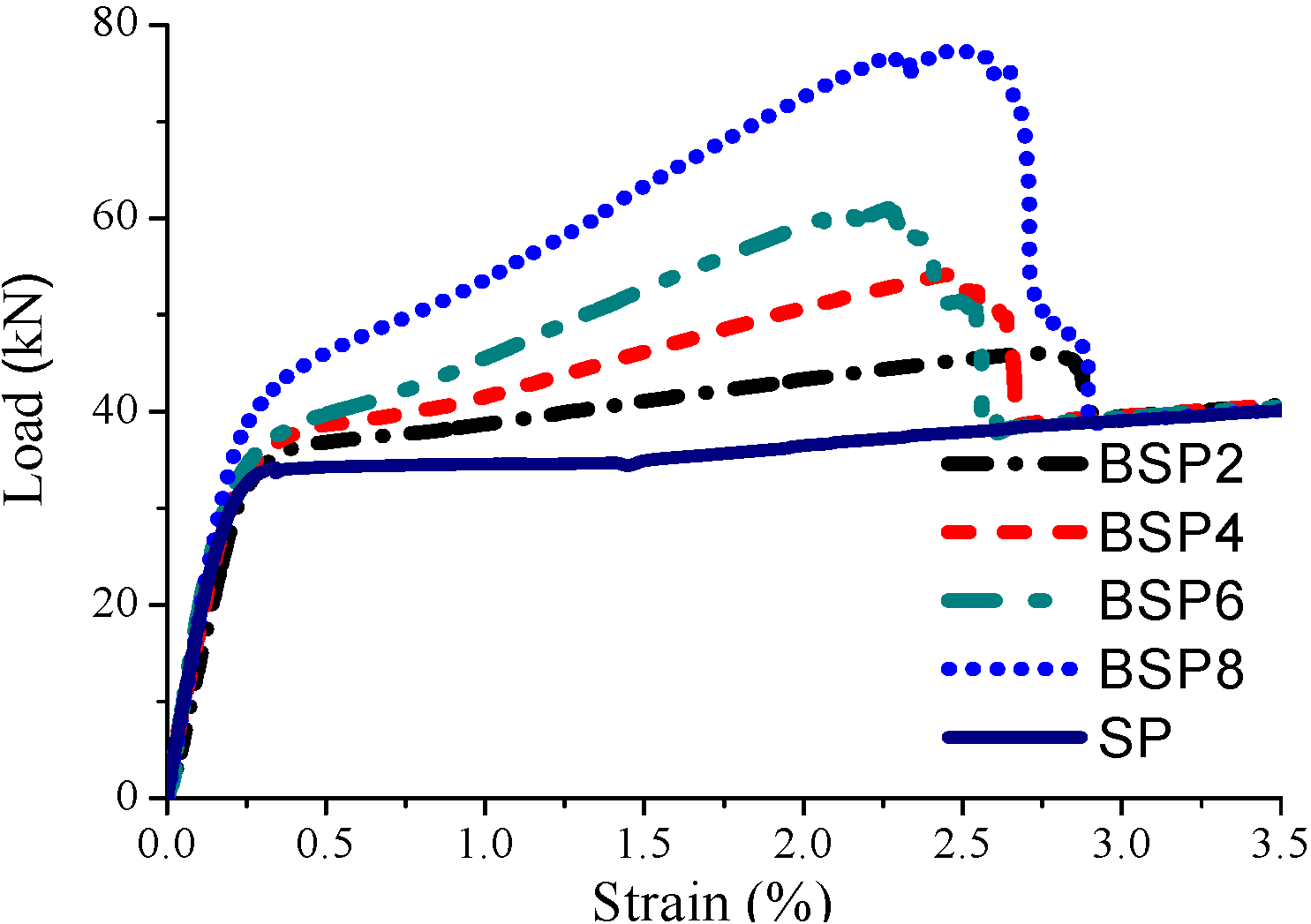
Figure 8 compares the load-strain curves of BSP specimens and the SP specimen. It can be seen from Figure 8 that the load-strain curves of all BSP specimens were bilinear before BFRP fracture, and the curves after BFRP fracture presented the residual steel plate intrinsic ductility with its yield load. Figure 9 shows how the numbers of BFRP layers affect the postyield modulus EII and the ultimate bearing capacity Nu for BSP specimens. It can be seen that the postyield modulus and ultimate bearing capacity increase almost linearly with the increasing numbers of BFRP layers, respectively.
Figure 8.
Load-strain curves comparing BSP specimens and the SP specimen.

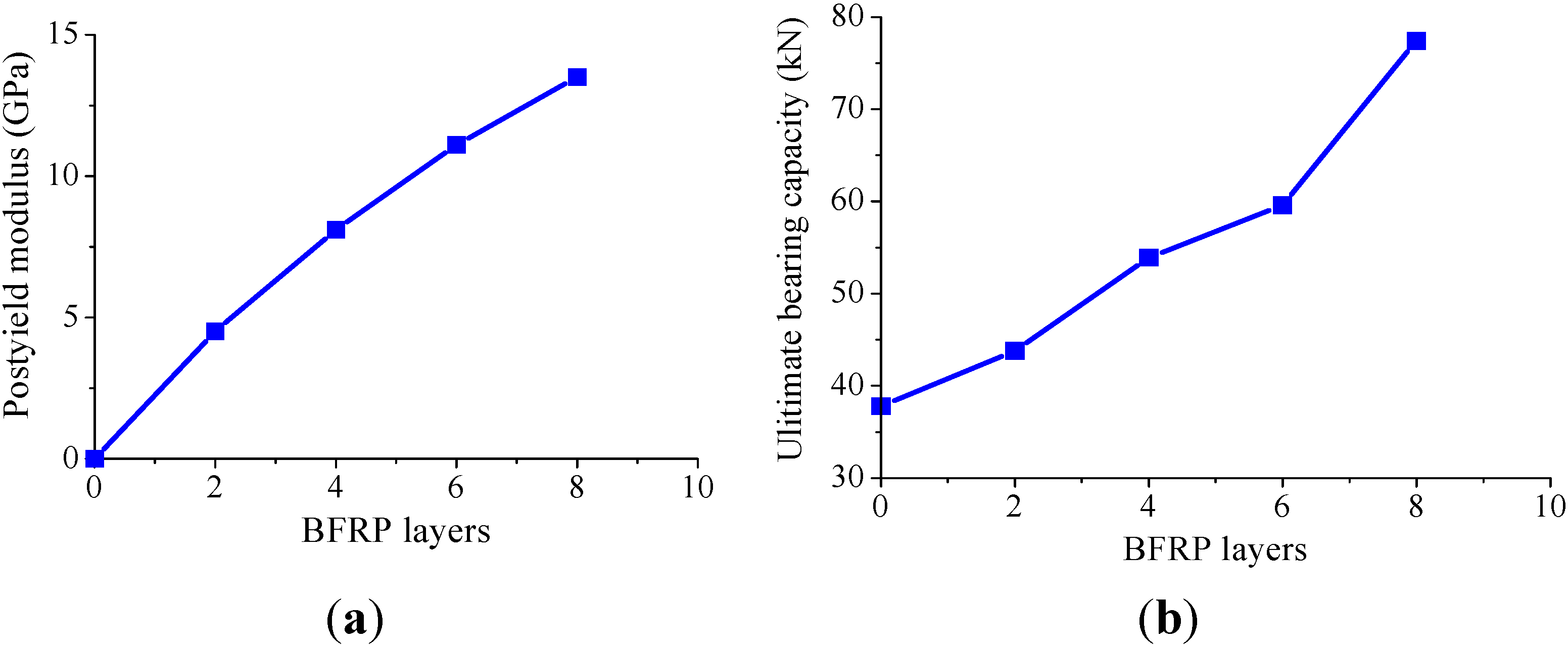
Figure 9.
The effect of the number of BFRP layers on (a) the postyield modulus and (b) the ultimate bearing capacity.
Figure 9.
The effect of the number of BFRP layers on (a) the postyield modulus and (b) the ultimate bearing capacity.

3.2. Theoretical Model of the Stress-Strain Relationship for BSP
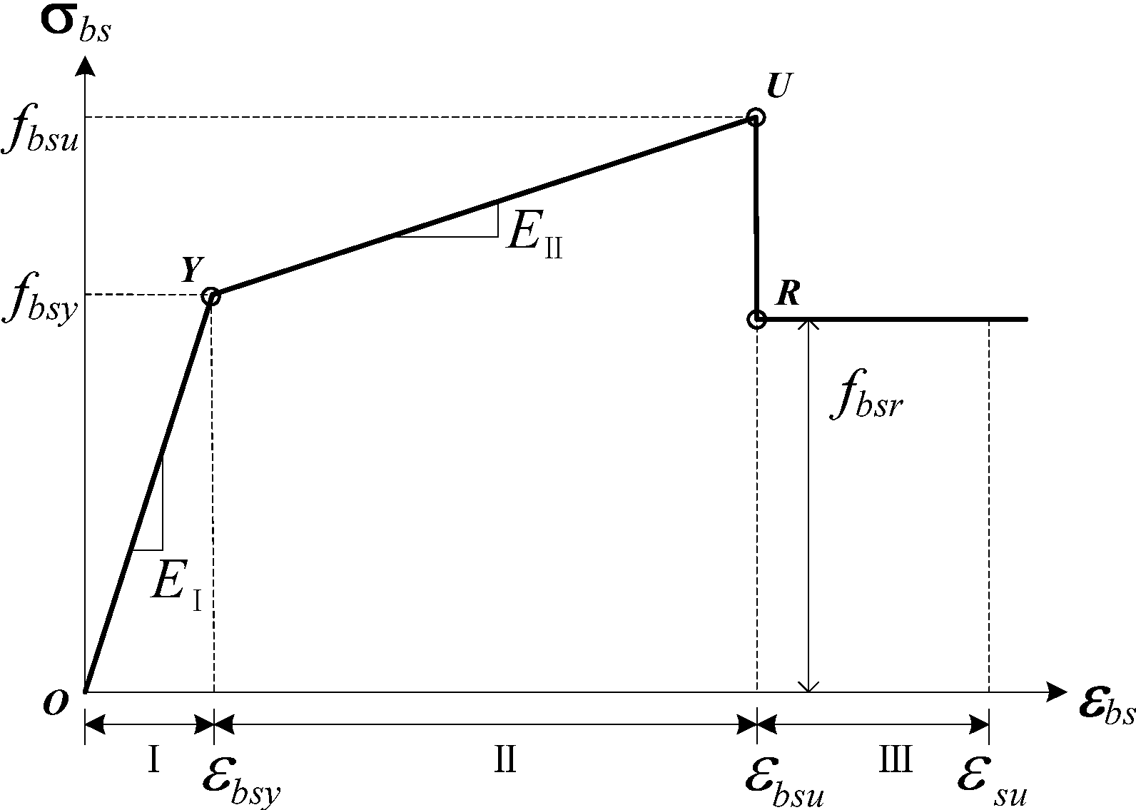
Supposing that interface bonding is ideal, that deformation between the outer FRP and inner steel is harmonious and using the mixture rule, Wu et al. [12] presented a theoretical model of the stress–strain relationship of a steel-FRP composite bar (SFCB) under a uniaxial load, which could be obtained from the properties of the steel and FRP. The BSP proposed in this paper is similar to SFCB, because both of them are composed of inner steel and outer FRP. Therefore, the model presented by Wu et al. [12] was accepted for the theoretical calculation of the stress-strain relationship for BSP. Depending on the model, the total strain was divided into three intervals, which are shown in Figure 10. The strain Interval I was from zero to the strain when the steel plate yielded. The equations for the tensile stress σI and elastic modulus EI are as follows:
where Es, As and εy are the elastic modulus, the cross-section area and the yield strain of the inner steel plate, respectively; Ebf and Abf are the elastic modulus and cross-section area of the outside basalt fiber fabric, respectively; A is the total cross-section area of BSP; and A = As + Abf + Aa, where Aa is the cross-section area of the adhesive, where the elastic modulus and strength are neglected in the theoretical calculation.
σI = ε(EsAs + EbfAbf) / A, 0 ≤ ε ≤ εy
EI = (EsAs + EbfAbf) / A, 0 ≤ ε ≤ εy
Figure 10.
The stress-strain relationship of BSP.

The strain Interval II is from the yielding strain of steel plate to the fracture strain of the outside basalt fiber fabric. The equations for the tensile stress σII and elastic modulus EII are as follows:
where fy is the yield stress of the steel plate and εbfu is the fracture strain of the outside basalt fiber fabric.
σII = (fyAs + εEbfAbf) / A, εy < ε ≤ εbfu
EII = (EbfAbf) / A, εy < ε ≤ εbfu
The strain Interval III is from the fracture strain of the outside basalt fiber fabric to the tensile failure strain of the steel plate. The stiffening effect of the steel is ignored in this theoretical calculation, and the equations for tensile stress σIII and the elastic modulus EIII are as follows (to coincide with the study, the cross-section area of BSP was chosen in calculating its stress, though the outside basalt fiber fabric has fractured):
where εsu is the tensile failure strain of the steel plate.
σIII = fsAs / A, εbfu < ε ≤ εsu
EIII = 0, εbfu < ε ≤ εsu
Based on the above theory, the stress-strain relationship of BSP can be written as follows:
![Polymers 06 01862 i001]() where σbs and εbs are the stress and strain of BSP, respectively; fbsy and εbsy are the yield strength and strain of BSP, respectively; fbsu and εbsu are the ultimate strength and strain of BSP when the outside BFRP fractured, respectively; for BSP as a whole, EI = fbsy/εbsy, EII = (fbsu − fbsy)/(εbsu − εbsy), which are numerically equivalent to Equations (2) and (4); fbsr is the residual strength of BSP; and fbsy, fbsu and fbsr can be obtained by substituting εy, εbfu and εsu into Equations (1), (3) and (5).
where σbs and εbs are the stress and strain of BSP, respectively; fbsy and εbsy are the yield strength and strain of BSP, respectively; fbsu and εbsu are the ultimate strength and strain of BSP when the outside BFRP fractured, respectively; for BSP as a whole, EI = fbsy/εbsy, EII = (fbsu − fbsy)/(εbsu − εbsy), which are numerically equivalent to Equations (2) and (4); fbsr is the residual strength of BSP; and fbsy, fbsu and fbsr can be obtained by substituting εy, εbfu and εsu into Equations (1), (3) and (5).

The test values and theoretical calculation values were compared, and the results are shown in Table 3 and Table 4. Meanwhile, the stress-strain curves obtained by the test and by theoretical calculation were compared, as shown in Figure 6. The comparison results show that there are low errors between the test data and the calculation values, and most of the relative errors between them are within 10%. The errors may result from the assumption that there is no initial flexure of the basalt fiber and no slip on the interface between the BFRP and the steel plate. In reality, there was a little bit of initial flexure of the basalt fiber in the hand layup process, and relative slip might occur after the yielding of the inner steel, especially when BSP experienced a large plastic deformation. In addition, a layer-by-layer failure would occur in BFRP laminates, especially for specimen BSP8 with the thick BFRP, which would reduce the ultimate bearing capacity.
4. Cyclic Tensile Behaviors of BSP
4.1. Test Results
Figure 11 shows the stress-strain curves of BSP specimens under cyclic tensile loading. It can be seen from Figure 11 that the tensile capacity of BSP had no obvious weakening effects during cyclic tensile loading. In the initial phase (small strain) after the yielding of BSP, the unloading curves of BSP approximately overlapped the reloading curves. With the development of plastic strain after yielding, the unloading stiffness of BSP decreased gradually, and the reloading curves no longer overlapped the unloading curves. Nevertheless, the reloading curve could still pass through the previous last peak points, which formed a closed hysteretic loop with the unloading curve.
Figure 11.
Stress-strain curves of BSP specimens under cyclic tensile loading: (a) BSP2; (b) BSP4; (c) BSP6; (d) BSP8; and (e) SP.
Figure 11.
Stress-strain curves of BSP specimens under cyclic tensile loading: (a) BSP2; (b) BSP4; (c) BSP6; (d) BSP8; and (e) SP.

The theoretical stress-strain curve of monotonic tensile loading was also shown in Figure 11 to compare with the test skeleton curve. It can be seen that the test skeleton curve was consistent with the theoretical curve, which indicated that the cyclic tensile times had no negative effect on the strength and stiffness of BSP. However, there was little difference between the theoretical curve and the test skeleton curve for the same reason as in uniaxial tensile test mentioned in Section 3.2. It should be noted that there are different inclinations of the upper part of the theoretical and experimental curves of the steel plate specimen. The theoretical one is horizontal, while the experimental one is upward and inclined. The reason is that the theoretical one was based on an ideal elastic-plastic model, while the experimental one was affected by the tensile stiffening effect, which was ignored in the theoretical model.
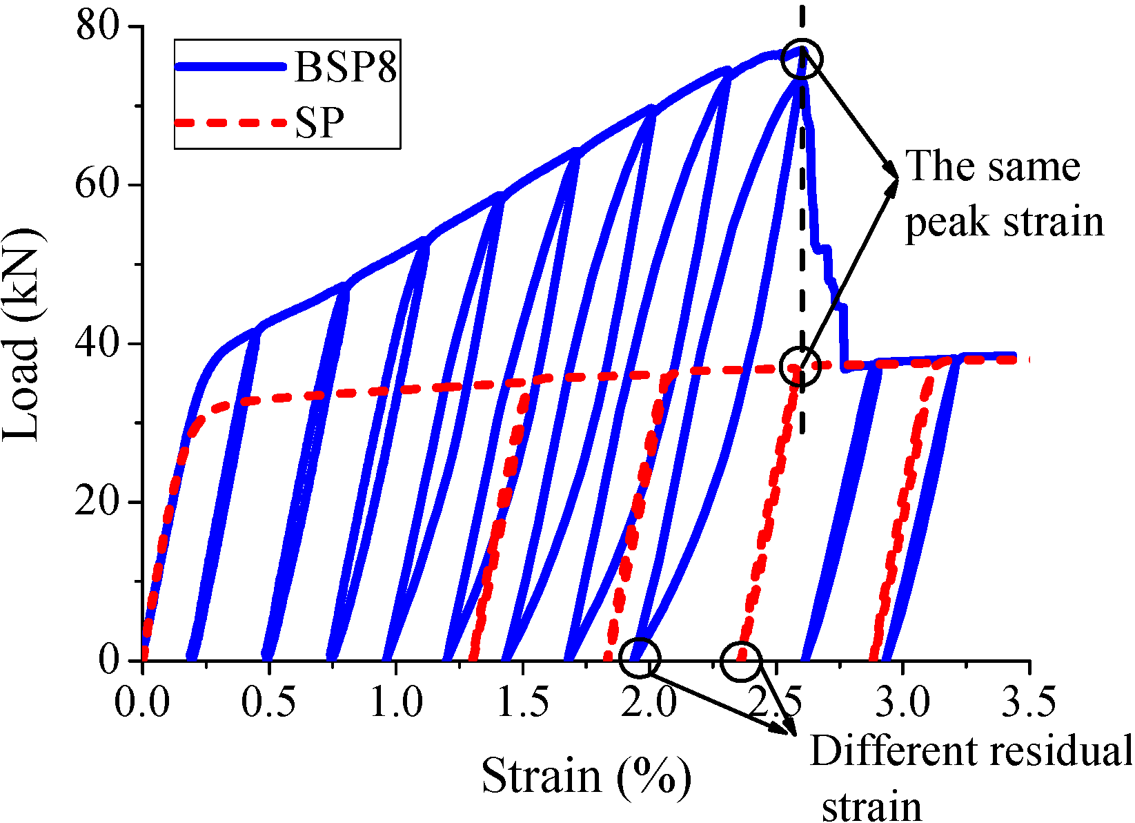
Figure 12 compares the residual strain of BSP with that of SP. As can be seen from the figure, the residual strain of BSP was obviously less than that of SP if they were unloaded from the same peak strain after yielding. For example, unloading from the peak strain of 2.61%, the residual strain of SP was 2.36% and that of BSP was 1.95%, which was 82% of the former. Because the residual strain of BSP being less than that of SP, it could be concluded that the structure reinforced with BSP could provide better reparability than that with SP.
Figure 12.
Comparison of the test values between BSP and SP under cyclic tensile loading.

4.2. Stress–Strain Relationship of BSP under Cyclic Tensile Loading
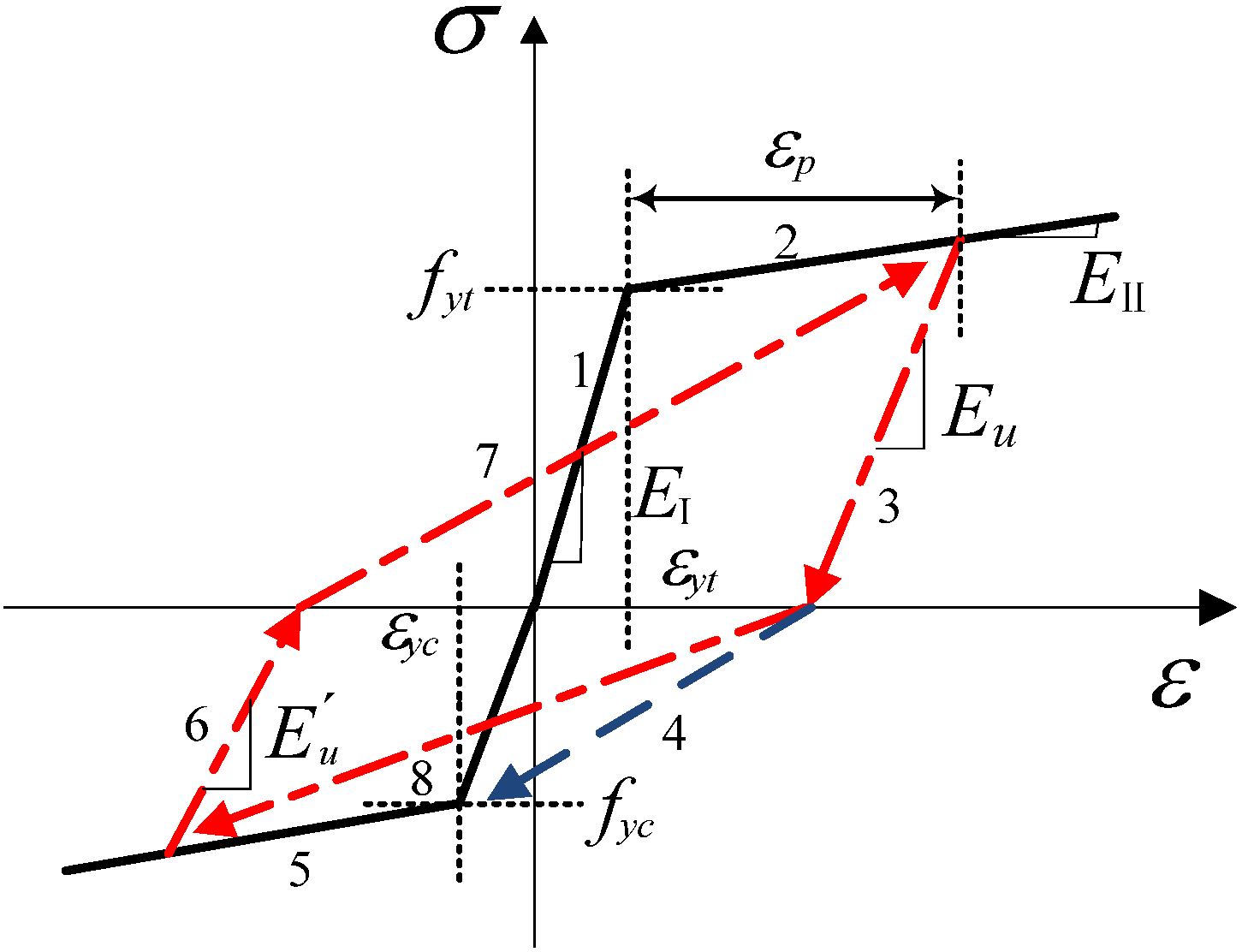
As a new reinforcing material of BSP for seismic structures in our study, it is necessary to investigate the stress-strain relationship of BSP under cyclic tensile loading. Based on the characteristics of the stress-strain curves from the cyclic tensile test, Wu et al. [12] presented the stress-strain restoring force model for their proposed steel-FRP composite bar (SFCB). The model presented by Wu et al. [12] was accepted for the theoretical calculation of the stress-strain relationship of BSP under cyclic tensile loading for the same reason mentioned in Section 3.2 of this paper, as shown in Figure 13. fyt is the tensile yield strength. fyc is the compressive yield strength. εyt is the tensile yield strain. εyc is the compressive yield strain. εp (εp = ε − εyt) is the plastic strain after the yielding of the inner steel plate of BSP. Eu is the unloading modulus. The equation for the unloading modulus Eu is:
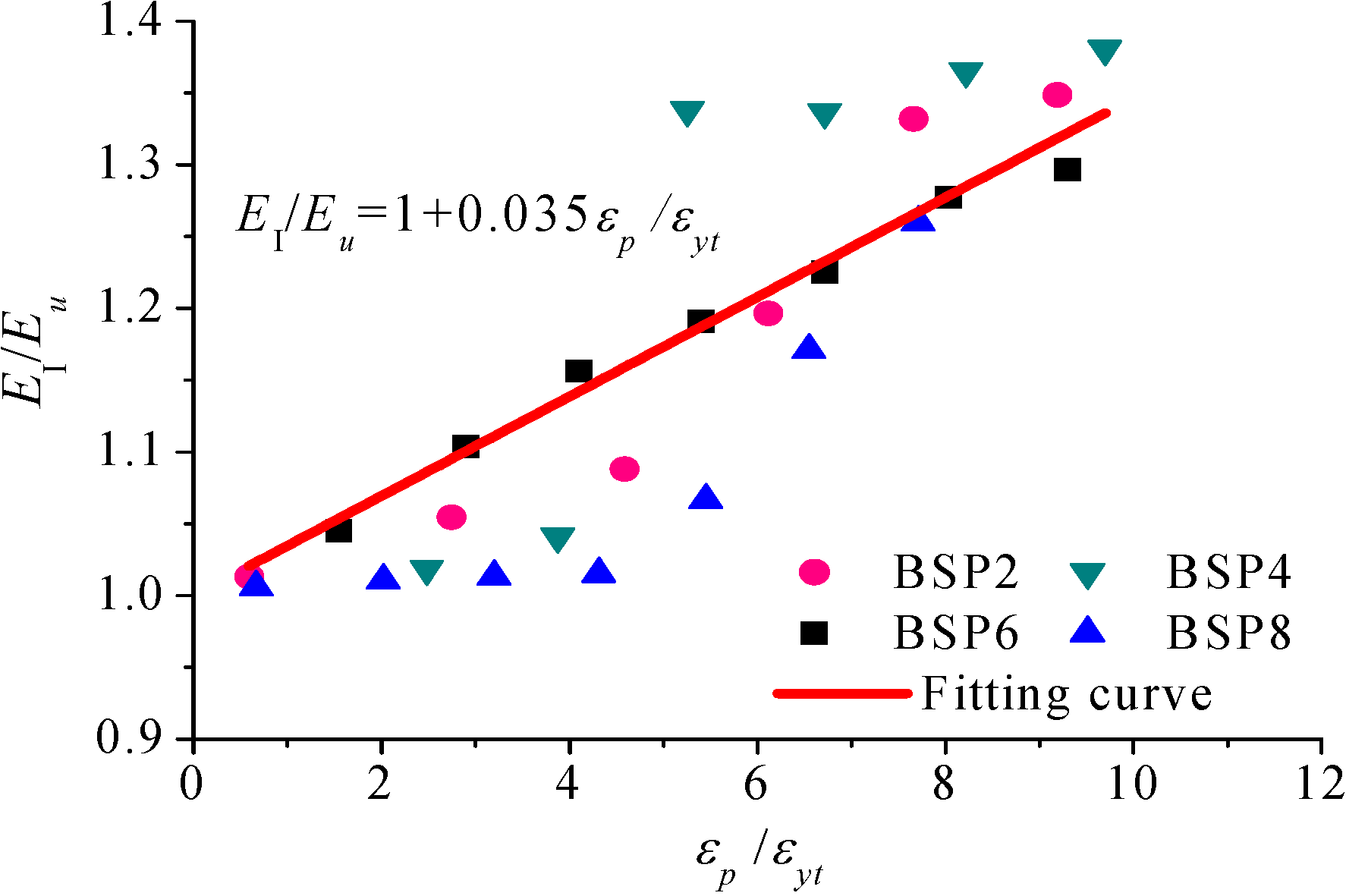
![Polymers 06 01862 i002]() where γ (γ ≥ 0) is the degradation coefficient of stiffness. Based on the tested stress-strain curves of the four different BSP specimens under cyclic tensile loading in Figure 11, the degradation rule of the unloading modulus is shown in Figure 14. By regression of the test data, γ is 0.035.
where γ (γ ≥ 0) is the degradation coefficient of stiffness. Based on the tested stress-strain curves of the four different BSP specimens under cyclic tensile loading in Figure 11, the degradation rule of the unloading modulus is shown in Figure 14. By regression of the test data, γ is 0.035.

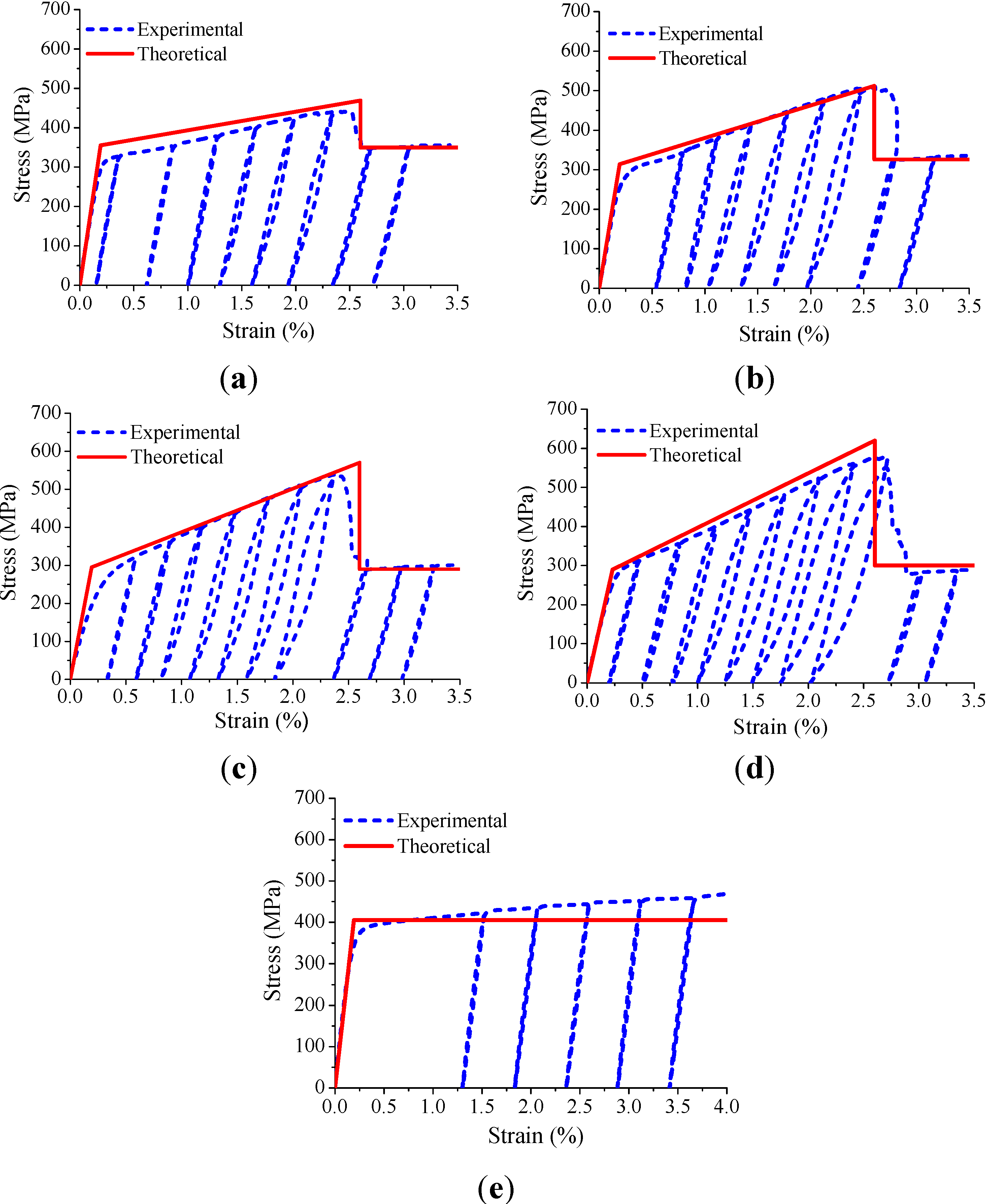
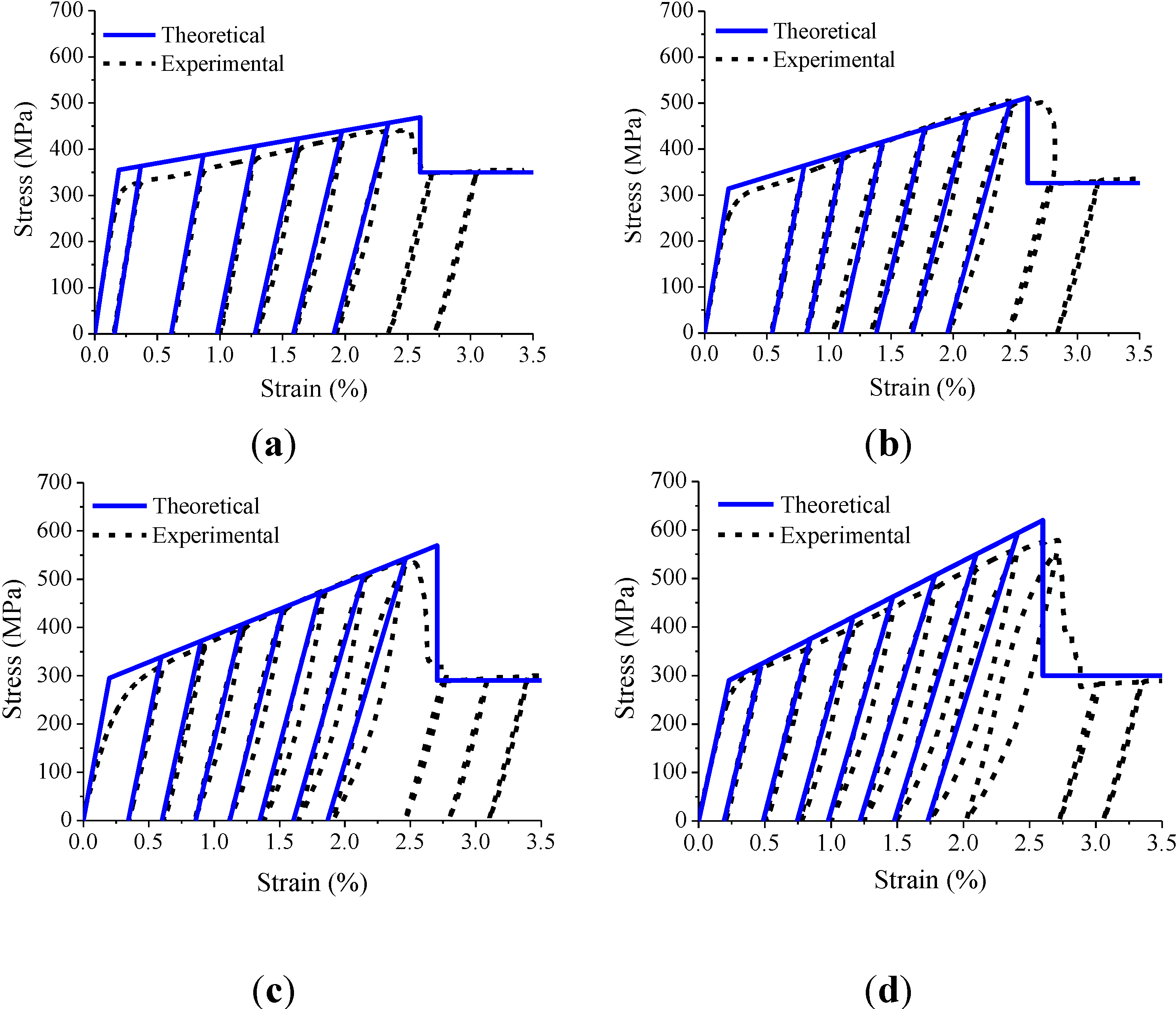
Based on the selected stress-strain relationship model, the regression unloading modulus was calculated, while Figure 15 compares the theoretical curves with the test curves for the BSP specimens under cyclic tensile loading. These comparisons showed that the degradation rule of the unloading modulus after the yielding of BSP could be precisely predicted by the residual deformation. The unloading stiffness and degradation coefficient of stiffness were validated in a cyclic tension test. However, whether they are applicable in compressive intervals still requires further study.
Figure 13.
Stress–strain restoring force model of BSP.

Figure 14.
Degradation rule of the unloading modulus.

Figure 15.
Stress–strain curves of the calculated and test results for BSP under cyclic tensile loading: (a) BSP2; (b) BSP4; (c) BSP6; and (d) BSP8.
Figure 15.
Stress–strain curves of the calculated and test results for BSP under cyclic tensile loading: (a) BSP2; (b) BSP4; (c) BSP6; and (d) BSP8.

5. Conclusions
This paper presented an experimental study on the mechanical behavior of the proposed BFRP-steel composite plate (BSP) under uniaxial and cyclic tensile loading, as well as the modeling of the behavior. Based on the results and discussions presented in the paper, the following conclusions can be drawn:
- The stress-strain curve of the BSP specimen was bilinear prior to the fracture of the outer BFRP, and the BSP specimen had a stable postyield stiffness after the yielding of the inner steel plate.
- The postyield modulus and the ultimate bearing capacity of the BSP specimens increased almost linearly with the increasing number of outer BFRP layers, respectively.
- The strength and stiffness of the BSP specimens remained unaffected by the cyclic tensile loading, and the BSP specimens had small residual deformation and good recovery of the bearing ability after the yielding of the BSP specimens, as compared with the steel plate, under cyclic tensile loading.
- The selected theoretical stress–strain relationship models for the BSP specimens were in good agreement with the experimental results, which indicated that the theoretical models could be used to predict and design the mechanical behavior of BSP.
Acknowledgments
This work was supported by the National Key Basic Research Program of China (Project No. 2012CB026200), the National Key Technologies R&D Program of China (Project No. 2011BAJ09B00 and 2011BAK02B00) and the Fundamental Research Funds for the Central Universities (Project No. DUT14LK24).
Author Contributions
Jinping Ou initiated and designed the research. Yanlei Wang designed the experiments, interpreted the data and wrote the paper. Yunyu Li carried out the experiments and analyzed the data.
Conflicts of Interest
The authors declare no conflict of interest.
References
- Hollaway, L.C. A review of the present and future utilisation of FRP composites in the civil infrastructure with reference to their important in-service properties. Constr. Build. Mater. 2010, 24, 2419–2445. [Google Scholar] [CrossRef]
- Zhao, X.L.; Zhang, L. State-of-the-art review on FRP strengthened steel structures. Eng. Struct. 2007, 29, 1808–1823. [Google Scholar] [CrossRef]
- Bakis, C.E.; Bank, L.C.; Brown, V.L. Fiber-reinforced polymer composites for construction—State-of-the-art review. J. Compos. Constr. 2002, 6, 73–87. [Google Scholar] [CrossRef]
- Mirmiran, A.; Bank, L.C.; Neale, K.W. World survey of civil engineering programs on fiber reinforced polymer composites for construction. J. Prof. Issues Eng. Educ. Pract. 2003, 129, 155–160. [Google Scholar] [CrossRef]
- Design and Construction of Building Component with Fiber-Reinforced Polymers; CSA S806–02; Canadian Standard Association (CSA): Toronto, Ontario, Canada, 2002.
- Guide for the Design and Construction of Externally Bonded FRP Systems for Strengthening Concrete Structures; ACI 440.2R-08; American Concrete Institute (ACI): Detroit, MI, USA, 2008.
- Recommendation for Design and Construction of Concrete Structures Using Continuous Fiber Reinforcing Materials; Concrete Engineering Series No. 23; Japan Society of Civil Engineers (JSCE): Tokyo, Japan, 1997.
- AASHTO LRFD Bridge Design Guide Specifications for GFRP—Reinforced Concrete Bridge Decks and Traffic Railings; American Association of State Highway and Transportation Officials (AASHTO): Washington, DC, USA, 2009.
- Wu, G.; Sun, Z.Y.; Wu, Z.S.; Luo, Y.B. Mechanical properties of steel-FRP composite bars (SFCBs) and performance of SFCB reinforced concrete structures. Adv. Struct. Eng. 2012, 15, 625–635. [Google Scholar] [CrossRef]
- Rizkalla, S.; Hassan, T. Effectiveness of FRP for strengthening concrete bridges. Struct. Eng. Int. 2002, 12, 89–95. [Google Scholar] [CrossRef]
- Wu, G.; Wu, Z.S.; Luo, Y.B.; Wei, H.C. A new reinforcement material of steel fiber composite bar (SFCB) and its mechanics properties. In Proceedings of the 9th International Symposium on Fiber Reinforced Polymer Reinforcement for Reinforced Concrete Structures (FRPRCS-9), Sydney, Australia, 13–15 July 2009.
- Wu, G.; Wu, Z.S.; Luo, Y.B.; Sun, Z.Y.; Hu, X.Q. Mechanical properties of steel-FRP composite bar under uniaxial and cyclic tensile loads. J. Mater. Civ. Eng. 2010, 22, 1056–1066. [Google Scholar] [CrossRef]
- Christopoulos, C.; Pampanin, S.; Priestley, M.J. Performance-based seismic response of frame structures including residual deformations, Part I: Single-degree of freedom systems. J. Earthq. Eng. 2003, 7, 97–118. [Google Scholar]
- Christopoulos, C.; Pampanin, S. Towards performance based seismic design of MDOF structures with explicit consideration of residual deformations. J. Earthq. Technol. 2004, 41, 53–73. [Google Scholar]
- Tensile Test of Metallic Material—Part 1: Test Method Atambient Temperature; GB/T 228.1-2010; China Standard Press: Beijing, China, 2010.
© 2014 by the authors; licensee MDPI, Basel, Switzerland. This article is an open access article distributed under the terms and conditions of the Creative Commons Attribution license (http://creativecommons.org/licenses/by/3.0/).
Share and Cite
MDPI and ACS Style
Li, Y.; Wang, Y.; Ou, J. Mechanical Behavior of BFRP-Steel Composite Plate under Axial Tension. Polymers 2014, 6, 1862-1876. https://doi.org/10.3390/polym6061862
AMA Style
Li Y, Wang Y, Ou J. Mechanical Behavior of BFRP-Steel Composite Plate under Axial Tension. Polymers. 2014; 6(6):1862-1876. https://doi.org/10.3390/polym6061862
Chicago/Turabian StyleLi, Yunyu, Yanlei Wang, and Jinping Ou. 2014. "Mechanical Behavior of BFRP-Steel Composite Plate under Axial Tension" Polymers 6, no. 6: 1862-1876. https://doi.org/10.3390/polym6061862