Article

Compressive Behavior of Concrete Confined with GFRP Tubes and Steel Spirals

1
College of Civil Engineering, Hunan University, Changsha 410082, China
2
Department of Organic and Wood-Based Construction Materials, Technical University of Braunschweig, Hopfengarten 20, Braunschweig 38102, Germany
3
Centre for Light and Environmentally-Friendly Structures, Fraunhofer Wilhelm-Klauditz-Institut WKI, Bienroder Weg 54E, Braunschweig 38108, Germany
*
Author to whom correspondence should be addressed.
Polymers 2015, 7(5), 851-875; https://doi.org/10.3390/polym7050851
Submission received: 25 March 2015 / Revised: 23 April 2015 / Accepted: 27 April 2015 / Published: 30 April 2015
(This article belongs to the Collection Fiber-Reinforced Polymer Composites in Structural Engineering)

Abstract

:
This paper presents the experimental results and analytical modeling of the axial compressive behavior of concrete cylinders confined by both glass fiber-reinforced polymer (GFRP) tube and inner steel spiral reinforcement (SR). The concrete structure is termed as GFRP–SR confined concrete. The number of GFRP layers (1, 2, and 3 layers) and volumetric ratios of SR (1.5% and 3%) were the experimental variables. Test results indicate that both GFRP tube and SR confinement remarkably increase the ultimate compressive strength, energy dissipation capacity, and ductility of concrete. The volumetric ratio of SR has a more pronounced influence on the energy dissipation capacity of confined concrete with more GFRP layers. In addition, a stress–strain model is presented to predict the axial compressive behavior of GFRP–SR confined concrete. Comparisons between the analytical results obtained using the proposed model and experimental results are also presented.

Graphical Abstract

1. Introduction

In the last two decades, the use of fiber-reinforced polymer (FRP) composites has drawn much attention in civil engineering. Lateral confinement using FRP or spiral reinforcement (SR) has been demonstrated to increase compression strength, deformability, and energy absorption capacity of concrete [1,2]. Confinement of concrete with externally bonded FRP is an important application of FRP composites. Numerous experimental studies have been conducted to examine the performance of FRP composites in retrofitting existing concrete columns [3,4,5,6,7,8,9,10,11,12,13,14,15,16,17,18]. Recently, research efforts have been directed towards the applications of FRP in new column constructions; concrete-filled FRP tubes (CFFTs) have been used as high-performance composite columns in construction of earthquake-resistant structures [19,20,21,22,23,24,25,26,27,28,29]. These studies showed that the stress–strain curve of well-confined concrete with FRP is characterized by two ascending branches with increasing ultimate concrete compressive strength and strain. Moreover, the two commonly used FRP composites in FRP-confined cylindrical concrete specimens are carbon FRP (CFRP) and glass FRP (GFRP) composites, which can reach almost the same level of effectiveness, but at different axial strain levels, which renders more attractive the use of GFRP jackets that also exploit ductility while maintaining the same effectiveness of CFRP jackets [30].
The spirally reinforced column is an important practical example of the use of concrete under three-dimensional compression [31] and the post-peak behavior of concrete confined with SR has been demonstrated to be very ductile [1,31]. The final failure of FRP-confined concrete corresponding to the rupture of FRP is very sudden and explosive [3,4,5,6,7,8,9,10,11,12,13,14,15,16,17,18,19,20,21,22,23,24,25,26,27,28,29] because of the linear elastic tensile stress–strain behavior of FRP, thus, relatively high compression strength as well as high ductility are expected for concrete under combined FRP–SR confinement, i.e., in FRP–SR confined concrete. Few tests have been performed to investigate the behavior of concrete confined with both transverse steel reinforcement (TSR) and FRP [32,33,34,35,36,37,38,39,40,41,42]. Moreover, most of these tests were conducted to examine the performance of FRP jackets in retrofitting existing reinforced concrete (RC) columns that contained small amounts of TSR, which did not influence the behavior of FRP confined concrete. The lack of information on the behavior of FRP–TSR-confined concrete, which was designed as a high-performance composite system used in construction of earthquake-resistant structures, was noted by a number of researchers, e.g., De Lorenzis and Tepfers [43], Teng and Lam [44], and Monti [30]. To understand the effect of TSR on the effectiveness of FRP, Monti [30], as well as other researchers, aimed to investigate the interaction between FRP and TSR. In the present paper, the longitudinal reinforcement component in the aforementioned studies was removed, because this component disturbs the analysis of 3-D compression of concrete and influences the “pure” transverse confinement circumstance provided by FRP and spiral reinforcement (SR). Currently, our research team is conducting a series of experimental studies on fundamental dynamic behaviors of GFRP–SR confined concrete under high strain rate compressive stresses by using a large-capacity drop-hammer machine. In addition to the importance of understanding fundamental mechanical behaviors of GFRP–SR confined concrete, the present study is a basic component for future studies.
Over the past two decades, a large number of constitutive models were developed for FRP confined concrete [41,42,43,44,45,46,47,48,49,50,51,52,53,54,55,56]. However, most of these confinement models are suitable only for concrete confined in a single material, either internal TSR or outer FRP tube. Recently, several models have been proposed to describe the axial and lateral behavior of concrete confined by both TSR and FRP composites [35,57,58,59]. The suitability of existing confinement models for FRP wrapping confined RC column for GFRP–SR confined concrete, which was considered in the present study, is unknown. Thus, this study investigated the compressive behavior of normal strength concrete confined with both outer GFRP tube and internal SR. The effectiveness of existing confinement models for FRP wrapping confined reinforced concrete was also evaluated. Based on the experimental results, a design-oriented confinement stress–strain model was also developed.

2. Experimental Section

2.1. Test Matrix

A total of 18 GFRP–SR confined concrete cylinders with a diameter of 150 mm and a height of 300 mm were constructed and tested under axial compression. The number of GFRP layers (nFRP) and SR volumetric ratio (ρs) were the main experimental parameters. Cylinder specimens were identified by two sets of characters as follows: the first set indicated the number of GFRP layers (i.e., P1, P2, and P3 indicated one, two, and three layers, respectively); and the second set of characters indicated the pitch of SR (i.e., S1 = 25 mm and S2 = 50 mm). Table 1 summarizes the testing matrix.
Table 1. Details of confined concrete cylinder specimens (150 mm × 300 mm).
Specimenfc' (MPa)nFRPEf (GPa)t (mm)flf/fc'ρf (%)fhy (MPa)ρs (%)fls/fc'Number of Specimens
P1S130160.80.4360.19020.203563.00.1643
P2S130260.80.8720.37825.233563.00.1643
P3S130360.81.3080.56727.523563.00.1643
P1S230160.80.4360.19020.203561.50.0733
P2S230260.80.8720.37825.233561.50.0733
P3S230360.81.3080.56727.523561.50.0733
The equivalent steel-confined concrete concept is displayed in Figure 1. The thickness, e, is given by:
e = K e A s h y 2 s
and the geometric effectiveness coefficient of SR, Ke [48], is expressed by:
K e = ( 1 0.5 S ' D ) ( 1 ρ S )
where s is the pitch of spirals; Ashy is the total cross-sectional area of the spirals in the longitudinal direction; D is the full cylinder diameter; S' is the clear pitch of spirals (edge to edge); and ρs = 2Ashy/DS is the volume ratio of SR to total volume of core, which is measured center-to-center of the spiral.
Figure 1. Equivalent steel-confined concrete concept.
Polymers 07 00851 g001
The effective pressure because of the action of the lateral steel, fls, is derived from force equilibrium at half cross section of the confined concrete cylinder [48], as illustrated in Figure 2:
f l s = 2 e f h D = K e A s h y s f h D = 1 2 ρ s e y f h
where fh is the lateral steel stress and ρsey is the effective sectional ratio of the confining reinforcement, which is equal to Keρs.
Figure 2. Confinement action of GFRP-SR-confined concrete.
Polymers 07 00851 g002
The lateral pressure caused by the action of FRP is:
f l f = E f l ε f
where εf is the tensile strain of FRP and Efl is a measure of the stiffness of the FRP composite or the FRP lateral modulus, which is given by:
E f l = 2 t E f D
where t is the thickness of the FRP, Ef is the elastic modulus of the FRP, and D is the cylinder diameter.
In addition, no space was required between SR and GFRP tube or concrete cover, which improves the bearing capacity of GFRP–SR confined concrete, as reported by Eid, et al. [33].

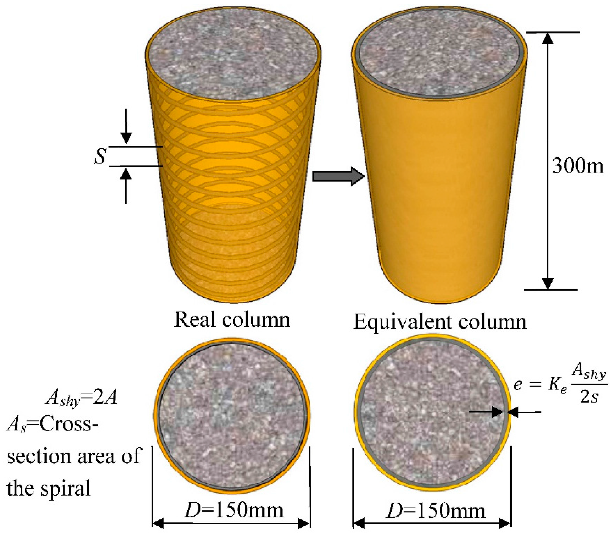
2.2. Fabrication of Specimens

Unidirectional glass fiber sheets were firstly cut into appropriate lengths for each layer category of GFRP tubes. The GFRP sheets were saturated with epoxy on the surfaces using paintbrushes or rollers and then wrapped around the PVC tubes. The installed tubes had a fiber orientation in the circumferential direction of the cylinders. Two narrow glass fiber sheets were wrapped around both ends of the tubes to avoid premature failure of the specimens. The GFRP tubes were formed and pulled out from PVC tubes after three to four hours, and then dried for seven days. The installed SR together with the GFRP tube was termed as a GFRP–SR tube. Concrete was cast and poured into the GFRP–SR tube.

2.3. Material Properties

2.3.1. Concrete

The concrete was designed with a 28 day compressive strength of 30 MPa. The concrete mix design is shown in Table 2. The tested average compressive strength and corresponding strain of the concrete were 30.04 MPa and 0.002, respectively.
Table 2. Concrete mixture proportions.
fc' (MPa)W/CWater (kg/m3)Cement (kg/m3)Fine Aggregates (kg/m3)Coarse Aggregates (kg/m3)
300.51195.0382.3583.31239.4

2.3.2. Steel Reinforcement

The mechanical properties of the steel bars were determined using five specimens of the steel bars through the standard tests. The yield strength of the bar was 356 MPa.

2.3.3. FRP Composites

Unidirectional glass FRP sheets with ply thickness of 0.436 mm were used to fabricate the tubes. The mechanical properties of GFRP, including the modulus, tensile strength, and tensile strain, were determined through flat coupon tensile test, in accordance with ASTM D3039-M08 [60], as displayed in Figure 3. Prior to testing, aluminum flat bars were glued to the ends of the coupons to avoid premature failure of the coupon ends. The fiber volume fraction (ρf) of the FRP coupons was 25.23% and ρf of FRP tubes are provided in Table 1. The measured average tensile modulus, ultimate tensile strength, and tensile strain were 60.8 GPa, 967 MPa, and 0.016, respectively and these properties provided by the manufacturers were 63.0 GPa, 1189 MPa, and 0.019, respectively.
Figure 3. GFRP tension coupon details (unit: mm).
Polymers 07 00851 g003

2.4. Ductility Index and Energy Consideration for Ductility Index at Failure

A ductility index, μ (Jo et al. [61]), to describe ductility is given by:
μ = 1 2 ( E t o t E e l + 1 )
and
E t o t = E i e l + E e l
where Etot is the total energy absorbed during deformation; Eiel is the inelastic energy absorbed during deformation; and Eel is the elastic energy absorbed during deformation (see Figure 4).
Figure 4. Evaluation method of elasticity energy.
Polymers 07 00851 g004
In general, µ given as the ultimate strain divided by yielding strain has been normally used to evaluate the ductility of confined concrete. However, the yield point was difficult to define in this paper because of the slight difference observed in the stress–strain behavior of the steel and FRP composites, such that the conventional definition of the ductility index could not be used.
The Eel can be estimated from unloading tests. Eel can be computed as the area of the triangle formed at the failure load by the line having the weighted average slope of the two initial straight lines of the load–deflection curve, as illustrated in Figure 4. The slope is given by:
S = P 1 S 1 + ( P 2 P 1 ) S 2 P 2
where S1 and S2 are the slopes of the two initial straight lines of the load–deflection curve.
In this research, the ductility index was calculated by obtaining an average slope with the same method through curve fitting, as shown in Figure 4.

2.5. Test Instrumentation

All of the specimens were tested at the Structural Laboratory of Hunan University using a compression machine (WeiKE Machine, hydraulic, Zaozhuang, China) under stress control mode with a constant rate of 0.20 MPa/s based on ASTM C39 [62]. The acquired data included the applied axial load (P), axial deformation of concrete, transverse and axial strains of the GFRP tube, and the tensile strain of SR. As shown in Figure 5, the axial displacement was measured using four linear variable displacement transducers placed at the middle portion of the cylinders. For each GFRP–SR confined concrete specimen, four hoop strain gauges with a gauge length of 10 mm and four axial strain gauges with a gauge length of 20 mm were installed at the middle portion of the specimen. Two gauges with a gauge length of 5 mm were mounted at the middle portion of SR to measure the tensile strain. Although the GFRP tube was not directly bearing on the loading plates at the ends, some axial stress existed in the GFRP tube because of the bond transfer between tube and concrete.
Figure 5. Test set-up and instrumentation configurations.
Polymers 07 00851 g005

3. Results and Discussion

3.1. Failure Modes

The failure modes of GFRP–SR confined concrete cylinder specimens are shown in Figure 6. All of the confined concrete specimens failed by tensile rupture of the GFRP tube in the hoop direction. The failure process was also quiet because of a relatively gradual rupture of the GFRP tube, unlike the explosive process observed in CFRP confined concrete cylinders. The failure situations of all specimens were quite similar. However, for specimens with lower SR volumetric ratio, more core concrete crushed and squeezed out after the rupture of GFRP compared with the higher ones. Moreover, the axial compressive strength and strain of specimens with higher SR volumetric ratio and more layers of GFRP tube were larger, resulting in a higher degree of fragmentation of the concrete core. In general, the GFRP tube and SR showed synchronized transverse deformation at the initial stage of loading and the concrete core was well-preserved when the GFRP tube ruptured because of the confinement of SR. However, the residual compressive behaviors of concrete core confined by SR with different SR volumetric ratios were quite different, i.e., with the increase of compressive load, relatively more core concrete between the larger pitch of SR began to drop out and more apparent axial deformation occurred for core concrete confined with a lower volumetric ratio of SR. Finally, the SR failed with a noise by tearing apart at random points for the core concrete confined with high SR volumetric ratio, but which did not occur to the specimens with relatively low SR volumetric ratio.
Figure 6. Typical failure of specimens.
Polymers 07 00851 g006

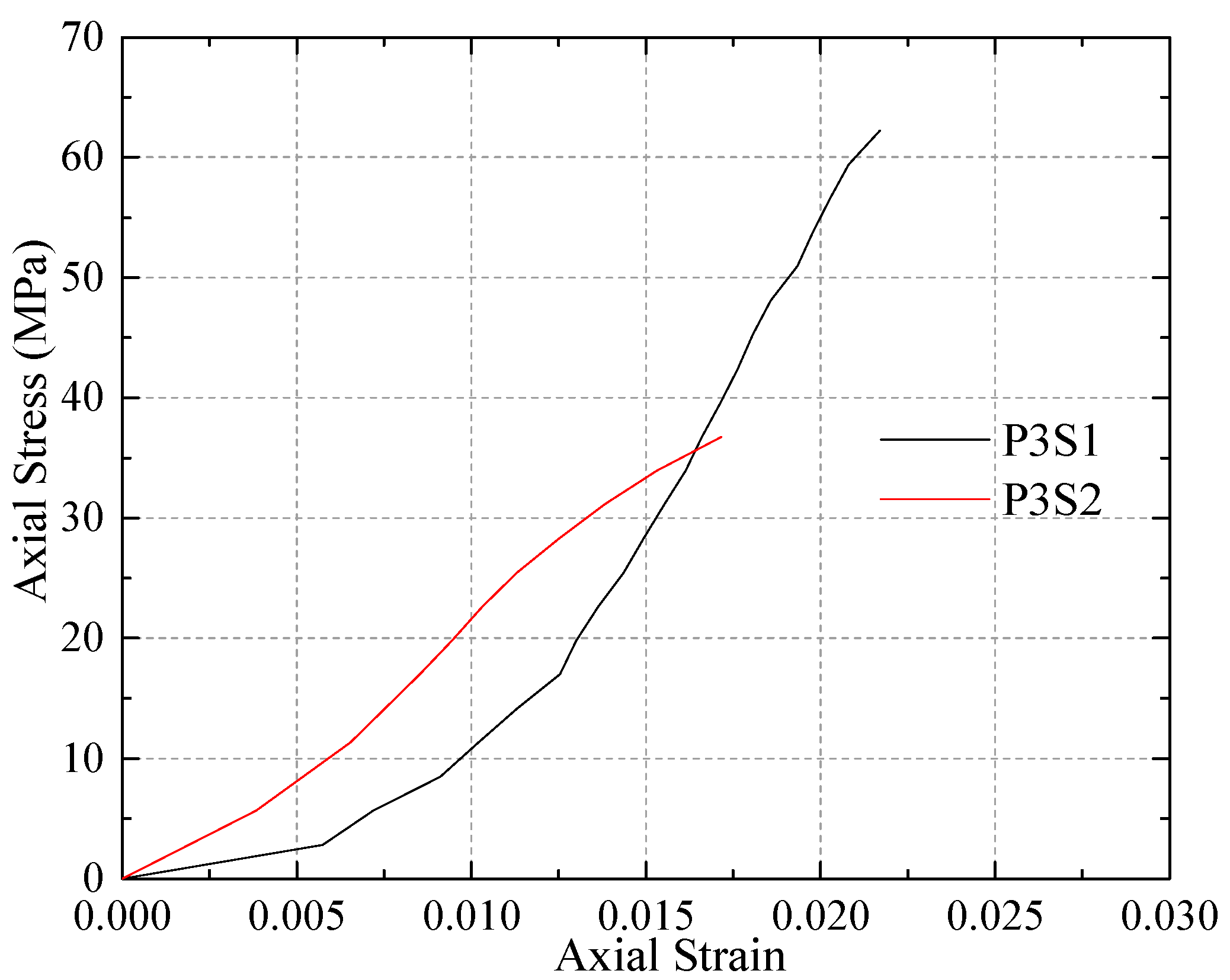
3.2. Axial Stress–Strain Relationships

Axial stress versus axial and transverse strain curves of unconfined and confined concrete are shown in Figure 7. In general, the curves can be divided into three stages: the first linear stage, transition zone, and the second linear stage. At the initial stage, the stress–strain responses of all the confined concrete were similar to that of the unconfined concrete, indicating that the confinement of the GFRP–SR tube was not activated. When the axial stress became higher than the unconfined concrete strength, fc', the concrete lateral strain increased obviously, resulting in the increase of the confinement lateral pressure. Once the GFRP–SR tube was activated to confine the concrete, the curve entered the nonlinear transition region, where considerable micro-cracks appeared in the concrete and led to the lateral expansion of the concrete core. Similar to the conventional FRP-confined concrete with a sufficient level of FRP confinement [18], the stress–strain curves of GFRP–SR confined concrete also exhibited an ascending second linear branch. However, a distinct difference was found between the stress–strain curves of conventional FRP-confined concrete and GFRP–SR confined concrete, i.e., the transition zone of the stress–strain curve of GFRP–SR confined concrete was much longer than that of conventional FRP-confined concrete after reaching the ultimate compressive strength of the unconfined concrete. It is believed this difference is attributed to the stronger confinement provided by the GFRP–SR tube. Unlike conventional FRP-confined concrete, less and slower cracks appeared in the core of GFRP–SR confined concrete after reaching the ultimate compressive strength of the unconfined concrete, which resulted in a less and relatively slow decrease of stiffness.
Figure 7. Axial stress versus axial and lateral strain curves for GFRP–SR confined cylinder specimens with SR volumetric ratio of (a) 3% and (b) 1.5%.
Polymers 07 00851 g007

3.3. Residual Compressive Behavior of Confined Concrete after Rupture of the GFRP Tube

Upon rupture of the GFRP tube, a compressive test was further performed to evaluate the residual compressive behavior of the SR-confined concrete core. The axial compressive stress versus the axial strain curves of SR-confined concrete upon rupture of GFRP are shown in Figure 8. The residual compressive strength of the concrete core with SR confinement was still larger than the ultimate compressive strength of the unconfined concrete. The concrete core with higher SR volumetric ratio showed a larger residual compressive strength; the compressive strengths of specimens P3S2 and P3S1 were 36.8 MPa and 62.2 MPa, respectively. Therefore, the volumetric ratio of SR had a significant influence on the compressive strength of GFRP–SR confined concrete cylinders upon rupture of the GFRP tube. The high residual compressive strength is highly significant in the context of sustaining the residual structure in strong earthquakes. The recent studies by [63,64,65] have focused on the use of polypropylene fiber ropes (PPFRs) as external reinforcement to confine concrete cylinders. Similar to GFRP–SR confined concrete, when used in hybrid confining schemes [64] with GFRP jackets, external PPFRs presented no fracture even after the fracture of the GFRP and furthermore they could be reused. Adequate PPFR confinement could resist the fracture of the FRP jacket and presented an acceptable temporary load drop. Then, further upgrade of the bearing load capacity of the columns followed. Moreover, extremely high ultimate strain can also be achieved for concrete confined by FRP jackets with a large rupture strain, which leads to more ductile behavior and greater energy absorption [6].
Figure 8. Axial stress versus axial strain curves of the reloaded confined concrete.
Polymers 07 00851 g008

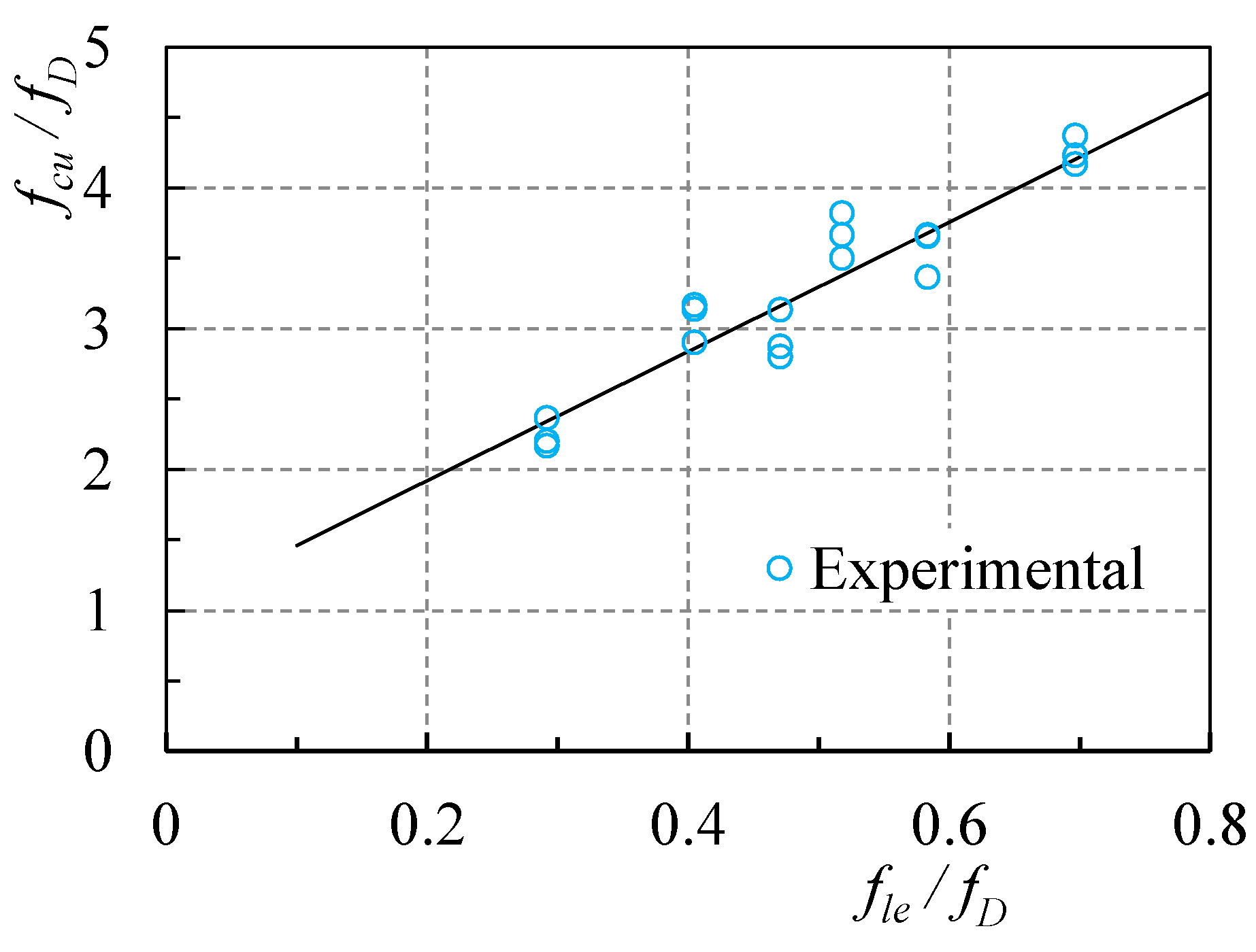
3.4. Ultimate Condition

Table 3 presents a summary of the experimental test results. A significant enhancement of the strength, as well as the ductility for the GFRP–SR confined cylinders, was achieved by increasing the thickness of GFRP tubes and the volumetric ratio of SR. For example, the average compressive strength obtained for specimens P1S2 and P2S1 were 70.95 MPa and 109.71 MPa, respectively, whereas the average ultimate compressive strain determined for specimens P1S2 and P2S1 were 0.0222 and 0.0244, respectively. The ultimate condition shown in Table 3 was dominated by the rupture of the GFRP tube and the rupture of GFRP in specimens with higher volumetric SR ratio, which corresponded to larger axial compressive strength and strain, as reported also by Lee et al. [34]. The concrete ultimate axial strains (εcu) corresponding to failure varied widely from 0.0222 to 0.03, with a tendency to increase for specimens with more GFRP layers and higher SR volumetric ratio. Moreover, the maximum actual lateral confining pressures of SR and GFRP tubes (denoted by fls,a and flf,a, respectively) are also provided in Table 3. Increasing the volumetric SR ratio for a cylinder specimen with the same FRP confinement results in increased maximum actual lateral confining pressures of GFRP tubes, which was different from the test results of Eid and Paultre (2009) [33] for CFRP-TSR confined concrete. Thus, the presence of SR helped not only in confining the lateral deformation of the core concrete, but also in increasing the confinement action of the GFRP tubes.
The recorded GFRP strains corresponding to failure (εfu,a) ranged from 0.0121 to 0.0154, which were approximately 75.6%–96.2% of the rupture strains obtained for the tensile coupons (εfu).
Based on the test results, the difference between the actual FRP rupture strain in FRP–SR-confined concrete specimens and the FRP ultimate tensile strain obtained from a standard tension coupon test can be attributed to the following: (a) the non-uniform deformation of cracked concrete; and (b) the stress state in the GFRP tube was not a strictly pure tension condition as that for the flat coupon tension tests, explained by Matthys et al., (1999) [4], Xiao et al., (2000) [13], De Lorenzis and Tepfers (2003) [43], and Lim and Ozbakkaloglu (2014) [66]. Moreover, according to test results in Table 3, the inelastic energy absorbed by confined concrete cylinders corresponding to failure was much more than the elastic energy absorbed, and the elastic-to-inelastic energy dissipation ratios were relatively constant.
Table 3. Results of confined concrete cylinder specimens (150 mm × 300 mm).
Specimenfc' (MPa)μEc (kJ)εc'εfuEtot (kJ)εcuεcuc'fcufcu/fc'εfu,aεfu,afuflf,a (MPa) fls,a (MPa)
P1S130.045.770.510.0050.0167.580.02234.4686.242.870.01400.8754.955.16
P2S130.045.810.510.0050.01611.030.02444.88109.713.660.01460.91310.325.16
P3S130.046.060.510.0050.01617.910.03006.00131.174.370.01540.96316.325.16
P1S230.045.710.510.0050.0166.560.02224.4470.952.370.01210.7564.272.31
P2S230.045.760.510.0050.0168.230.02414.8294.243.140.01340.8389.482.31
P3S230.045.950.510.0050.01613.300.02865.72114.673.820.01480.92515.702.31

3.5. Influence of Experiment Variables

3.5.1. SR

Figure 9 shows an indication of the effectiveness of the dual confinement mechanism (SR and GFRP). It shows the relationship and development of the lateral strains in SR and FRP for specimens P1S2 (Figure 9a) and P3S2 (Figure 9b). The initial portions of the curves show that the tensile strain developed in SR, εh, was quite similar to the strain developed in the FRP, εf. However, at the same level of axial strain after the unconfined concrete strain, εc', TSR strain was less affected than FRP strain. Therefore, the inelastic expansion behavior of the concrete had a greater influence on εf than on εh. This result was also reported by Eid and Paultre [33]. The SR reached its yield strength prior to the rupture of FRP, indicating that at the FRP rupture state, the specimens were subjected to the maximum confining pressures imposed by SR and FRP composite, respectively.
Figure 9. Lateral strain developed in the SR and FRP for specimens (a) P1S2 and (b) P3S2.
Polymers 07 00851 g009
A study by Ozbakkaloglu et al. [67] reviewed and assessed 88 existing FRP-confined concrete models for FRP-confined concrete in circular sections. According to the assessment results, the strength model proposed by Teng et al. [47] is the only analysis-oriented one among the several top performing models. Figure 10 shows the comparison between the analytical axial stress–strain curves of GFRP-confined concrete obtained from Teng et al. [47] and the experimental results of GFRP–SR confined concrete in this paper. As shown in Figure 10, the transition zone of GFRP–SR confined concrete was much longer than that of conventional FRP-confined concrete after reaching the ultimate compressive strength of the unconfined concrete. Moreover, a significant enhancement of strength as well as ductility for the GFRP-confined cylinders was achieved by adding SR, e.g., the compressive strength and strain of specimen P1S2 were 70.95 MPa and 0.0222, respectively, whereas for concrete confined by one layer GFRP, the compressive strength and strain were 48.43 MPa and 0.017, respectively.
Figure 10. Comparison between axial stress–strain curves of GFRP-confined concrete or SR-confined concrete and the experimental results of GFRP–SR confined concrete.
Polymers 07 00851 g010
As shown in Table 3, Etot = 8.23 and 11.03 kJ and Etot = 13.30 and 17.91 kJ were obtained for specimens P2S2 and P2S1 and for specimens P3S2 and P3S1, which had an energy gain of 2.80 and 4.61 kJ, respectively. Thus, the volumetric SR ratio had more significant influence on the energy dissipation of confined concrete with more GFRP layers.

3.5.2. Numbers of FRP Layers

Based on the current test results, the average ratio εfu,afu increased for the concrete cylinder specimens with higher volumetric SR ratio and more FRP layers (see Table 3), e.g., the average ratios εfu,afu = 0.875, 0.913, and 0.756 were obtained for specimens P1S1, P2S1 and P1S2, respectively. Moreover, the GFRP layers had a more significant influence on the energy dissipation of confined concrete with higher volumetric SR ratio (e.g., Etot = 11.03 kJ and 17.91 kJ for specimens P2S1 and P3S1 and Etot = 8.23 kJ and 13.30 kJ for specimens P2S2 and P3S2, which were equivalent to energy gain of 6.88 kJ and 5.07 kJ, respectively; Table 3).
The Légeron and Paultre (2003) [48] model, is suitable to represent the axial behavior of circular concrete columns of normal- and high-strength concrete (20–140 MPa) confined by normal- or high-strength (300–1400 MPa) confinement steel. This model, which predicts experimental results with good accuracy [59], is defined by ascending and descending branches, which is the typical behavior of TSR-confined concrete. The comparison between the analytical axial stress–strain curves of SR-confined concrete obtained from Légeron and Paultre (2003) [48] and the experimental results of GFRP–SR confined concrete is showed in Figure 10. As shown in Figure 10, different from SR-confined concrete, the axial stress–strain curve of GFRP–SR confined concrete showed a much longer nonlinear transition zone and an ascending second linear branch, which result in much higher axial ultimate stress.

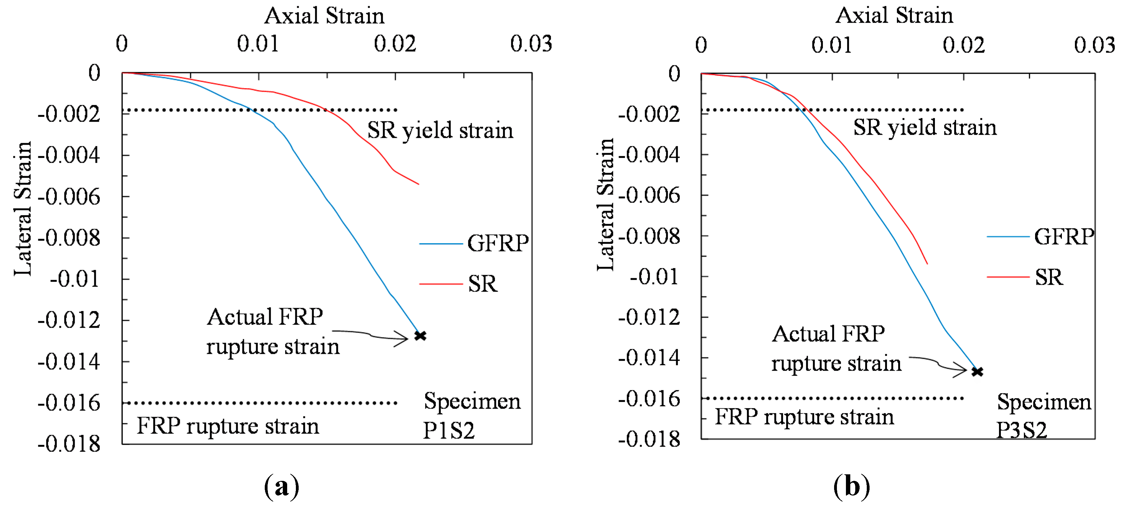
3.6. Axial-Transverse Strain Responses

Recent studies by Lim and Ozbakkaloglu (2015) [68] and Ozbakkaloglu et al. (2013) [67] reviewed and assessed a number of existing models on lateral strain-to-axial strain relationship of confined concrete. According to the assessment results, the model proposed by Teng et al. (2007) [47] showed a better model performance compared with its counterparts, by adding the influence of TSR, this model was further revised and proposed by Teng et al. (2014) [57] for FRP–TSR confined concrete. Moreover, based on a large number of experimental test results of both FRP-confined and actively confined concretes, a generic model was proposed by Lim and Ozbakkaloglu (2015) [68] to describe the lateral strain-to-axial strain relationship of confined concrete, which can predict the trend and critical coordinates of the lateral strain-to-axial strain curves of both FRP-confined and actively confined concretes accurately [68]. The predictions based on models proposed by Lim and Ozbakkaloglu (2015) [68] and Teng et al. (2014) [57] are compared with experimental results for the lateral strain-to-axial strain curves of GFRP-SR confined concrete specimens, as illustrated in Figure 11. It is evident from Figure 11 that the direct use of the Lim and Ozbakkaloglu [68] model results in a higher value of slope, vc', but provides more accurate predictions for initial and transition parts of the curves than Teng’s model [57].
Figure 11. Comparison of model predictions with experimental lateral strain-to-axial strain curves.
Polymers 07 00851 g011
The following equations were adopted by Lim and Ozbakkaloglu (2015) [68] for the axial strain–hoop strain relationship:
ε c = ε h ν 0 [ 1 + ( ε h ν 0 ε c ' ) n ] 1 / n + 0.04 ε h 0.7 [ 1 + 21 ( f l e f c ' ) 0.8 ]
ν 0 = 8 × 10 6 f c ' 2 + 0.0002 f c ' + 0.138
ε c ' = ( 0.067 f c ' 2 + 29.9 f c ' + 1053 ) × 10 6
n = 1 + 0.03 f c '
where εc is the axial strain, εh is the lateral strain, fle is the corresponding confinement pressure for a given lateral strain, v0 is the initial Poisson’s ratio of concrete, fc' is the peak unconfined concrete strength in MPa, εc' is the peak unconfined concrete strain, n is the curve-shape parameter to adjust the initial transition radius of the predicted lateral strain-to-axial strain relationship curve.
In this study, by adding the influence of SR, a revised model based on the expressions proposed by Lim and Ozbakkaloglu (2015) [68] was suggested to describe the lateral strain-to-axial strain relationship curve of GFRP–SR confined concrete, which is given by the following equation:
ε c = ε h ν 0 [ 1 + ( ε h ν 0 ε c ' ) n ] 1 / n + 0.04 ε h 0.7 [ 1 + 21 ( f l f f c ' ) 0.8 + 2.6 ( α f l s f c ' ) 0.8 ]
where α = 1.59 + 15.1ρls [57], ρls is the ratio between the confining stiffness of the FRP jacket and the effective confining stiffness of SR, which is proposed by Teng et al. (2014) [57] to be the parameter to account for the interaction between FRP and SR:
ρ l s = E f t s d s K e E s A s D
where Es, As, ds = elastic modulus, cross-sectional area and diameter of center line of SR.
Figure 11 shows good agreement between the analytical curves obtained from the proposed model and experimental results for three specimens P2S1.
Note that the value of vc' decreases either with an increase in the yield strength of the steel or with an increase in the elastic modulus of the fiber material. This is consistent with the experimental observations [13,33,66,69] or the analytical researches [13,59,69,70] for concrete with single or combined confinement.

4. Analytical Modeling for Concrete Confined with Both GFRP Tubes and SR under Monotonic Compression

The test results indicated that concrete cylinders showed higher strength and ductility when confined with both SR and GFRP composites. Most of the models for confined concrete were based on several researches on concrete confined with one material, and therefore cannot represent the behavior of concrete confined with both SR and FRP. The predictions of the models proposed by Lee et al., (2010) [35], Teng et al., (2014) [57], Chastre and Silva (2010) [58] and Eid and Paultre (2008) [59] are compared with experimental results in Figure 12 for the stress–strain curves of GFRP–SR confined concrete specimens with a low (Specimen P3S2) or medium (Specimen P3S1) confining pressure from SR. The predicted curves all terminate at a point where the experimental FRP rupture strain (εfu,a) is reached. It is evident from Figure 12 that models proposed by Teng et al., (2014) [57] and Chastre and Silva (2010) [58] are superior to the two other existing models (Lee et al., (2010) [35]; Eid and Paultre (2008) [59]). However, the prediction of the model proposed by Teng et al., (2014) [57] significantly underestimates the responses of GFRP–SR confined concrete specimens at the second linear branches of the stress–strain curves. Moreover, the direct use of the Chastre and Silva (2010) [58] model result in higher ultimate axial stresses for the GFRP–SR confined concrete specimens, but provides reasonable predictions for the types of stress-strain curves. Since the model described in Chastre and Silva (2010) [58] was developed based on several researches on CFRP retrofitted circular columns with 150–400 mm diameter and H/D between 3 and 5, it can be further modified to predict the stress-strain curve of GFRP–SR confined concrete based on tests results.
Figure 12. Performance of models for GFRP–SR confined concrete with a (a) low (b) medium level of steel confinement.
Polymers 07 00851 g012

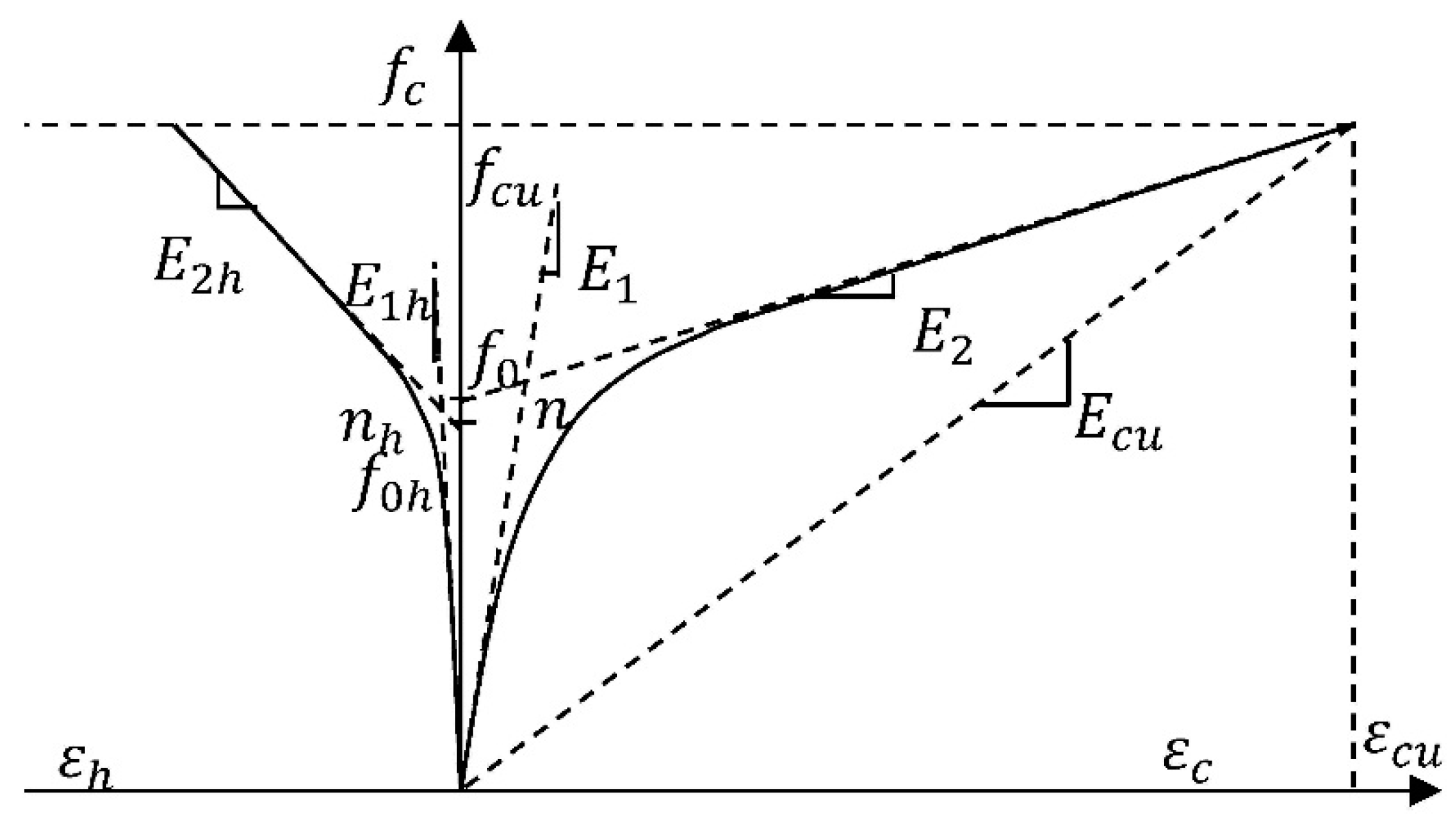
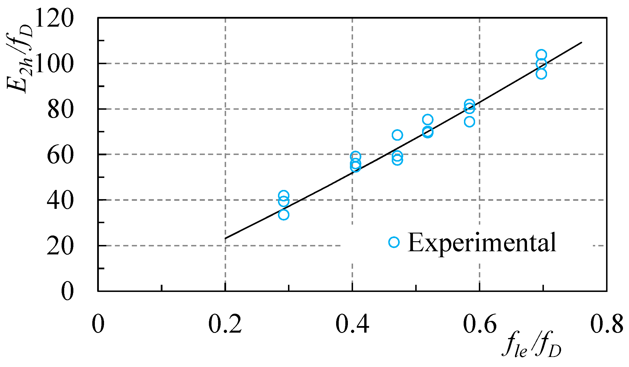
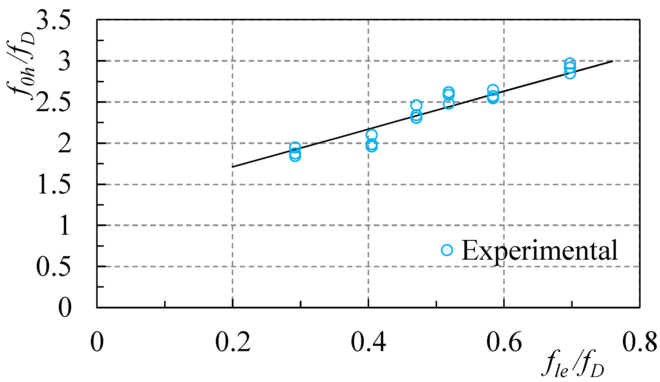
4.1. Proposed Stress Equations

For the monotonic actions, The compressive strength of confined concrete can be expressed in the following common form [51,52,67,71]:
f c u = f D + k 1 f l e
Equation (15) includes the contribution of the confinement given by the lateral steel reinforcement and by the FRP tube, and this equation considers superposed effects at rupture. Moreover, Equation (15) was calibrated for GFRP and SR (k1 = 4.6) through experimental tests (Figure 13).
The compressive strength of the concrete cylinder, fD [72], can be given by [48,67,70]:
f D = α f c '
where α is the scale effects coefficient ((1.5 + D/H)/2 = 1 in this paper), and D and H are the diameter and the height of the cylinder, respectively.
Assuming the aforementioned superposed effects at rupture of the FRP tube (flf) and the steel spirals (fls) confinement, the lateral confining pressure (fle) is defined by:
f l e = f l f + f l s
where fls and flf are given by Equations (3) and (4), respectively, and fh = fhy [48].
Figure 13. Relationship between fcu, fD and fle of concrete cylinders confined with GFRP and SR.
Polymers 07 00851 g013
The axial strain in rupture (εcu) can be expressed in the following form [54]:
ε c u = k 2 ε c 0 ( f l e f D ) 0.7
where εc0 is adapted from Eurocode 2 (2004) [73]:
ε c 0 = 0.7 1000 ( f c ' ) 0.31
Equation (18) was obtained for GFRP and SR (k2 = 20) by regression of experimental data (Figure 14) of concrete cylinders confined with GFRP tubes and SR.
Figure 14. Relationship between εcu/εc0 and fle/fD of concrete cylinders confined with GFRP and SR.
Polymers 07 00851 g014

4.2. Proposed Stress–Strain Model for FRP–SR Confined Concrete in Compression

Note that the model proposed for the GFRP–SR confined concrete stress–strain curve of cylinders subjected to monotonic axial compression was based on the stress–strain law depicted in Figure 15.
Figure 15. Proposed stress–strain model for GFRP–SR confined concrete in compression.
Polymers 07 00851 g015
For the monotonic actions, the stress–axial strain relationship was bi-linear for the concrete confined with GFRP and SR (Figure 15) and was based on a versatile expression of four parameters (E1, E2, f0, n), as initially proposed by Richard and Abbott [74]:
f c = ( E 1 E 2 ) ε c [ 1 + ( ( E 1 E 2 ) ε c f 0 ) n ] 1 n + E 2 ε c f c u
With the parameters calibrated according to available experimental results:
{ E 1 = 3950 f D ( a ) E 2 = 0.73 E c u f l e f D ( b ) f 0 = f D + 1.75 f l e ( c )
Ecu can be estimated applying Equations (15) and (18) to the following expression:
E c u = f c u ε c u
The axial stress–lateral strain curve was also bi-linear:
f c = ( E 1 h E 2 h ) ε h [ 1 + ( ( E 1 h E 2 h ) ε h f 0 h ) n h ] 1 n h + E 2 h ε h f c u
with
{ E 1 h = E 1 ν ( a ) E 2 h = 150 ( f l e ) 1.16 ( f D ) 0.16   ( b ) f 0 h = 1.25 f D + 2.3 f l e ( c )
For the axial stress–axial strain curve, the slope of the first branch was considered essentially, followed by the curves of the unconfined concrete, given that the GFRP–SR tube had a passive behavior and was only activated for a stress level similar to the maximum stress of the unconfined concrete, which was defined by Equation (21a) [1,54,58].
The slope of the second branch, E2 (Equation (21b)), was experimentally calibrated (Figure 16) with the function of the slope of confinement of several concrete cylinders confined with GFRP tubes and SR. The stress value f0 (Equation (21c)) and the parameter n = 2 can be estimated based on the calibration of curves through the experimental tests (Figure 17).
Figure 16. Parameter E2-experimental calibration with concrete cylinders confined with GFRP tubes and SR.
Polymers 07 00851 g016
Figure 17. Parameter f0-experimental calibration with concrete cylinders confined with GFRP tubes and SR.
Polymers 07 00851 g017
For the axial stress–lateral strain curve, the slope of the first branch was dependent on the concrete Poisson’s ratio (v = 0.16), which is given by Equation (24a). The parameter nh was assumed to be 2. The slope of second branch (Equation (24b)) and the parameter f0h (Equation (24c)) were determined after experimental calibration, as shown in Figure 18 and Figure 19.
Figure 18. Parameter E2h-experimental calibration with concrete cylinders confined with GFRP tubes and SR.
Polymers 07 00851 g018
Figure 19. Parameter f0h-experimental calibration with concrete cylinders confined with GFRP tubes and SR.
Polymers 07 00851 g019

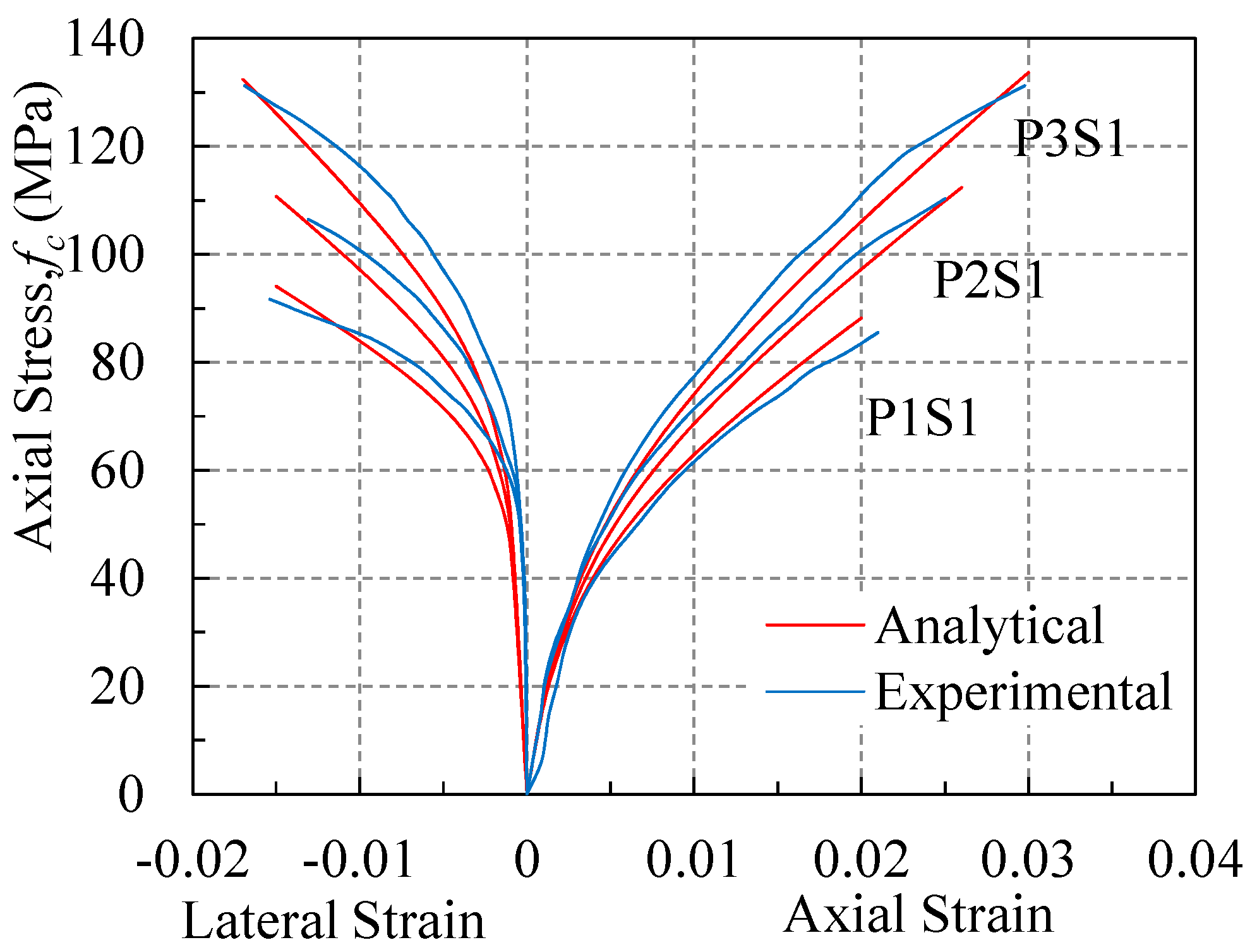
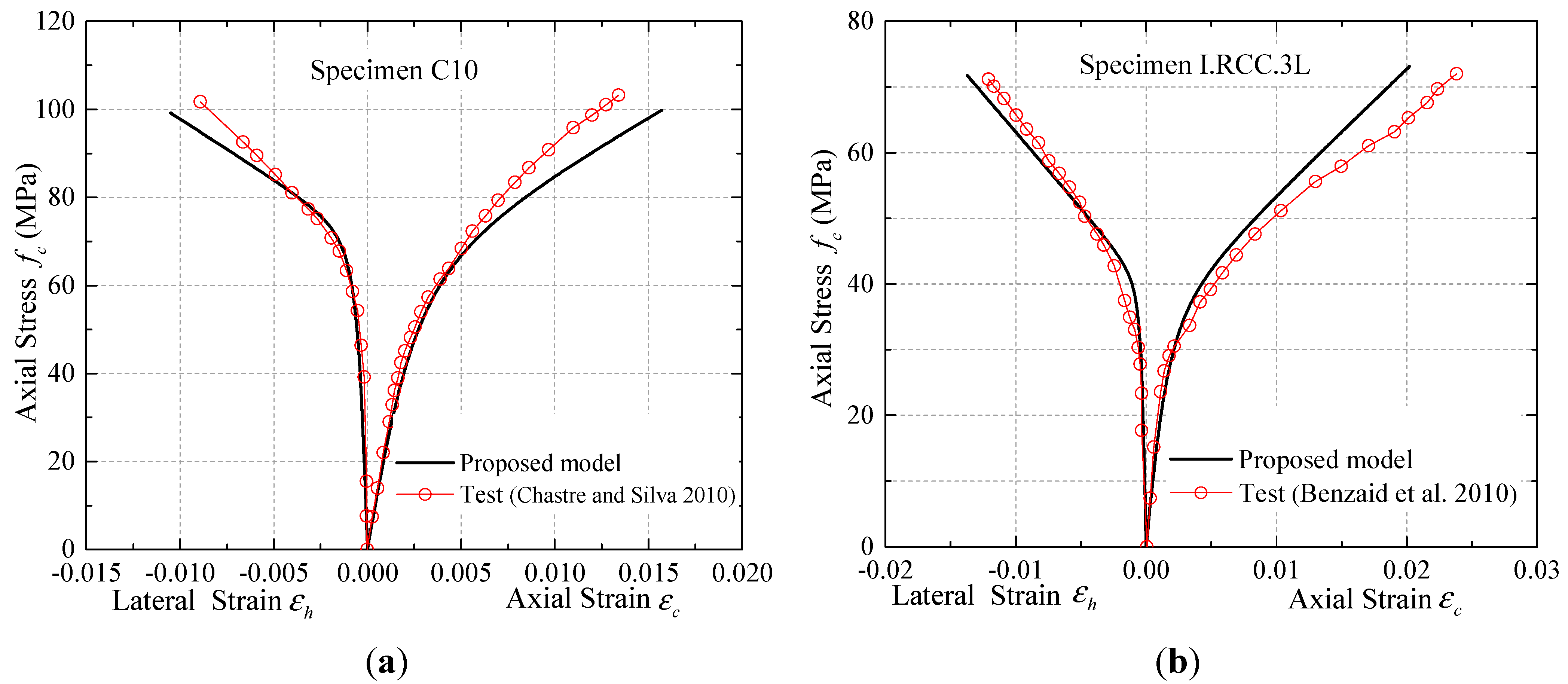
4.3. Comparison of the Model Proposed with the Experimental Results

Figure 20 shows good agreement between the analytical curves obtained from the proposed stress–strain model and experimental results for three specimens P1S1, P2S1, and P3S1. Moreover, the predictions of the proposed model are compared in Figure 21 for the stress–strain curves of FRP–TSR confined concrete with experimental results from Chastre and Silva (2010) [58] and Benzaid et al., (2010) [18], which were not used in the development of the proposed model. Only typical comparisons are shown in Figure 21, but those for other specimens are similar. Figure 21 shows that the proposed model is capable of providing accurate predictions for the stress–strain curves.
Figure 20. Comparison of compressive stress–strain curves between the predictions and test results for Specimens P1S1, P2S1, and P3S1.
Polymers 07 00851 g020
Figure 21. Performance of proposed model for FRP–TSR confined concrete: (a) Specimen C10 from Chastre and Silva (2010) [58]; (b) Specimen I.RCC.3L from Benzaid et al., (2010) [18].
Polymers 07 00851 g021

5. Conclusions

  • Significant increase in strength and ductility of concrete can be achieved by using GFRP tubes and SR. Unlike the explosive process observed in CFRP confined concrete cylinders, the failure process of GFRP–SR confined concrete was quiet and the GFRP–SR confined concrete had a good residual compressive strength after the rupture of GFRP.
  • Increasing the volumetric SR ratio for a cylinder specimen with the same FRP confinement results in increased maximum actual lateral confining pressures of GFRP tubes, which is different from the test results of Eid and Paultre (2009) [33] for CFRP–TSR confined concrete.
  • The stress–strain performances of concrete confined with GFRP tube and SR exhibited an ascending bilinear shape with a long transition zone around the stress level of unconfined concrete strength. A model was proposed to describe the relationships between the axial stress–axial strain and axial stress–lateral strain; this model showed good agreement with the experimental results.
  • The test results were compared with predictions of some existing models. For GFRP–SR confined concrete, models proposed by Teng et al., (2014) [57] and Chastre and Silva (2010) [58] are superior to the two other existing models (Lee et al., 2010 [35]; Eid and Paultre 2008 [59]). The direct use of the Chastre and Silva (2010) [58] model significantly overestimates the ultimate axial stresses of the GFRP–SR confined concrete specimens, but provides reasonable predictions for the types of stress–strain curves.
  • The inelastic energy absorbed by confined concrete cylinders corresponding to failure was much more than the elastic energy absorbed, and the elastic-to-inelastic energy dissipation ratios were relatively constant.

Acknowledgments

The tests on concrete cylinders confined by GFRP–SR tubes were funded by Hunan Provincial Natural Science Foundation of China (No. 2015JJ1004), National Basic Research Program of China (973 program, Project No. 2012CB026200), and the Sci-Tech Support Plan of Hunan Province (Project No. 2014WK2026). The authors would like to thank Yan Xiao and Giorgio Monti for their valuable input. Special thanks to graduate students Peng Yin and Kai Huang for their help in preparing the specimens and conducting the tests.

Author Contributions

Liang Huang and Xiaoxun Sun conceived and designed the experiments; Liang Huang and Xiaoxun Sun performed the experiments; Liang Huang, Xiaoxun Sun and Libo Yan analyzed the data; Liang Huang and Deju Zhu contributed reagents/materials/analysis tools; Liang Huang, Xiaoxun Sun and Libo Yan wrote the paper.

Conflicts of Interest

The authors declare no conflict of interest.

References

  1. Ahmad, S.M.; Shah, S.P. Stress–strain curves of concrete confined by spiral reinforcement. ACI Struct. J. 1982, 79, 484–490. [Google Scholar]
  2. Mander, J.B.; Priestley, M.J.N.; Park, R. Observed stress strain behavior of confined concrete. ASCE J. Struct. Eng. 1988, 114, 1827–1849. [Google Scholar] [CrossRef]
  3. Parvin, A.; Brighton, D. FRP composites strengthening of concrete columns under various loading conditions. Polymers 2014, 6, 1040–1056. [Google Scholar] [CrossRef]
  4. Matthys, S.; Taerwe, L.; Audenaert, K. Tests on axially loaded concrete columns confined by fiber reinforced polymer sheet wrapping. ACI Spec. Publ. 1999, 188, 217–228. [Google Scholar]
  5. Lam, L.; Teng, J.G. Ultimate condition of fiber reinforced polymer-confined concrete. J. Compos. Constr. 2004, 8, 539–548. [Google Scholar] [CrossRef]
  6. Dai, J.G.; Bai, Y.L.; Teng, J.G. Behavior and modeling of concrete confined with FRP composites of large deformability. J. Compos. Constr. 2011, 15, 963–973. [Google Scholar] [CrossRef]
  7. Ilki, A.; Peker, O.; Karamuk, E.; Demir, C.; Kumbasar, N. FRP retrofit of low and medium strength circular and rectangular reinforced concrete columns. J. Mater. Civil Eng. 2008, 20, 169–188. [Google Scholar] [CrossRef]
  8. Ozcan, O.; Binici, B.; Ozcebe, G. Seismic strengthening of rectangular reinforced concrete columns using fiber reinforced polymers. Eng. Struct. 2010, 32, 964–973. [Google Scholar] [CrossRef]
  9. Wu, Y.F.; Wei, Y.Y. Effect of cross-sectional aspect ratio on the strength of CFRP-confined rectangular concrete columns. Eng. Struct. 2010, 32, 32–45. [Google Scholar] [CrossRef]
  10. Ozbakkaloglu, T.; Akin, E. Behavior of FRP-confined normaland high-strength concrete under cyclic axial compression. J. Compos. Constr. 2012, 16, 451–463. [Google Scholar] [CrossRef]
  11. Wang, Z.Y.; Wang, D.Y.; Smith, S.T.; Lu, D.G. CFRPconfined square RC columns. I: Experimental investigation. J. Compos. Constr. 2012, 16, 150–160. [Google Scholar] [CrossRef]
  12. Xiao, Y.; Wu, H. Compressive behavior of concrete confined by various types of FRP composite jackets. J. Reinf. Plast. Compos. 2003, 22, 1187–1201. [Google Scholar] [CrossRef]
  13. Xiao, Y.; Wu, H. Compressive behavior of concrete confined by carbon fiber composite jackets. J. Mater. Civil Eng. 2000, 12, 139–146. [Google Scholar] [CrossRef]
  14. Priestley, M.J.N.; Seible, F. Seismic Assessment and Retrofit of Bridges; Structural Systems Researck Project; Report No. SSRP 91103; University of California: San Diego, CA, USA, July 1991; p. 418. [Google Scholar]
  15. Seible, F.; Hegemier, G.A.; lnnamorato, D. Developments in bridge column jacketing using advance composites. In Proceedings of the National Seismic Conference on Bridges and Highways, Federal Highway Administration and California Department of Transportation, San Diego, CA, USA, 10–13 December 1995.
  16. Ma, R.; Xiao, Y.; Li, K.N. Full-scale testing of a parking structure column retrofitted with carbon fiber reinforced composites. J. Constr. Build. Mater. 2000, 14, 63–71. [Google Scholar] [CrossRef]
  17. Teng, J.G.; Chen, J.F.; Smith, S.T.; Lam, L. RC Structures Strengthened with FRP Composites; Research Centre for Advanced Technology in Structural Engineering, Department of Civil and Structural Engineering; The Hong Kong Polytechnic University: Hong Kong, China, December 2000; p. 134. [Google Scholar]
  18. Benzaid, R.; Mesbah, H.; Chikh, N.E. FRP-confined concrete cylinders: Axial compression experiments and strength model. J. Reinf. Plast. Compos. 2010, 29, 2469–2488. [Google Scholar] [CrossRef]
  19. Xie, T.; Ozbakkaloglu, T. Behavior of steel fiber-reinforced high-strength concrete-filled FRP tube columns under axial compression. Eng. Struct. 2015, 90, 158–171. [Google Scholar] [CrossRef]
  20. Vincent, T.; Ozbakkaloglu, T. Influence of fiber orientation and specimen end condition on axial compressive behavior of FRP-confined concrete. Constr. Build. Mater. 2013, 47, 814–826. [Google Scholar] [CrossRef]
  21. Vincent, T.; Ozbakkaloglu, T. Influence of shrinkage on compressive behavior of concrete-filled FRP tubes: An experimental study on interface gap effect. Constr. Build. Mater. 2015, 75, 144–156. [Google Scholar] [CrossRef]
  22. Vincent, T.; Ozbakkaloglu, T. Compressive behavior of prestressed high-strength concrete-filled aramid FRP tube columns: Experimental observations. J. Compos. Constr. 2015, 2015. [Google Scholar] [CrossRef]
  23. Vincent, T.; Ozbakkaloglu, T. Influence of slenderness on stress–strain behavior of concrete-filled FRP tubes: Experimental study. J. Compos. Constr. 2014, 19, 04014029. [Google Scholar] [CrossRef]
  24. Ozbakkaloglu, T.; Vincent, T. Axial compressive behavior of circular high-strength concrete-filled FRP tubes. J. Compos. Constr. 2014, 18, 04013037. [Google Scholar] [CrossRef]
  25. Yan, L.; Chouw, N. Dynamic and static properties of flax fibre reinforced polymer tube confined coir fibre reinforced concrete. J. Compos. Mater. 2014, 48, 1595–1610. [Google Scholar] [CrossRef]
  26. Ozbakkaloglu, T. Behavior of square and rectangular ultra high-strength concrete-filled FRP tubes under axial compression. Compos. B Eng. 2013, 54, 97–111. [Google Scholar] [CrossRef]
  27. Yan, L.; Chouw, N.; Jayaraman, K. Effect of column parameters on flax FRP confined coir fibre reinforced concrete. Constr. Build. Mater. 2014, 55, 299–312. [Google Scholar] [CrossRef]
  28. Zhang, B.; Yu, T.; Teng, J. Behavior of concrete-filled FRP tubes under cyclic axial compression. J. Compos. Constr. 2014, 2014. [Google Scholar] [CrossRef]
  29. Zhao, J.L.; Yu, T.; Teng, J.G. Stress–strain behavior of FRP-confined recycled aggregate concrete. J. Compos. Constr. 2014, 2014. [Google Scholar] [CrossRef]
  30. Monti, G. Confining reinforced concrete with FRP: Behavior and modeling. Compos. Constr. 2002, 2002, 213–222. [Google Scholar]
  31. Richart, F.E.; Brandtzæg, A.; Brown, R.L. Failure of Plain and Spirally Reinforced Concrete in Compression; Bulletin No. 190; Engineering Experiment Station, University of Illinois: Urbana, IL, USA, 1929. [Google Scholar]
  32. Kumutha, R.; Palanichamy, M.S. Investigation of reinforced concrete columns confined using glass fiber-reinforced polymers. J. Reinf. Plast. Compos. 2006, 25, 1669–1678. [Google Scholar] [CrossRef]
  33. Eid, R.; Roy, N.; Paultre, P. Normal- and high-strength concrete circular elements wrapped with FRP composites. J. Compos. Constr. 2009, 13, 113–124. [Google Scholar] [CrossRef]
  34. Triantafyllou, G.G.; Rousakis, T.C.; Karabinis, A.I. Axially loaded reinforced concrete columns with a square section partially confined by light GFRP straps. J. Compos. Constr. 2014, 19, 04014035. [Google Scholar] [CrossRef]
  35. Lee, J.Y.; Yi, C.K.; Jeong, H.S.; Kim, S.W.; Kim, J.K. Compressive response of concrete confined with steel spirals and FRP composites. J. Compos. Mater. 2010, 44, 481–504. [Google Scholar] [CrossRef]
  36. Demers, M.; Neale, K. Confinement of reinforced concrete columns with fibre-reinforced composite sheets—An experimental study. Can. J. Civil Eng. 1999, 26, 226–241. [Google Scholar] [CrossRef]
  37. Matthys, S.; Toutanji, H.; Audenaert, K.; Taerwe, L. Axial load behavior of large-scale columns confined with fiber-reinforced polymer composites. ACI Struct. J. 2005, 102, 258–267. [Google Scholar]
  38. Carey, S.A.; Harries, K.A. Axial behavior and modeling of confined small-, medium-, and large-scale circular sections with carbon fiber-reinforced polymer jackets. ACI Struct. J. 2005, 102, 596–604. [Google Scholar]
  39. Rousakis, T.C.; Karabinis, A.I. Adequately FRP confined reinforced concrete columns under axial compressive monotonic or cyclic loading. Mater. Struct. 2012, 45, 957–975. [Google Scholar] [CrossRef]
  40. De Luca, A.; Nardone, F.; Matta, F.; Nanni, A.; Lignola, G.P.; Prota, A. Structural evaluation of full-scale FRP-confined reinforced concrete columns. J. Compos. Constr. 2010, 15, 112–123. [Google Scholar] [CrossRef]
  41. Tamuzs, V.; Valdmanis, V.; Gylltoft, K.; Tepfers, R. Behavior of CFRP-confined concrete cylinders with a compressive steel reinforcement. Mech. Compos. Mater. 2007, 43, 191–202. [Google Scholar] [CrossRef]
  42. Wang, Y.C.; Restrepo, J.I. Investigation of concentrically loaded reinforced concrete columns confined with glass fiber-reinforced polymer jackets. ACI Struct. J. 2001, 98, 377–385. [Google Scholar]
  43. De Lorenzis, L.; Tepfers, R. Comparative study of models on confinement of concrete cylinders with fiber-reinforced polymer composites. J. Compos. Constr. 2003, 7, 219–237. [Google Scholar] [CrossRef]
  44. Teng, J.G.; Lam, L. Behavior and modeling of fiber reinforced polymer-confined concrete. J. Struct. Eng. 2004, 130, 1713–1723. [Google Scholar] [CrossRef]
  45. Samaan, M.; Mirmiran, A.; Shahawy, M. Model of concrete confined by fiber composites. ASCE J. Struct. Eng. 1998, 124, 1025–1031. [Google Scholar] [CrossRef]
  46. Spoelstra, M.R.; Monti, G. FRP-confined concrete model. J. Compos. Constr. 1999, 3, 143–150. [Google Scholar] [CrossRef]
  47. Teng, J.G.; Huang, Y.L.; Lam, L.; Ye, L.P. Theoretical model for fiber-reinforced polymer-confined concrete. J. Compos. Constr. 2007, 11, 201–210. [Google Scholar] [CrossRef]
  48. Légeron, F.; Paultre, P. Uniaxial confinement model for normal- and high-strength concrete columns. J. Struct. Eng. 2003, 129, 241–252. [Google Scholar] [CrossRef]
  49. Lignola, G.P.; Prota, A.; Manfredi, G. Simplified modeling of rectangular concrete cross-sections confined by external FRP wrapping. Polymers. 2014, 6, 1187–1206. [Google Scholar] [CrossRef]
  50. Kawashima, K.; Hosotani, M.; Yoneda, K. Carbon fiber sheet retrofit of reinforced concrete bridge piers. In Proceedings of Workshop on Annual Commemoration of Chi-Chi Earthquake, National Center for Research on Earthquake Engineering, Taipei, Taiwan, 18 September 2000; pp. 124–135.
  51. Matthys, S. Structural Behavior and Design of Concrete Members Strengthened with Externally Bonded FRP. Ph.D. Thesis, Ghent University, Gent, Belgium, 2000; p. 345. [Google Scholar]
  52. Lam, L.; Teng, J.G. Design-oriented stress–strain model for FRP-confined concrete. Constr. Build. Mater. 2003, 17, 471–489. [Google Scholar] [CrossRef]
  53. Matthys, S.; Toutanji, H.; Taerwe, L. Stress–strain behaviour of large-scale circular columns confined with FRP composites. J. Struct. Eng. 2006, 132, 123–133. [Google Scholar] [CrossRef]
  54. Mander, J.B.; Priestley, M.J.N.; Park, R. Theoretical stress–strain model for confined concrete. J. Struct. Eng. 1988, 114, 1804–1826. [Google Scholar] [CrossRef]
  55. Saafi, M.; Toutanji, H.; Li, Z. Behavior of concrete columns confined with fiber reinforced polymer tubes. ACI Mater. J. 1999, 96, 500–509. [Google Scholar]
  56. Toutanji, H. Stress–strain characteristics of concrete columns externally confined with advanced fiber composite sheets. ACI Mater. J. 1999, 96, 397–404. [Google Scholar]
  57. Teng, J.G.; Lin, G.; Yu, T. Analysis-oriented stress–strain model for concrete under combined FRP-steel confinement. J. Compos. Constr. 2014, 2014. [Google Scholar] [CrossRef]
  58. Chastre, C.; Silva, M.A. Monotonic axial behavior and modelling of RC circular columns confined with CFRP. Eng. Struct. 2010, 32, 2268–2277. [Google Scholar] [CrossRef]
  59. Eid, R.; Paultre, P. Analytical model for FRP-confined circular reinforced concrete columns. J. Compos. Constr. 2008, 12, 541–552. [Google Scholar] [CrossRef]
  60. Standard Test Method for Tensile Properties of Polymer Matrix Composite Materials; ASTM D3039/D 3039M; American Society for Testing and Materials (ASTM): West Conshohocken, PA, USA, 2008.
  61. Jo, B.-W.; Tae, G.-H.; Kwon, B.-Y. Ductility evaluation of prestressed concrete beams with CFRP tendons. J. Reinf. Plast. Compos. 2004, 23, 843–859. [Google Scholar] [CrossRef]
  62. Standard Test Methods for Compressive Strength of Cylindrical Concrete Specimens; ASTM C39; American Society for Testing and Materials (ASTM): West Conshohocken, PA, USA, 2010.
  63. Rousakis, T.C. Elastic fiber ropes of ultrahigh-extension capacity in strengthening of concrete through confinement. J. Mater. Civil Eng. 2013, 26, 34–44. [Google Scholar] [CrossRef]
  64. Rousakis, T.C. Hybrid confinement of concrete by fiber-reinforced polymer sheets and fiber ropes under cyclic axial compressive loading. J. Compos. Constr. 2013, 17, 732–743. [Google Scholar] [CrossRef]
  65. Rousakis, T.C.; Tourtouras, I.S. RC columns of square section—Passive and active confinement with composite ropes. Compos. B Eng. 2014, 58, 573–581. [Google Scholar] [CrossRef]
  66. Lim, J.C.; Ozbakkaloglu, T. Hoop strains in FRP-confined concrete columns: Experimental observations. Mater. Struct. 2014, 2014, 1–16. [Google Scholar]
  67. Ozbakkaloglu, T.; Lim, J.C.; Vincent, T. FRP-confined concrete in circular sections: Review and assessment of stress–strain models. Eng. Struct. 2013, 49, 1068–1088. [Google Scholar] [CrossRef]
  68. Lim, J.; Ozbakkaloglu, T. Lateral strain-to-axial strain relationship of confined concrete. J. Struct. Eng. 2015, 141, 04014141. [Google Scholar] [CrossRef]
  69. Lim, J.; Ozbakkaloglu, T. Factors influencing hoop rupture strains of FRP-confined concrete. Appl. Mech. Mater. 2014, 501, 949–953. [Google Scholar] [CrossRef]
  70. Ozbakkaloglu, T.; Lim, J.C. Axial compressive behavior of FRP-confined concrete: Experimental test database and a new design-oriented model. Compos. B Eng. 2013, 55, 607–634. [Google Scholar] [CrossRef] [Green Version]
  71. Lam, L.; Teng, J.G. Strength models for fiber-reinforced plastic-confined concrete. J. Struct. Eng. 2002, 128, 612–623. [Google Scholar] [CrossRef]
  72. Concrete Core Testing for Strength; CS-11; Concrete Society: London, UK, 1976.
  73. Eurocode 2: Design of Concrete Structures: Part 1–1: General Rules and Rules for Buildings; British Standards Institution: Brussels, Belgium, 2004.
  74. Richard, R.M.; Abbott, B.J. Versatile elastic–plastic stress–strain formula. J. Eng. Mech. Division 1975, 101, 511–515. [Google Scholar]

