
Decorating Nanoparticle Surface for Targeted Drug Delivery: Opportunities and Challenges


Abstract
:
1. Introduction
2. Experimental Studies
2.1. Amphiphilic Polymer-Decorated NPs
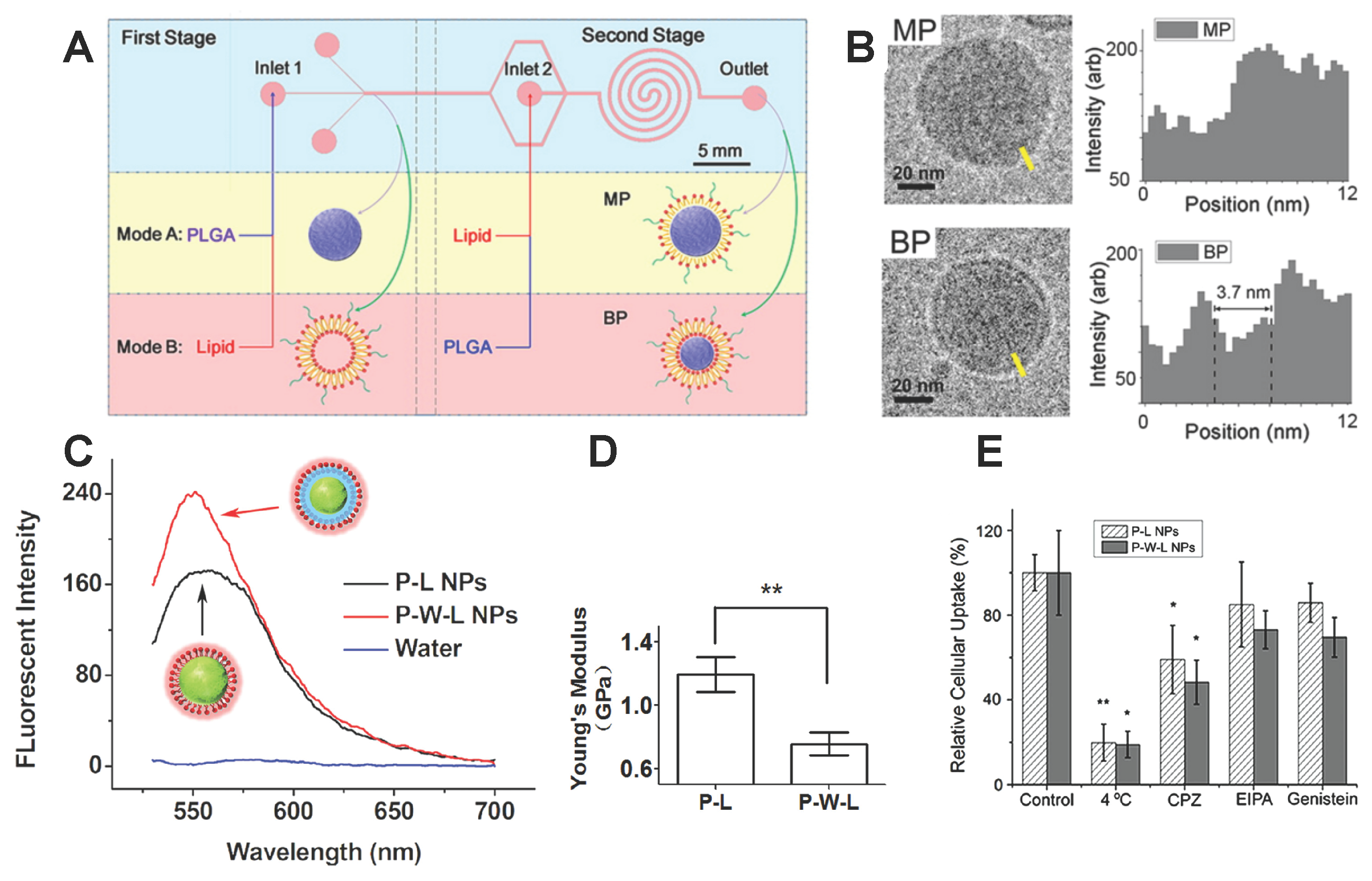
2.2. Lipid Molecule-Decorated NPs
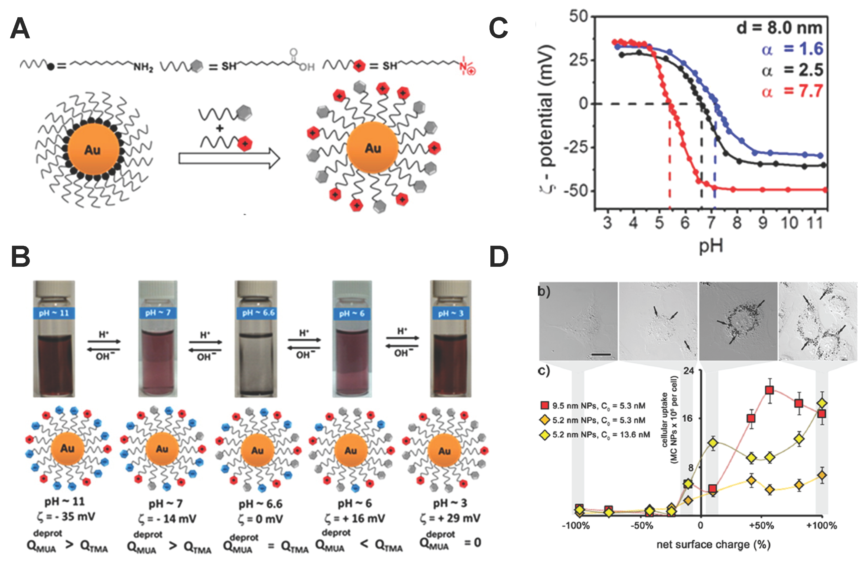
2.3. pH-Responsive Polymer-Decorated NPs
3. Computational Studies
3.1. Amphiphilic Polymer-Decorated NPs
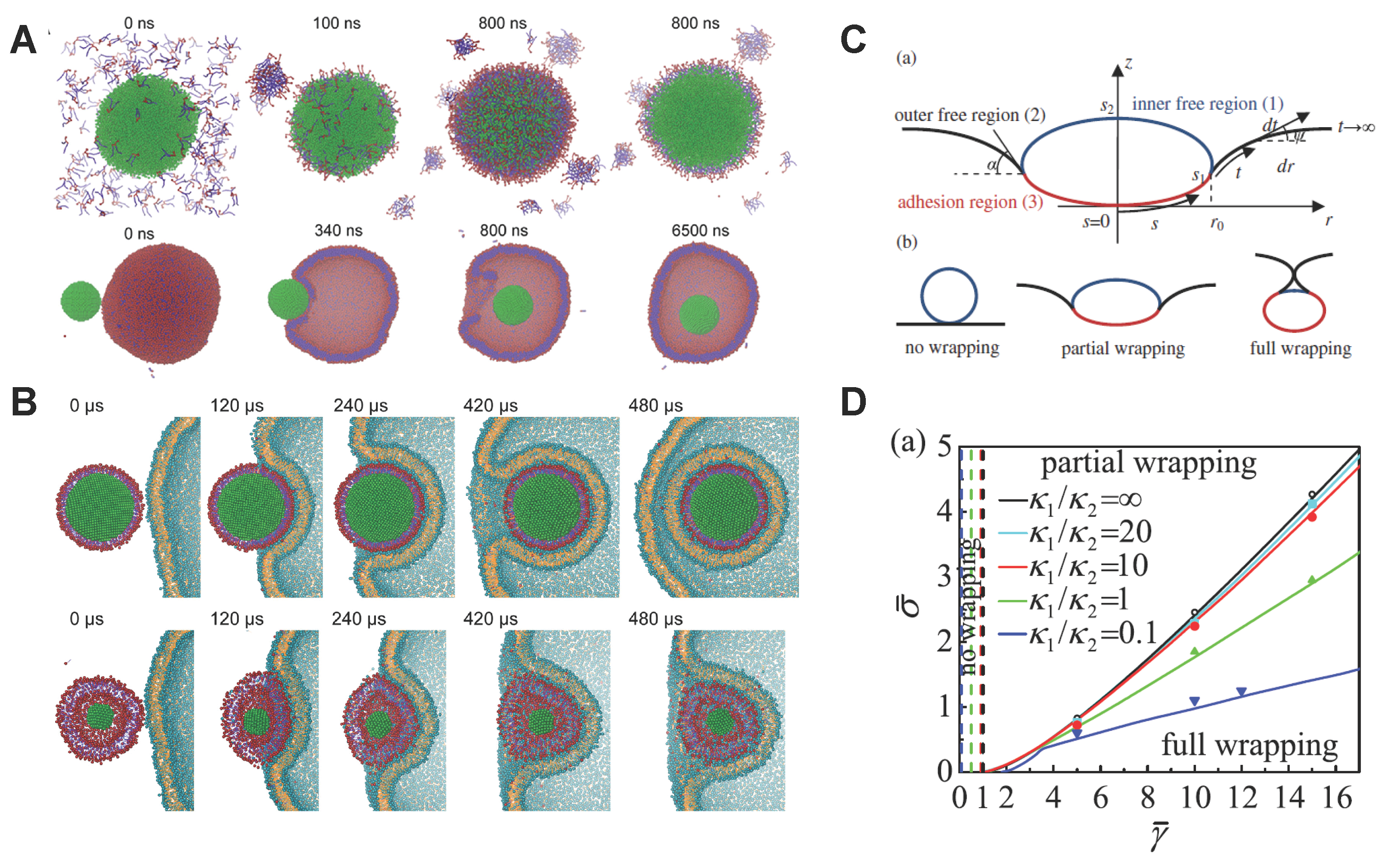
3.2. Lipid Molecule-Decorated NPs
3.3. PEGylated NPs
4. Conclusion and Perspective
Acknowledgments
Author Contributions
Conflicts of Interest
References
- Langer, R. Drug delivery and targeting. Nature 1998, 392, 5–10. [Google Scholar] [PubMed]
- Langer, R.; Tirrell, D.A. Designing materials for biology and medicine. Nature 2004, 428, 487–492. [Google Scholar] [CrossRef] [PubMed]
- Peer, D.; Karp, J.M.; Hong, S.; Farokhzad, O.C.; Margalit, R.; Langer, R. Nanocarriers as an emerging platform for cancer therapy. Nat. Nanotechnol. 2007, 2, 751–760. [Google Scholar] [CrossRef] [PubMed]
- Zhang, L.; Gu, F.; Chan, J.; Wang, A.; Langer, R.; Farokhzad, O. Nanoparticles in medicine: Therapeutic applications and developments. Clin. Pharmacol. Ther. 2008, 83, 761–769. [Google Scholar] [CrossRef] [PubMed]
- Ferrari, M. Nanovector therapeutics. Curr. Opin. Chem. Biol. 2005, 9, 343–346. [Google Scholar] [CrossRef] [PubMed]
- Elwing, H. Protein absorption and ellipsometry in biomaterial research. Biomaterials 1998, 19, 397–406. [Google Scholar] [CrossRef]
- Aderem, A.; Underhill, D.M. Mechanisms of phagocytosis in macrophages. Annu. Rev. Immunol. 1999, 17, 593–623. [Google Scholar] [CrossRef] [PubMed]
- Gref, R.; Minamitake, Y.; Peracchia, M.T.; Trubetskoy, V.; Torchilin, V.; Langer, R. Biodegradable long-circulating polymeric nanospheres. Science 1994, 263, 1600–1603. [Google Scholar] [CrossRef] [PubMed]
- Uhrich, K.E.; Cannizzaro, S.M.; Langer, R.S.; Shakesheff, K.M. Polymeric systems for controlled drug release. Chem. Rev. 1999, 99, 3181–3198. [Google Scholar] [CrossRef] [PubMed]
- Farokhzad, O.C.; Cheng, J.; Teply, B.A.; Sherifi, I.; Jon, S.; Kantoff, P.W.; Richie, J.P.; Langer, R. Targeted nanoparticle-aptamer bioconjugates for cancer chemotherapy in vivo. Proc. Natl. Acad. Sci. USA 2006, 103, 6315–6320. [Google Scholar] [CrossRef] [PubMed]
- Chou, L.Y.; Ming, K.; Chan, W.C. Strategies for the intracellular delivery of nanoparticles. Chem. Soc. Rev. 2011, 40, 233–245. [Google Scholar] [CrossRef] [PubMed]
- Li, Y.; Stroberg, W.; Lee, T.R.; Kim, H.S.; Man, H.; Ho, D.; Decuzzi, P.; Liu, W.K. Multiscale modeling and uncertainty quantification in nanoparticle-mediated drug/gene delivery. Comput. Mech. 2014, 53, 511–537. [Google Scholar] [CrossRef]
- Li, Y.; Lian, Y.; Zhang, L.T.; Aldousari, S.M.; Hedia, H.S.; Asiri, S.A.; Liu, W.K. Cell and nanoparticle transport in tumour microvasculature: The role of size, shape and surface functionality of nanoparticles. Interface Focus 2016, 6, 20150086. [Google Scholar] [CrossRef] [PubMed]
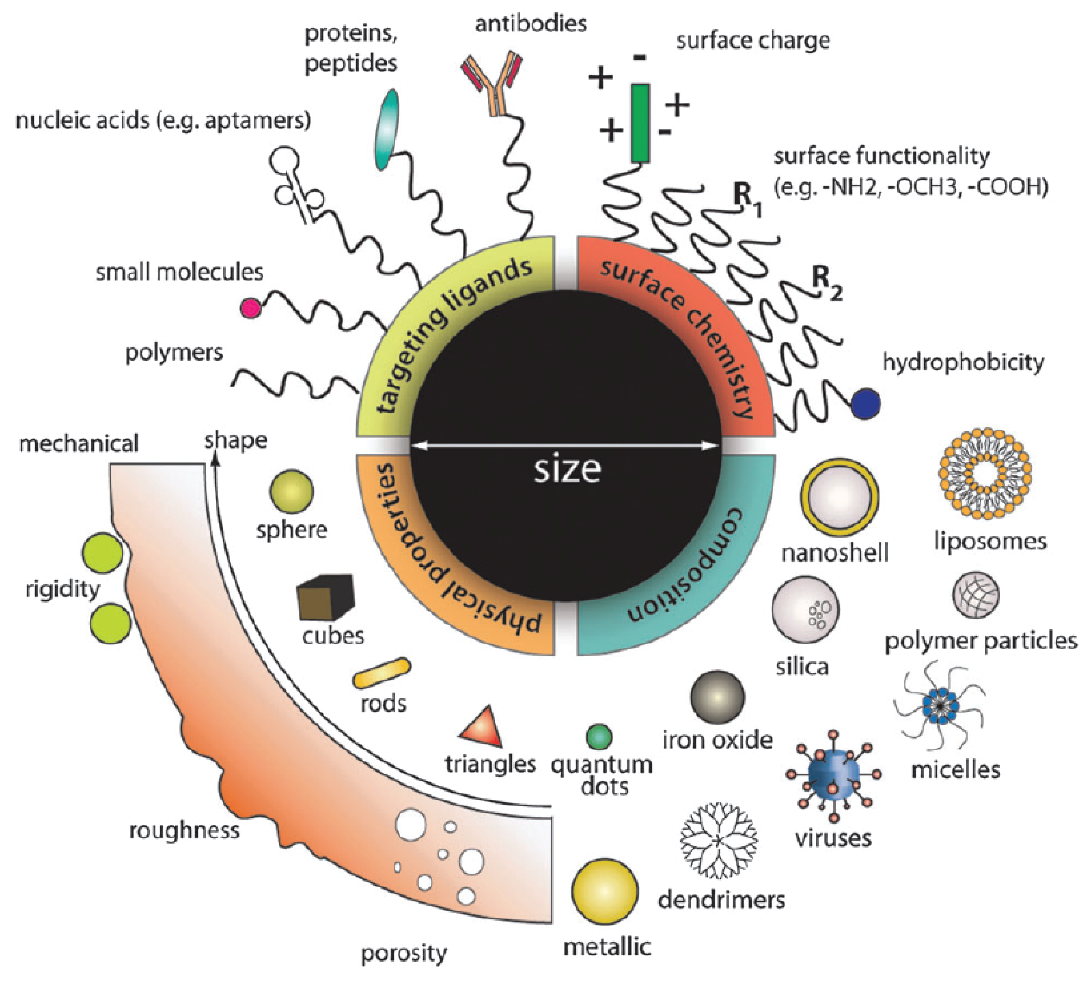
- Albanese, A.; Tang, P.S.; Chan, W.C. The effect of nanoparticle size, shape, and surface chemistry on biological systems. Annu. Rev. Biomed. Eng. 2012, 14, 1–16. [Google Scholar] [CrossRef] [PubMed]
- Petros, R.A.; DeSimone, J.M. Strategies in the design of nanoparticles for therapeutic applications. Nat. Rev. Drug Discov. 2010, 9, 615–627. [Google Scholar] [CrossRef] [PubMed]
- Bao, G.; Bazilevs, Y.; Chung, J.H.; Decuzzi, P.; Espinosa, H.D.; Ferrari, M.; Gao, H.; Hossain, S.S.; Hughes, T.J.; Kamm, R.D.A. USNCTAM perspectives on mechanics in medicine. J. R. Soc. Interface 2014, 11, 20140301. [Google Scholar] [CrossRef] [PubMed]
- Decuzzi, P.; Pasqualini, R.; Arap, W.; Ferrari, M. Intravascular delivery of particulate systems: Does geometry really matter? Pharm. Res. 2009, 26, 235–243. [Google Scholar] [CrossRef] [PubMed]
- Decuzzi, P.; Ferrari, M. Design maps for nanoparticles targeting the diseased microvasculature. Biomaterials 2008, 29, 377–384. [Google Scholar] [CrossRef] [PubMed]
- Immordino, M.L.; Dosio, F.; Cattel, L. Stealth liposomes: Review of the basic science, rationale, and clinical applications, existing and potential. Int. J. Nanomed. 2006, 1, 297–315. [Google Scholar]
- Molineux, G. Pegylation: Engineering improved pharmaceuticals for enhanced therapy. Cancer Treat. Rev. 2002, 28, 13–16. [Google Scholar] [CrossRef]
- Walkey, C.D.; Olsen, J.B.; Guo, H.; Emili, A.; Chan, W.C. Nanoparticle size and surface chemistry determine serum protein adsorption and macrophage uptake. J. Am. Chem. Soc. 2012, 134, 2139–2147. [Google Scholar] [CrossRef] [PubMed]
- Pelaz, B.; del Pino, P.; Maffre, P.; Hartmann, R.; Gallego, M.; Rivera-Fernández, S.; de la Fuente, J.M.; Nienhaus, G.U.; Parak, W.J. Surface functionalization of nanoparticles with polyethylene glycol: Effects on protein adsorption and cellular uptake. ACS Nano 2015, 9, 6996–7008. [Google Scholar] [CrossRef] [PubMed]
- Perrault, S.D.; Walkey, C.; Jennings, T.; Fischer, H.C.; Chan, W.C. Mediating tumor targeting efficiency of nanoparticles through design. Nano Lett. 2009, 9, 1909–1915. [Google Scholar] [CrossRef] [PubMed]
- Otsuka, H.; Nagasaki, Y.; Kataoka, K. PEGylated nanoparticles for biological and pharmaceutical applications. Adv. Drug Deliv. Rev. 2012, 64, 246–255. [Google Scholar] [CrossRef]
- Lipka, J.; Semmler-Behnke, M.; Sperling, R.A.; Wenk, A.; Takenaka, S.; Schleh, C.; Kissel, T.; Parak, W.J.; Kreyling, W.G. Biodistribution of PEG-modified gold nanoparticles following intratracheal instillation and intravenous injection. Biomaterials 2010, 31, 6574–6581. [Google Scholar] [CrossRef] [PubMed]
- Weissig, V.; Whiteman, K.R.; Torchilin, V.P. Accumulation of protein-loaded long-circulating micelles and liposomes in subcutaneous Lewis lung carcinoma in mice. Pharm. Res. 1998, 15, 1552–1556. [Google Scholar] [CrossRef] [PubMed]
- Savić, R.; Luo, L.; Eisenberg, A.; Maysinger, D. Micellar nanocontainers distribute to defined cytoplasmic organelles. Science 2003, 300, 615–618. [Google Scholar] [CrossRef] [PubMed]
- Poon, Z.; Chang, D.; Zhao, X.; Hammond, P.T. Layer-by-layer nanoparticles with a pH-sheddable layer for in vivo targeting of tumor hypoxia. ACS Nano 2011, 5, 4284–4292. [Google Scholar] [CrossRef] [PubMed]
- Zhang, S.; Gao, H.; Bao, G. Physical principles of nanoparticle cellular endocytosis. ACS Nano 2015, 9, 8655–8671. [Google Scholar] [CrossRef] [PubMed]
- Gonzalez Solveyra, E.; Szleifer, I. What is the role of curvature on the properties of nanomaterials for biomedical applications? Wiley Interdiscip. Rev. Nanomed. Nanobiotechnol. 2015. [Google Scholar] [CrossRef] [PubMed]
- Ding, H.M.; Ma, Y.Q. Theoretical and computational investigations of nanoparticle-biomembrane interactions in cellular delivery. Small 2015, 11, 1055–1071. [Google Scholar] [CrossRef] [PubMed]
- Doherty, G.J.; McMahon, H.T. Mechanisms of endocytosis. Annu. Rev. Biochem. 2009, 78, 857–902. [Google Scholar] [CrossRef] [PubMed]
- Zhang, L.; Becton, M.; Wang, X. Designing nanoparticle translocation through cell membranes by varying amphiphilic polymer coatings. J. Phys. Chem. B 2015, 119, 3786–3794. [Google Scholar] [CrossRef] [PubMed]
- Zhang, L.; Wang, X. Coarse-grained modeling of vesicle responses to active rotational nanoparticles. Nanoscale 2015, 7, 13458–13467. [Google Scholar] [CrossRef] [PubMed]
- Colombo, M.; Carregal-Romero, S.; Casula, M.F.; Gutierrez, L.; Morales, M.P.; Boehm, I.B.; Heverhagen, J.T.; Prosperi, D.; Parak, W.J. Biological applications of magnetic nanoparticles. Chem. Soc. Rev. 2012, 41, 4306–4334. [Google Scholar] [CrossRef] [PubMed]
- N’Guyen, T.T.; Duong, H.T.; Basuki, J.; Montembault, V.; Pascual, S.; Guibert, C.; Fresnais, J.; Boyer, C.; Whittaker, M.R.; Davis, T.P.; et al. Functional iron oxide magnetic nanoparticles with hyperthermia-induced drug release ability by using a combination of orthogonal click reactions. Angew. Chem. Int. Ed. 2013, 52, 14152–14156. [Google Scholar] [CrossRef] [PubMed]
- Carregal-Romero, S.; Guardia, P.; Yu, X.; Hartmann, R.; Pellegrino, T.; Parak, W.J. Magnetically triggered release of molecular cargo from iron oxide nanoparticle loaded microcapsules. Nanoscale 2015, 7, 570–576. [Google Scholar] [CrossRef] [PubMed]
- Arosio, P.; Thévenot, J.; Orlando, T.; Orsini, F.; Corti, M.; Mariani, M.; Bordonali, L.; Innocenti, C.; Sangregorio, C.; Oliveira, H.; et al. Hybrid iron oxide-copolymer micelles and vesicles as contrast agents for MRI: Impact of the nanostructure on the relaxometric properties. J. Mater. Chem. B 2013, 1, 5317–5328. [Google Scholar] [CrossRef]
- Fantechi, E.; Innocenti, C.; Zanardelli, M.; Fittipaldi, M.; Falvo, E.; Carbo, M.; Shullani, V.; di Cesare Mannelli, L.; Ghelardini, C.; Ferretti, A.M.; et al. A smart platform for hyperthermia application in cancer treatment: Cobalt-doped ferrite nanoparticles mineralized in human ferritin cages. ACS Nano 2014, 8, 4705–4719. [Google Scholar] [CrossRef] [PubMed]
- Wei, H.; Insin, N.; Lee, J.; Han, H.S.; Cordero, J.M.; Liu, W.; Bawendi, M.G. Compact zwitterion-coated iron oxide nanoparticles for biological applications. Nano Lett. 2011, 12, 22–25. [Google Scholar] [CrossRef] [PubMed]
- Kievit, F.M.; Veiseh, O.; Bhattarai, N.; Fang, C.; Gunn, J.W.; Lee, D.; Ellenbogen, R.G.; Olson, J.M.; Zhang, M. PEI-PEG-chitosan-copolymer-coated iron oxide nanoparticles for safe gene delivery: Synthesis, complexation, and transfection. Adv. Funct. Mater. 2009, 19, 2244–2251. [Google Scholar] [CrossRef] [PubMed]
- Jiang, S.; Eltoukhy, A.A.; Love, K.T.; Langer, R.; Anderson, D.G. Lipidoid-coated iron oxide nanoparticles for efficient DNA and siRNA delivery. Nano Lett. 2013, 13, 1059–1064. [Google Scholar] [CrossRef] [PubMed]
- Brandenberger, C.; Mühlfeld, C.; Ali, Z.; Lenz, A.G.; Schmid, O.; Parak, W.J.; Gehr, P.; Rothen-Rutishauser, B. Quantitative evaluation of cellular uptake and trafficking of plain and polyethylene glycol-coated gold nanoparticles. Small 2010, 6, 1669–1678. [Google Scholar] [CrossRef] [PubMed]
- Verma, A.; Uzun, O.; Hu, Y.; Hu, Y.; Han, H.S.; Watson, N.; Chen, S.; Irvine, D.J.; Stellacci, F. Surface-structure-regulated cell-membrane penetration by monolayer-protected nanoparticles. Nat. Mater. 2008, 7, 588–595. [Google Scholar] [CrossRef] [PubMed]
- Slowing, I.; Trewyn, B.G.; Lin, V.S.Y. Effect of surface functionalization of MCM-41-type mesoporous silica nanoparticles on the endocytosis by human cancer cells. J. Am. Chem. Soc. 2006, 128, 14792–14793. [Google Scholar] [CrossRef] [PubMed]
- Giljohann, D.A.; Seferos, D.S.; Patel, P.C.; Millstone, J.E.; Rosi, N.L.; Mirkin, C.A. Oligonucleotide loading determines cellular uptake of DNA-modified gold nanoparticles. Nano Lett. 2007, 7, 3818–3821. [Google Scholar] [CrossRef] [PubMed]
- Yang, P.H.; Sun, X.; Chiu, J.F.; Sun, H.; He, Q.Y. Transferrin-mediated gold nanoparticle cellular uptake. Bioconjug. Chem. 2005, 16, 494–496. [Google Scholar] [CrossRef] [PubMed]
- Chithrani, B.D.; Chan, W.C. Elucidating the mechanism of cellular uptake and removal of protein-coated gold nanoparticles of different sizes and shapes. Nano Lett. 2007, 7, 1542–1550. [Google Scholar] [CrossRef] [PubMed]
- Wang, J.; Tian, S.; Petros, R.A.; Napier, M.E.; DeSimone, J.M. The complex role of multivalency in nanoparticles targeting the transferrin receptor for cancer therapies. J. Am. Chem. Soc. 2010, 132, 11306–11313. [Google Scholar] [CrossRef] [PubMed]
- Zhang, L.; Feng, Q.; Wang, J.; Zhang, S.; Ding, B.; Wei, Y.; Dong, M.; Ryu, J.Y.; Yoon, T.Y.; Shi, X.; et al. Microfluidic synthesis of hybrid nanoparticles with controlled lipid layers: Understanding flexibility-regulated cell-nanoparticle interaction. ACS Nano 2015, 9, 9912–9921. [Google Scholar] [CrossRef] [PubMed]
- Sun, J.; Zhang, L.; Wang, J.; Feng, Q.; Liu, D.; Yin, Q.; Xu, D.; Wei, Y.; Ding, B.; Shi, X.; et al. Tunable rigidity of (polymeric core)-lipid shell) nanoparticles for regulated cellular uptake. Adv. Mater. 2015, 27, 1402–1407. [Google Scholar] [CrossRef] [PubMed]
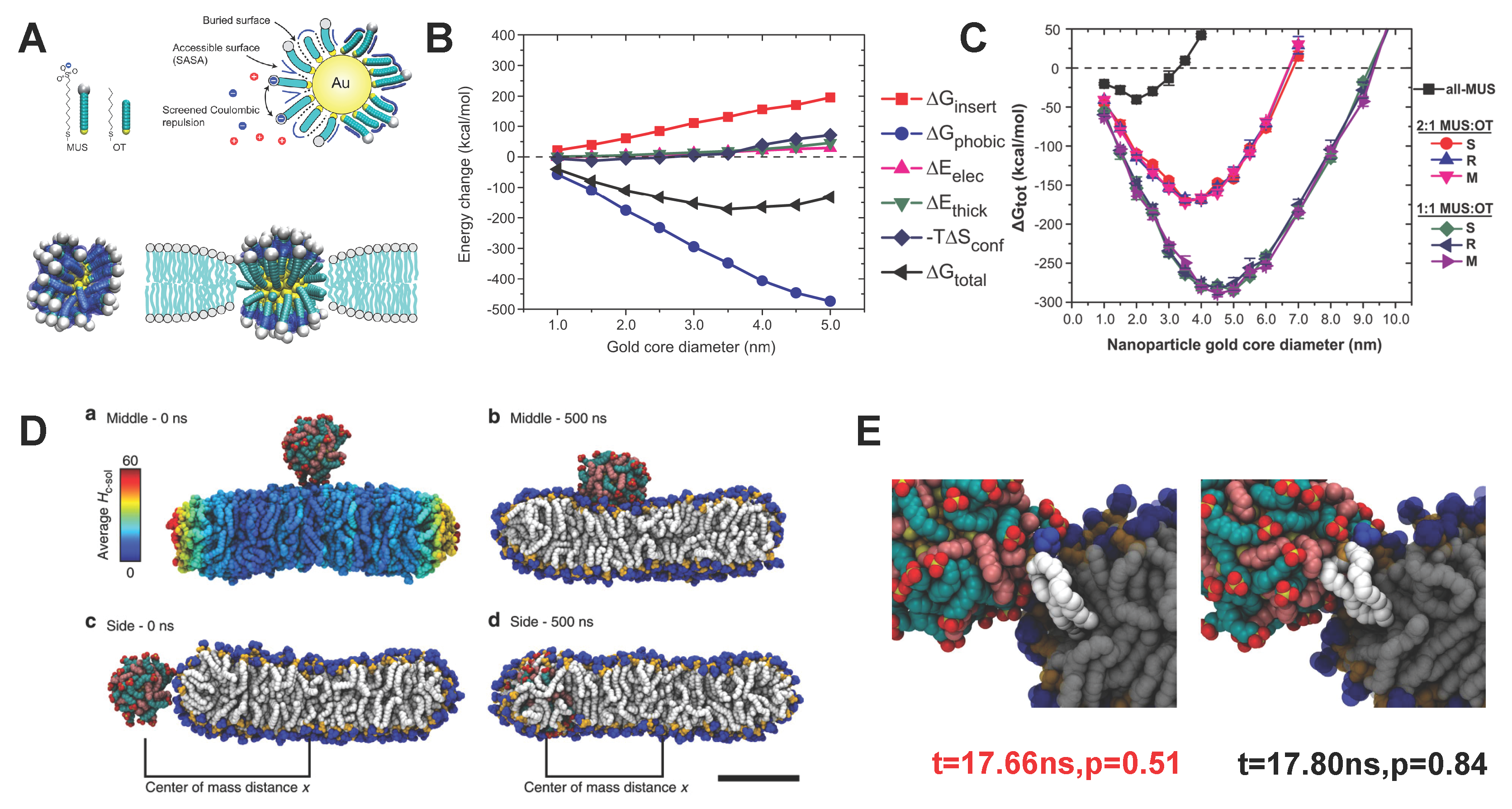
- Van Lehn, R.C.; Atukorale, P.U.; Carney, R.P.; Yang, Y.S.; Stellacci, F.; Irvine, D.J.; Alexander-Katz, A. Effect of particle diameter and surface composition on the spontaneous fusion of monolayer-protected gold nanoparticles with lipid bilayers. Nano Lett. 2013, 13, 4060–4067. [Google Scholar] [CrossRef] [PubMed]
- Chandler, D. Interfaces and the driving force of hydrophobic assembly. Nature 2005, 437, 640–647. [Google Scholar] [CrossRef] [PubMed]
- Van Lehn, R.C.; Alexander-Katz, A. Free energy change for insertion of charged, monolayer-protected nanoparticles into lipid bilayers. Soft Matter 2014, 10, 648–658. [Google Scholar] [CrossRef] [PubMed]
- Pillai, P.P.; Huda, S.; Kowalczyk, B.; Grzybowski, B.A. Controlled pH stability and adjustable cellular uptake of mixed-charge nanoparticles. J. Am. Chem. Soc. 2013, 135, 6392–6395. [Google Scholar] [CrossRef] [PubMed]
- Dorairaj, S.; Allen, T.W. On the thermodynamic stability of a charged arginine side chain in a transmembrane helix. Proc. Natl. Acad. Sci. USA 2007, 104, 4943–4948. [Google Scholar] [CrossRef] [PubMed]
- Van Lehn, R.C.; Alexander-Katz, A. Fusion of ligand-coated nanoparticles with lipid bilayers: Effect of ligand flexibility. J. Phys. Chem. A 2014, 118, 5848–5856. [Google Scholar] [CrossRef] [PubMed]
- Van Lehn, R.C.; Alexander-Katz, A. Pathway for insertion of amphiphilic nanoparticles into defect-free lipid bilayers from atomistic molecular dynamics simulations. Soft Matter 2015, 11, 3165–3175. [Google Scholar] [CrossRef] [PubMed]
- Van Lehn, R.C.; Alexander-Katz, A. Membrane-embedded nanoparticles induce lipid rearrangements similar to those exhibited by biological membrane proteins. J. Phys. Chem. B 2014, 118, 12586–12598. [Google Scholar] [CrossRef] [PubMed]
- Van Lehn, R.C.; Alexander-Katz, A. Ligand-mediated short-range attraction drives aggregation of charged monolayer-protected gold nanoparticles. Langmuir 2013, 29, 8788–8798. [Google Scholar] [CrossRef] [PubMed]
- Van Lehn, R.C.; Alexander-Katz, A. Structure of mixed-monolayer-protected nanoparticles in aqueous salt solution from atomistic molecular dynamics simulations. J. Phys. Chem. C 2013, 117, 20104–20115. [Google Scholar] [CrossRef]
- Simonelli, F.; Bochicchio, D.; Ferrando, R.; Rossi, G. Monolayer-protected anionic Au nanoparticles walk into lipid membranes step by step. J. Phys. Chem. Lett. 2015, 6, 3175–3179. [Google Scholar] [CrossRef]
- Van Lehn, R.C.; Ricci, M.; Silva, P.H.; Andreozzi, P.; Reguera, J.; VoĀŕtchovsky, K.; Stellacci, F.; Alexander-Katz, A. Lipid tail protrusions mediate the insertion of nanoparticles into model cell membranes. Nat. Commun. 2014, 5, 4482. [Google Scholar] [CrossRef] [PubMed] [Green Version]
- Yi, X.; Shi, X.; Gao, H. Cellular uptake of elastic nanoparticles. Phys. Rev. Lett. 2011, 107, 098101. [Google Scholar] [CrossRef] [PubMed]
- Li, Y.; Kröger, M.; Liu, W.K. Endocytosis of PEGylated nanoparticles accompanied by structural and free energy changes of the grafted polyethylene glycol. Biomaterials 2014, 35, 8467–8478. [Google Scholar] [CrossRef] [PubMed]
- Li, Y.; Kröger, M.; Liu, W.K. Shape effect in cellular uptake of pegylated nanoparticles: Comparison between sphere, rod, cube and disk. Nanoscale 2015, 7, 16631–16646. [Google Scholar] [CrossRef] [PubMed]
- Lee, H.; de Vries, A.H.; Marrink, S.J.; Pastor, R.W. A coarse-grained model for polyethylene oxide and polyethylene glycol: Conformation and hydrodynamics. J. Phys. Chem. B 2009, 113, 13186–13194. [Google Scholar] [CrossRef] [PubMed]
- Li, Y.; Abberton, B.C.; Kröger, M.; Liu, W.K. Challenges in multiscale modeling of polymer dynamics. Polymers 2013, 5, 751–832. [Google Scholar] [CrossRef]
- Halperin, A.; Kroger, M.; Zhulina, E. Colloid-brush interactions: The effect of solvent quality. Macromolecules 2011, 44, 3622–3638. [Google Scholar] [CrossRef]
- Wijmans, C.; Zhulina, E.B. Polymer brushes at curved surfaces. Macromolecules 1993, 26, 7214–7224. [Google Scholar] [CrossRef]
- Scheutjens, J.; Fleer, G. Statistical theory of the adsorption of interacting chain molecules. 1. Partition function, segment density distribution, and adsorption isotherms. J. Phys. Chem. 1979, 83, 1619–1635. [Google Scholar] [CrossRef]
- Hao, N.; Li, L.; Zhang, Q.; Huang, X.; Meng, X.; Zhang, Y.; Chen, D.; Tang, F.; Li, L. The shape effect of PEGylated mesoporous silica nanoparticles on cellular uptake pathway in Hela cells. Microporous Mesoporous Mater. 2012, 162, 14–23. [Google Scholar] [CrossRef]
- Kim, H.; Leal, C. Cuboplexes: Topologically active siRNA delivery. ACS Nano 2015, 9, 10214–10226. [Google Scholar] [CrossRef] [PubMed]
- Sharma, G.; Valenta, D.T.; Altman, Y.; Harvey, S.; Xie, H.; Mitragotri, S.; Smith, J.W. Polymer particle shape independently influences binding and internalization by macrophages. J. Control. Release 2010, 147, 408–412. [Google Scholar] [CrossRef] [PubMed]
- Barua, S.; Yoo, J.W.; Kolhar, P.; Wakankar, A.; Gokarn, Y.R.; Mitragotri, S. Particle shape enhances specificity of antibody-displaying nanoparticles. Proc. Natl. Acad. Sci. USA 2013, 110, 3270–3275. [Google Scholar] [CrossRef] [PubMed]
- Agarwal, R.; Singh, V.; Jurney, P.; Shi, L.; Sreenivasan, S.; Roy, K. Mammalian cells preferentially internalize hydrogel nanodiscs over nanorods and use shape-specific uptake mechanisms. Proc. Natl. Acad. Sci. USA 2013, 110, 17247–17252. [Google Scholar] [CrossRef] [PubMed]
- Truong, N.P.; Whittaker, M.R.; Mak, C.W.; Davis, T.P. The importance of nanoparticle shape in cancer drug delivery. Expert Opin. Drug Deliv. 2015, 12, 129–142. [Google Scholar] [CrossRef] [PubMed]
- Tasciotti, E.; Liu, X.; Bhavane, R.; Plant, K.; Leonard, A.D.; Price, B.K.; Cheng, M.M.C.; Decuzzi, P.; Tour, J.M.; Robertson, F.; et al. Mesoporous silicon particles as a multistage delivery system for imaging and therapeutic applications. Nat. Nanotechnol. 2008, 3, 151–157. [Google Scholar] [CrossRef] [PubMed]
- Lee, T.R.; Choi, M.; Kopacz, A.M.; Yun, S.H.; Liu, W.K.; Decuzzi, P. On the near-wall accumulation of injectable particles in the microcirculation: Smaller is not better. Sci. Rep. 2013, 3, 2079. [Google Scholar] [CrossRef] [PubMed]
- Aoyama, Y.; Kanamori, T.; Nakai, T.; Sasaki, T.; Horiuchi, S.; Sando, S.; Niidome, T. Artificial viruses and their application to gene delivery. Size-controlled gene coating with glycocluster nanoparticles. J. Am. Chem. Soc. 2003, 125, 3455–3457. [Google Scholar] [CrossRef] [PubMed]
- Osaki, F.; Kanamori, T.; Sando, S.; Sera, T.; Aoyama, Y. A quantum dot conjugated sugar ball and its cellular uptake. On the size effects of endocytosis in the subviral region. J. Am. Chem. Soc. 2004, 126, 6520–6521. [Google Scholar] [CrossRef] [PubMed]
- Choi, H.S.; Liu, W.; Liu, F.; Nasr, K.; Misra, P.; Bawendi, M.G.; Frangioni, J.V. Design considerations for tumour-targeted nanoparticles. Nat. Nanotechnol. 2010, 5, 42–47. [Google Scholar] [CrossRef] [PubMed] [Green Version]
- Chou, L.Y.; Zagorovsky, K.; Chan, W.C. DNA assembly of nanoparticle superstructures for controlled biological delivery and elimination. Nat. Nanotechnol. 2014, 9, 148–155. [Google Scholar] [CrossRef] [PubMed]


| Category | Surface | Core | Key Observation | References |
|---|---|---|---|---|
| Polymer | PEG * | Au *, liposome | Long blood-circulation time, different celluar uptake pathway | [19,23,43] |
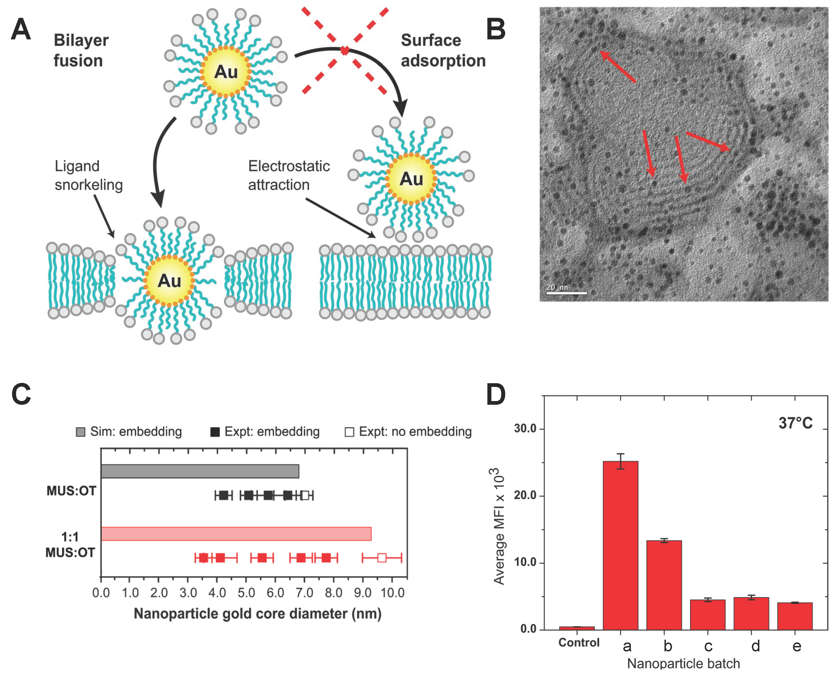
| Polymer | MUS *, OT * | Au | Direct penetration without membrane disruption | [44] |
| Polymer | AP *, GP *, GEGP *, FAP * | MS * | Surface charge related cellular uptake efficiency | [45] |
| Polymer | ZDS * | SPIO | High stability, reduced nonspecific affinity | [40] |
| Copolymer | CP-PEI * | SPIO * | High efficiency in DNA delivery | [41] |
| DNA | Oligonucleotide | Au | High efficiency in cellular uptake mediated by absorbed protein | [46] |
| Protein | Transferrin | Au | Clathrin-mediated endocytosis pathway and non-toxicity | [47,48,49] |
| Lipid | Various lipids | SPIO | High stability and drug capacity, good cellular uptake | [42] |
| Lipid | DPPC * | PLGA * | Cellular uptake depends on the core–shell structure | [50,51] |
© 2016 by the authors. Licensee MDPI, Basel, Switzerland. This article is an open access article distributed under the terms and conditions of the Creative Commons by Attribution (CC-BY) license ( http://creativecommons.org/licenses/by/4.0/).
Share and Cite
Shen, Z.; Nieh, M.-P.; Li, Y. Decorating Nanoparticle Surface for Targeted Drug Delivery: Opportunities and Challenges. Polymers 2016, 8, 83. https://doi.org/10.3390/polym8030083
Shen Z, Nieh M-P, Li Y. Decorating Nanoparticle Surface for Targeted Drug Delivery: Opportunities and Challenges. Polymers. 2016; 8(3):83. https://doi.org/10.3390/polym8030083
Chicago/Turabian StyleShen, Zhiqiang, Mu-Ping Nieh, and Ying Li. 2016. "Decorating Nanoparticle Surface for Targeted Drug Delivery: Opportunities and Challenges" Polymers 8, no. 3: 83. https://doi.org/10.3390/polym8030083