Article

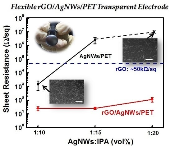
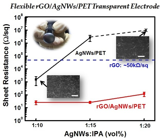
Flexible Transparent Electrode of Hybrid Ag-Nanowire/Reduced-Graphene-Oxide Thin Film on PET Substrate Prepared Using H2/Ar Low-Damage Plasma

1
Department of Materials Engineering, Ming Chi University of Technology, 84 Gungjuan Rd., Taishan Dist., New Taipei City 243, Taiwan
2
Material and Chemical Research Laboratories, Industrial Technology Research Institute, 195, Sec. 4, Chung Hsin Rd., Chutung, Hsinchu 300, Taiwan
*
Author to whom correspondence should be addressed.
Polymers 2017, 9(1), 28; https://doi.org/10.3390/polym9010028
Submission received: 11 November 2016 / Revised: 5 January 2017 / Accepted: 10 January 2017 / Published: 13 January 2017
(This article belongs to the Special Issue Functionally Responsive Polymeric Materials)

Abstract

:
We employ H2/Ar low-damage plasma treatment (H2/Ar-LDPT) to reduce graphene oxide (GO) coating on a polymer substrate—polyethylene terephthalate (PET)—with the assistance of atomic hydrogen (Hα) at low temperature of 70 °C. Four-point probing and ultraviolet-visible (UV-Vis) spectroscopy demonstrate that the conductivity and transmittance can be controlled by varying the H2/Ar flow rate, treatment time, and radio-frequency (RF) power. Optical emission spectroscopy reveals that the Hα intensity depends on these processing parameters, which influence the removal of oxidative functional groups (confirmed via X-ray photoelectron spectroscopy) to yield reduced GO (rGO). To further improve the conductivity while maintaining high transmittance, we introduce silver nanowires (AgNWs) between rGO and a PET substrate to obtain a hybrid rGO/AgNWs/PET with a sheet resistance of ~100 Ω/sq and 81% transmittance. In addition, the hybrid rGO/AgNWs thin film also shows high flexibility and durability and is suitable for flexible and wearable electronics applications.

Graphical Abstract

1. Introduction

Polyethylene terephthalate (PET) is a thermoplastic polyester resin and widely used in food and packaging industries [1,2]. Recently, the demands for wearable and flexible electronics applications, such as solar cells and displays are drastically increasing, PET is becoming a favorite polymer for such electronics applications due to its flexibility, light weight, high transparency and low cost. For the electronics applications, indium tin oxide (ITO), a transparent conductive oxide (TCO), is deposited onto PET substrate commercially as a transparent electrode owing to its conductivity and transparency in the visible range. However, ITO has some drawbacks, including high production costs, supply shortage and brittleness, which would restrict its application in flexible and wearable electronics.
As a result of its excellent optical transparency, flexibility and electrical conductivity, graphene has attracted research attention related to the development of transparent electrodes on flexible substrates. Such devices can be employed in various applications, including solar cells, touch panels, organic light emitting diodes, and wearable electronics [3,4,5,6]. Many graphene preparation methods have been developed, including micromechanical exfoliation of highly oriented pyrolytic graphite [7], sublimation of silicon from silicon carbide [8], and chemical vapor deposition from a carbon-containing gas [9].
Graphene oxide (GO), a derivative of graphene, is a promising alternative for the mass production of graphene-based materials because it can be synthesized in large quantities from inexpensive graphite and is soluble in various solvents. The preparation of a dispersed form of graphene for use in flexible electronic devices is attractive because this material is low cost and solution-processable. However, GO is almost insulating, due to the presence of oxidative functional groups. Therefore, the removal of these groups is necessary in order to convert GO into reduced graphene oxide (rGO). Typically, a chemical method with various reducing agents such as hydrazine, sodium borohydride, and hydroiodic acid, along with vitamin C, glucose, and alkali, is used to reduce GO [10,11,12,13,14,15]. However, chemical reducing agents are harmful to the environment and enable unexpected introduction of heteroatoms into rGO. In addition, such chemical methods are time-consuming and generally ineffective. Further, an additional post-annealing process at 500–1100 °C is required [16,17,18]. Although an annealing process in an Ar or H2 environment has been demonstrated to be an effective reduction method [19,20], the flexible PET substrate cannot withstand such high temperature.
Compared with the methods previously reported in the literature, plasma is environmentally friendly and has a short reducing time as part of a low-temperature process with a high-purity environment. For GO reduction, the generation of atomic hydrogen (Hα) enables effective removal of the oxidative functional groups. However, it has been reported that both the ions and vacuum ultraviolet (VUV) radiation in plasma can break the graphene lattice and destroy the honeycomb-like carbon (C) nanostructure with ease, because their energies are higher than the C–C bond energies of sp2-hybridized C atoms in graphene [21,22,23,24]. As a result, the etching rate is generally too fast to allow precise control over the degree of reduction. Although downstream plasma treatment can be performed to reduce GO without ion bombardment, the resultant material remains sensitive to VUV radiation [25]. The high-intensity VUV radiation generated in a plasma system can greatly enhance the etching rate [26].
In our previous studies, we developed a low-damage plasma treatment (LDPT) method for the functionalization of nanocrystalline and thin-film materials for applications in flash memory devices and ion sensors, respectively [27,28]. Both results demonstrated successful functionalization with minimal plasma damage. By inserting a complementary filter into a parallel-plate plasma system, the ions and higher-energy VUV can be efficiently blocked. Thus, only radicals with extremely low kinetic energy, which have the highest reactivity among the plasma-generated species, can diffuse through the filter and reach the nanomaterials, gently functionalizing them. We have also employed this apparatus to oxidize graphene sheets without ions or VUV radiation; this oxidization could be conducted in a highly controllable manner [29,30]. Although Lee et al. reported remote hydrogen plasma at atmospheric pressure to avoid ion bombardment, in-situ annealing was required to obtain low sheet resistance of rGO [31]. In addition, utilization of hydrogen gas at atmospheric pressure is not a safe process.
In this study, an H2/Ar mixture gas is introduced into the LDPT apparatus, because the hydrogen radicals can be enhanced by Ar via penning ionization [32]. We systematically investigate the sheet resistance and transmittance of the obtained rGO, which is coated on a polyethylene terephthalate (PET) substrate, as functions of the H2/Ar ratio, treatment time, and plasma power. It is reported that silver nanowires (AgNWs) networks, which can be also prepared by low-cost solution-based process compatible with rGO preparation, exhibit high conductivity, high optical transmittance, and good mechanical flexibility [33,34]. However the large roughness of AgNWs and easy oxidation inhibit their applications [35,36]. In this study, we also investigated the introduction of AgNWs between the flexible substrate and rGO, so as to fabricate hybrid rGO/AgNWs thin films. In such a sample structure, the rGO can drastically lower the roughness of AgNWs, and the overall conductivity can be greatly improved while maintaining high transparency.

2. Materials and Methods

2.1. Sample Preparation

GO solution was purchased from Graphenea Inc., San Sebastián, Spain. The GO was dispersed in deionized (DI) water with a 4-mg/mL concentration. The GO was diluted using isopropanol (IPA) and then coated on an optical grade PET substrate (Nan Ya Plastics, BH215, New Taipei City, Taiwan) via spin-coating with 1000-rpm spin speed for 30 s to form GO sheets. Hereafter, these prepared samples are labeled “GO/PET.” Subsequently, the GO/PET was baked to remove the solvent thoroughly using a hot plate at 60 °C for 10 min. The thickness of as-prepared GO film was about 30 nm measured by atomic force microscope. The details were described in Supplementary Materials Figure S1. In addition, AgNWs were purchased from Sigma-Aldrich, Saint Louis, MO, USA (average diameter: 35 μm; length: 115 μm). The AgNWs were dispersed in IPA with a 0.5 wt % concentration. Before being coated onto PET substrate via drop casting, which was followed by drying at 60 °C for 30 min, the AgNWs were also diluted in IPA at various concentrations. This AgNW/IPA solution was then coated on the PET followed by the GO coating under the same conditions as those used for the GO/PET samples. The prepared samples, hereafter, are referred to as GO/AgNWs/PETs.

2.2. Low-Damage H2/Ar Plasma Treatment (H2/Ar-LDPT)

The reduction process to form rGO/PETs was performed using H2/Ar-LDPT. The plasma of LDPT was generated by an inductively coupled plasma system (see Supplementary Materials Figure S2a). The GO/PET samples were loaded onto the lower electrode beneath the grounded complementary filter and at a distance of 2 cm. The filter consists of upper and lower plates separated by a spacer (see Supplementary Materials Figure S2b). Both plates contain many stripes and slits of the same width. The slits on the upper plate are aligned with the stripes on the lower plate, which can block high-energy collimated ions and prevent direct exposure of the samples to UV radiation. In our previous study [27,28], we confirmed that the UV intensity can be reduced by more than 95%. Therefore, the filter can efficiently shield the samples from plasma damage caused by energetic ions and UV radiation. The filter only permits neutral and reactive radicals to diffuse through and reach the heated substrate, thus realizing a low-damage treatment process. The processing conditions included plasma generation via radio-frequency (RF) power, a 70 °C substrate temperature, and 0.3-Torr pressure. The H2/Ar ratio, treatment time, and RF power were varied in order to investigate their GO reduction ability. The generation of Hα in the plasma was confirmed via optical emission spectroscopy (OES), which was conducted through the vacuum-chamber view port. Note that OES is a powerful instrument for characterization of the excited states in a plasma environment.

2.3. Characterization of rGO and Hybrid rGO/AgNW Thin Films

After the rGO sheet preparation using H2/Ar-LDPT, the sheet resistance and transmittance were investigated using a four-point probe and ultraviolet-visible (UV-Vis) spectroscopy (V-670 UV-Vis-NIR spectrophotometer, JASCO, Tokyo, Japan). The transmittance of the PET substrate used in this study was 90%. The chemical compositions of the rGO sheets were examined using X-ray photoelectron spectroscopy (XPS; VG ESCA Scientific Theta Probe, Waltham, MA, USA) with a monochromated Al Kα source. Raman spectra were collected using a Horiba Raman system (iHR-550, Kyoto, Japan) with a laser wavelength of 532 nm to investigate the structure of rGO sheets. The Si peak at 520 cm−1 was used as the reference for wavenumber calibration prior to each measurement. A field emission scanning electron microscope (FESEM; JEOL JSM 6701F, Tokyo, Japan) and atomic force microscope (AFM; BRUCKER Dimension Edge, Billerica, MA, USA) were used to study the surface morphologies of AgNW and hybrid thin film.

3. Results and Discussion

Figure 1a shows the H2/Ar plasma spectra obtained for various H2/Ar ratios using OES. For all spectra, dense lines corresponding to Ar can be observed in the 700–800 nm range. A peak is positioned at 656.3 nm for all H2/Ar mixing ratios, which is due to the presence of Hα. From Figure 1b, as the Ar flow rate increases, the Hα intensity increases; this change results from penning ionization [31]. When the Ar flow rate is decreased, corresponding to a H2/Ar ratio of 15/15, the Hα intensity is comparable to that of pure H2 plasma, indicating reduced penning ionization. Accordingly, in what follows, we neglect the pure H2 plasma conditions affecting the rGO characteristics. Figure 1c shows the H2/Ar plasma spectra obtained for various RF powers and a fixed H2/Ar ratio of 10/20. The relative Hα intensity was found to increase with increased RF power as shown in Figure 1d. From the OES results, it is clearly apparent that the H2/Ar ratio and RF power greatly influence the Hα intensity, which is the main species that reduces GO.
Next, we systematically investigated the reduction effect on the GO conductivity and transmittance by varying the Hα intensity and treatment time. The as-coated GO sheet exhibited no conductivity and transmittance of 88.9% at wavelength of 550 nm. Figure 2a shows the sheet resistance trends obtained for different treatment times and H2/Ar ratios at an RF power of 200 W. For all treatment times, the H2/Ar ratio of 5/25 exhibits the lowest sheet resistance. As the Ar flow rate resistance decreases. In particular, in the case of the five-minute treatment time, all the sheet resistances obtained for H2/Ar ratios of 10/20 and 15/15 exceeded the measurement limitation (104 kΩ/sq), as denoted by the “x” symbols in Figure 2a. This was because of the low Hα intensity, which prevented achievement of GO reduction within a short treatment time. In the case of 10-min treatment, the sheet resistance decreases slightly with increased Ar flow rate. This result also corresponds to decreased Hα intensity, as shown in Figure 1b. Furthermore, for the 30-min case, the sheet resistances remained at almost 60 kΩ/sq, regardless of the H2/Ar ratio. This result also suggests that the maximum reduction can be achieved for a sufficiently long treatment, even though the plasma exhibits the lowest Hα intensity under 200-W RF power. It is worth noting that the temperature did not increase during the 30-min treatment, because LDPT is a very low-damage treatment that efficiently eliminates the ion bombardment that induces a temperature increase. Figure 2b shows the sheet resistance depending on the treatment time and H2/Ar ratio at an RF power of 300 W. The result has almost the same trend as that observed in Figure 2a, except for the value obtained for the H2/Ar ratio of 10/20 and five-minute treatment. The sheet resistance of the rGO/PET sample under these conditions was measurable. For the 30-min case, the sheet resistance values also remained at the same level (ca. 50 kΩ/sq) as those obtained for 200-W RF power, for all H2/Ar ratios. Figure 2c shows the sheet resistance for different treatment times and H2/Ar ratios under 400-W RF power. For the five-minute case, the sheet resistance values decreased slightly with increasing Ar flow rate, due to the increase of Hα. On the other hand, the sheet resistances for the 10- and 30-min cases are almost at the same level and are not related to the H2/Ar ratio. This result suggests that the reduction time can be shortened significantly when a high RF power is used. The prepared rGO sheets showed good stability by confirming the variation of sheets resistance as the samples were stored in atmosphere (see Supplementary Materials Figure S3).
The transmittance spectra of GO sheets treated with different treatment times, H2/Ar ratios, and RF powers were recorded by UV-Vis spectrophotometer (see Supplementary Materials Figure S4). The transmittances at 550-nm wavelength for different treatment times and H2/Ar ratios under RF powers of 200, 300 and 400 W are displayed in Figure 3a–c, respectively. For 200-W RF power and all H2/Ar ratios, the transmittances of the rGO/PET samples exhibit low values with increased treatment time. It has been reported that GO absorption is high in the near-infrared range, and that graphene theoretically absorbs 2.3% of visible light at 550 nm [37,38]. Therefore, it is thought that a greater reduction corresponds to a lower transmittance. In other words, a trade-off must be made between conductivity and transmittance. In this study, the lowest transmittance values were observed for 400-W RF power (Figure 3c). The corresponding sheet resistance values were also the lowest.
The oxygen bonding in the rGO sheets after the H2/Ar-LDPT process was examined using XPS. Figure 4a–c show the treatment time, H2/Ar ratio, and RF power dependences of the C 1s spectra, respectively. In addition to nonoxygenated ring carbon (C–C) located at 284.5 eV, the XPS C 1s spectra of the GO sheets feature signals at higher chemical shifts for oxidative functional group, including hydroxyl groups (C–OH), carbonyl groups (C=O), and carboxyl groups (COOH) [29,39]. After the H2/Ar-LDPT process, the intensities of the oxidative functional groups located at the higher chemical shifts decreased, indicating GO reduction. It is also apparent that more oxidative functional groups were removed when the treatment time was longer as shown in Figure 4a. Figure 4b,c show the H2/Ar ratio and RF power dependency on the removal of the oxidative functional groups. As the Ar flow rate and RF power increased, more oxidative functional groups were removed, because of the higher Hα intensity. These results are consistent with those for the sheet resistance and Hα intensity, shown in Figure 1 and Figure 2, respectively, indicating that greater removal of the oxidative functional groups corresponds to a higher reduction level, which, in turn, leads to higher conductivity.
Following the characterization of chemical compositions of GO sheets as a function of various H2/Ar-LDPT process conditions, structural changes to the GO sheets resulting from H2/Ar-LDPT were investigated by Raman spectroscopy. Figure 5a–c displays the Raman spectra of GO sheets treated with different treatment times, H2/Ar ratio, and RF powers. The Raman spectrum of as-coated GO sheet shows a G-band (ca. 1600 cm−1) and D-band (ca. 1350 cm−1) corresponding to ordered sp2 bonded carbon and structural defects created by oxygenated functional groups, respectively [40]. After the H2/Ar-LDPT process, as shown in Figure 5a, the relative intensities of G and D slightly changes as the treatment time increases. The intensity ratio of the D and G bands (I(D)/I(G)) is commonly used as an index for the defect level existing in graphene. As exhibited in Figure 6a, the I(D)/I(G) of as-coated GO sheet is 1.13 and the ratio slightly decreased as the treatment time increased. The I(D)/I(G) is 1.01 for treatment time of 30 min. The dependencies of I(D)/I(G) on H2/Ar ratio and RF power are displayed in Figure 6b,c. As the Ar flow rate and RF power increased, I(D)/I(G) decreased prominently. The lowest values of I(D)/I(G) for Ar flow rate of 25 sccm and RF power of 400 W are 0.94 and 0.89, respectively. Those results indicated that the more the Hα generates in H2/Ar LDPT process, the slightly lower the defect level of rGO sheet is obtained. Moreover, it has been reported that reduction by hydrazine hydrate or hydroiodic acid leads to higher I(D)/I(G) corresponding to the generation of defects [8,9,10]. The decrease in I(D)/I(G) of GO sheets treated by H2/Ar-LDPT indicates that the reduction process slightly repairs the flakes of GO sheets without introducing additional defect due to plasma damage.
In order to further reduce the sheet resistance of the rGO/PET samples while maintaining the relatively high transmittance, we introduced AgNWs between the GO and PET before the H2/Ar-LDPT process. The process conditions used to obtain hybrid rGO/AgNWs thin films on the PET were as follows: RF power: 300 W; H2/Ar ratio: 10/20; treatment time: five minutes. The AgNWs were diluted in IPA in three ratios (AgNWs:IPA): 1:10, 1:15, and 1:20. Figure 7a shows the sheet resistance values of the AgNWs with various dilution ratios. As the diluted solvent (isopropanol (IPA)) content increased, the sheet resistance increased. For the AgNW/IPA ratio of 1:20, the sheet resistance exceeded the measurement limitation. The insets of Figure 7a are SEM images of the AgNW thin films. As the IPA content increased, the AgNW network became coarse, leading to poor conductivity as the connecting points between each AgNW were reduced. After spin-coating GO on the AgNWs and then subjecting them to H2/Ar-LDPT, the sheet resistance values of the resultant rGO/AgNWs/PET samples were almost identical. This result indicates that the AgNWs were embedded into the rGO during spin-coating, which compensated for the discontinuity between each AgNW and yielded considerable enhancement in the conductivity. The transmittance spectra were measured by UV-Vis spectrophotometer (see Supplementary Materials Figure S5). Figure 7b shows the transmittance values of the various rGO/AgNWs/PET samples at wavelength of 550 nm. The sample with the 1:20 dilution ratio exhibited the highest transmittance of 81%. Thus, we obtained hybrid rGO/AgNWs thin films on a flexible PET substrate with high conductivity (~100 Ω/sq) and high transmittance (~81%).
To investigate the influence of H2/Ar-LDPT process on the morphology of the hybrid thin film, SEM and AFM measurements were conducted. Figure 8a shows the top-viewed SEM images of hybrid thin films before (GO/AgNWs) and after (rGO/AgNWs) H2/Ar-LDPT process, respectively. No obvious difference was observed. Figure 8b shows the AFM images of hybrid thin films before and after H2/Ar-LDPT process, respectively. The roughness (Ra) of the hybrid thin film was slightly decreased after H2/Ar-LDPT process.
Finally, the mechanical flexibilities of rGO/AgNW/PET samples were studied by placing them on cylindrical objects with various radii of curvature (Rc). The Rc was estimated by measuring the outer diameter of the objects. In this measurement, the samples were bent to wrap various cylindrical objects, including battery, pen and laser-pointer, and then relaxed for bending cycles of 1, 5, 10 and 100. After each bending cycle, the sheet resistance of rGO/AgNWs/PET was measured. Figure 9 shows the results of sheet resistances of rGO/AgNWs/PET samples after each bending cycles depending on various Rcs of cylindrical objects expressed by Rs/Rs0, where Rs and Rs0 are sheet resistances of before and after bending, respectively. The insets show the photos of rGO/AgNWs/PET wrapping on cylindrical objects with various Rcs. It is clearly seen that the Rs/Rs0 shows no apparent dependence on bending cycle or Rc, and all the values only slightly increases above 1. The results indicate that the morphology of the network of rGOs and AgNWs in hybrid rGO/AgNWs thin film was maintained during the bending test, demonstrating high flexibility and durability.

Supplementary Materials

The supplementary materials are available online at www.mdpi.com/2073-4360/9/1/28/s1.

Acknowledgments

This work was funded by the Ministry of Science and Technology of Taiwan under Grant Number 105-2221-E-131-008.

Author Contributions

Chi-Hsien Huang developed the concept and designed the experiments. Yin-Yin Wang, Tsung-Han Lu and Yen-Cheng Li carried out the experiment and sample characterization. Yin-Yin Wang and Chi-Hsien Huang analyzed the results. Chi-Hsien Huang wrote the manuscript and replied to reviewers’ comments.

Conflicts of Interest

The authors declare no conflict of interest.

References

  1. Baldenegro-Perez, L.A.; Navarro-Rodriguez, D.; Medellin-Rodriguez, F.J.; Hsiao, B.; Avila-Ota, C.A.; Sics, I. Molecular weight and crystallization temperature effects on poly(ethylene terephthalate)(PET) homopolymers, an isothermal crystallization analysis. Polymers 2014, 6, 583–600. [Google Scholar] [CrossRef]
  2. Yue, Q.F.; Xiao, L.F.; Zhang, M.L.; Bai, X.F. The glycolysis of poly(ethylene terephthalate) waste: Lewis acidic ionic liquids as high efficient catalysts. Polymers 2013, 5, 1258–1271. [Google Scholar] [CrossRef]
  3. Dong, L.B.; Xu, C.J.; Huang, Z.H.; Kang, F.Y.; Yang, Q.H.; Zhao, X. Flexible electrodes and supercapacitors for wearable energy storage: A review by category. J. Mater. Chem. A 2016, 4, 4659–4685. [Google Scholar] [CrossRef]
  4. Hang, T.H.; Lee, Y.; Choi, M.R.; Woo, S.H.; Bae, S.H.; Hong, B.H.; Ahn, J.H.; Lee, T.W. Extremely efficient flexible organic light-emitting diodes with modified graphene anode. Nat. Photonics 2012, 6, 105–110. [Google Scholar]
  5. Huang, C.H.; Yu, S.C.; Lai, Y.C.; Chi, G.C.; Yu, P. Efficiency enhancement of organic/GaAs Hybrid photovoltaic cells using transparent graphene as front electrode. IEEE J. Photovol. 2016, 6, 480–485. [Google Scholar] [CrossRef]
  6. Ma, X.Y.; Zhang, H. Fabrication of graphene films with high transparent conducting characteristics. Nanoscale Res. Lett. 2013, 8, 440. [Google Scholar] [CrossRef] [PubMed]
  7. Antonova, I.V.; Mutilin, S.V.; Seleznev, V.A.; Soots, R.A.; Volodin, V.A.; Prinz, V.Y. Extremely high response of electrostatically exfoliated few layer graphene to ammonia adsorption. Nanotechnology 2011, 22, 285502. [Google Scholar] [CrossRef] [PubMed]
  8. Emtsev, K.V.; Bostwick, A.; Horn, K.; Jobst, J.; Keelogg, G.L.; Ley, L.; McChesney, J.L.; Ohta, T.; Reshanov, S.A.; Röhrl, J.; et al. Towards wafer-size graphene layers by atmospheric pressure graphitization of silicon carbide. Nat. Mater. 2009, 8, 203–207. [Google Scholar] [CrossRef] [PubMed]
  9. Bae, S.; Kim, H.; Lee, Y.; Xu, X.F.; Park, J.S.; Zheng, Y.; Balakrishnan, J.; Lei, T.; Kim, H.R.; Song, Y.I.; et al. Roll-to-roll production of 30-inch graphene films for transparent electrodes. Nat. Nanotechnol. 2010, 5, 574–578. [Google Scholar] [CrossRef] [PubMed]
  10. Stankovich, S.; Dikin, D.A.; Piner, R.D.; Kohlhaas, K.A.; Kleinhammes, A.; Jia, Y.; Wu, Y.; Nguyen, S.T.; Ruoff, R.S. Synthesis of graphene-based nanosheets via chemical reduction of exfoliated graphite oxide. Carbon 2012, 45, 1558–1565. [Google Scholar] [CrossRef]
  11. Rajagopalan, B.; Chung, J.S. Reduced chemically modified graphene oxide for supercapacitor electrode. Nanoscale Res. Lett. 2014, 9, 535. [Google Scholar] [CrossRef] [PubMed]
  12. Pei, S.F.; Zhao, J.P.; Du, J.H.; Ren, W.C.; Cheng, H.M. Direct reduction of graphene oxide films into highly conductive and flexible graphene films by hydrohalic acids. Carbon 2010, 48, 4466–4474. [Google Scholar] [CrossRef]
  13. Liu, H.Y.; Li, T.; Liu, Y.H.; Qin, G.Q.; Wang, X.P.; Chen, T.S. Glucose-reduced graphene oxide with excellent biocompatibility and photothermal efficiency as well as drug loading. Nanoscale Res. Lett. 2016, 11, 211. [Google Scholar] [CrossRef] [PubMed]
  14. Gao, J.; Liu, F.; Liu, Y.L.; Ma, N.; Wang, Z.Q.; Zhang, X. Environment-friendly method to produce graphene that employs vitamin C and amino acid. Chem. Mater. 2010, 22, 2213–2218. [Google Scholar] [CrossRef]
  15. Fan, X.B.; Peng, W.C.; Li, Y.; Li, X.Y.; Wang, S.L.; Zhang, G.L.; Zhang, F. Deoxygenation of exfoliated graphite oxide under alkaline conditions: A green route to graphene preparation. Adv. Mater. 2008, 20, 4490–4493. [Google Scholar] [CrossRef]
  16. Lopez, V.; Sundaram, R.S.; Gómez-Navarro, C.; Olea, D.; Burghard, M.; Gómez-Herrero, J.; Zamora, F.; Kern, K. Chemical vapor deposition repair of graphene oxide: A route to highly conductive graphene monolayers. Adv. Mater. 2009, 21, 4683–4686. [Google Scholar] [CrossRef]
  17. Dai, H.J.; Li, X.L.; Zhang, G.Y.; Bai, X.D.; Sun, X.M.; Wang, W.R.; Wang, E.; Dai, H. Highly conducting graphene sheets and Langmuir-Blodgett films. Nat. Nanotechnol. 2008, 3, 538–542. [Google Scholar]
  18. Khai, T.V.; Kwon, Y.J.; Kim, S.S.; Shim, K.B.; Kim, H.W. High-quality graphene thin films synthesized by H2 ambient-annealing of reduced graphene oxide sheets. J. Ceram. Proc. Res. 2013, 14, 355–362. [Google Scholar]
  19. Grimm, S.; Schweiger, M.; Eigler, S.; Zaumseil, J. High-quality reduced graphene oxide by CVD-assisted annealing. J. Phys. Chem. C 2016, 120, 3036–3041. [Google Scholar] [CrossRef]
  20. Chen, Y.N.; Fu, K.; Zhu, S.Z.; Luo, W.; Wang, Y.B.; Li, Y.J.; Hitz, E.; Yao, Y.; Dai, J.; Wan, J.; et al. Reduced gphene oxide films with ultrahigh conductivity as Li-ion battery current collectors. Nano Lett. 2016, 16, 3616–3623. [Google Scholar] [CrossRef] [PubMed]
  21. Shen, C.; Huang, G.S.; Cheng, Y.C.; Cao, R.G.; Ding, F.; Schwingenschlogl, U.; Mei, Y. Thinning and functionalization of few-layer graphene sheets by CF4 plasma treatment. Nanoscale Res. Lett. 2012, 7, 268. [Google Scholar] [CrossRef] [PubMed]
  22. Ryu, S.; Maultzsch, J.; Han, M.Y.; Kim, P.; Brus, L.E. Raman spectroscopy of lithographically patterned graphene nanoribbons. ACS Nano 2011, 5, 4123–4130. [Google Scholar] [CrossRef] [PubMed]
  23. Okada, T.; Samukawa, S. Selective in-plane nitrogen doping of graphene by an energy-controlled neutral beam. Nanotechnology 2015, 26, 485602. [Google Scholar] [CrossRef] [PubMed]
  24. Huang, C.H.; Su, C.Y.; Okada, T.; Li, L.J.; Ho, K.I.; Li, P.W.; Chen, I.H.; Chou, C.; Lai, C.S.; Samukawa, S. Ultra-low-edge-defect graphene nanoribbons patterned by neutral beam. Carbon 2013, 61, 229–235. [Google Scholar] [CrossRef]
  25. McEvoy, N.; Nolan, H.; Kumar, N.A.; Hallam, T.; Duesberg, G.S. Functionalisation of graphene surfaces with downstream plasma treatments. Carbon 2013, 54, 283–290. [Google Scholar] [CrossRef]
  26. Jinnai, B.; Uesugi, T.; Koyama, K.; Kato, K.; Yasuda, A.; Maeda, S.; Momose, H.; Samukawa, S. Decisive factors affecting plasma resistance and roughness formation in ArF photoresist. J. Phys. D 2010, 43, 395204. [Google Scholar] [CrossRef]
  27. Huang, C.H.; Wang, I.S.; Ho, K.I.; Lin, Y.T.; Chou, C.; Chan, C.F.; Lai, C.S. High polarization and low-repulsion HfO2 thin film for alkali metal ion detections by plasma system with a complementary filter. IEEE Sens. J. 2013, 13, 2459–2465. [Google Scholar] [CrossRef]
  28. Huang, C.H.; Lin, C.T.; Wang, J.C.; Chou, C.; Ye, Y.R.; Cheng, B.M.; Lai, C.S. Tunable bandgap energy of fluorinated nanocrystals for flash memory applications produced by low-damage plasma treatment. Nanotechnology 2012, 23, 475201. [Google Scholar] [CrossRef] [PubMed]
  29. Huang, C.H.; Su, C.Y.; Lai, C.S.; Samukawa, S. Ultra-low-damage radical treatment for the highly controllable oxidation of large-scale graphene sheets. Carbon 2014, 73, 244–251. [Google Scholar] [CrossRef]
  30. Cheng, H.E.; Wang, Y.Y.; Wu, P.C.; Huang, C.H. Preparation of large-area graphene oxide sheets with a high density of carboxyl groups using O2/H2 low-damage plasma. Surf. Coat. Technol. 2016, 303, 170–175. [Google Scholar] [CrossRef]
  31. Lee, S.W.; Mattevi, C.; Chhowalla, M.; Sankaran, R.M. Plasma-assisted reduction of graphene oxide at low temperature and atmospheric pressure for flexible conductor applications. Phys. Chem. Lett. 2012, 3, 772–777. [Google Scholar] [CrossRef] [PubMed]
  32. Henson, A.B.; Gersten, S.; Shagam, Y.; Narevicius, J.; Narevicius, E. Observation of resonances in penning ionization reactions at sub-Kelvin temperatures inmerged beams. Science 2012, 338, 234–238. [Google Scholar] [CrossRef] [PubMed]
  33. Langley, D.; Giusti, G.; Mayousse, C.; Celle, C.; Bellet, D.; Simonato, J.-P. Flexible transparent conductive materials based on silver nanowire networks: A review. Nanotechnology 2013, 24, 452001. [Google Scholar] [CrossRef] [PubMed]
  34. Triambulo, R.E.; Cheong, H.-G.; Park, J.-W. All-solution-processed foldable transparent electrodes of Ag nanowire mesh and metal matrix films for flexible electronics. Org. Electron. 2014, 15, 2685. [Google Scholar] [CrossRef]
  35. Seong, B.; Chae, I.; Lee, H.; Nguyen, V.D.; Byun, D. Spontaneous self-welding of silver nanowire networks. Phys. Chem. Chem. Phys. 2015, 17, 7629. [Google Scholar] [CrossRef] [PubMed]
  36. Coskun, S.; Ates, E.S.; Unalan, H.E. Optimization of silver nanowire networks for polymer light emitting diode electrodes. Nanotechnology 2013, 24, 125202. [Google Scholar] [CrossRef] [PubMed]
  37. Nair, R.R.; Blake, P.; Grigorenko, A.N.; Novoselov, K.S.; Booth, T.J.; Stauber, T.; Peres, N.M.R.; Geim, A.K. Fine structure constant defines visual transparency of graphene. Science 2008, 320, 1308. [Google Scholar] [CrossRef] [PubMed]
  38. Luo, Z.T.; Vora, P.M.; Mele, E.J.; Johnson, A.T.C.; Kikkawa, J.M. Photoluminescence and band gap modulation in graphene oxide. Appl. Phys. Lett. 2008, 94, 111909. [Google Scholar] [CrossRef]
  39. Krishnamoorthy, K.; Veerapandian, M.; Yun, K.; Kim, S.J. The chemical and structural analysis of graphene oxide with different degrees of oxidation. Carbon 2013, 53, 38–49. [Google Scholar] [CrossRef]
  40. Rao, C.N.R.; Subrahmanyam, K.S.; Matte, H.S.S.R.; Abdulhakeem, B.; Govindaraj, A.; Das, B.; Kumar, P.; Ghosh, A.; Late, D.J. A study of the synthetic methods and properties of graphenes. Sci. Technol. Adv. Mater. 2010, 11, 054502. [Google Scholar] [CrossRef] [PubMed]
Figure 1. Optical emission spectra of H2/Ar plasma as functions of H2/Ar ratio at 300-W radio-frequency (RF) power (a,b) and RF power at H2/Ar ratio of 10/20 (c,d).
Polymers 09 00028 g001
Figure 2. Reduced graphene oxide (rGO) sheet resistance for various treatment times and H2/Ar ratios at RF powers of: (a) 200; (b) 300; and (c) 400 W. (GO sheet resistance is unmeasurable).
Polymers 09 00028 g002
Figure 3. rGO transmittance (@ 550 nm) for various treatment times and H2/Ar ratios at RF powers of: (a) 200; (b) 300; and (c) 400 W. (GO transmittance @ 550 nm is 88.9%).
Polymers 09 00028 g003
Figure 4. XPS C 1s spectra of rGO before and after H2/Ar-low-damage plasma treatment (H2/Ar-LDPT) as functions of: (a) H2/Ar ratio; (b) treatment time; and (c) RF power. Standard plasma conditions: RF power: 300 W; H2/Ar ratio: 10:20 (sccm); treatment time: five minutes.
Polymers 09 00028 g004
Figure 5. Raman spectra rGO sheets before and after H2/Ar-LDPT as functions of: (a) H2/Ar ratio; (b) treatment time; and (c) RF power. Standard plasma conditions: RF power: 300 W; H2/Ar ratio: 10:20 (sccm); treatment time: five minutes.
Polymers 09 00028 g005
Figure 6. Intensity ratio of the D and G bands (I(D)/I(G)) of rGO sheets before and after H2/Ar-LDPT as functions of: (a) H2/Ar ratio; (b) treatment time; and (c) RF power. Standard plasma conditions: RF power: 300 W; H2/Ar ratio: 10:20 (sccm); treatment time: five minutes.
Polymers 09 00028 g006
Figure 7. (a) Sheet resistance and (b) transmittance of silver nanowires (AgNWs) and hybrid rGO/AgNWs thin films as functions of AgNW concentration. Insets: SEM images of AgNWs with various solvent concentrations. Scale bar: 1000 μm.
Polymers 09 00028 g007
Figure 8. (a) SEM and (b) AFM images of hybrid thin films before (GO/AgNW) and after (rGO/AgNW) H2/Ar-LDPT.
Polymers 09 00028 g008
Figure 9. Flexibility test of hybrid rGO/AgNWs thin film (AgNW:isopropanol (IPA) = 1:20) under various radii of curvature (Rc): (a) 4 nm; (b) 5 nm; (c) 6 nm and (d) 7 nm. Insets show the photos of cylindrical objects with various radius R.
Polymers 09 00028 g009

