An Effective Authentication Scheme Using DCT for Mobile Devices


1
Department of Information Engineering and Computer Science, Feng Chia University, Taichung 40724, Taiwan
2
Department of Information Management, Chaoyang University of Technology, Taichung 41349, Taiwan
3
College of Computer Science and Technology, National Huaqiao University, Xiamen 361021, China
*
Author to whom correspondence should be addressed.
Symmetry 2018, 10(1), 13; https://doi.org/10.3390/sym10010013
Submission received: 5 November 2017
/
Revised: 20 December 2017
/
Accepted: 23 December 2017
/
Published: 2 January 2018
(This article belongs to the Special Issue Information Technology and Its Applications)
Abstract
:This paper proposes an image authentication scheme for mobile devices. The proposed scheme generates an image watermark by using discrete cosine transform (DCT) and hides the watermark in the spatial pixels for image authentication and tamper detection. The hiding operator used in this paper is very simple in a mobile environment allowing high-speed authentication using a low-power mobile device. The quality of the stego-image and the recovered image becomes excellent as a result of the proposed scheme.
1. Introduction
With an increasing number of people having mobile equipment and with the advanced transmission capability of high-speed networks, more and more images are transmitted through the Internet via mobile devices. However, the Internet is a non-secure channel; secure images, used by the military or in the medical field, need to be protected against illegal attempts to manipulate them before they are transmitted on the Internet. Many techniques for protecting images have been proposed, such as cryptography, watermarking, digital signatures, and so on.
Cryptography is a technique that constructs a protocol to prevent third parties from reading private messages. In this technique, the original medium will become the ciphertext after encryption, which, however, attracts the attention of third parties. Watermarking techniques ensure image integrity and authenticity, copyright, and ownership. These techniques prevent unauthorized users from accessing the image and achieve image integrity, where the content is intact and authentic and the image is original. The watermarking technique is better than cryptography in terms of protecting the image content. The concept of a digital watermark was first created in 1992 by Andrew and Charles [1]. The watermark is a special technique of steganography, in which secret information is concealed in a medium. Watermarks have been widely used in many applications such as image authentication and ownership identification. When the watermarked image has been tampered with, the owner of the image can easily detect the modification in the image.
According the concealed location, watermark schemes can be categorized into two groups, spatial domain and frequency domain. Spatial domain watermarking techniques operate on image pixel image directly. The simplest spatial domain method is Least Significant Bit (LSB) replacement. The scheme conceals the secret message into the pixel by replacing the least significant bits. Famous spatial watermarking schemes include difference expansion, quantization-based hiding scheme, side-match hiding scheme, LSB matching, modulus function scheme, and so on. Difference expansion-based schemes expand the difference between two original pixels (or the prediction value and the pixel) to embed the secret information. Quantization-based hiding scheme quantize the value range of the pixel into several subsets. Each subset represents a different secret message. The scheme modifies the pixel to let the pixel located in the correct subset fit with its corresponding hidden message. Side-match techniques use neighboring pixels to measure the hiding length and its corresponding embedding strategy. Modulus function uses the index of each pixel as weight to compute a modulus value to map the hiding message.
Mielikainen proposed the LSB matching method in 2006 [2]. The scheme applies two functions, an LSB function and a matching function, to embed two secret bits into two spatial pixels. Let (AL, AR) be two neighboring pixels and s1 and s2 are two binary secret bits. First, the pixel AL is computed using the LSB function to get the lowest bit of AL. Next, the scheme determines whether the lowest bit is equal to the secret bit s1. If LSB(AL) = s1, then AL does not need modification and can be input directly into the matching function F(AL, AR). Conversely, if LSB(AL) ≠ s1, then AL = AL − 1, and it is input into the matching function F(AL, AR). The matching function is as follows:
The scheme determines whether the value of F(AL, AR) is equal to the secret bit s2 and uses four modification rules to conceal data:
- Rule 1: LSB(AL) = s1 and F(AL, AR) = s2, the pixels AL and AR do not need modification.
- Rule 2: LSB(AL) = s1 and F(AL, AR) ≠ s2, the pixel AL does not change, and A′R = AR + 1.
- Rule 3: LSB(AL) ≠ s1 and F(AL − 1, AR) = s2, the pixel A′L = AL − 1, and AR does not change.
- Rule 4: LSB(AL) ≠ s1 and F(AL − 1, AR) ≠ s2, the pixel A′L = AL + 1, and AR does not change.
In 2015, Lyu et al. used a rehashing model to propose an image authentication scheme [3]. In this scheme, a cover image is divided into several 1 × 2-sized pixel pairs. They let (AL, AR) be a pixel pair and i be the location of the pair, where AL is used to conceal the hash code of the pixel pair, and AR is used to embed the recovery information. Lyu et al. supposed that the hash value of the location i is k. The hash value is then concealed in the three least significant bits (LSBs) of AL. The recovered information is the three most significant bits (MSBs) of the mean value of the pixel pair, which will be embedded into the three LSBs of AR. In the extraction and recovery process, the stego-image is also divided into several 1 2-sized pixel pairs. The authentication code and the recovery information are extracted from the first and the second pixels, respectively. The location of the pixel pair is used to map the hash table to generate the hash value . If the hash value is equal to the LSBs of the first pixel A′L, then the pixel has not been tampered with. On the other hand, if the value is unequal to the LSBs of A′L, then the pixel has been tampered with. In this case, the recovery information is extracted from the three LSBs of A′R and is used to recover the original pixel.
The watermark, concealed in the spatial domain, can be very easily removed using image processing. Hence, researchers conceal the watermark in the frequency domain to maintain the robustness. Frequency domain watermarking schemes first transform the pixel values into coefficients. Then, the secret message is concealed in the transformed coefficients. The popular transformation methods are discrete cosine transform (DCT), Fourier, and discrete wavelet transform (DWT). Yu et al. proposed a watermarking scheme for image authenticity in 2015 [4]. The authors divided a host image into several 8 × 8-sized blocks and used the DCT compression method to decompose each block. They used block content and variances to generate a watermark and concealed it in the first ten coefficients of a low-frequency band. Qi et al. applied singular value decomposition (SVD) to form a watermarking scheme for preserving the image content authentication and localizing the tampered location [5]. They used a single value to generate a watermark and concealed it in the wavelet coefficients of the image. The scheme includes SVD and Wavelet operations. In 2014, Al-Otum proposed a watermarking technique to verify the authenticity and localize the tampered area [6]. He used DWT to decompose a cover image and conceal a secret message in the low-frequency second-level DWT coefficients.
In 2016, Huang et al. proposed a reversible hiding scheme in JPEG images [7]. In their scheme, a cover image is divided into several 8 8-sized blocks. Each block is compressed by the DCT compression process to generate coefficients. The coefficients are quantized with a quantization table to get the quantized coefficients. The secret message is then concealed in alternating-current (AC) quantized coefficients with values 1 and −1. The zero AC coefficients remain unchanged. Other AC coefficients are shifted to prevent collision. Furthermore, in their scheme, a threshold Tz is used to determine whether the block is embeddable or not. If the number of AC coefficients with a magnitude of 1 is less than the threshold, then the block is non-embeddable. For the non-embeddable block, the scheme does not change the coefficients to maintain the image quality. For the embeddable block, the coefficients are modified by
where is the ith coefficient, is the stego-coefficient, and is the secret bit. The function returns the sign of the input value. If the coefficient is equal to 1 or −1, then the secret message is concealed in the coefficient by . On the contrary, if the coefficient is not equal to 1 or −1, it is shifted by .
Most of the authentication schemes described above were designed for general computers, not mobile devices. For those who want to transmit images through the Internet using mobile devices, a transitional authentication scheme is not suitable because mobile devices have limited power and battery lives that cannot handle time-consuming hiding operations.
To solve this problem, this paper proposes an authentication scheme for mobile devices. The proposed scheme extracts image features from a cover image and conceals the features in the image for image authentication and tamper detection. The hiding operators are “add” and “subtract”. The featured extraction operation used in the proposed scheme is DCT which is a common compression method used to generate JPEG images. The applied operations are lightweight operators suitable for mobile devices.
DCT represents a sequence of numbers in terms of a sum of cosine functions in different coefficients. It uses cosine function rather than sine function because fewer cosine functions are needed to approximate the same signal. DCT has been widely used in many applications, such as lossy compression, image and audio processing, feature extraction, pattern recognition, and so on. In general, DCT is cognate to the Discrete Fourier transform (DFT). The DCT numbers are concerned with Fourier coefficients of a periodically and symmetrically extended array. The length of DCT number is twice of that of DFT coefficients and DCT operates on real data with even symmetry. The DCT transformation is a symmetric transformation that allows the transformation array to be precomputed offline and applied in a mobile environment thereby increasing computational efficiency [8].
2. Related Works
2.1. Discrete Cosine Transform (DCT)
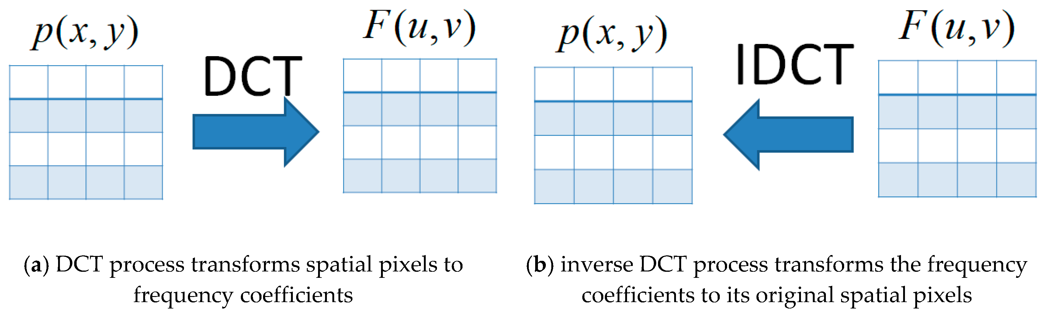
The discrete cosine transform (DCT) is a kind of transformation technique that separates the image into several spectral sub-bands of different importance [9]. The process of DCT is to transform an image from spatial pixels to frequency coefficients. The DCT is a reversible process. After the inverse DCT process, the frequency coefficients can be transformed to their original spatial pixels. A diagram of the DCT processes is shown in Figure 1.
The general DCT equation for a 2D image is defined by:
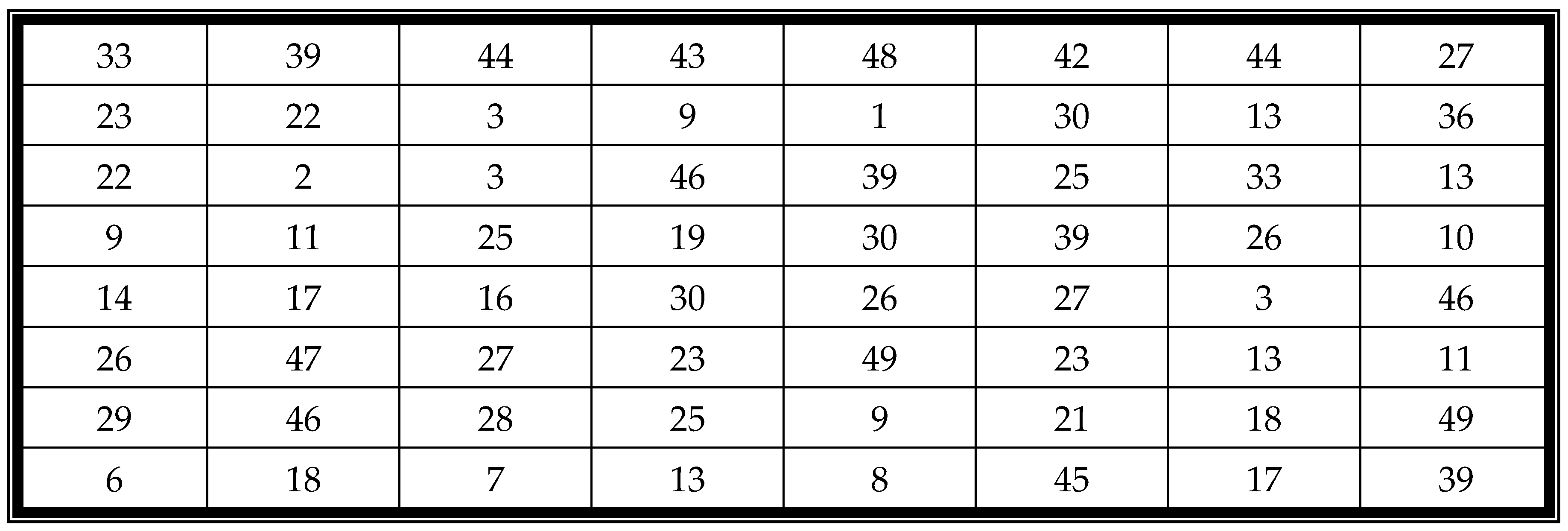
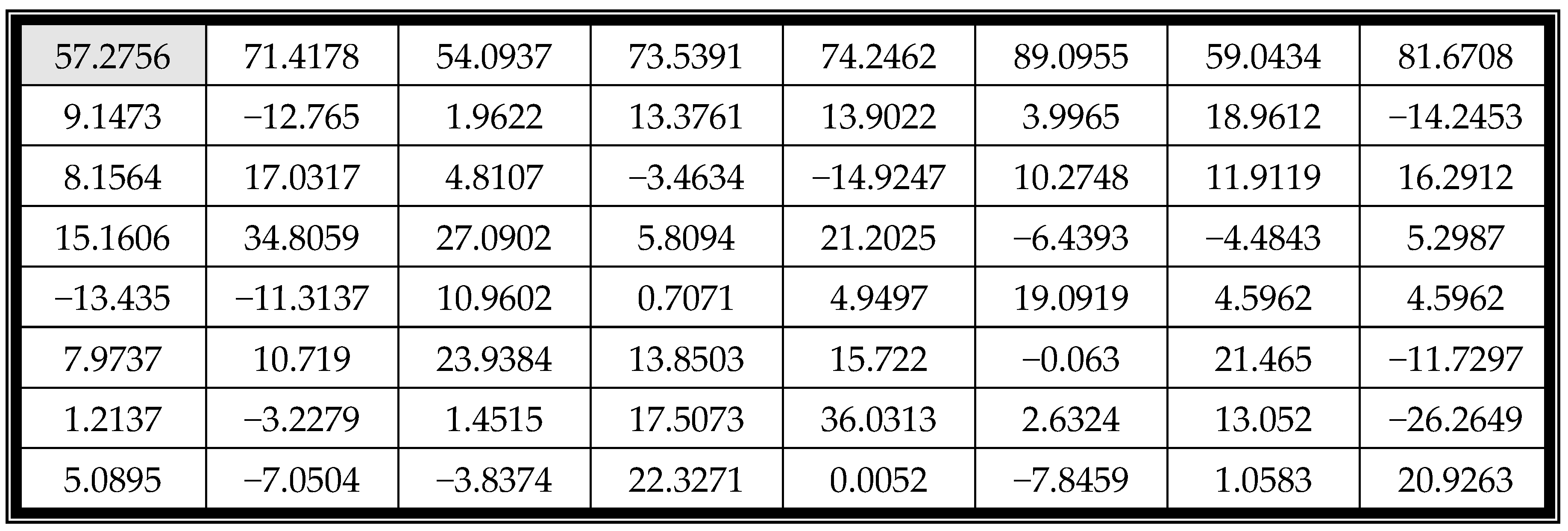
In the equation, is a pixel value in the coordinate of the block, and is the corresponding coefficient in the coordinate of the block. and are the width and height of the block, respectively. The top-left corner coefficient is the most important coefficient, called the DC coefficient or the constant components. The other coefficients are the alternating-current quantized coefficients called AC. For example, Figure 2 is a block with a size and Figure 3 is the coefficient table of Figure 2. The DC value of the figure is 57.2756, which defines the basic hue for the entire block.
The coefficient can be recovered to its original pixel by using the inverse DCT (IDCT) process. The IDCT equation is shown below:
2.2. Lu et al.’s Diagonal Watermarking Scheme
In 2012, Lu proposed a diagonal watermarking scheme to detect image manipulation [10]. In the scheme, an image is separated into four parts, and each part is divided into several blocks. Every block has a corresponding block in another part. Two blocks form a block pair. The average values of the two blocks are the authentication code. For example, Figure 4a,b are two example blocks. The average values of block and are
Then, the four most significant bits of Avg_A and Avg_B are extracted to form an authentication code. The extracted MSB are MSB_A = 0110 and MSB_B = 0010. The combined code is = 01100010. The combined code is then encrypted by a Keyed-hash message authentication code (HMAC) function to generate the authentication code HAC = 1010. The watermark of the blocks and is . The watermark is then embedded in the corresponding blocks in the three least significant bits of each pixel.
Lu’s scheme is simple and effective. However, the image quality of the scheme is not as good as that of other techniques. Hence, the proposed scheme improves the image quality and hiding capacity of Lu’s scheme.
3. Proposed Scheme mark
The diagram of the embedding process of the proposed scheme is shown in Figure 5. A cover image is divided into several blocks performed by DCT transformation. A watermark is constructed to be embedded in the block pair to generate the stego-image.
After receiving the stego-image, the extraction and recovery process is used to determine whether the image has been tampered with or not. This is shown in Figure 6.
The stego-image is divided into several blocks, and the watermark is extracted from the stego-pixels to determine if the block is valid or not. If the block is invalid, the extracted information is used to recover it.
The embedding and extraction process includes four major phases: authentication watermark generation, data embedding, tamper detection, and image recovery.
3.1. Authentication Watermark Generation Phase
The proposed scheme divides a cover image into several -sized blocks. Each block randomly chooses another block as a block pair. Let (BA, BB) be the block pair. Figure 7 shows the diagram of the image blocks of the proposed scheme. The proposed scheme generates an authentication watermark for the block pair (BA, BB) and embeds the code into the block pair.
The authentication watermark generation algorithm is shown below:
• Transform the blocks by DCT to obtain the coefficients DC and AC.
The transformation equation is:
For example, Figure 8a,b are two example blocks. The corresponding coefficients of the blocks are shown in Figure 8c,d.
• Quantize the coefficients using a quantization table with a quality factor (QF) [6].
For example, a quantization table with QF = 50 is shown in Figure 9. The coefficients in Figure 6c,d after quantization using Figure 7 are shown in Figure 8a,b.
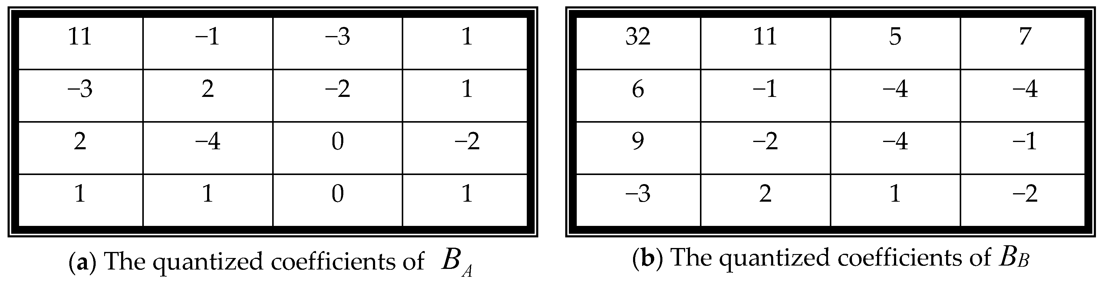
• Generate an authentication watermark using the DC values of BA and BB.
DC value is the most important value of the coefficients. The proposed scheme uses two DC values to generate the authentication watermark. The seven most significant bits of the two DC values of BA and BB are extracted to form MSB_DCA and MSB_DCB , respectively. Concatenate MSB_DCA and MSB_DCB to generate the first fourteen authentication watermark bits. Then, use XOR operator bitwise on the fourteen bits to generate a debugging bit . Perform NOT operator on the debugging bit to generate the final testing bit .
For example, in Figure 10a, the DC values of BA and BB are 11 and 32, respectively. The seven MSBs of 11 are (0000101)2, where (11)10 = (00001011)2. Hence, MSB_DCA = 0000101, and MSB_DCB = 0010000. The debugging bit is = 0 ⊕ 0 ⊕ 0 ⊕ 0 ⊕ 1 ⊕ 0 ⊕ 1 ⊕ 0 ⊕ 0 ⊕ 1 ⊕ 0 ⊕ 0 ⊕ 0 ⊕ 0 = 1, and the testing bit is = ~ = 0.
• Concatenate MSB_DCA, MSB_DCB, the debugging bit, and the testing bit to generate an authentication watermark (w), where w = MSB_DCA || MSB_DCB || || .
Following the same example, the authentication watermark is w = MSB_DCA || MSB_DCB |||| = 0000101||0010000||1||0 = 0000101001000010.
3.2. Authentication Watermark Embedding Phase
The authentication watermark is then concealed in each block of the block pair (BA, BB). The watermark is concealed twice in each block using Least Significant Bit Replacement (LSB). The proposed scheme separates each 4 4-sized block into two sub-blocks. Each 2 4-sized sub-block conceals one authentication watermark. Every pixel in the sub-block owns two secret bits.
For example, Figure 11a shows the binary string of each pixel of BA. The block BA is divided into two sub-blocks. The first sub-block is colored gray. The second sub-block is colored white. The watermark w = 0000101001000010 is then concealed in each binary string using LSB. Each pixel conceals two secret message bits to generate the stego-binary string. The watermark is concealed in both sub-blocks. Each sub-block owns one watermark. The results are shown in Figure 11c. Finally, the proposed scheme transforms the binary string into a decimal number to get the stego-pixels, such as in Figure 11e. The watermark is also concealed in BB to get the stego-block B’B, such as in Figure 11f.
3.3. Tamper Detection Phase
After receiving the stego-image, the receiver divides the stego-image into several -sized blocks. Then, the receiver follows the next four steps to extract the watermark and detect the tampering.
- Step 1:
- Watermark extraction and block detection
- Divide the block into two -sized sub-blocks.
- Extract two embedded bits from each stego-pixel to generate a watermark with sixteen bits for each sub-block. The watermark is w’ = MSB_DCA || MSB_DCB || || .
- Compare two extracted watermarks. If the watermark of the first sub-block is different from that of the second sub-block, then the block is suspicious.
- Step 2:
- Sub-block detection for suspicious blocks
- Use XOR operator bitwise on the fourteen bits of each watermark to generate a debugging bit .
- Compare with the 15th bit of the watermark . If does not equal to , then the block is invalid.
- Compare with the 16th bit of the watermark . If does not equal to , then the block is invalid.
- Step 3:
- Corresponding block detection
- Transform the block using DCT to obtain the coefficient DC values DCA and DCB from the block pair .
- Extract the seven most significant bits from DCA and DCB, called MSB_DC*A and MSB_DC*B.
- If MSB_DC*A MSB_DCA or MSB_DC*B MSB_DCB, then the block is valid. Otherwise, the block is invalid.
- Step 4:
- Closed neighboring detection for the valid block.
- If more than five close neighboring blocks are marked invalid, then the block is invalid.
3.4. Image Recovery Phase
The invalid blocks are recovered using two sequential steps:
- Step 1:
- Corresponding block recovery
- If both B’A and B’B are invalid, then the block cannot be recovered. The block is ignored, and the scheme continues to recover other blocks.
- Retrieve sixteen bits w’ from the valid block.
- If the block is valid, extract seven bits string from w’, which starts from the 1st bit to the 7th bit as MSB_DCA, and the bit string starts from the 8th bit to 14th bit as MSB_DCB.
- Randomly pad one 0 or 1 to the end of MSB_DCA and MSB_DCB to form new DC values.
- Replace the DC value of the invalid block with the new DC value and transform the coefficients into pixels using inverse DCT.
- Mark the block as valid.
- Step 2:
- Neighboring blocks recovery
- Recover the remaining invalid blocks using the neighboring blocks. The pixel values of the surrounding blocks are used to replace the pixel value of the invalid block.
4. Experimental Results
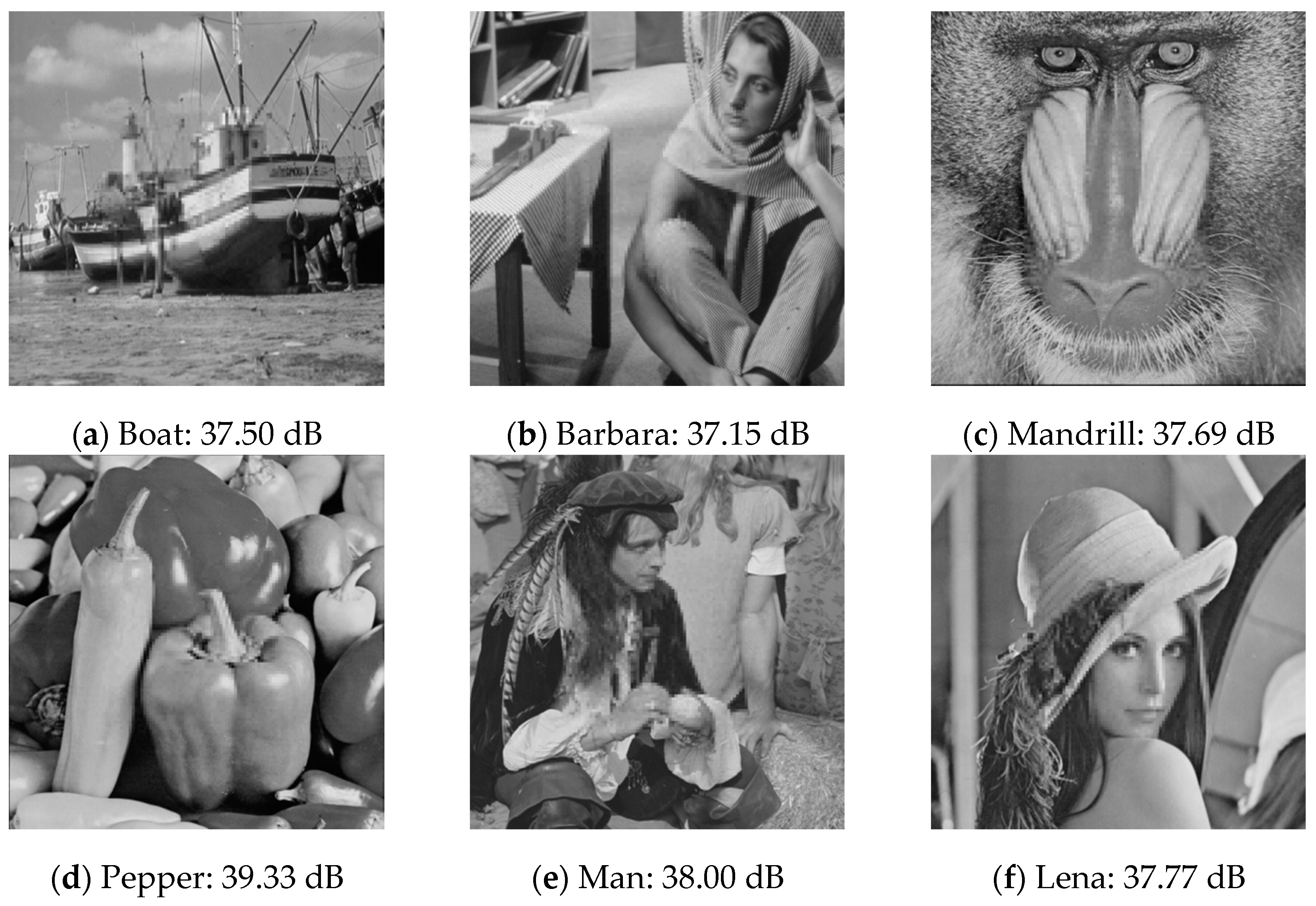
In this section, we shall demonstrate the effectiveness of the proposed scheme with several experimental results. Six 512 512-sized grayscale images were used to test the performance of the proposed scheme. The images were “Boat”, “Barbara”, “Mandrill”, “Pepper”, “Man”, and “Lena”, shown in Figure 12a–f, respectively. The scheme was implemented by MATLAB R2014b in Windows 10 64-bit operating system, Intel® Core(TM) i7-6700 CPU @ 3.40 GHz 3.40 GHz, 16GB RAM.
In order to measure the visual quality of the stego-image, the similarity between the cover image and the stego-image was calculated using the peak signal-to-noise ratio (PSNR) given by:
where dB refers to the decibels, and MSE represents the mean squared error between the cover image and the stego-image, and is given by:
The watermarked images are shown in Figure 13a–f, respectively, for each test image. The PSNR values of the test images are higher than 46 dB. The image quality of the stego-image is excellent.
In the first experiment, we cropped the central area of each watermarked image to generate the tampered image. The tampered images are shown in Figure 14a–f. The most important features of each watermarked image were cropped. Figure 15 displays the recovered images of Figure 14. The image quality of the recovered image is good since the PSNR value of each image is higher than 37.5 dB.
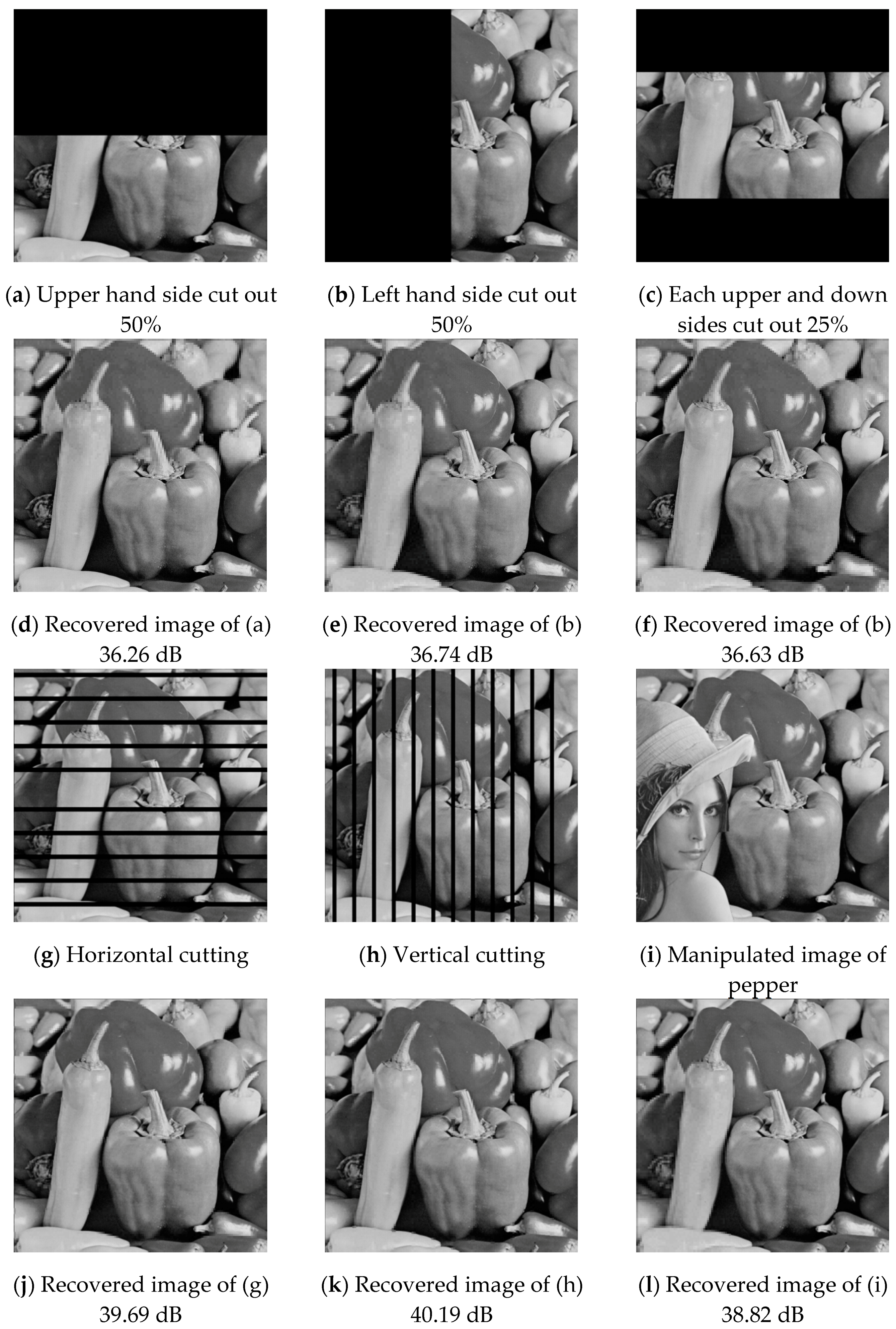
With the second experiment, we blacked out 50% of each test image at various locations. Six different types of tampering distributions are shown in Figure 16a–c,g–i. The recovered images are shown in Figure 16d–f,j–l, respectively. The image quality is higher than 36.2 dB.
In the third experiment, two kinds of malicious manipulations were applied to the test images Boat and Mandrill. The manipulated images are shown in Figure 17a,c and their recovered images are shown in Figure 17b,d, respectively. The PSNR values of the recovered images are higher than 35 dB.
Table 1 shows the execution time of each phase by using the proposed scheme. The average time of embedding processing is 4.77 s which contains 1.31 s for DCT, 2.47 s for XOR, 1 s for embedding operator. The average times of extraction processing and recovering processing are 1.25 and 1.4 s, respectively. The execution time of the proposed scheme is very short. Hence, the proposed scheme is very suitable for mobile device.
The next experiment compared the performance of the proposed scheme and Lu’s scheme. Table 2 shows the image qualities of the stego-image and the recovered image using the proposed scheme and Lu’s scheme. In Table 2, the stego-image quality of the proposed scheme is 46.3 dB, which is higher than Lu’s scheme of 38.43 dB. Other images have similar situations. For the stego-image, the image quality of the proposed scheme is, on average, higher than Lu’s scheme of 7.8 dB. For the recovered image, the image quality of the proposed scheme is, on average, higher than Lu’s scheme of 6 dB.
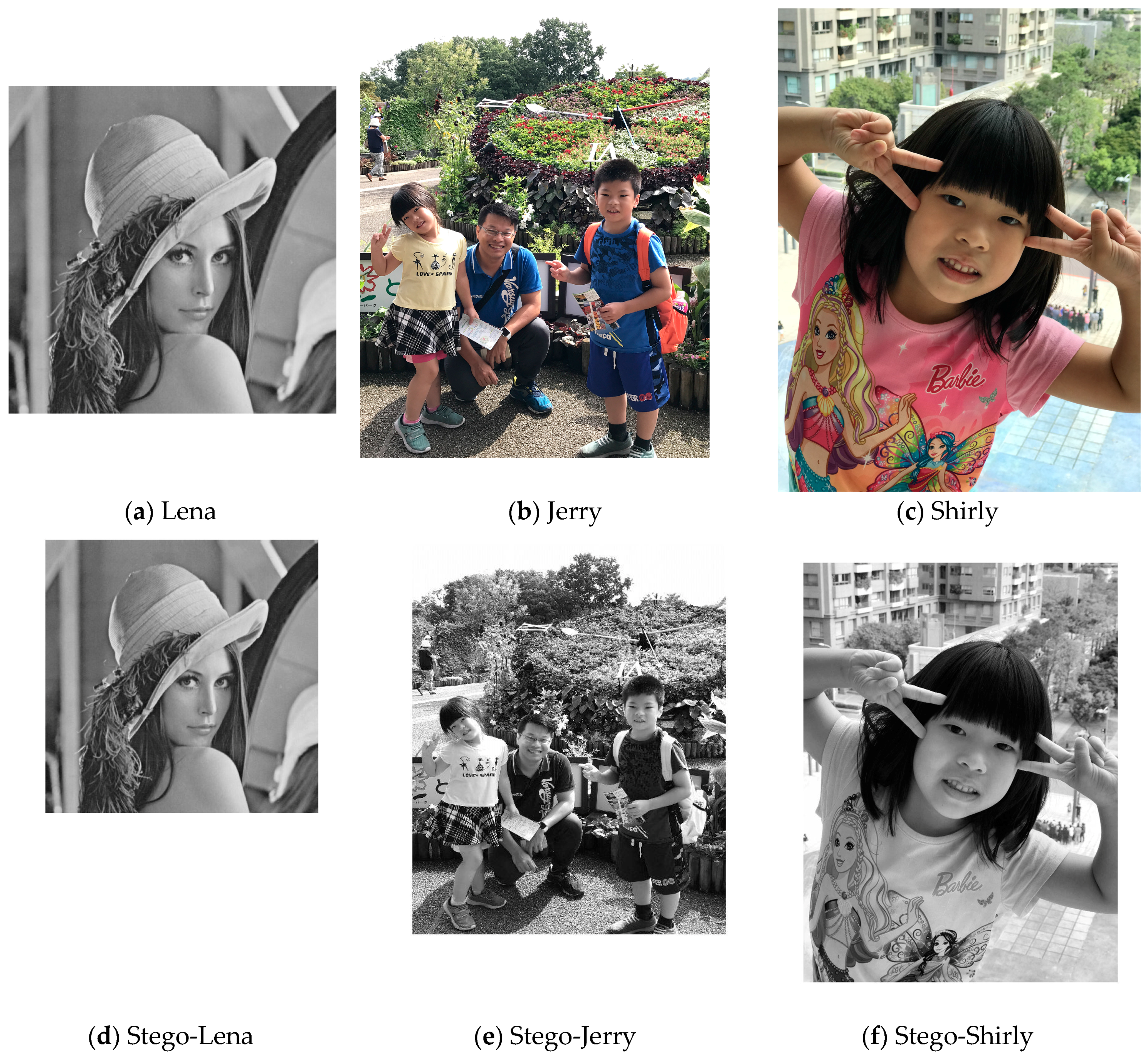
The proposed scheme was not only developed in a personal computer (PC) environment but also implemented in the mobile device iPad Pro 256GB with iOS11 system. The system was developed by Mathworks. Three test images with large sizes were used to test the performance of the proposed scheme: Lena (1252 1252), Jerry (2016 1512), and Shirly (4032 3024). Figure 18 shows the test images with large sizes. The experimental results of these test images are shown in Table 3. For the test image Lena, sized 12521252, the execution time of the PC is about 10 s and that of the iPad is about 11 s. For the test image Jerry, sized 2016 1512, the execution time of the PC is 19 s and that of the iPad is 27 s. For the largest test image, Shirly, sized 4032 3024, the execution time of the PC is 78 s and that of the iPad is 91 s. The PSNR values are the same in different devices. From the results, we can see that the proposed scheme can perform very well on the mobile device.
5. Conclusions
This paper proposes an effective authentication scheme for image tampering detection and recovery. The proposed scheme applies very simple hiding operators to conceal authentication information in the cover image. The image quality of the stego-image is higher than 46 dB. Furthermore, the tampered image can be recovered effectively. The image quality of the recovered image is higher than 37.5 dB. According to the experimental results, the stego-image quality of the proposed scheme is more than that of Lu’s scheme of 7.8 dB. The recovered image quality of the proposed scheme is higher than that of Lu’s scheme of 6 dB. Furthermore, the proposed scheme can handle large image sizes in a short execution time. The execution time in a mobile device is only a few seconds longer than that in a PC device. The execution time of the proposed scheme is short, which is suitable for application in a mobile environment. The increasing time is also acceptable. Moreover, Lu concealed the watermark in the spatial domain that is non-robust. The watermark is easily removed. The proposed scheme embeds the watermark in the frequency domain, which can ensure the robustness.
Acknowledgments
The authors would like to thank the Ministry of Science and Technology of the Republic of China, Taiwan, for financially supporting this paper under Contract No. Most 105-2221-E-324-020.
Author Contributions
Chin-Chen Chang designed the algorithm, Tzu-Chuen Lu conducted the experiments, analyzed the results, and wrote the manuscript, Zhao-Hua Zhu conducted the experiments, Hui-Shih Leng conducted the literature review.
Conflicts of Interest
The authors declare no conflict of interest.
References
- Tirkel, A.Z.; Rankin, G.A.; Van Schyndel, R.M.; Ho, W.J.; Mee, N.R.A.; Osborne, C.F. Electronic Water Mark. Available online: http://goanna.cs.rmit.edu.au/~ronvs/papers/DICTA93.PDF (accessed on 28 December 2017).
- Mielikainen, J. LSB matching revisited. IEEE Signal Process. Lett. 2006, 13, 285–287. [Google Scholar] [CrossRef]
- Lyu, W.L.; Chang, C.C.; Wang, F. Image authentication and self-recovery scheme based on the rehashing model. J. Inf. Hiding Multimed. Signal Process. 2016, 7, 460–474. [Google Scholar]
- Yu, M.; Wang, J.; Jiang, G.; Peng, Z.; Shao, F.; Luo, T. New fragile watermarking method for stereo image authentication with localization and recovery. AEU-J. Electron. Commun. 2015, 69, 361–370. [Google Scholar] [CrossRef]
- Qi, X.; Xin, X. A singular-value-based semi-fragile watermarking scheme for image content authentication with tamper localization. J. Visual Commun. Image Represent. 2015, 30, 312–327. [Google Scholar] [CrossRef]
- Al-Otum, H.M. Semi-fragile watermarking for grayscale image authentication and tamper detection based on an adjusted expanded-bit multiscale quantization-based technique. J. Vis. Commun. Image Represent. 2014, 25, 1064–1081. [Google Scholar] [CrossRef]
- Huang, F.J.; Qu, X.C.; Kim, H.J. Reversible data hiding in JPEG images. IEEE Trans. Circuits Syst. Video Technol. 2016, 26, 1610–1621. [Google Scholar] [CrossRef]
- Khayam, S.A. The Discrete Cosine Transform (DCT): Theory and Application. 2003. Available online: http://citeseerx.ist.psu.edu/viewdoc/summary?doi=10.1.1.184.6102 (accessed on 20 December 2017).
- Kornblum, J.D. Using JPEG quantization tables to identify imagery processed by software. Digital Investig. 2008, 5, 21–25. [Google Scholar] [CrossRef]
- Lu, T.C. Diagonal watermark scheme for image manipulation detection and recovering. Commun. CCISA 2012, 18, 41–58. [Google Scholar]
Figure 1.
The processes of discrete cosine transform (DCT) and inverse DCT (ICDCT).

Figure 2.
An example image block.

Figure 3.
The DCT coefficients of Figure 2.
Figure 3.
The DCT coefficients of Figure 2.

Figure 4.
The example blocks.
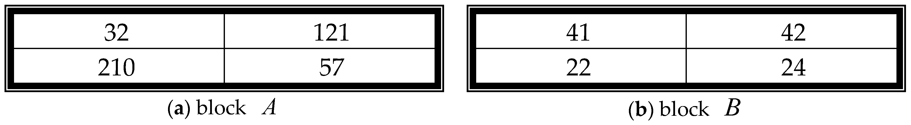
Figure 5.
The image embedding process of the proposed scheme.
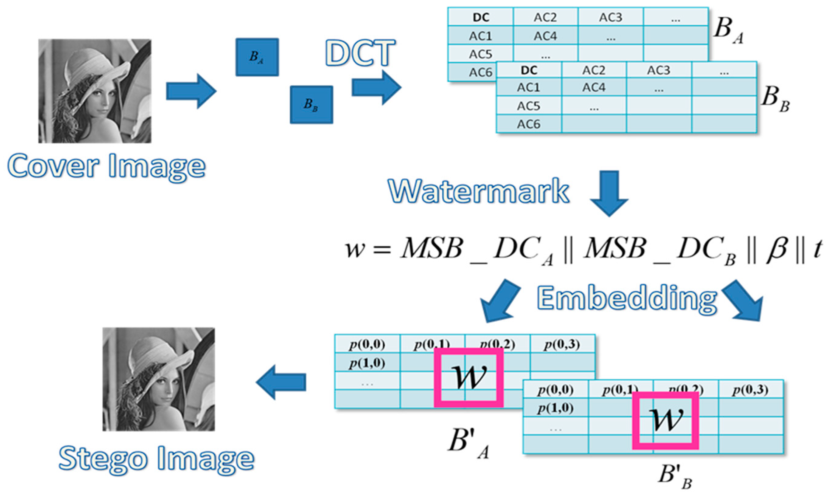
Figure 6.
The extraction and recovery process of the proposed scheme.
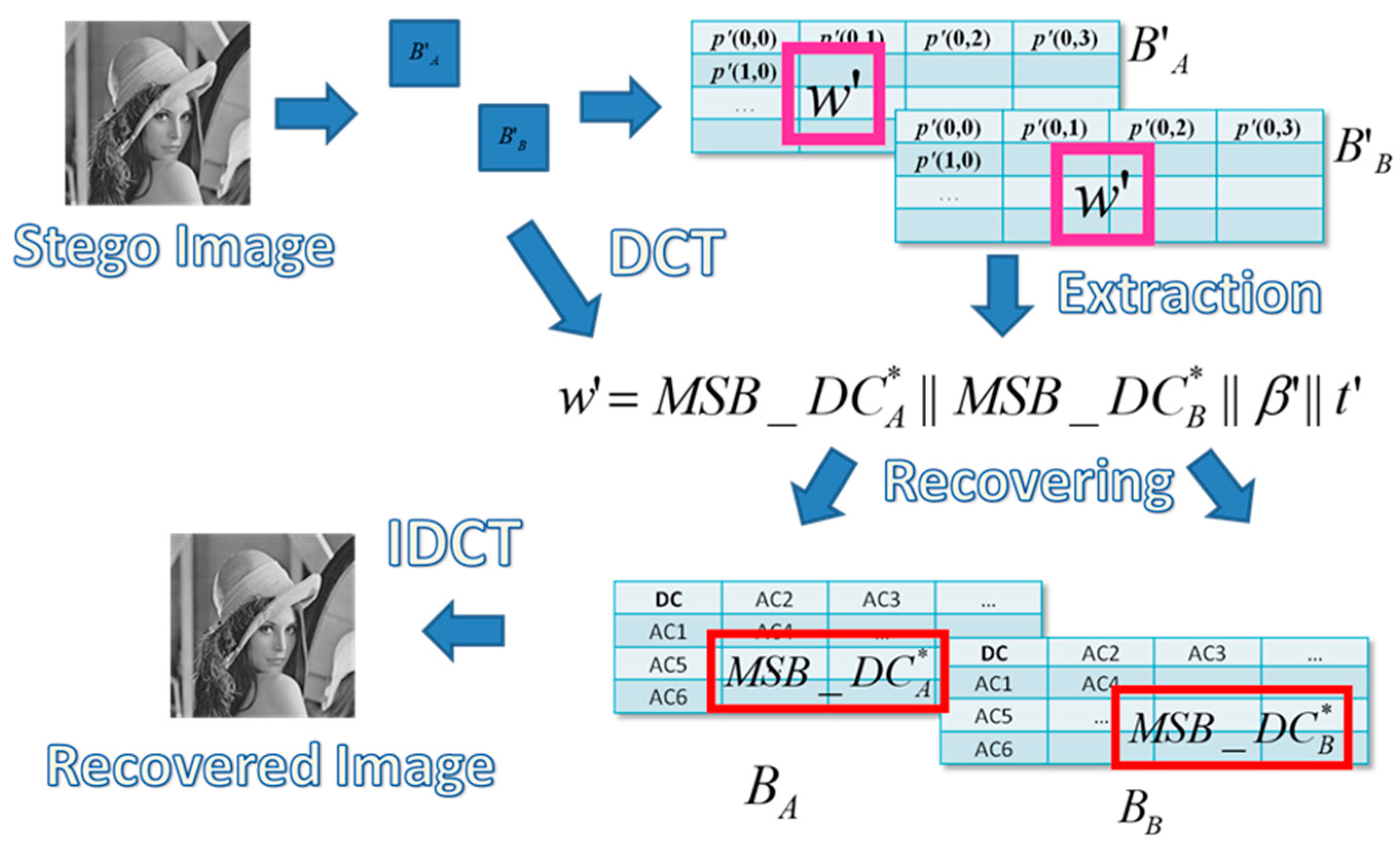
Figure 7.
The image blocks of the proposed scheme.

Figure 8.
An example block pair (, ) and its corresponding coefficients.
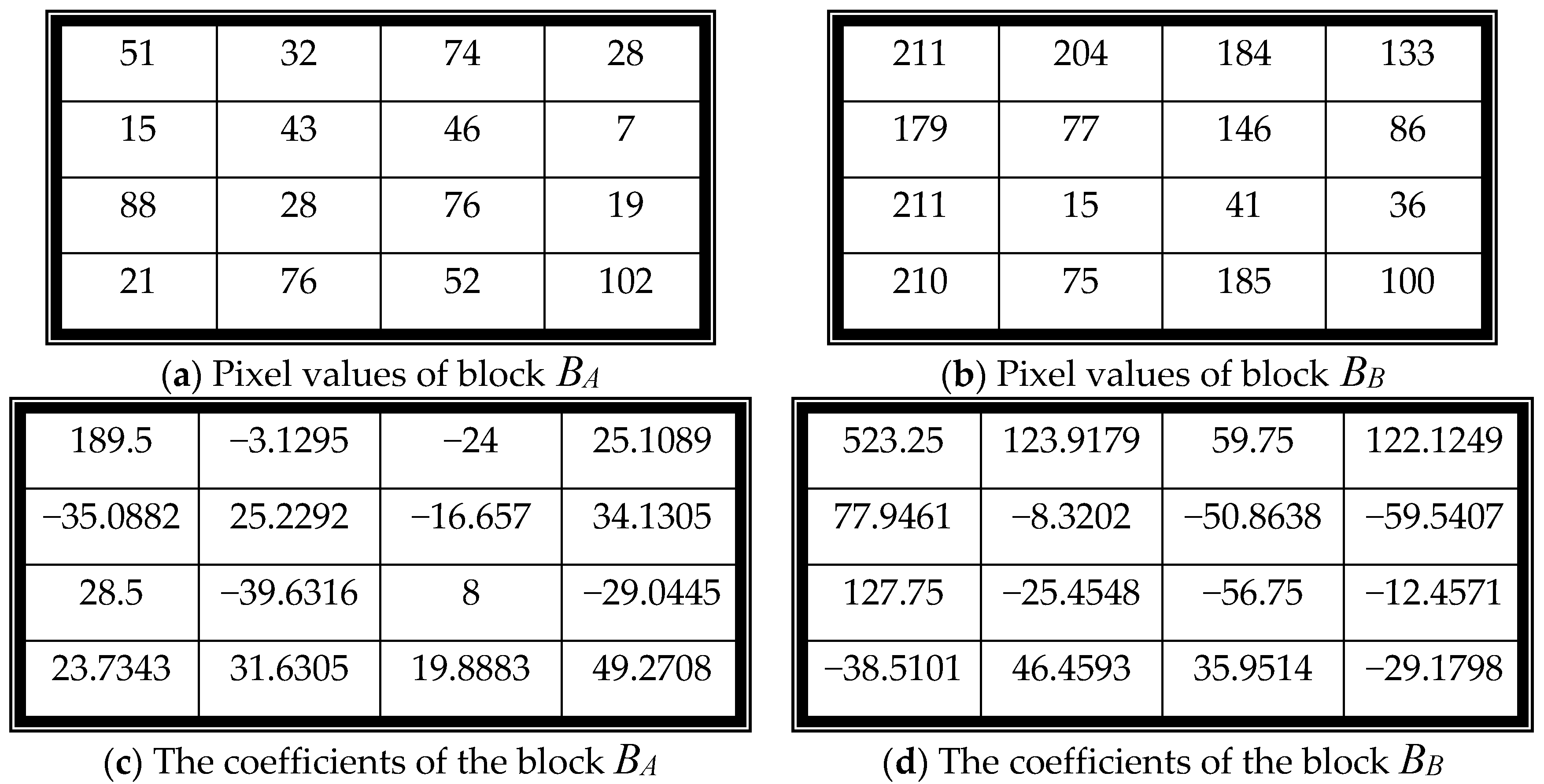
Figure 9.
The quantization table with quality factor (QF) = 50.

Figure 10.
The quantized coefficients of block pair (BA, BB).

Figure 11.
The embedding example of the proposed scheme with w = 0000101001000010.
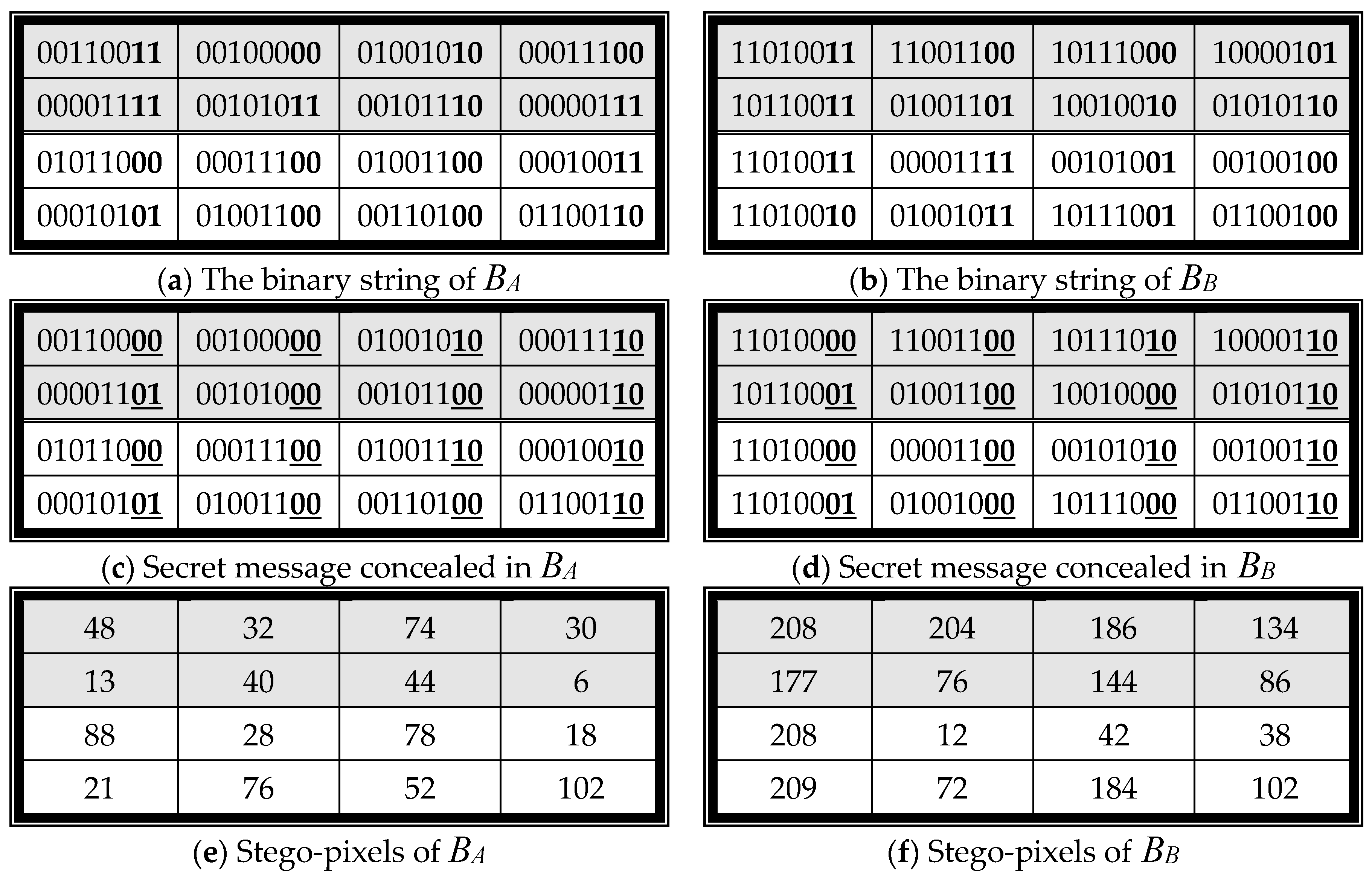
Figure 12.
The test images.
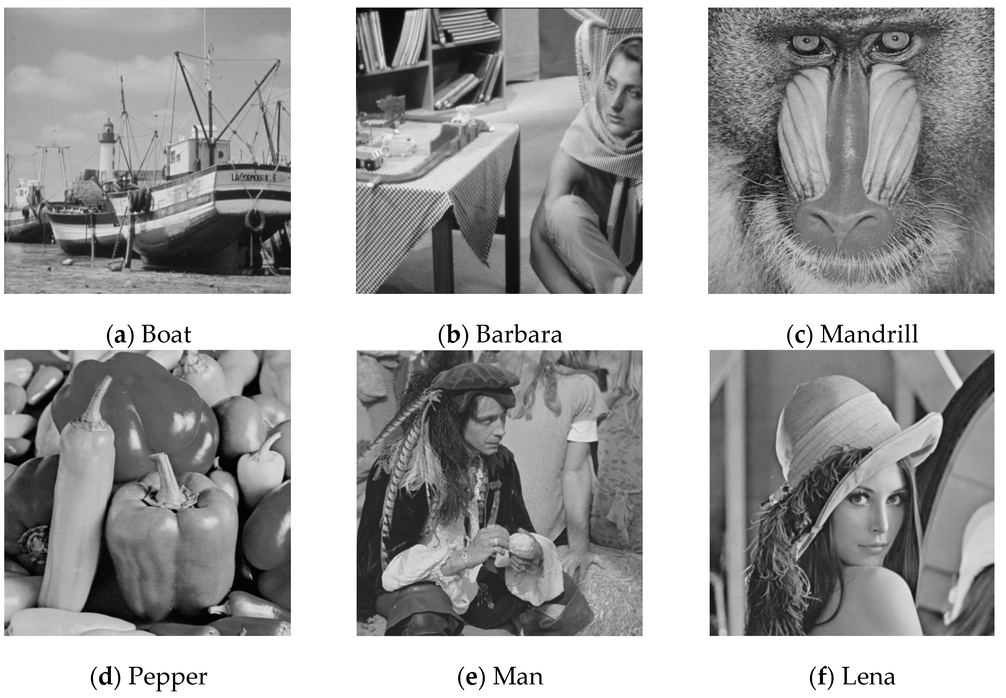
Figure 13.
The stego-image of each test image.

Figure 14.
The tampered image of each test image.
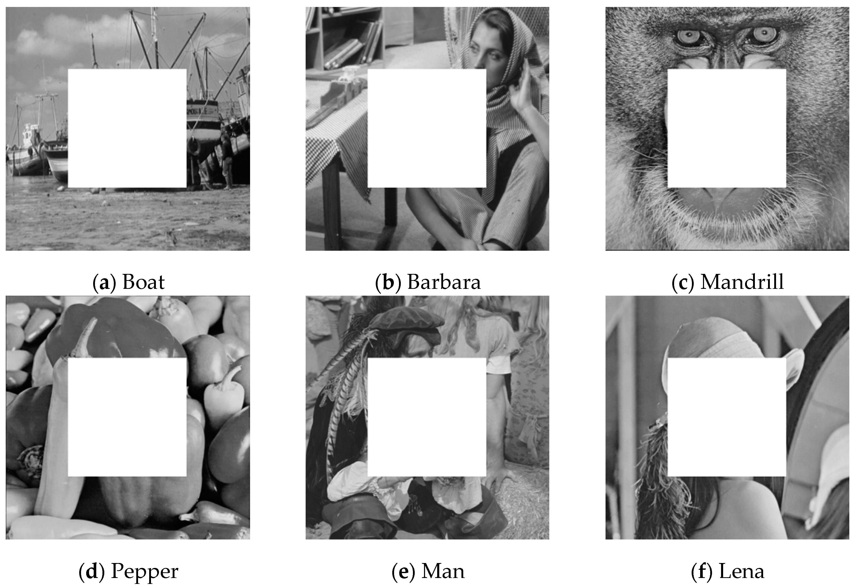
Figure 15.
The recovered image of each test image.

Figure 16.
Six different types of tampering distribution.

Figure 17.
Two kinds of malicious manipulations.
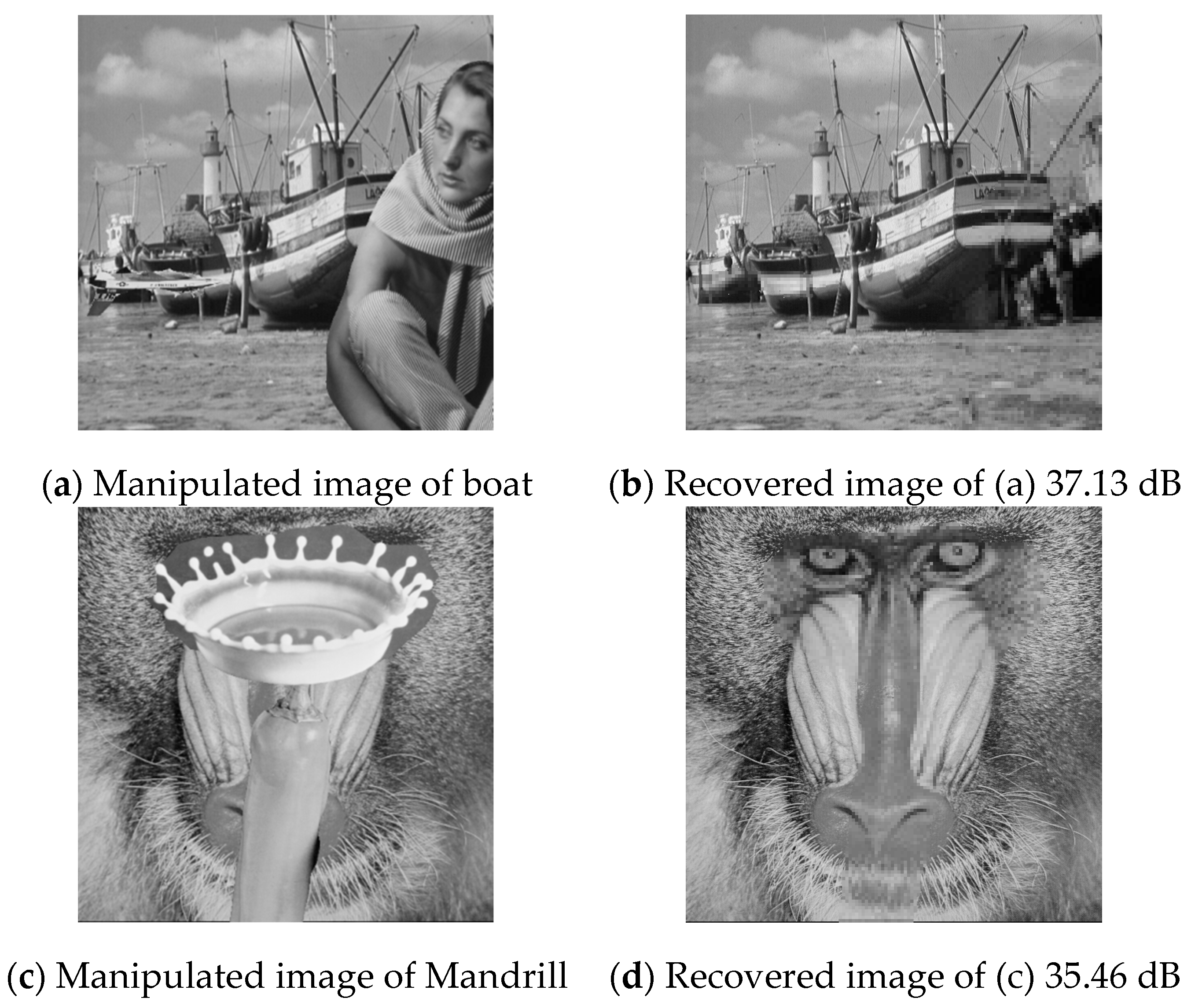
Figure 18.
The cover images and the stego-images of large size images.

Table 1.
The execution time of each phase (unit: second).
| Time(s) | Embedding Processing | Extraction Processing | Recovering Processing | |||
|---|---|---|---|---|---|---|
| DCT | XOR | Embedding | Total | |||
| Boat | 1.30 | 2.49 | 1.01 | 4.80 | 1.24 | 1.40 |
| Barbara | 1.30 | 2.45 | 0.99 | 4.74 | 1.24 | 1.40 |
| Mandrill | 1.31 | 2.46 | 0.99 | 4.76 | 1.25 | 1.41 |
| Pepper | 1.30 | 2.46 | 0.99 | 4.76 | 1.25 | 1.41 |
| Man | 1.30 | 2.46 | 0.99 | 4.75 | 1.24 | 1.40 |
| Lena | 1.31 | 2.48 | 1.01 | 4.80 | 1.25 | 1.40 |
| Average | 1.31 | 2.47 | 1.00 | 4.77 | 1.25 | 1.40 |
Table 2.
Comparisons between the proposed scheme and Lu’s scheme.
| Image | Method | Boat | Barbara | Mandrill | Pepper | Lena |
|---|---|---|---|---|---|---|
| Stego-Image | Proposed | 46.30 dB | 45.95 dB | 46.36 dB | 46.24 dB | 46.18 dB |
| Lu’s | 38.43 dB | 38.23 dB | 38.20 dB | 38.31 dB | 38.26 dB | |
| Recovered Image | Proposed | 37.50 dB | 37.15 dB | 37.69 dB | 39.33 dB | 37.77 dB |
| Lu’s | 31.50 dB | 31.98 dB | 32.70 dB | 33.52 dB | 33.10 dB |
Table 3.
The experimental results of the large size images.
| Device | File Name | Size | Time (s) | PSNR |
|---|---|---|---|---|
| PC | Lena | 1252 1252 | 10.4393 | 46.16 |
| Jerry | 2016 1512 | 19.7033 | 45.32 | |
| Shirly | 4032 3024 | 78.2458 | 46.08 | |
| iPad | Lena | 1252 1252 | 11.5551 | 46.16 |
| Jerry | 2016 1512 | 27.7589 | 45.32 | |
| Shirly | 4032 3024 | 91.1173 | 46.08 |
© 2018 by the authors. Licensee MDPI, Basel, Switzerland. This article is an open access article distributed under the terms and conditions of the Creative Commons Attribution (CC BY) license (http://creativecommons.org/licenses/by/4.0/).
Share and Cite
MDPI and ACS Style
Chang, C.-C.; Lu, T.-C.; Zhu, Z.-H.; Tian, H. An Effective Authentication Scheme Using DCT for Mobile Devices. Symmetry 2018, 10, 13. https://doi.org/10.3390/sym10010013
AMA Style
Chang C-C, Lu T-C, Zhu Z-H, Tian H. An Effective Authentication Scheme Using DCT for Mobile Devices. Symmetry. 2018; 10(1):13. https://doi.org/10.3390/sym10010013
Chicago/Turabian StyleChang, Chin-Chen, Tzu-Chuen Lu, Zhao-Hua Zhu, and Hui Tian. 2018. "An Effective Authentication Scheme Using DCT for Mobile Devices" Symmetry 10, no. 1: 13. https://doi.org/10.3390/sym10010013
Note that from the first issue of 2016, this journal uses article numbers instead of page numbers. See further details here.