WPCB-Tree: A Novel Flash-Aware B-Tree Index Using a Write Pattern Converter


1
Department of Computer Science, Korea - Vietnam Friendship Information Technology College, Da Nang 550000, Vietnam
2
School of Computer Science and Engineering, Soongsil University, Seoul 06978, Korea
*
Author to whom correspondence should be addressed.
Symmetry 2018, 10(1), 18; https://doi.org/10.3390/sym10010018
Submission received: 23 October 2017
/
Revised: 30 December 2017
/
Accepted: 3 January 2018
/
Published: 8 January 2018
Abstract
:For the past few years, flash memory has been widely used because of its prominent advantages such as fast access speed, nonvolatility, high reliability, and low power consumption. However, flash memory still has several drawbacks that need to be overcome, e.g., the erase-before-write characteristic and a limited life cycle. Among these drawbacks, the erase-before-write characteristic causes the B-tree implementation on flash memory to be inefficient because it generates many erase operations. This study introduces a novel B-tree index structure using a write pattern converter (WPCB-tree) for flash memory. A WPCB-tree can minimize the risk of data loss and can improve the performance of the B-tree on flash memory. This WPCB-tree uses some blocks of flash memory as a buffer that temporarily stores all updated nodes. When the buffer is full, a buffer block is selected by a greedy algorithm, then the node pages in the block are converted into a sequential write pattern, and finally they are written into flash memory. In addition, in the case that all key values of a leaf node are continuously inserted, the WPCB-tree does not split the leaf node. As a result, this mechanism helps the WPCB-tree reduce the number of write operations on the flash memory. The experimental results show that the proposed B-tree variant on flash memory yields a better performance than that of other existing variants of the B-tree.
1. Introduction
Flash memory is applied in various fields from integrated embedded systems, mobile devices, and personal computers to large-scale server systems because it has many positive consequences such as high-speed access, low power consumption, small size, and high reliability. Although these advantages have lead flash memory to become a commonly used memory technology, its downsides, including erase-before-write, limited life cycle, and higher cost than a normal HDD, should not be overlooked [1,2,3,4,5]. Among these mentioned weak points, erase-before-write is a critical characteristic that needs to be mitigated because an erase operation leads to many read and write operations and shortens the life cycle of flash memory.
To help hosts access the data stored in flash memory devices such as by accessing disk drives, a module called the Flash Translation Layer (FTL) is used to process the logical-to-physical address mapping between the host and flash memory, and provides the general block device interface. Moreover, FTL hides the erase-before-write characteristic of flash memory and exposes only an array of logical addresses to the host. The FTL is vital and has two main features: address mapping and garbage collection. To date, some FTL algorithms have been proposed to confine physical limitation characteristics and improve the overall performance of flash memory.
Despite the fact that performance of flash memory has been enhanced by using FTL algorithms, it may encounter performance degradation problems when implementing the B-tree index directly, as the overwrite operations on flash memory frequently occur in the case of updating nodes. In order to address this issue, a number of B-tree variants have been proposed. However, these B-trees suffer from the risk of data loss or the performance degradation problem.
This paper proposes a novel B-tree index structure using a mechanism of write pattern conversion which uses some flash blocks as a buffer to temporarily store updated nodes. When the buffer runs out of available space for a newly updated node, a buffer block is selected by the greedy algorithm, then random order pages located in the block are converted to sequential order pages by a converter, and finally they are sequentially written into the flash memory. A write pattern converter B-tree (WPCB-tree) could minimize the risk of data loss and reduce a lot of the performance cost because many random writes are converted to sequential writes.
The experimental results indicate that the proposed B-tree index structure achieves a better performance in comparison with the other existing B-trees.
The rest of the paper is organized as follows. Section 2 reviews basic knowledge of flash memory and flash-aware index structures, and discusses the drawbacks of related work. We present the design of the WPCB-tree and its operations in Section 3 and Section 4, respectively. Section 5 presents the system analysis. Section 6 experimentally evaluates the efficiency of the WPCB-tree and, finally, Section 7 concludes the paper.
2. Background and Related Works
2.1. Flash Memory
Flash memory [3] is a type of nonvolatile storage device that is widely used nowadays. Unlike a hard disk, flash memory consists of a number of NAND flash memory arrays, a controller, and an SRAM (Static Random Access Memory)—which is used as an I/O buffer and stores mapping information. The flash memory is organized in many blocks and each block contains a fixed number of pages (pp. 32, 64, 128, etc.). A page is the smallest unit of read and write operations while erase operations are handled by the block.
Flash memory supports three basic operations: read, write, and erase. The read operation is the fastest one among these operations, and is about 10 times faster than a write operation. The erase operation is very time-consuming—the erase time per block is usually about 2 ms, which is over 10 times higher than the time taken for a write operation.
The flash memory is characterized by high-density data storage. It requires an intermediate software layer called the Flash Translation Layer (FTL) for management and control of data, by which the overall performance of the flash memory can be enhanced. The main goal of FTL is to emulate the functionality of a normal block device with flash memory which hides the presence of the erase-before-write characteristic. Two important functions of FTL are address translation and garbage collection.
The address mapping is classified into the sector mapping scheme, block mapping scheme, and hybrid scheme [1,6,7,8,9,10,11]. The sector mapping scheme maps every logical sector from the host to the corresponding physical page of flash memory. Upon receiving a write request from the host, FTL finds a free page and writes the data into the page. It is highly flexible as a logical page can be written to any physical page in the flash memory.
However, the size of the mapping table significantly increases as the storage capacity increases because every logical sector has its own physical sector address. For example, with a 1 GB flash memory having 8192 blocks and 32 pages per each block, the mapping table has 262,144 entries (32 × 8192).
On the other hand, the mapping unit of a block mapping scheme is a block. The physical location of a logical page is fixed to a certain page offset within a block. When receiving a write request, the FTL first obtains the physical block based on the block mapping table, and then calculates the sector offset of the physical block. If the page is free, the FTL writes the data into the page; otherwise, the whole block must be erased before writing the data into it. Block mapping suffers from frequent overwrite operations that invoke many erase and write operations on the flash memory. The size of the block mapping table is much smaller than the size of the sector mapping table. For a 1 GB flash memory that has, for instance, 8192 blocks and 32 pages per each block, the mapping table has 8192 entries.
In real storage systems, many block mapping algorithms are employed in combination with the sector mapping. A family of hybrid mapping schemes is introduced to address the shortcomings of the sector mapping scheme and the block mapping scheme. In the hybrid mapping schemes, physical blocks are logically partitioned into two groups: data blocks and log blocks. When a write request arrives, the hybrid FTL first writes new data in a log block and invalidates data in the corresponding target data block. When the log block is full, the log block is merged with the corresponding data block. The block mapping scheme is applied to the data blocks and sector mapping is applied to the log blocks. They are kept in a small RAM for performance improvement purposes.
2.2. B-Tree on Flash Memory
A B-tree index [12] is a data structure that is widely used in many file systems and database management systems due to its quick access capability. However, the frequent random writes of the B-tree may degrade the efficiency of the B-tree index on flash memory as well as the lifecycle of the flash memory due to the erase-before-write limitation of flash memory.
Figure 1 is an example of a B-tree index on flash memory which employs the block mapping scheme. Assume that each node of the tree is stored in one page of the flash memory. If a record with key value 12 is inserted, an in-place-update occurs in node C. Valid nodes (A and B) are first copied to an empty block; afterward, it is the turn of leaf node C’ where the new record with key value 12 is inserted, followed by an erase operation for the block containing leaf node C.
To address these problems, many variants of B-tree have been proposed for flash memory [13]. The B-tree variants can be classified into three groups: buffer-based group, structure-modified group, and hybrid group. The buffer-based B-tree variants use a part of the main memory resource as a buffer to delay update operations on the B-tree. Every inserted record is temporarily stored in the buffer. When the buffer is full, all records in the buffer are flushed to flash memory. These B-tree variants yield good performance because the number of flash operations is reduced. However, they carry a risk of data loss if a power failure occurs since many records are in the main memory. Moreover, they consume some main memory resources which are limited in various embedded systems. Therefore, these B-tree variants are not suitable for small embedded systems. The other B-tree variants which, in contrast, change the structure of the B-tree to avoid in-place-updates are called the structure-modified B-trees. All inserted records are temporarily stored in a log area. When the log area is full, it is merged with the data area of the flash memory. These B-tree variants write inserted records directly into flash memory; hence, they are more reliable and use less main memory resources than the others. However, their performance is poor because they invoke many additional flash operations. Lastly, the hybrid group is a combination of the buffer-based group and the structure-modified group. It inherits strong points and reduces some limitations of the two above groups.
In summary, either of above-mentioned B-tree groups have a risk of data loss because they use some RAM resources as a writing buffer, or suffer from performance degradation since they invoke additional flash operations. These limitations motivate us to propose a new scheme that can reduce the risk of data loss, the main memory resource used, and the number of additional flash operations.
2.3. The Limitation of Random Write Performance
In terms of sequential/random read and sequential write performance, flash memory has a poor random write performance [14,15]. Moreover, it is observed that flash memory slows down over time, and even significantly degrades its performance under random-write-dominated workloads. The random write performance of flash memory is particularly bad because it generates a complicated address mapping table. On the other hand, random writes may result in full merge operations, which are the most costly operations and include a number of read and write operations along with two erase operations. Table 1 shows that the cost of random write is much higher than the cost of sequential write—about 12 times, where the cost here is defined as the number of flash operations generated by performing write operations.
Figure 2 shows the experimental results of random write pattern performance and sequential write pattern performance respectively via FTL when 1,000,000 insert commands are performed. Figure 2 shows the number of write operations (Figure 2a) and the number of erase operations (Figure 2b). As shown in the figures, the cost of the sequential write pattern is about four times smaller than that of the random write pattern. In the same workload and the same flash memory configuration, the number of write operations by the sequential write pattern is much lower than that by the random write pattern. It is totally similar in the erase case.
Moreover, when insert, update, or delete operations are performed on a B-tree, a large number of random writes are generated. The major bottleneck of the B-tree index for flash memory is the number of random writes due to the erase-before-write characteristic. Therefore, converting a random write pattern into a sequential write pattern improves the performance of the B-tree on flash memory.
3. WPCB-Tree: A B-Tree Using a Write Pattern Converter
This section presents a new B-tree index structure using a write pattern converter named a WPCB-tree. The main goals of this WPCB-tree are as follows: (1) to quickly create the index structure with very little use of the main memory resource; (2) to alleviate the disadvantage of the random write pattern by converting the write pattern from random to sequential; and (3) to ensure that the data is nonvolatile in the case of sudden power failure. The WPCB-tree avoids the erase-before-write characteristic and reduces the number of write operations by using a novel method and mechanism. The method is summarized as follows. Every updated node is temporarily stored in a flash-resident buffer called the “Transit Buffer Manager (TBM)”. When the TBM is full, one block is selected (victim block) by the greedy algorithm, and this block is then converted from a random write pattern into a sequential write pattern by a module called the “Write Pattern Converter (WPC)”. After conversion, the victim block is merged with the corresponding data block. Furthermore, the WPCB-tree also employs an overflow mechanism which does not split the leaf nodes if all key values of those leaf nodes are inserted in a contiguous order and does not merge nodes if a node is underflowing. This helps the WPCB-tree to reduce the number of write operations. A detailed explanation will be provided in the next subsections.
3.1. Design of the WPCB-Tree
In order to achieve the aforementioned goals, we maintain three modules named the original B-tree module, the Transit Buffer Manager (TBM), and the Write Pattern Converter (WPC). All these components are located in the flash memory to avoid data loss. Additionally, to improve search performance and to minimize the overhead of searching the victim blocks, we maintain a main memory-resident table named the Summary table which manages the information on blocks of the TBM. Figure 3 describes the general model of the WPCB-tree. In this model, the B-tree module is the same as the conventional B-tree. The TBM aims to reduce the number of write and erase operations on the flash memory. It is used to temporarily store pages of the corresponding updated nodes of the B-tree. The goal of the WPC is to convert node pages in the TBM from a random write pattern to a sequential write pattern before writing them into flash memory through the FTL. The Summary table is used to manage the information on blocks of TBM. The information in the Summary table includes the block number and logical page number of pages which store updated nodes in the TBM.
3.2. Transit Buffer Manager
The TBM is used to temporarily store all updated nodes of the B-tree. It uses some blocks of flash memory as a buffer. The blocks in TBM are called buffer blocks. The size of the TBM (e.g., the number of the blocks in the TBM) is variable depending on the number of records which are inserted and the number of available blocks. However, the size of the TBM may grow unexpectedly when the number of records is large. If the size of the TBM grows in an uncontrolled manner, it will consume a lot of flash memory resources. Therefore, to overcome this problem, we use a system parameter C to control the maximum size of the TBM. If the size of the TBM grows beyond C, the size of the TBM is fixed at C.
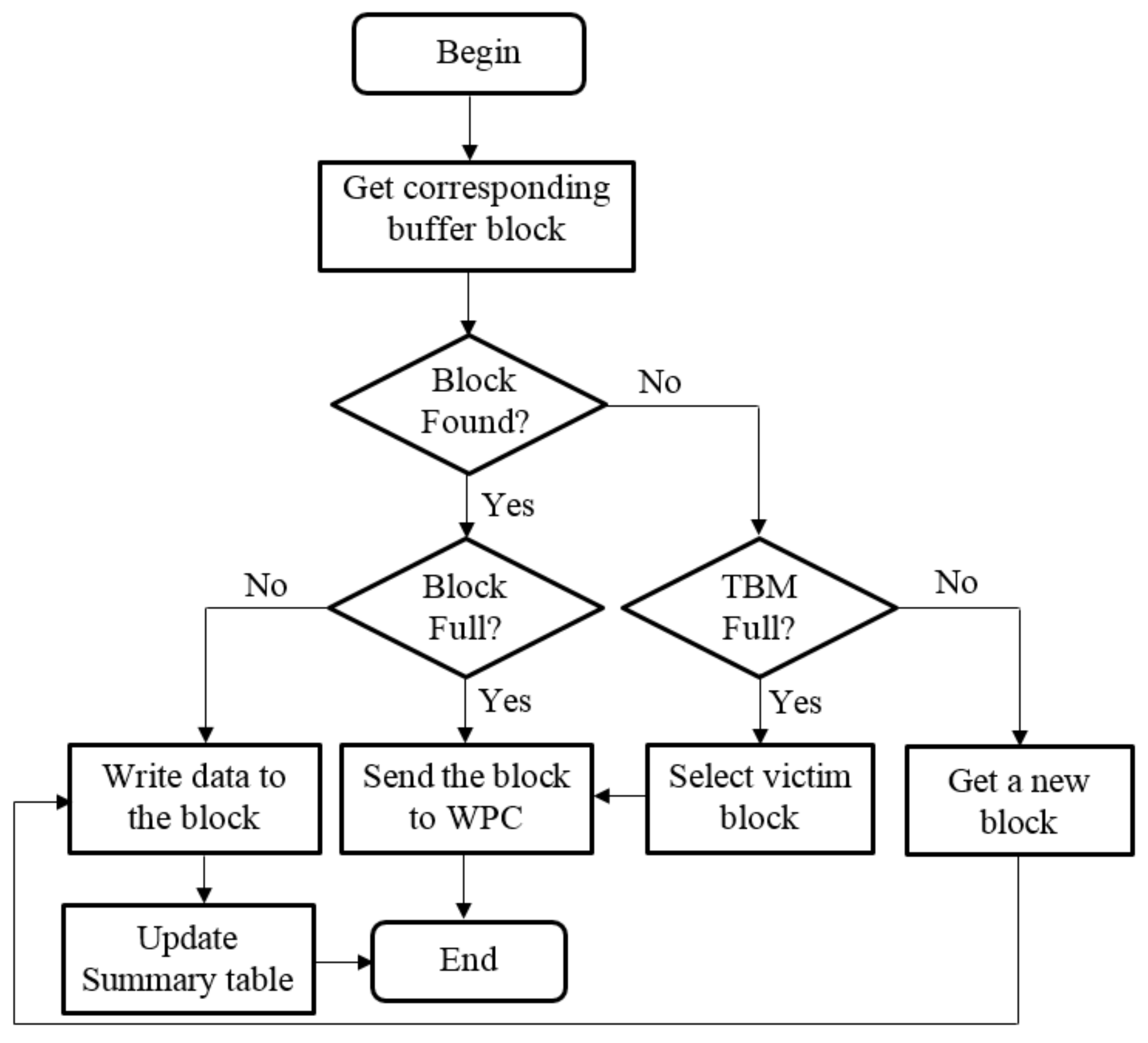
A flowchart of the process of writing data to the TBM is illustrated in Figure 4. When some nodes of the B-tree are updated, the WPCB-tree does not write them directly into flash memory; instead, these nodes are temporarily stored in the TBM as a requirement. This method is described as follows: Node pages (pages which store updated nodes) which have the same logical block number (LBN for short) are stored in the same buffer block. Upon receipt of a new writing request (node page), the WPCB-tree finds a buffer block corresponding to the node page and then writes the node page into the first free page of the buffer block if that block is not full.
On the other hand, if the corresponding buffer block is full, the WPCB-tree considers it as a victim block and sends a request to the WPC to hollow out the buffer block for the new writing request; the updated node is then written in the block. The procedure by which the WPC processes a victim block is presented in Section 3.3. In the case where there is no corresponding buffer block, the WPCB-tree checks whether the TBM is full or not. If the TBM is not full, the WPCB-tree writes the node page into an available buffer block. Otherwise, it selects a victim buffer block and handles the case in a similar manner as the case where the corresponding buffer block is full. After completely writing data to the buffer blocks, the Summary table is updated.
With this mechanism, blocks in the TBM will wear out from time to time, leading to a shortening of the life time of the flash memory. This is a weak point of the proposed scheme. However, instead, we can reduce the risk of losing the B-tree data by storing them on flash memory and not on a main-memory buffer. This is very useful for systems that want guaranteed high reliability.
Moreover, we can reduce the intensity of life shortening of the flash memory by not fixing the blocks used in the TBM, but also by the help of the wear leveling function. Generally, the wear leveling function selects a block with a low erase count whenever the system—for example, the TBM—needs a new block. Therefore, we believe that the proposed scheme is valuable in terms of providing high reliability, despite affecting the life time of the flash memory.
Figure 5 shows an example of storing data to the TBM. Assuming that nodes H, O, D, R, and G are modified, the logical page numbers 7, 14, 3, 17, and 6 of flash memory are updated, respectively. In this example, the node pages 7 and 6 have the same logical block number, so they are stored in the buffer block with (logic block number) LBN = 1.
Similarly, node pages 14, 3, and 17 are stored in the buffer blocks with LBN = 3, LBN = 0, and LBN = 4, respectively. Since the Summary table stores information on the buffer blocks, when selecting a victim block, the WPCB-tree scans the Summary table to obtain the victim block that has the smallest number of node pages, rather than scanning the whole buffer blocks.
Since all updated data are appended to the TBM, they are never lost in the case of power loss. When the system reboots after a crash, the WPCB-tree will merge all buffer blocks with the corresponding data blocks in flash memory so that all updated B-tree nodes are recovered and written to flash memory. This mechanism helps the WPCB-tree reduce the risk of data loss. It is an improvement compared with the buffer-based B-tree families. Therefore, it will be good for systems that want to be guaranteed high reliability.
3.3. Write Pattern Converter
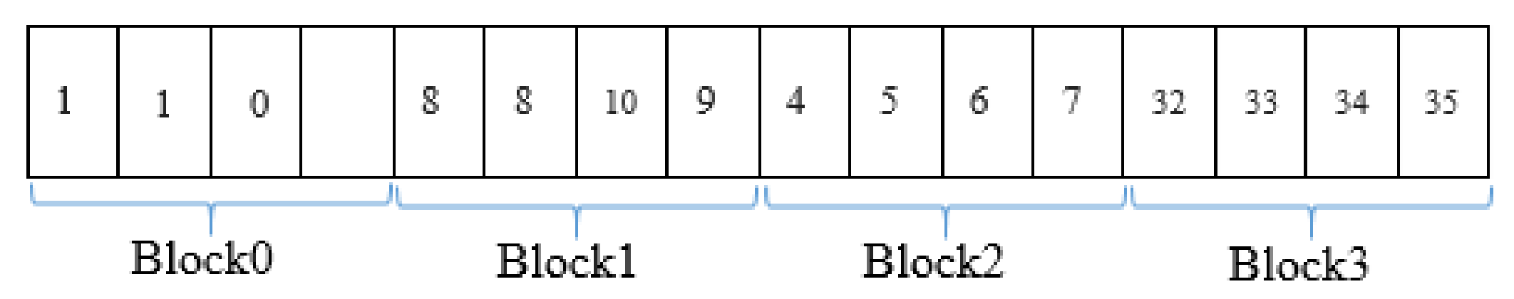
As soon as a writing request is received from the TBM, the WPC gets the victim block, and then converts from the random write pattern to a sequential write pattern before the data in the victim block is written into flash memory. The converting process is described as follows: The WPC scans the whole victim block; each page of the victim block is read once, starting from the last page back to the first page. If there is more than one node page with the same logic page number (LPN) in the victim block, only the most recently updated node page is considered as a sequential node page. Finally, all sequential node pages in the victim block are sequentially written into flash memory via FTL. Figure 6 illustrates an example of selecting the victim block. Assuming that the TBM has 4 buffer blocks, each block contains 4 pages, and a number of updated node pages which are written temporarily in each block. In this case, block 0 is chosen as the victim block because block 0 has the smallest number of updated node pages. In this victim block, there are two node pages with the same logic page number (LPN = 1). Therefore, the second one (the second with LPN = 1) is considered as a sequential node page because it is the most recently updated among the node pages with LPN = 1. After conversion, we have the sequential node pages list (0, 1). Finally, the two sequential node pages (node pages 0 and 1) are sequentially written into the flash. This scheme helps the WPCB-tree reduce the number of write operations.
4. WPCB-Tree Operations
This section presents the execution of WPCB-tree operations. WPCB-trees process insert operations and delete operations in the same way by storing updated pages in the TBM.
4.1. Insert Operation
The insert algorithm initially inserts a record into a corresponding node of the B-tree. This insert operation may decide whether a node split results in an update on the parent nodes or not. In the subsequent step, after the corresponding node of the B-tree is updated, the algorithm writes the updated node into the TMB. Finally, when the TBM sends a write request, the WPC converts the write pattern, enabling all updated nodes to be written into the flash.
The pseudo code of the insert algorithm is described in Algorithm 1. First, the insert algorithm of the WPCB-tree obtains the corresponding buffer block to the node page which is updated by invoking the getCorrBufferBlock function. Subsequently, depending on the status of the corresponding block (availability of a free page in the block) and the TBM (availability of a free buffer block in the TBM), the WPCB-tree performs a write operation into the TBM or sends a write request to the WPC. The final step of this algorithm is the storing of updated nodes of the B-tree into flash.
| Algorithm 1 Insertion algorithm |
| Input key k |
| 1 insert k into node on B-tree |
| 2 b <- getCorrBufferBlock() |
| 3 if exist(b) then |
| 4 if isfull(b) then |
| 5 s <- convertWritePattern(b) |
| 6 write(s) |
| 7 erase(b) |
| 8 endif |
| 9 else |
| 10 if isfull(TBM) then |
| 11 b <‐ victim block |
| 12 s <- convertWritePattern(b) |
| 13 write(s) |
| 14 erase(b) |
| 15 else |
| 16 b <- free block in TBM |
| 17 endif |
| 18 endif |
| 19 append(node, b, TBM) |
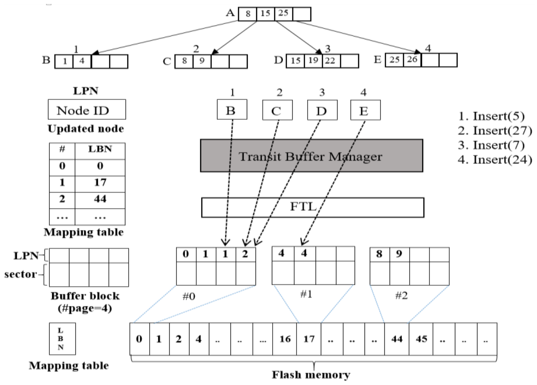
Figure 7 shows an example of inserting four records into the WPCB-tree and describes the process by which records are inserted into the WPCB-tree. In this example, we assume that each node of the B-tree can store a maximum of 4 keys and fits into a flash page. Another assumption is that a block has 4 pages (#page) and the TBM has 4 buffer blocks.
To begin, the WPCB-tree executes insert command #1 (Insert (5)) that inserts a record with key value 5 into node B which has LPN = 1. After updating node B, the WPCB-tree generates a request to write node page 1 into flash memory. The system then gets the LBN by using the equation LBN = LPN/#page = 1/4 = 0 and obtains the corresponding buffer block (block 0) in the TBM. Insert command #1 ends by storing updated node B in buffer block number 0 of the TBM, and then buffer block number 0 and LPN = 1 are written into the Summary table. The execution of the next two insert commands is the same as that of command #1. However, to perform command #4, which is an insertion of a record with key value 24, a different process for the insert algorithm is employed. This record will be inserted into node D, which has LPN = 3. Thus, the LBN and buffer blocks are 3 and 0, respectively. In this case, since it is already full (LPN = 0, 1, 1, 2), the buffer block number 0 is sent to the WPC for conversion from the random write pattern (0, 1, 1, 2) into a sequential write pattern (0, 1, 2), and these node pages are finally written into data blocks. After all node pages of the victim block are written into the data blocks, the victim block is erased for the new insert command (Insert (24)).
The most obvious benefit gained from this algorithm is to help the WPCB-tree avoid the erase-before-write blemish, and, in addition, ensure that data are always available even if a power failure occurs because all the updated data have been written into the flash memory. The worst case of algorithm 1 is to run the convertWritePattern() function. This function runs a loop from the first to the last page of the full block. Therefore, the complexity of Algorithm 1 is O(n), where n is the number of pages per block.
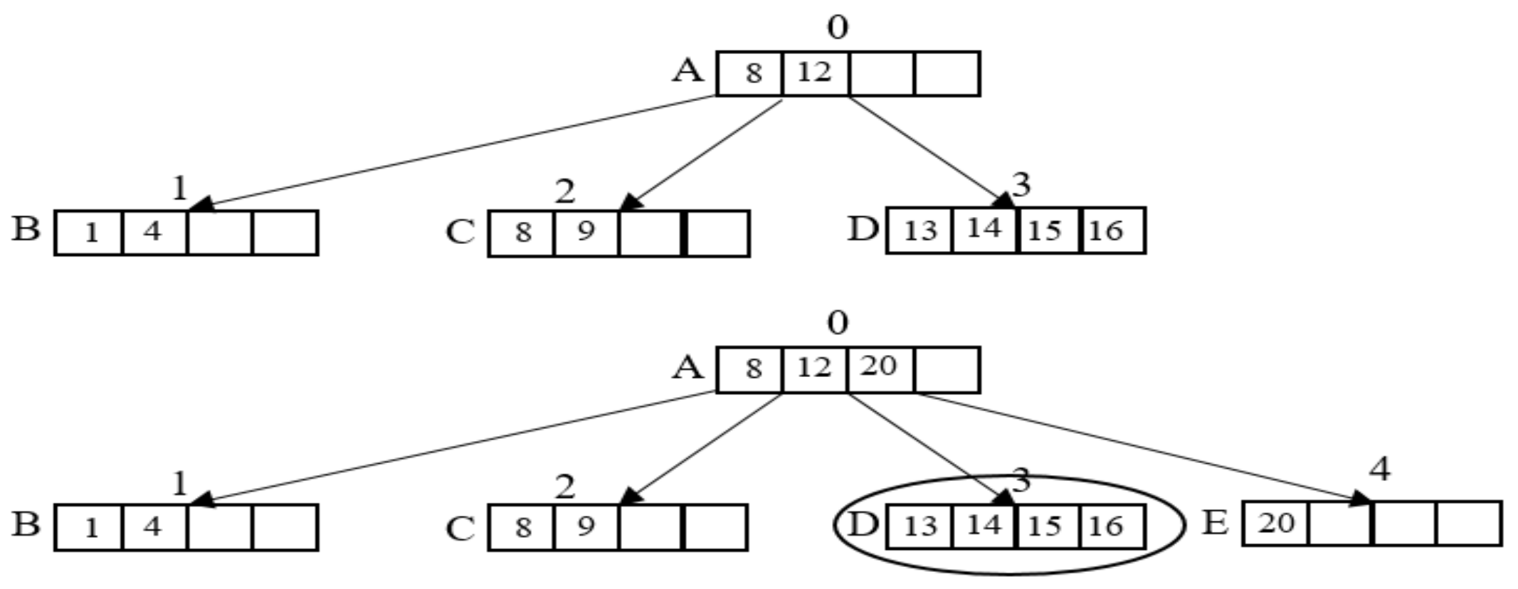
A special case of the insert operation is that all keys of a leaf node are inserted continuously. This is exemplified by inserting sequential records, as shown in Figure 8.
In this example, node D has 4 keys in which each key value, in turn, is 13, 14, 15, and 16. If a record with key = 20 is inserted into the general B-tree, the leaf node D is overflowing, and in consequence of that, the leaf node D is split into two nodes; this leads to a lot of flash operations being performed. Following on from the above points, the WPCB-tree performs these insert operations in a different way. The WPCB-tree will store the whole node D in the flash before the overflow occurs instead of splitting the leaf node D. Afterward, the new record is inserted into a new empty node E. Processing insert operations under this order allows the WPCB-tree to reduce the number of flash operations. Additionally, the page utilization increases because the utilization of the leaf is full in the WPCB-tree (not split), whereas the utilization of the leaf is half-full in the general B-tree after splitting the leaf node. As about 80–90% of the write pattern is sequential in the practical file systems [18,19], the performance of the WPCB-tree in practical systems will be enhanced.
4.2. Delete Operation
A delete operation is similar to an insert operation. All deleted records are performed on the WPCB-tree and updated nodes are then written into flash memory via the TBM, WPC, and FTL. At first, the WPCB-tree deletes records on the B-tree. After the updated nodes are written into the TBM, the WPC converts the random write pattern into a sequential write pattern and, lastly, the updated nodes are stored in flash memory. According to the general rule of a B-tree, if a node is underflowing, it will be merged with its neighbor nodes. However, most commercial database systems (e.g., Oracle [20,21]) allow underflows in nodes to happen so that performance degradation caused by frequent node merge operations can be avoided. Pursuant to this rule, the WPCB-tree accepts underflow nodes and does not deal with the merging node operation. When a node is empty after deleting keys, it is expelled from the tree. This also reduces the number of write operations in the flash.
4.3. Search Operation
The search operation of the WPCB-tree operates similarly to that of a conventional B-tree. To search a record with a specific key, the WPCB-tree traverses from the root node down to the leaf nodes to find the right leaf node. On the contrary, unlike the original B-tree, the WPCB-tree may have some nodes are currently in the TBM, and some read operations in the TBM may be invoked during the traversal process. When searching a record, the WPCB-tree reads either in the TBM or in the data blocks. By using the information on the Summary table, the target node may be read once from the TBM or may not. If there is no matching record in the TBM, the target node is read from the data blocks. Therefore, the WPCB-tree performs the search operation similarly to the original B-tree. Comprehensive information on different B-tree data structures is summarized in Table 2.
5. System Analysis
This section presents the analysis of the behaviors of the original B-tree and the WPCB-tree to assess the performance of the WPCB-tree. For easy analysis, we assumed that there are enough free blocks to perform I/O operations without any garbage collection. Table 3 summarizes the notation used in the analysis.
The performance of each variant is assessed as the read and write costs when inserting n records into the B-trees. Suppose that one node of the B-trees fits one page of flash memory and that the heights of the B-trees are equal and presented as h. An insert operation in both trees needs a search operation to find the target leaf node for the insertion. Therefore, the read cost of inserting one record is h × Or. For n records, the total read cost of insertions of trees is as in Equation (1). The costs for both trees are going to be the same.
While constructing an original B-tree, a number of the split, merge, and rotation operations are generated. Let Ns be the number of splits when inserting n records and let Nm, Nr be the number of merges and rotations when deleting n records. Each of these operations causes three additional writes since they update its parent node and sibling nodes. Therefore, the cost of additional split operations is Ns × 3 when inserting records and (Nm + Nr) × 3 when deleting records. In the WPCB-tree, since it adopts the overflow mechanism, the merge and rotation operations do not occur when deleting records and the split operations do not occur when inserting records with sequential key values. Therefore, there is no additional operations cost. Let us evaluate the total cost of flash operations in the case where n records are inserted into the B-tree and the WPCB-tree. Let m be the maximum number of entries that one node can have. Since half the space of the leaf node in the original B-tree is always filled after the leaf node is split when records are sequentially inserted, the split operation occurs whenever m/2 records are inserted. The split operation invokes additional write operations. In the WPCB-tree, when records are inserted in sequential key order, the node split operations are not performed. Moreover, merge and rotation operations are not performed when records are deleted in any order. However, the WPCB-tree needs to write updated nodes to the buffer blocks. Let M be the number of the merge operations that merge buffer blocks in the TBM with the corresponding data blocks when inserting n records. Therefore, when n records are sequentially inserted into the trees, the cost of these operations can be obtained as follows:
When n records are inserted in random key order, a number of node split operations are performed. Thus, the total cost of inserting n records with random key values into the trees is as follows:
When n records are deleted from the conventional B-tree, a number of node merge and rotation operations are executed. Every merge and rotation operation causes three additional operations. However, these operations are not performed in the WPCB-tree because the WPCB-tree allows underflow in nodes to happen. Thus, the total cost of deleting n records from the trees is as follows:
According to the WPCB-tree mechanism, every insertion, modification, and deletion causes a write operation that writes data to the buffer blocks. Since all data in the buffer block are sequentially written, which is much lower in overhead than the random write, the overhead of these write operations is relatively small. Although the cost of the WPCB-tree is increased because of the overhead of logging, the data are nonvolatile in return.
It is difficult to compare the write cost of the original B-tree and the WPCB-tree according to m, n, and M as variable values. This comparison will be present in Section 6.
6. Performance Evaluation
6.1. Simulation Methodology
This section shows the experimental results achieved by applying the proposed WPCB-tree and compares the WPCB-tree’s performance to that of other state-of-the-art flash-optimized indexing B-trees. All variant B-trees were performed on a NAND flash simulator FlashSim [22], which has the same characteristics as a real flash memory. The simulator could be configured with parameters such as the total capacity of NAND flash memory, the page size, and the number of pages in a block. This simulator was configured for flash memory with 2 KB page size and 128 KB block size. The simulator was deployed with the FAST FTL scheme. Every node of the WPCB-tree which fits one flash page had 128 entries, each of which contained a 4 byte integer key to search and a 4 byte pointer to point to the child node. The index keys were unique integers in the range of 1–1,000,000. The victim block was selected using the greedy algorithm. For a fair comparison, we implemented all B-tree variants on the same simulator. In the experiments using randomly generated keys, we repeated the same set of experiments five times and took the average of three values, discarding the maximum and the minimum values. For easy evaluation, we assumed that there are enough free blocks for the proposed method to perform I/O operations without any garbage collection.
The proposed scheme can be applied to any new 3D NAND flash memory seamlessly. The reason for this is that the WPCB-tree of our scheme is an intermedium software module existing between the application layer and FTL and, therefore, it is independent of the internal physical architecture of flash memory. For this reason, when conducting the performance evaluation, we used flash memory with 2 KB pages as a storage. These experimental settings enabled us to store the B-tree nodes into as many pages in flash memory as possible and, as a result, make a comparison among the several schemes more clearly. If we apply our scheme to multi level cell (MLC) or triple level cell (TLC) flash memory with 16 KB pages, we could store eight times as many B-tree nodes into a page of MLC or TCL flash memory as compared to single level cell (SLC) flash memory. In this case too, as mentioned above, all the modules in our scheme, such as the TBM and WPC, exist between the application layer and the FTL layer, operating exactly as they do in SLC flash memory. Therefore, our experimental results will still hold even if the technology is updated to a new one (i.e., MLC or TLC with 16 KB pages with multiplane access).
In the experiments, a ratio rs was used to control the value distribution of the inserted keys: when rs equals zero, all of the keys were randomly generated. If rs equals 1, the value of the inserted keys was in an ascending order. Consequently, if the value of rs equals 0.5, the values of one-half of the keys were in an ascending order, while the other keys were randomly generated.
To evaluate the performance of the WPCB-tree, we inserted and then retrieved the records, followed by an assessment of the WPCB-tree based on the total number of page reads, page writes, and block erases. We also estimated its efficiency from time-consumption and page utilization. To test the effectiveness, three experiments were performed. Experiment 1 dealt with the performance comparison between the WPCB-tree and other structure-modified B-tree variants with respect to flash operations, while Experiment 2 investigated the effects of the WPCB-tree based on creation and search time, and Experiment 3 assessed the usage efficiency of node space through the number of used blocks.
In order to have real workloads for all experiments, we built a B+-tree index on a hard disk drive and then collected I/O traces from logical sector numbers at the device driver level using a block tracing tool [23].
6.2. The Performance of the WPCB-Tree with Respect to Flash Operations
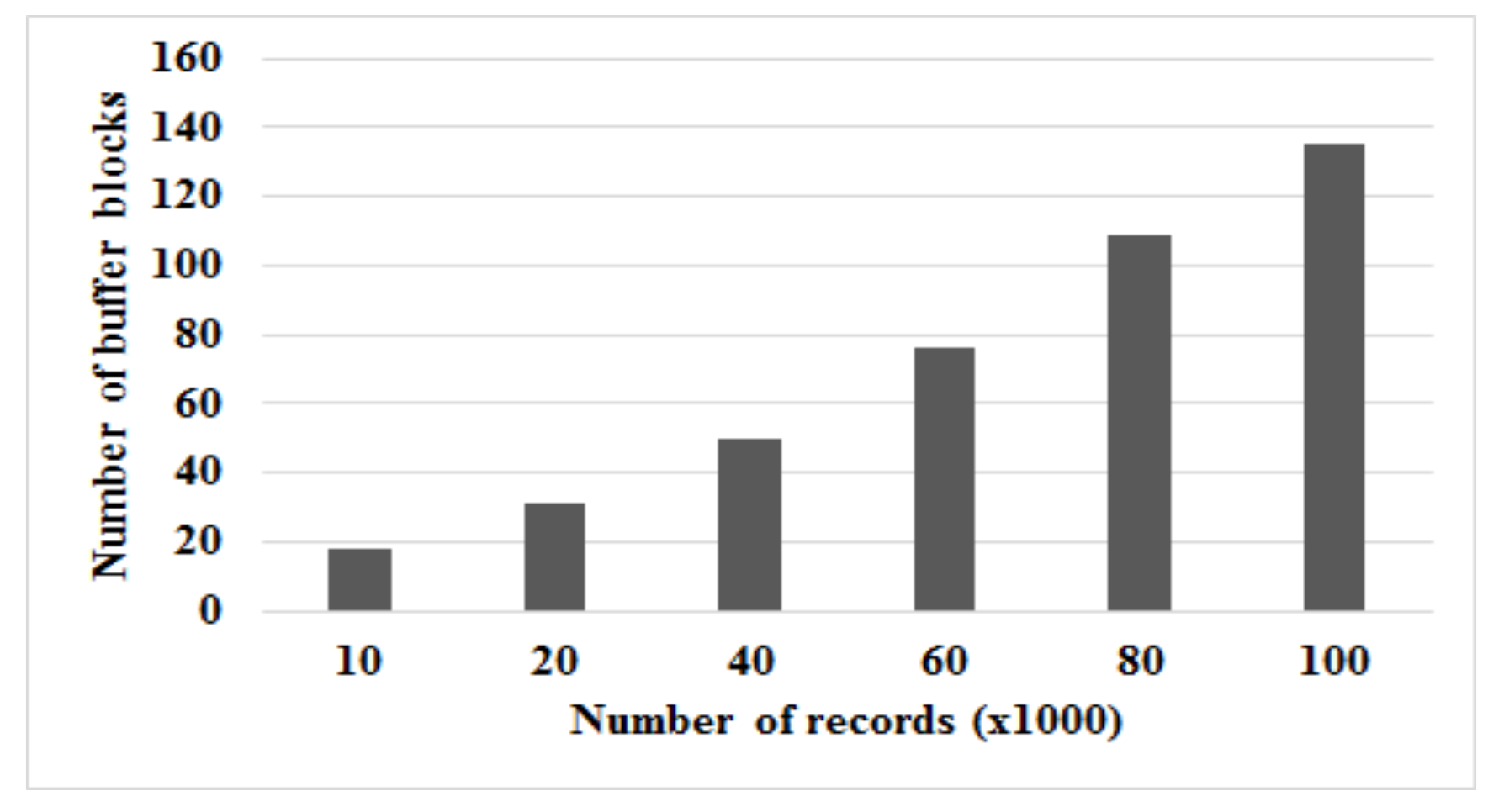
Before evaluating the performance of the WPCB-tree and comparing with other variant B-trees, we assessed the role of the TBM with respect to the WPCB-tree, enabling us to decide the optimal number of buffer blocks of the TBM, revealing that the performance of the WPCB-tree is the highest. Under the workloads adopted in this part of the experiment, records were inserted, modified, or deleted. Figure 9 shows the size of the TBM when the number of records inserted is changeable.
The number of buffer blocks of the TBM increases when the number of records increases. However, for an efficient trade-off between the flash memory space used for the TBM and the highest performance of the WPCB-tree, the optimal TBM size needs to be first obtained.
The experimental results of the WPCB-tree with various sizes of TBM are indicated in Figure 10.
It can be seen that when the number of the buffer blocks increases, the number of erase operations decreases. After the number of the buffer blocks reaches 128, no significant improvement was observed. Since further increasing the size of the TBM may consume some flash space, the recommended size of the TBM for the experiments was 128 buffer blocks. The number of required buffer blocks varies with the workload characteristics, including rs. To get the recommended size of the TBM, we performed the proposed system with different rs values and then calculated the average value of the TBM size.
Since all trees do not use a main memory writing buffer, their updated nodes are written directly to flash memory. The flash memory operations have great influence on the performance of these trees. Therefore, we compared the performance of the WPCB-tree with that of the dIPL B-tree, µ*-tree, and B+-tree to evaluate the effectiveness of the WPCB-tree based on the number of flash operations.
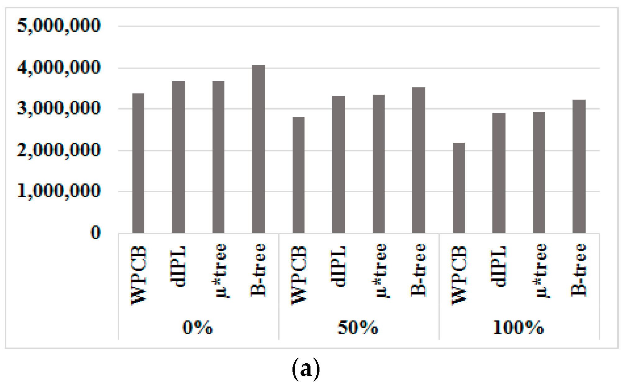
Figure 11a–c present the number of flash operations when 1,000,000 records with various key sequence ratios were inserted into the WPCB-tree, dIPL B-tree, µ*-tree, and B-tree, respectively.
In general, the WPCB-tree achieved the best results out of the trees on all three factors: page read, page write, and block erase. We emphasize erase operations in particular (Figure 11c) because the cost of this operation is much higher than that of the other operations.
From these experiments, we confirmed that the WPCB-tree efficiently reduced the number of flash operations. The WPCB-tree performed fewer flash operations than did the other trees in all cases. As can be seen from Figure 11c, the number of block erases by the WPCB-tree was approximately half of that of the other trees in all cases. Since the WPCB-tree used the whole empty buffer block to store temporarily inserted records, the time that the buffer block is full was delayed, so the merge operations did not occur frequently. Therefore, the number of flash operations was reduced. In contrast, the dIPL B-tree only used a part of blocks referred to as a log area to store inserted records. Because the size of the log area of the dIPL B-tree was smaller than that of a buffer block, the log areas were frequently full, causing the merge and erase operations to be executed more times than in the usual case. Similarly, the µ*-tree stored all nodes on the path from the root node to the leaf node in a single page. Thus, as soon as the height of the tree increased, the merge and erase operations increased as well, resulting in the quick fulfillment of that single page.
In particular, in case where all inserted records were inserted sequentially (rs = 1), the number of flash operations generated by the WPCB-tree was reduced significantly compared to that of the other cases. Moreover, the WPCB-tree performed much fewer erase operations than the other trees did, i.e., one-third compared to the B-tree. In this case, the WPCB-tree used overflow, which does not split a fulfilled node because all keys are inserted sequentially. When a node was fulfilled by sequentially ordered keys, the node was directly written into flash instead of splitting as the normal B-tree did, thus reducing the number of split operations. This mechanism helped the WPCB-tree significantly decrease the number of flash operations.
6.3. The Performance of the WPCB-Tree with Respect to Time Consumption
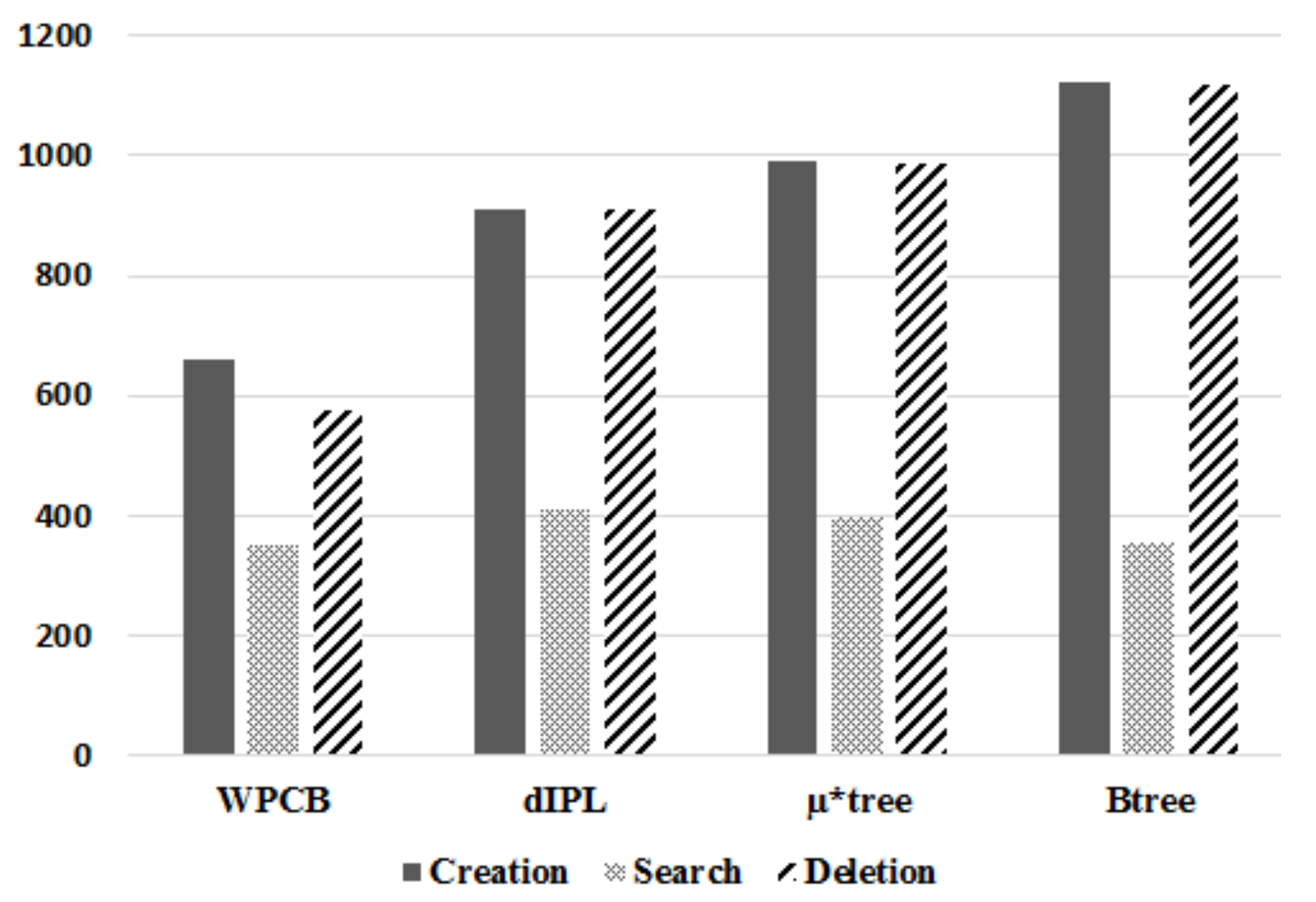
In the second experiment, our comparison between the WPCB-tree and the other trees was based on creation time and search time. The creation time in this experiment included the time complexity of the insert, delete, and search operations. As the number of records increases, the number of flash operations also grows; thus, time consumption is increased. To compare the performance of the WPCB-tree and other variants of B-tree, we performed one million insert operations on each tree. The B-tree index structures were created by record insertions. For a deletion test, we used workloads mixed with insertions and deletions of records for all B-tree indexes. In other words, the workloads consisted of insertions, searches, and deletions.
As presented in Figure 12, the required time to build the WPCB-tree was lower than other trees because the WPCB-tree used the write pattern converter to convert the random write pattern into a sequential write pattern. This mechanism helped the WPCB-tree reduce the creation time by approximately 38–67% in comparison with the other trees. Concretely, the WPCB-tree was about 38.7%, 50.9%, and 67.2% faster than the dIPL, µ*-tree, and B-tree, respectively. Moreover, since the WPCB-tree used an overflow mechanism, the number of pages occupied by the WPCB-tree was much fewer than that of the other trees, improving the garbage collection overhead of the WPCB-tree.
For the search time, the WPCB-tree was about 14.3% and 11.1% faster than the dIPL B-tree and µ*-tree, respectively, because the WPCB-tree quickly found the right records by using information on Summary table and invoked fewer additional operations than the other trees did. For the dIPL B-tree, since updated records were stored in the log area, scanning the log area to find a specific record consumed time. So, the dIPL took a long time to build the tree. Similarly, the µ*-tree used more pages to store records; therefore, to reach the right records, more pages were read, leading to time being consumed.
Since the WPCB-tree accepted underflowing nodes and did not deal with node merge operations, its consumed time for delete operations was much lower than that of the other B-tree variants. The WPCB-tree was built 57.7%, 71.2%, and 93.4% faster than the dIPL, µ*-tree, and B-tree were, respectively.
6.4. Page Utilization
This section depicts the results of experiments based on node utilization to assess the overflow mechanism which does not split the overflow leaf nodes if all key values of the leaf nodes are inserted contiguously and does not merge when the leaf nodes are underflowing. To evaluate this mechanism, we conducted Experiment 3, in which 1,000,000 records with various key sequence ratios were inserted. Under the workloads adopted in this part of the experiment, records were inserted only.
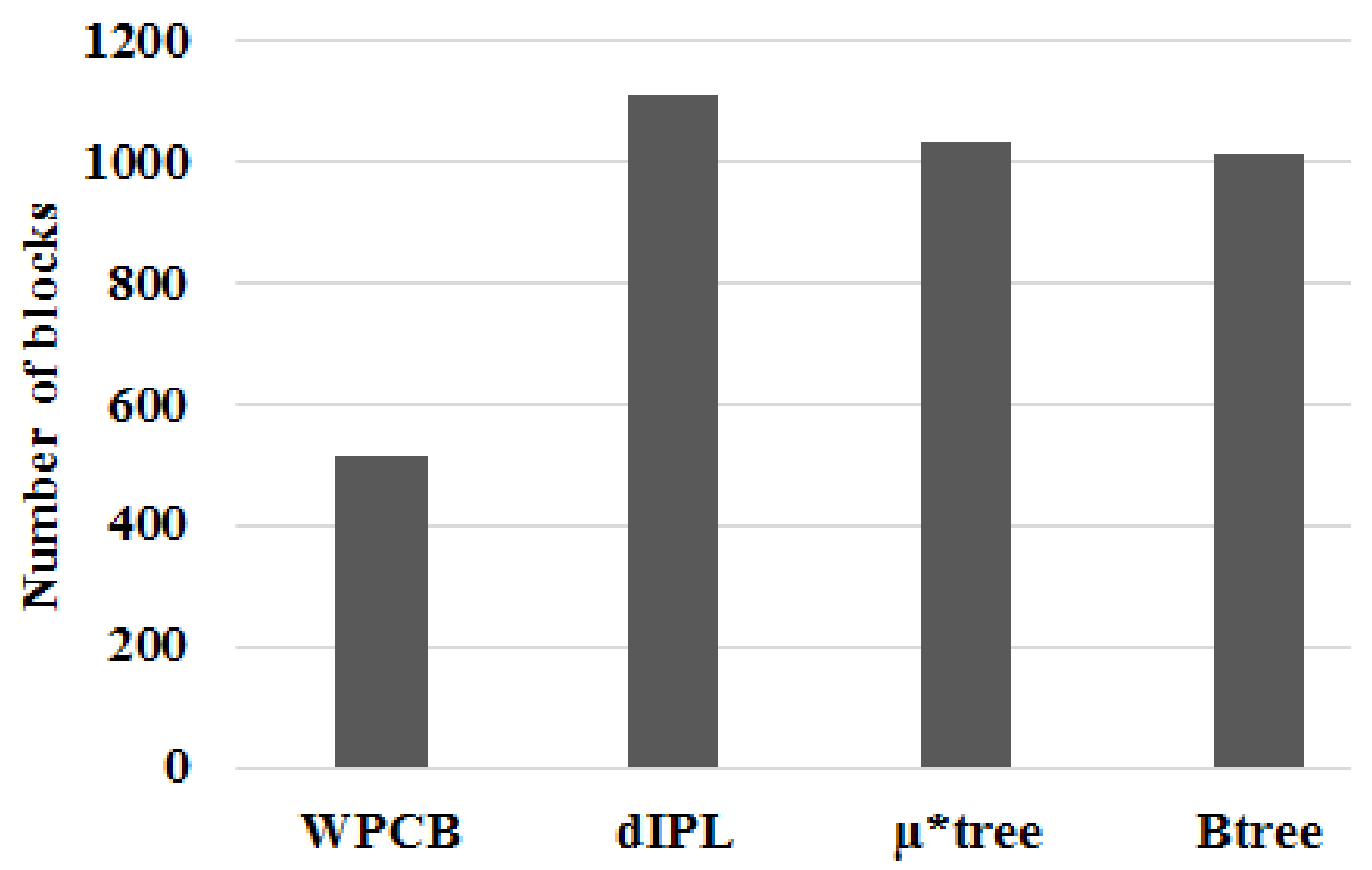
Figure 13 illustrates the number of flash blocks needed to store index trees when records were inserted sequentially (the ratio was 1). It is apparent that the number of blocks that the WPCB-tree used to store indices was approximately half of that used by the other three trees. The dIPL B-tree needed the highest block number because it used some pages of each block to store log records. In this case, all key values of the leaf nodes were in contiguous order; this helped the WPCB-tree to not split the overflow leaf nodes. As a result, the WPCB-tree used fewer blocks than the other trees did. Moreover, the leaf nodes of the WPCB-tree were completely full, whereas those of the other trees were half-full because they were always split when overflowed. As assumed at the beginning of this study, each page could store one node; thus, if the number of nodes increased, the required number of blocks increased, too.
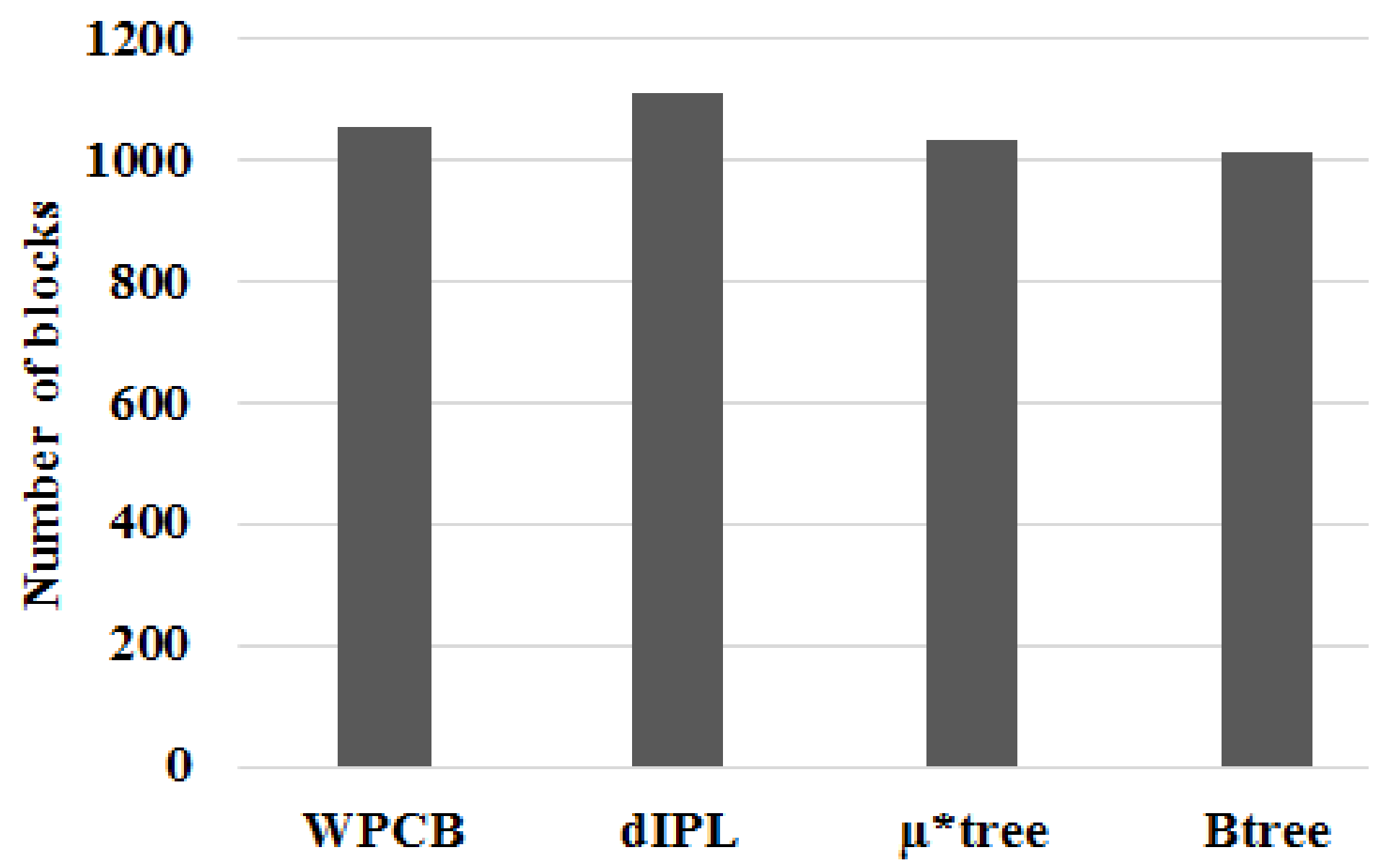
Similarly, the WPCB-tree needed fewer flash blocks than the other trees did when the ratio was 0.5 (see Figure 14). Some nodes, in this case, had contiguous keys because of sometimes being inserted sequentially. Since there were many nodes, which did not split (full), the number of blocks of the WPCB-tree was reduced.
From Figure 15, we can see that the number of blocks that the WPCB-tree needed to store key values was lower than that of dIPL and a bit higher than that of the conventional B-tree and µ*-tree when the records were inserted randomly (the ratio was 0). In this case, the WPCB-tree did not have any overflow leaf nodes containing contiguous key values, and all the overflow nodes were split. Besides that, the WPCB-tree needed some more buffer blocks to store temporary records which were not yet merged with the corresponding data blocks. Thus, the number of blocks needed by the WPCB-tree was increased compared with the rs = 0.5 and rs = 1 cases.
7. Conclusions
Flash memory and B-tree index structures are widely used for embedded systems, personal computers, and large-scale server systems. Due to hardware restrictions, the performance of flash memory could significantly deteriorate when directly implementing the B-tree. In this paper, we propose a new B-tree index structure using a write pattern converter. The proposed system not only helps to improve the performance of flash memory storage systems but also enhances the page utilization of the flash memory by using an “overflow” mechanism. Moreover, using a write pattern converter to convert the write pattern from random to sequential allows the flash memory to reduce a lot of costs from the additional overhead of a random write pattern. The experimental results showed that the WPCB-tree yields a better performance than that of other trees. In particular, the WPCB-tree is able to ensure that data is not lost in the case of power failure while creating a B-tree index structure by using buffer blocks (TBM). This is very useful for systems that require guaranteed high reliability.
Acknowledgments
This research was supported by Basic Science Research Program through the National Research Foundation of Korea (NRF) funded by the Ministry of Education (NRF-2015R1D1A1A01056593).
Author Contributions
Dong-Joo Park provided the main idea for this paper, designed the overall architecture of the proposed algorithm, supervised the work, and revised the paper. Van Phi Ho conducted the test data collection, designed the experiment, and wrote the paper.
Conflicts of Interest
The authors declare no conflict of interest.
References
- Chung, T.-S.; Park, D.-J.; Park, S.; Lee, D.-H.; Lee, S.-W.; Song, H.-J. A Survey of Flash Translation Layer. J. Syst. Archit. 2009, 55, 332–343. [Google Scholar] [CrossRef]
- Lee, S.-W.; Moon, B.; Park, C.; Kim, J.-M.; Kim, S.-W. A Case for Flash Memory SSD in Enterprise Database Applications. In Proceedings of the SIGMOD’08 Proceedings of the 2008 ACM SIGMOD International Conference on Management of Data, Vancouver, BC, Canada, 9–12 June 2008; pp. 1075–1086. [Google Scholar]
- Kingston Technology Corporation. Flash Memory Guide. 2012. Available online: media.kingston.com/pdfs/MKF-_283.1_Flash_Memory_Guide_EN.pdf (accessed on 10 April 2012).
- Pratibha, S; Mrs., Suvarna. Efficient Flash Translation layer for Flash Memory. Int. J. Sci. Res. Publ. 2013, 3, 1646–1652. [Google Scholar]
- Li, Y.; Quader, K.N. NAND Flash Memory: Challenges and Opportunities. Computer 2013, 46, 23–29. [Google Scholar] [CrossRef]
- Ma, D.; Feng, J.; Li, G. LazyFTL: A Page-Level Flash Translation Layer Optimized for NAND Flash Memory. In Proceedings of the SIGMOD’11 Proceedings of the 2011 ACM SIGMOD International Conference on Management of Data, Athens, Greece, 12–16 June 2011; pp. 1–12. [Google Scholar]
- Ma, D.; Feng, J.; Li, G. A Survey of Address Translation Technologies for Flash Memories. ACM Comput. Surv. 2014, 46, 36. [Google Scholar] [CrossRef]
- Lee, H.-S.; Yun, H.-S.; Lee, D.-H. HFTL: Hybrid Flash Translation Layer based on Hot Data Identification for Flash Memory. IEEE Trans. Consum. Electron. 2009, 55, 2005–2011. [Google Scholar] [CrossRef]
- Gupta, A.; Kim, Y.; Urgaonkar, B. DFTL: A Flash Translation Layer Employing Demand-based Selective Caching of Page-level Address Mappings. In Proceedings of the 14th International Conference Architectural Support for Programming Languages and Operating Systems, Washington, DC, USA, 7–11 March 2009; pp. 229–240. [Google Scholar]
- Park, D. CFTL: An Adaptive Hybrid Flash Translation Layer with Efficient Caching Strategies. In Proceedings of the Modeling, Analysis & Simulation of Computer and Telecommunication Systems (MASCOTS), Singapore, 25–17 July 2011. [Google Scholar]
- Birrell, A.; Isard, M.; Thacker, C.; Wobber, T. A Design for High-Performance Flash Disks. ACM SIGOPS Oper. Syst. Rev. 2007, 41, 88–93. [Google Scholar] [CrossRef]
- Batory, D.S. B+-Trees and Indexed Sequential Files: A Performance Comparison. In Proceedings of the 1981 ACM SIGMOD International Conference, Ann Arbor, MI, USA, 29 April–1 May 1981; pp. 30–39. [Google Scholar]
- Ho, V.; Park, D.-J. A Survey of the-State-of-the-Art B-tree Index on Flash Memory. Int. J. Softw. Eng. Its Appl. 2016, 10, 173–188. [Google Scholar] [CrossRef]
- IBM Research Report. The Fundamental Limit of Flash Random Write Performance: Understanding, Analysis and Performance Modelling. Available online: http://domino.watson.ibm.com/li-brary/Cyberdig.nsf/home (accessed on 31 March 2010).
- Kim, H.; Ahn, S. BPLRU: A buffer management scheme for improving random writes in flash storage. In Proceedings of the FAST’08 Proceedings of the 6th USENIX Conference on File and Storage Technologies, San Jose, CA, USA, 26–29 February 2008. Article No. 16. [Google Scholar]
- Gb F-die NAND Flash. Available online: http://www.mt-system.ru/sites/default/files/docs/samsung/k9f1g08u0f_1.0.pdf (accessed on 26 July 2016).
- Park, D.-J.; Choi, H.-G. Efficiently Managing the B-tree using Write Pattern Conversion on NAND Flash Memory. J. KIISE Comput. Syst. Theory 2009, 36, 521–531. [Google Scholar]
- Roselli, D.; Lorch, J.R.; Anderson, T.E. A Comparison of File System Workloads. In Proceedings of the 6th USENIX Conference on File and Storage Technologies, San Diego, CA, USA, 18–23 June 2000; pp. 41–54. [Google Scholar]
- Leung, A.W.; Pasupathy, S.; Goodson, G.; Miller, E.L. Measurement and Analysis of Large Scale Network File System Workloads. In Proceedings of the ATC’08 USENIX 2008 Annual Technical Conference, Boston, MA, USA, 22–27 June 2008; pp. 213–226. [Google Scholar]
- Dillon, S.; Beck, C.; Kyte, T.; Kallman, J.; Rogers, H. Beginning Oracle Programming; Wrox Press: Birmingham, UK, 2003. [Google Scholar]
- Ponnekanti, N.; Kodavalla, H. Online Index Rebuild. In Proceedings of the SIGMOD/PODS’00 ACM International Conference on Management of Data and Symposium on Principles of Database Systems, Dallas, TX, USA, 15–18 May 2000; pp. 529–538. [Google Scholar]
- Kim, Y.; Tauras, B.; Gupta, A.; Urgaonkar, B. FlashSim: A Simulator for NAND Flash-based Solid-State Drives. In Proceedings of the First International Conference on Advances in System Simulation, Porto, Portugal, 20–25 September 2009; pp. 125–131. [Google Scholar]
- Axboe, J.; Brunelle, A.D. Blktrace User Guide. 2007. Available online: http://kernel.org/pub/linux/kernel/people/axboe/blk-trace/ (accessed on 5 September 2006).
Figure 1.
B-tree on block mapping flash memory.
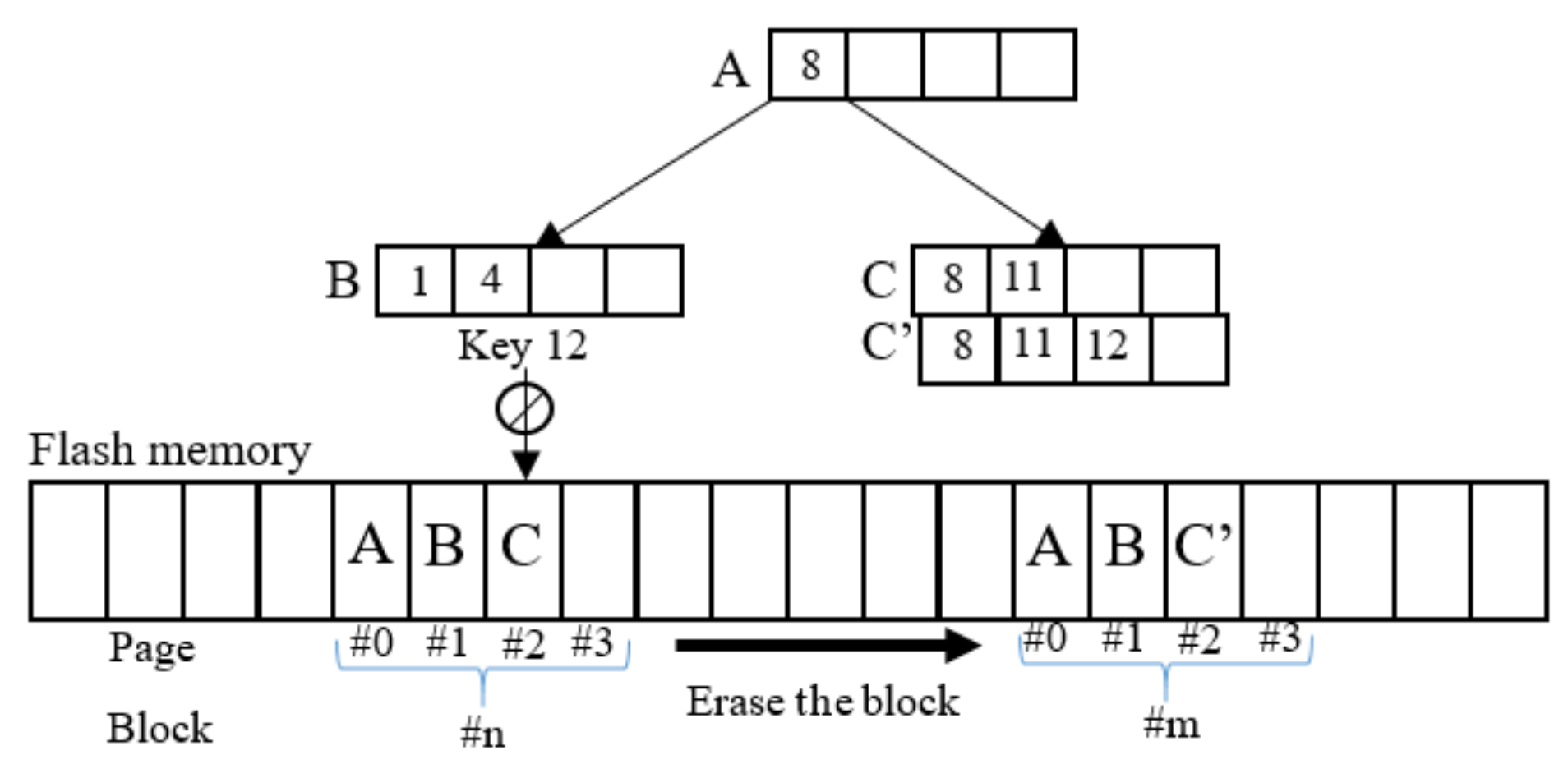
Figure 2.
The cost of write patterns [17].
Figure 2.
The cost of write patterns [17].
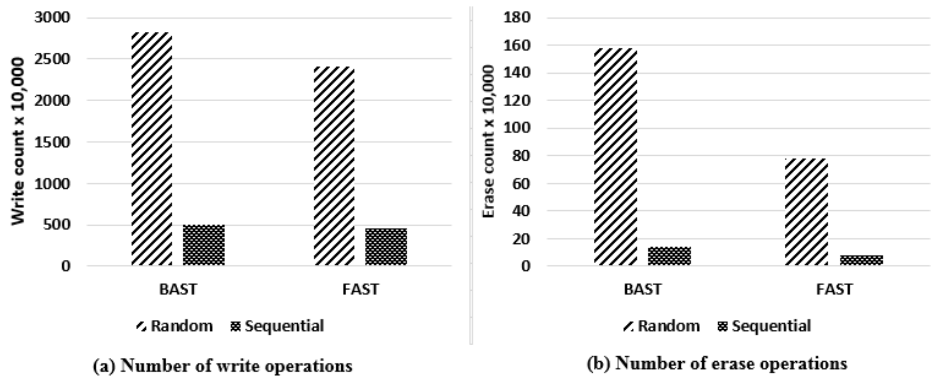
Figure 3.
Architecture of the write pattern converter B-tree (WPCB-tree).
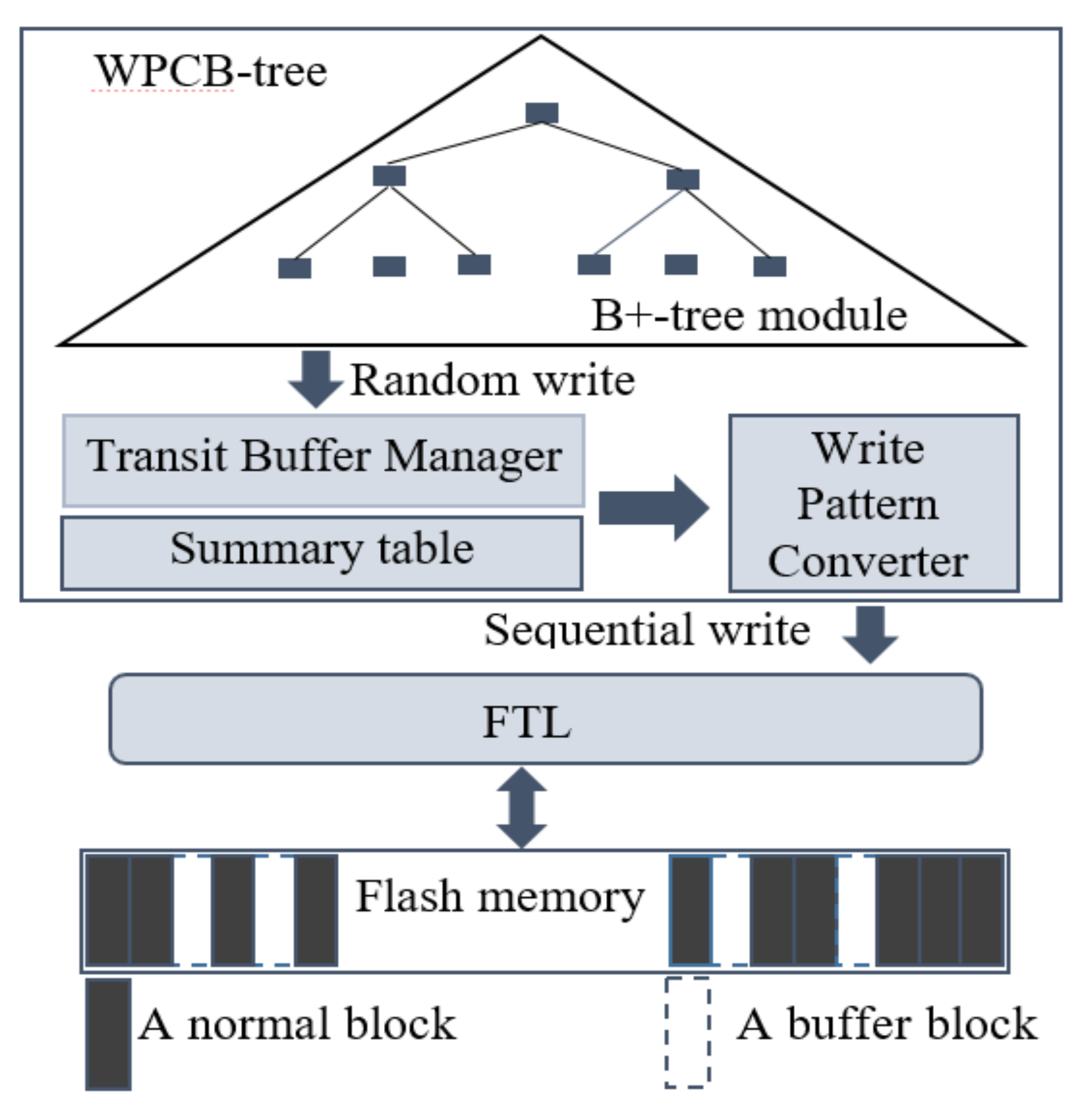
Figure 4.
The process of writing data to the Transit Buffer Manager (TBM).

Figure 5.
An example of the Transit Buffer Manager.
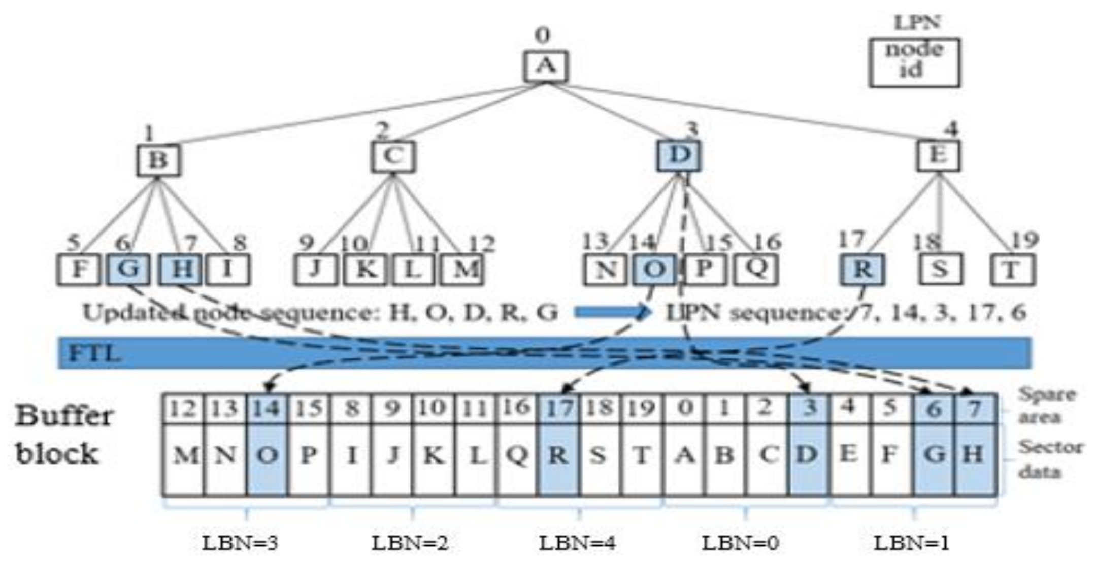
Figure 6.
Example of selecting the victim block.

Figure 7.
Insertion of records.

Figure 8.
Example of sequential insertions.

Figure 9.
Variable size of the TBM.

Figure 10.
Effect of the TBM size.
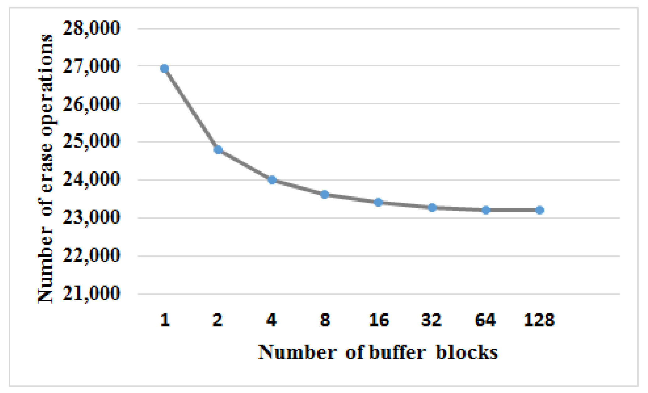
Figure 11.
(a) Number of page reads; (b) Number of page writes; (c) Number of block erases.

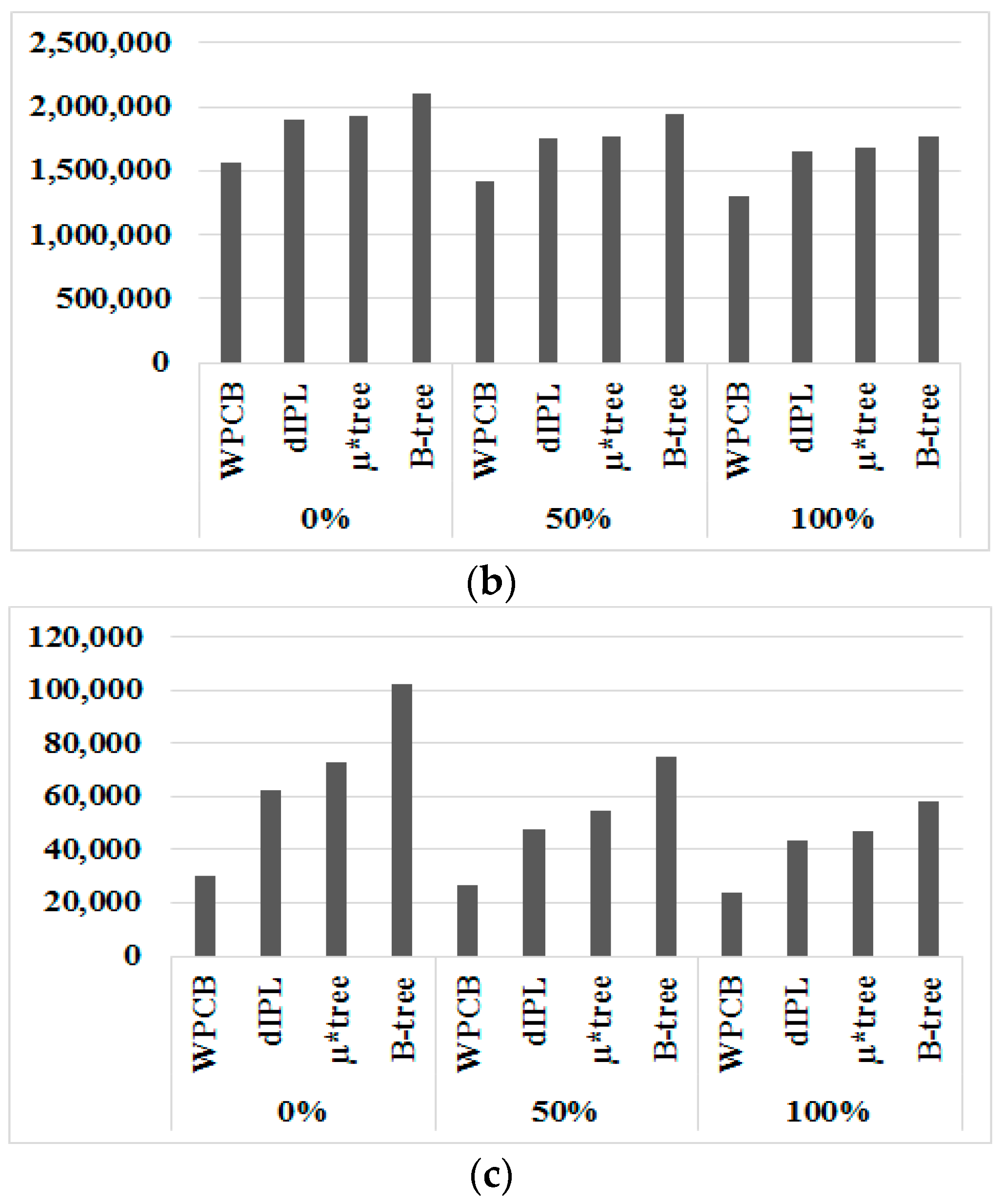
Figure 12.
Total elapsed time for one million records inserted and deleted.

Figure 13.
The number of flash blocks needed when the ratio rs = 1.

Figure 14.
The number of flash blocks needed when ratio rs = 0.5.
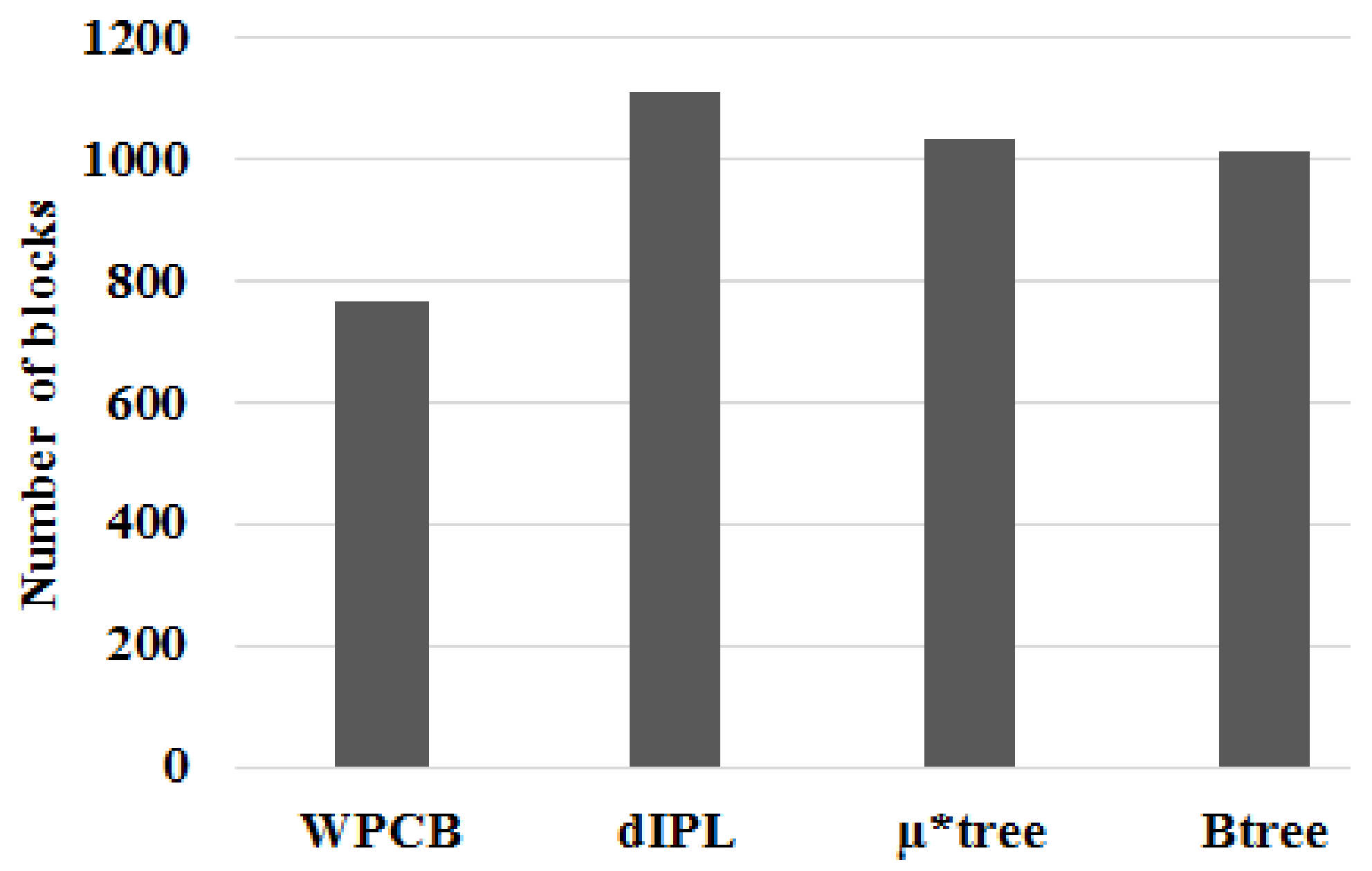
Figure 15.
The number of flash blocks needed when ratio rs = 0.


Table 1.
The cost of write and read operations [16].
Table 1.
The cost of write and read operations [16].
| Random Write | Random Read | Sequential Write | Sequential Read |
|---|---|---|---|
| 400 µs | 25 µs | 200 µs | 25 ns |
Table 2.
The Characteristics of B-tree variants.
| Name | Resource of Buffer | Number of Node per Page | Write Operations | Read Operations | Split Operations | Merge Operations | Risk Of Data Loss | Page Occupancy |
|---|---|---|---|---|---|---|---|---|
| BFTL | Main memory | Many | Reduced | Increased | Normal | Normal | Yes | Low |
| IBSF | Main memory | One | Reduced | Normal | Normal | Normal | Yes | Normal |
| LA-tree | Flash memory | One | Reduced | Increased | Normal | Normal | No | Normal |
| MB-tree | Main memory | One | Reduced | Normal | Normal | Normal | Yes | Normal |
| µ-tree | No | Many | Normal | Normal | Frequently | Normal | No | High |
| µ*-tree | No | Many | Normal | Normal | Frequently | Normal | No | High |
| IPL | Flash memory | One | Increased | Increased | Normal | Frequently | No | High |
| dIPL | Flash memory | One | Increased | Increased | Normal | Frequently | No | High |
| WPCB | Flash memory | One | Increased | Normal | Reduced | No | No | Reduced |
Table 3.
Notation Summary.
| Symbols | Definitions |
|---|---|
| n | number of records |
| h | height of B-trees |
| Or | cost of a flash read operation |
| Ow | cost of a flash random write operation |
| Osw | cost of a flash sequential write operation |
| m | maximum entries one node can have |
| Ns | number of split operations |
| Nm | number of merge operations |
| Nr | number of rotation operations |
| M | number of block merge operations |
© 2018 by the authors. Licensee MDPI, Basel, Switzerland. This article is an open access article distributed under the terms and conditions of the Creative Commons Attribution (CC BY) license (http://creativecommons.org/licenses/by/4.0/).
Share and Cite
MDPI and ACS Style
Ho, V.P.; Park, D.-J. WPCB-Tree: A Novel Flash-Aware B-Tree Index Using a Write Pattern Converter. Symmetry 2018, 10, 18. https://doi.org/10.3390/sym10010018
AMA Style
Ho VP, Park D-J. WPCB-Tree: A Novel Flash-Aware B-Tree Index Using a Write Pattern Converter. Symmetry. 2018; 10(1):18. https://doi.org/10.3390/sym10010018
Chicago/Turabian StyleHo, Van Phi, and Dong-Joo Park. 2018. "WPCB-Tree: A Novel Flash-Aware B-Tree Index Using a Write Pattern Converter" Symmetry 10, no. 1: 18. https://doi.org/10.3390/sym10010018
Note that from the first issue of 2016, this journal uses article numbers instead of page numbers. See further details here.