An Online Algorithm for Dynamic NFV Placement in Cloud-Based Autonomous Response Networks
by
 , , and
Leonardo Ochoa-Aday
1,* ,
,
Cristina Cervelló-Pastor
1,
Adriana Fernández-Fernández
1 and
Paola Grosso
2 1
Department of Network Engineering, Universitat Politècnica de Catalunya (UPC), Esteve Terradas, 7, 08860 Castelldefels, Spain
2
System and Network Engineering (SNE) Research Group, Universiteit van Amsterdam (UvA), Science Park, 904, 1098 XH Amsterdam, The Netherlands
*
Author to whom correspondence should be addressed.
Symmetry 2018, 10(5), 163; https://doi.org/10.3390/sym10050163
Submission received: 30 March 2018
/
Revised: 3 May 2018
/
Accepted: 10 May 2018
/
Published: 15 May 2018
(This article belongs to the Special Issue Advanced in Artificial Intelligence and Cloud Computing)
Abstract
:Autonomous response networks are becoming a reality thanks to recent advances in cloud computing, Network Function Virtualization (NFV) and Software-Defined Networking (SDN) technologies. These enhanced networks fully enable autonomous real-time management of virtualized infrastructures. In this context, one of the major challenges is how virtualized network resources can be effectively placed. Although this issue has been addressed before in cloud-based environments, it is not yet completely resolved for the online placement of virtual machines. For such a purpose, this paper proposes an online heuristic algorithm called Topology-Aware Placement of Virtual Network Functions (TAP-VNF) as a low-complexity solution for such dynamic infrastructures. As a complement, we provide a general formulation of the network function placement using the service function chaining concept. Furthermore, two metrics called consolidation and aggregation validate the efficiency of the proposal in the experimental simulations. We have compared our approach with optimal solutions, in terms of consolidation and aggregation ratios, showing a more suitable performance for dynamic cloud-based environments. The obtained results show that TAP-VNF also outperforms existing approaches based on traditional bin packing schemes.
1. Introduction
The evolution of information and communication technologies (i.e., cloud computing, Internet of Things, 5G, etc.) has enabled a large market of applications and network services for a massive number of users connected to the Internet [1]. To overcome these ever-increasing demands, network operators will require emerging solutions to effectively manage their network resources in a dynamic and flexible manner. In this regard, novel technologies such as Network Function Virtualization (NFV) and Software-Defined Networking (SDN) have been identified as promising approaches to reduce the management complexity in such network infrastructures.
Today’s networks rely on a mixture of service functions (i.e., load balancing, network address translation, firewall, etc.) implemented on proprietary hardware appliances. In this context, NFV transforms current network services into Virtual Network Functions (VNF), replacing vendor-specific hardware implementations by software embedded into commodity servers [1]. As a result, VNFs can now be placed, or instantiated, within a Virtual Machine (VM) that consumes different resources (e.g., CPU, memory, etc.) from servers out of the special-purpose domain. On the other hand, SDN is a network design that centralizes the control plane functions of underlying forwarding devices in a new network entity, called the SDN controller [2]. This approach evolves traditional network infrastructures from configurable to programmable. Consequently, it fully leverages the flexibility of a fine-grained traffic management in all forwarding domains. Although SDN and NFV are independent, both approaches potentially reduce the Capital Expenditure (CAPEX) and Operational Expenditure (OPEX) of network operators.
The envisioned convergence between networking and IT industries is now possible through the advances in cloud computing and SDN/NFV technologies. Driven by this reality, companies aim to use the flexibility provided by these technologies to mitigate CAPEX and OPEX in self-managing computing systems. This approach, referred to as Autonomic Network Management (ANM), enables networks to work in a totally unsupervised manner, dynamically adapting their behaviors to meet high-level application goals [3]. ANM is a special case of autonomic computing, which is a computing initiative inspired from the autonomous nervous system of the human body [4]. Compared to autonomic system management, the autonomic management of networks is more complex. This is due to the variety of management standards, network protocols and the presence of different vendors on heterogeneous and interconnected management domains.
In that direction, Autonomous Response Networks (ARN) propose an enhanced network design that uses the latest techniques in SDN and NFV to fully enable autonomous real-time management of network infrastructures. This framework takes into account high-level operators’ objectives such as enhanced fault-tolerance, cyber attack mitigation and performance guarantees, among many others. In this regard, one of the major challenges is how virtualized network resources can be efficiently and dynamically allocated.
Although autonomic management has been identified as the next generation of network management [3], we identify a lack of proposals that adopt the ANM paradigm into an NFV/SDN network infrastructure. In this context, Secure Autonomous Response Networks (SARNET) [5] is a research project that investigates how detection and protection concepts, using NFV-/SDN-based technologies, can provide autonomous protection against various types of cyber attacks [6].
This research evaluates the suitability of different VNF placement strategies using the Service Function Chaining (SFC) concept in ARNs. In this study, we consider both static (offline) and dynamic (online) scenarios. The offline scenario is considered as an ARN system aware of the full set of SFC requests. On the other hand, the online scenario considers an ARN system, with a set of already deployed SFCs, where new incoming SFC requests are processed in a one-by-one modality. As a complement, we also derive analytical expressions for two evaluation metrics to assess the network performance of the identified placement solutions.
Specifically, the contributions of this paper are summarized as follows:
- Formulation of the network function placement and chaining problem as an Integer Linear Programming (ILP) for the offline approach.
- Heuristic algorithm based on the WORSTFIT approach (i.e., optimal solution of the bin packing problem) to efficiently place the VNFs in an online scenario.
- Evaluation parameters denoted as consolidation and aggregation to assess the impact of network topology and system demands (i.e., requested SFCs) on the placement solutions.
The remainder of this paper is organized as follows. In Section 2, we discuss some related works. After describing the system model in Section 3, we formulate the resource allocation problem in Section 4. Afterwards, we define the proposed online heuristic algorithm in Section 5. We then introduce two evaluation metrics in Section 6 and present the considered simulation setup in Section 7. We discuss some experimental results in Section 8. Lastly, we summarize our findings in Section 9.
2. Related Works
Although comprehensive surveys were already given in [7,8], in this section, we identify some related works according to the research topics covered by this study.
Different goals can be targeted to place the VNFs into the network graphs, resulting in different placement solutions. In [9], the authors performed a Pareto set analysis to investigate the possible trade-offs between different optimization objectives (i.e., maximizing data rate on network links and minimizing number of used nodes or latency of created paths). To that end, they proposed an MILP strategy for finding the placement of the network functions taking into account different operator’s deployment objectives. Moreover, a model to formalize the chaining of network functions using a general context-free language was given. Despite the fact that online placements are very important for operators, the authors did not provide a solution to VNFs’ placements in a more dynamic approach.
Luizelli et al. in [10] solved the network function placement and chaining problem using an ILP and a heuristic procedure for large infrastructures. Their model aimed at minimizing the number of VNF instances mapped on the infrastructure while ensuring that end-to-end latency constraints on mapped SFCs will be met, considering both link transmission delays and VNF processing delays. However, the authors did not propose an online approach to place the requested SFCs in dynamic environments.
On the other hand, the authors in [11] formulated the Network Function Consolidation (NFC) problem as an ILP model, which aims to minimize the total number of deployed VNFs. A heuristic algorithm, called Greedy Network Function Consolidation (GNFC), was also proposed to solve this problem in large-scale cases, which tries to find the network reconfiguration scheme with the maximum decrement in the number of VNF.
Despite being efficient models [10,11], they do not consider the distance among VNFs deployed in the network. To the contrary, in this work, after consolidating the requested VNF instances to reduce the number of deployments, we also consider the distance among deployed VNFs to decrease the utilization of network resources, such as links and bandwidth.
Regarding the use of bin packing approaches for the VNF placement problem, two previous solutions have been proposed. In [12] the authors proposed for the first time a VM placement strategy that reduces the cost of both the server and the network. The authors used bin packing to solve the problem of reducing the cost of network as higher priority than the cost of the servers. Moreover, they considered the network cost as fixed. Finally, they did not consider a bin packing algorithm suitable for the chained VM placement problem. In [13], the authors tackled the problem of VNF placements in a data center as a multi-layer bin packing problem. They formulated the placement problem as an integer linear programming and provided two greedy algorithms (i.e., multi-layer WORSTFIT and multi-layer BESTFIT). The results of multi-layer WORSTFIT reduce bandwidth consumption by 15%, while the number of used servers is increased in 1% compared to the traditional BESTFIT algorithm. Furthermore, this work is specifically conceived for tree-like topologies.
Different from the aforementioned works, the aim of this paper is to provide a low-complexity solution for the online VNF placement problem in ARNs, together with two useful metrics to assess the proposal suitability considering different network topologies and SFC characteristics.
3. System Model
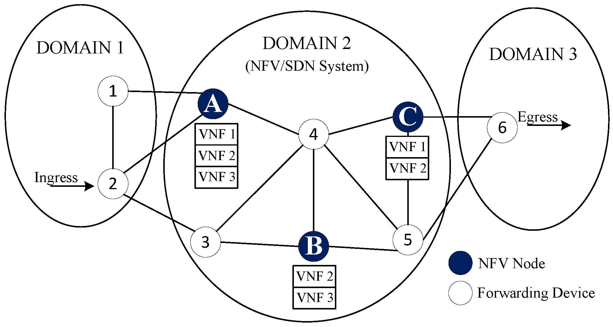
In this section, we formalize the network model used to describe an autonomous response system implemented on a cloud system and using the NFV and SDN technologies. The following system model defines three major components, namely network infrastructure (i.e., the cloud virtualized infrastructure where VNFs chains are placed), the virtual network functions and service function chains. We study an NFV/SDN system in which network functions are offered as a service. Figure 1 shows the basic network scenario for the VNF placement. It mainly consists of forwarding network devices (i.e., programmable switches or IP routers) and NFV-compliant nodes that can host a number of VNFs according to their assigned resources.
In the presented model, several VNFs can run on the same NFV node through isolated containers or virtual machines (e.g., three specific VNFs on Node A). Due to the limitations of assigned resources in NFV nodes, different instances of one VNF may be distributed between two or more NFV nodes (e.g., instances of VNF 2 are placed in Nodes A, B and C). On the other hand, SDN-based controllers can manage traffic among placed virtual functions according to requested resources in the SFCs (i.e., maximum delay, capacity, etc).
3.1. Network Infrastructure
In this work, we have modeled the network topology as a connected directed graph . Let N and E denote the sets of nodes and links, respectively, in the existing infrastructure. The aforementioned network elements have limited resources to support the requirements of a certain number of SFCs. For the resources on nodes, we just use the CPU to represent the overall resource capacity. However, this approach can be easily extended to take into account several types of resources (such as memory, disk, etc.). We represent the CPU capacity of each network node as . Moreover, we extend the model adding the delay associated with each network link , represented as . Additionally, we have defined different network domains in our model, as is shown in Figure 1.
3.2. Virtual Network Functions
Virtual network functions refer to the virtualized network entities (e.g., firewall, load balancer, etc.) that may be instantiated by the operator on top of a cloud infrastructure. In this model, the set of available VNFs is denoted as F. For each VNF , the maximum number of instances is , due to the number of licenses that the operator owns for the VNF.
On the other hand, VNFs can be implemented in containers or virtual machines running over the network infrastructure. In such a case, they would require a certain amount of resources according to the requirements of traffic demands involving them. Additionally, we have denoted as the processing delay associated with a network function .
3.3. Service Function Chains
A service function chain is composed by the sequence of VNFs that a given service needs to traverse. In this model, we denote as Q the set of incoming SFCs, as well as we formalize each SFC using the context-free language described in [9].
Following this specification, each service chain provides its ingress and egress node, denoted as and , respectively. Additionally, the order of requested VNFs between both endpoints is also specified, being the subset of VNFs requested for this SFC q. In the same way, they contain the required CPU capacity (denoted as ) for each requested VNF. Moreover, the maximum admissible end-to-end delay between the ingress and egress points, denoted as , is also included. In Table 1, we show a basic example of the described SFC.
On the other hand, we have denoted as the set of virtual links that interconnect the requested VNFs and the ingress and egress points of SFC q.
4. Problem Formulation
In this section, we formalize the network function placement and chaining problem as an ILP model. In this context, the model aims at a strategic deployment of VNFs to efficiently use the physical resources. Simultaneously, it also tries to minimize the number of physical links used between deployed VNFs, decreasing in this way the associated network costs.
4.1. ILP Model (Exact Approach)
We start introducing the decision variables and the objective function, followed by the set of constraints.
4.1.1. Variables of the Model
4.1.2. Objective Function
The objective function presents a general formulation that jointly optimizes the placement of the network functions and virtual links in the network. The first term of this function seeks to reduce the number of instances placed across the network, while the second term is intended to map the virtual links decreasing the delay among deployed VNFs.
To avoid the dominant effect in Equation (1), the possible values of the different terms are normalized into the interval (0, 1) using the function.
4.1.3. Demand Satisfaction Constraints
The constraints in (2) ensure that all SFC demands, and its requested network functions, are mapped to the given network infrastructure.
The constraints in (3) ensure that, if a network function being requested by an SFC is assigned to a node n, then at least one instance of the requested network function should be placed on that node.
4.1.4. Capacity Constraints
The capacity constraints guarantee that the sum of CPU capacities required by placed VNF instances does not exceed the available resources in each network node.
4.1.5. Path Creation Constraints
These equations are derived from the flow conservation constraints, and it ensures the proper building of the virtual paths between the required endpoints.
4.1.6. Latency Constraints
These constraints ensure that end-to-end latency requirements on mapped SFC requests will be met. Accordingly, Equation (6) is composed by a sum of the delays incurred by end-to-end latencies between mapped endpoints, and the second part defines the delay incurred by packet processing on virtual network functions.
4.1.7. Other Constraints
These constraints ensure that the required ingress and egress points, respectively, are mapped to devices in the requested physical locations.
4.2. Model Considerations
Although the above model computes the optimal NFV placements for a given network, it becomes challenging to solve it on large and even medium-scale topologies. This is because the NFV resource allocation problem is known to be NP-hard [7], so the consumption of resources and time complexity grow exponentially with the network size. On the other hand, the ILP model also requires being aware of the full set of expected SFC requests, which might be impractical for online planning of network resources. To overcome these challenges, in the next section, we propose an online heuristic strategy, which is more suitable for dynamic cloud-based environments.
5. Online Placement of Virtual Network Functions
In this section, we present an online algorithm to tackle the VNF placement problem. We consider a scenario with previously-allocated VNFs. Additionally, new SFC requests are incoming and need to be provisioned, while the usage of physical resources is minimized. In what follows, we explain the operation of the Topology Aware Placement of Virtual Network Functions (TAP-VNF) algorithm and analyze its computational complexity.
5.1. TAP-VNF Algorithm (Heuristic Approach)
We have designed an online heuristic scheme, which finds the placement of the VNFs, chaining them together in order to reduce the overall amount of resources used in the network. For such a purpose, we have observed that efficient algorithms for solving the bin packing problem are especially suitable for approaching the online VNF placement problem in SDN/NFV environments [13]. Giving a set of items (i.e., requested VNF instances) to be inserted into the bins (i.e., set of NFV nodes in the network), algorithms based on fit strategies such as FIRSTFIT, BESTFIT and WORSTFIT process an item at a time in arbitrary order and attempt to place the item in a bin according to a certain strategy. If no bin is found, they open a new bin and put the item in it.
Specifically, in this work, we leverage the suitability of the WORSTFIT algorithm for the problem described in Section 4 to develop the TAP-VNF algorithm. This algorithm takes into consideration the limited resources of the underlying network infrastructure and requirements of the requested SFCs. Therefore, it efficiently allocates the requested VNF instances while attempting to minimize server and link costs. The pseudocode of the proposed VNF placement strategy for online scenarios is shown in Algorithm 1.
| Algorithm 1 TAP-VNF algorithm. |
| Require: G, q, and , P, A Ensure: placement and chaining of requested VNFs in q
|
More in detail, the TAP-VNF algorithm requires as inputs the network topology G and the requested SFC q along with its ingress and egress nodes in the network. Additionally, the list of paths between ingress and egress nodes (sorted in increasing order of delay) P and the set of previously allocated VNFs on each node A are passed to the algorithm. Note that the size of the set P can be limited by a maximum number of paths k, which may be required in network topologies with major path redundancy. In particular, upon a new SFC being requested, Algorithm 1 starts evaluating the shortest path between the ingress and egress nodes of SFC q. Firstly, the algorithm determines if the considered path p is suitable for allocating the incoming SFC q. To do so, TAP-VNF checks that the total remaining capacity of the considered path p is enough to place all the required functions and the length of the considered path is no larger than the maximum admissible delay. In this way, end-to-end latency requirements are satisfied by the algorithm.
The main loop of the algorithm determines for the considered path the placement and chaining solutions provided by the MOD_WORSTFIT function (i.e., a modified version of the WORSTFIT scheme). If the considered path allows a feasible solution, it is returned, and the algorithm ends without further iterations. On the other hand, if no solution can be found using the current path, the algorithm iterates, and the next shortest path is then analyzed.
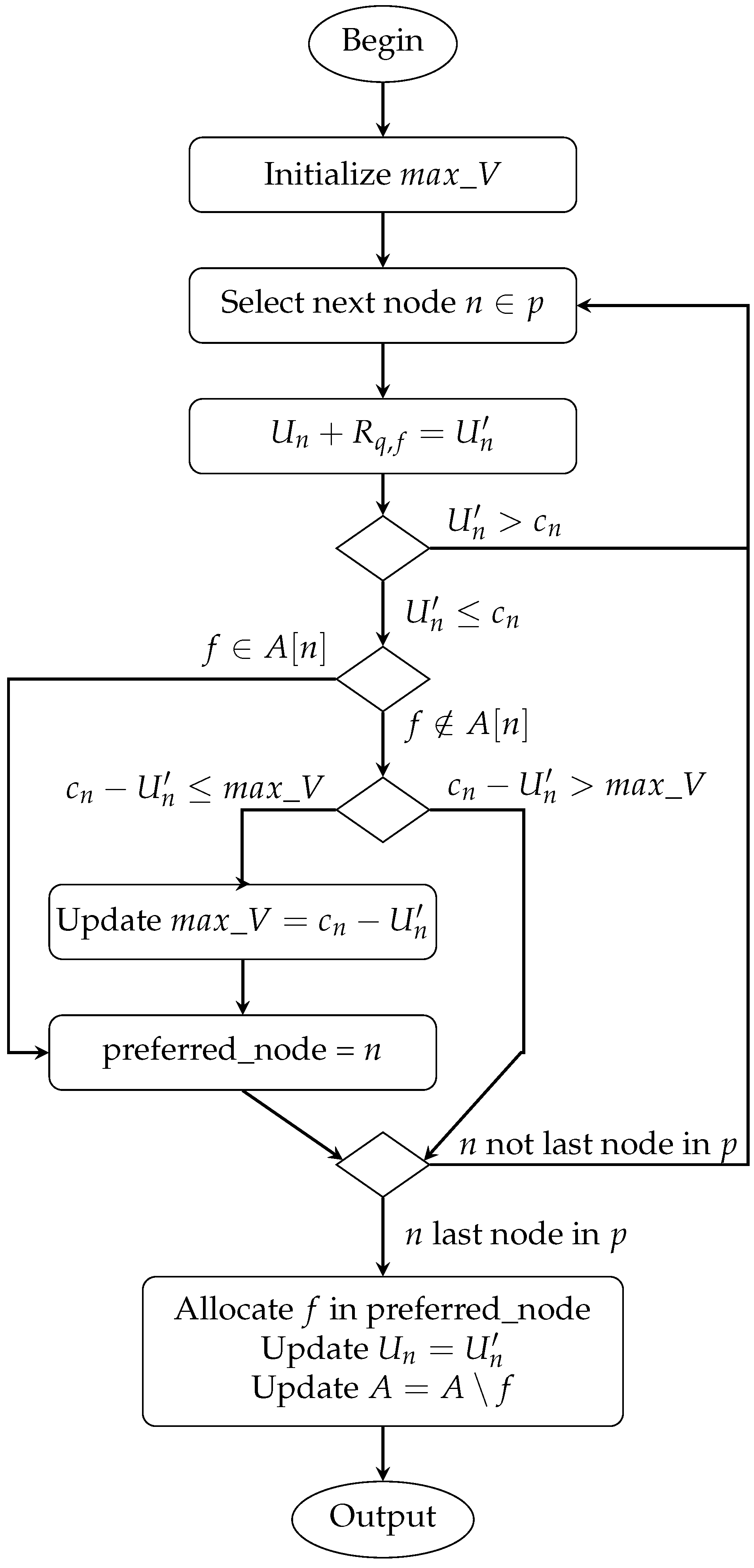
Figure 2 presents the sequence of actions of the modified MOD_WORSTFIT strategy in a flowchart for each function f requested by the incoming SFC q. This procedure evaluates each intermediate node n along the path p (i.e., except the ingress and egress nodes) as a possible candidate to allocate the considered function and computes the tentative node utilization (i.e., ) as a result of the allocation of the function f with demanded resources. In particular, after confirming that a node n has enough available CPU resources to allocate the required function, it checks if this function has been already allocated in n. In affirmative case (i.e., some instances of f exists in n), unlike the traditional WORSTFIT strategy, the same node is used again to place this function. Otherwise, the available CPU resources in n after the considered allocation of f (i.e., ) are compared with the maximum remaining resources achieved so far (i.e., ). If a new maximum is found, the considered n becomes the preferred node. Then, after considering all nodes, the one holding this condition is used to place the function. Additionally, the set of already allocated functions and node utilization is updated.
5.2. TAP-VNF Operation Example
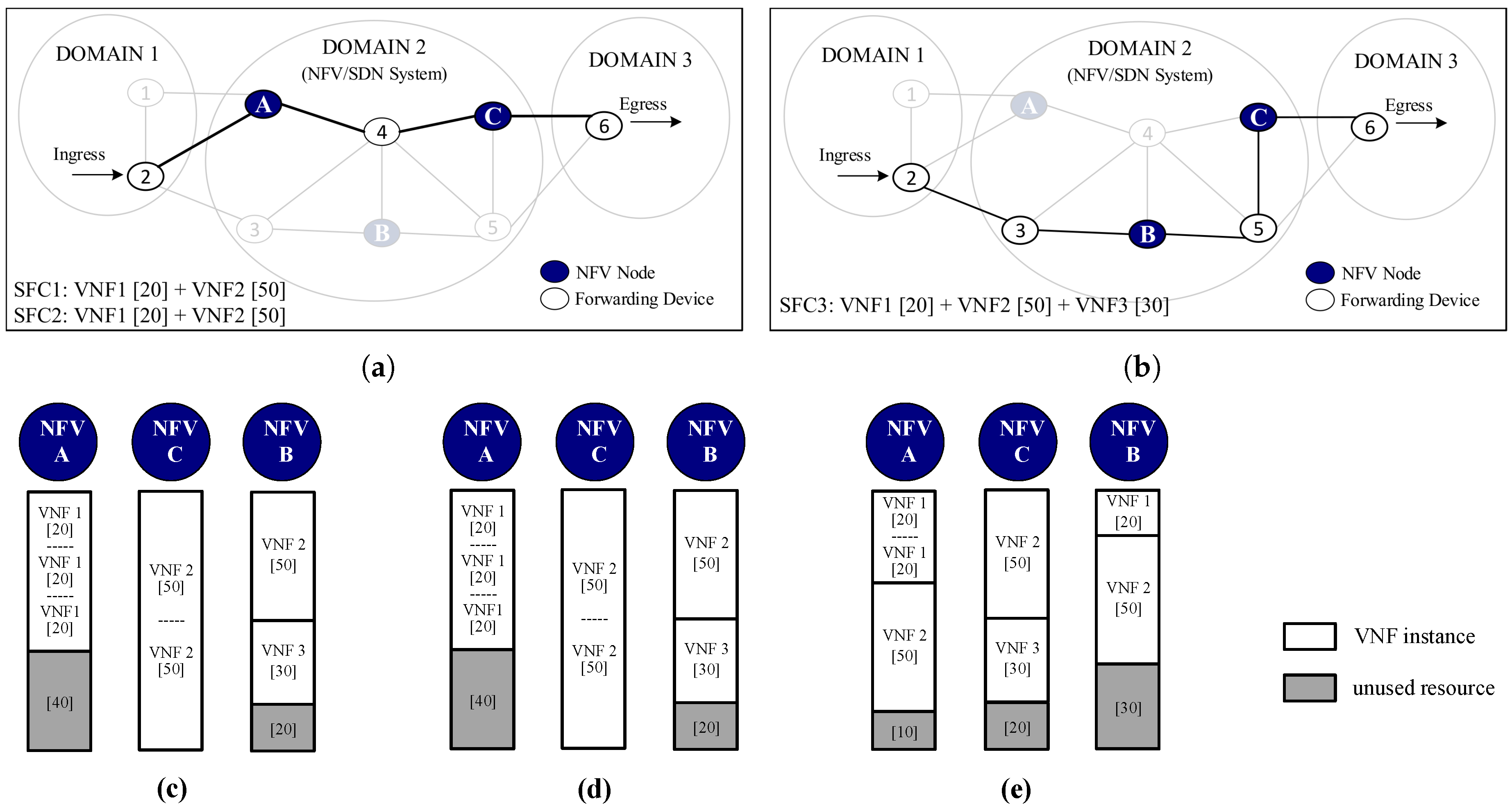
To clearly illustrate the aforementioned procedure, we have used Figure 3 to show a basic operation example of the TAP-VNF algorithm. As a complement, in this figure, we have also highlighted the differences compared with the conventional WORSTFIT method and the ILP model.
In Figure 3a,b, we show a sample network topology with 6 forwarding devices, 3 NFV-enabled nodes and 14 links, which have the same unitary delay. For simplicity, we have assumed that each NFV node has a resource capacity of 100 units. Additionally, for this example, three SFC demands were synthetically generated, which go from the ingress Node 2 in Domain 1 to the egress Node 6 in Domain 3. These demands can request up to three VNF instances with a different number of resource capacities.
As was previously discussed, the TAP-VNF algorithm starts by selecting the shortest path between ingress and egress nodes and allocates the requested VNFs across the NFV nodes. Figure 3a shows the shortest path selected by the TAP-VNF algorithm. After deploying the SFC1 and SFC2 in the network, this path is saturated. Thus, a new path with available resources and no longer than the end-to-end latency requirement is selected by the algorithm, as shown in Figure 3b. Although traditional bin packing schemes like WORSTFIT might use the same network paths to allocate the resources, they use a different number of requested VNF instances.
In Figure 3c–e, for the sake of comparison, we show the achieved results after applying the presented solutions to deploy the requested SFC demands. As can be seen in Figure 3c,d, the ILP model and the TAP-VNF algorithm achieve the same number of deployed instances (i.e., four out of seven requested VNFs). However, it is important to emphasize that these results only occur for lower values of SFC demands, as for a higher number of requests, the gap between both solutions increases. This is expected due to the fact that the ILP model is aware of the full set of demands, while the TAP-VNF algorithm allocates the requested VNFs in a one-by-one approach. More importantly, these results outperform the WORSTFIT approach in Figure 3d, which needs to deploy six VNF instances in order to satisfy the requested SFCs. This mainly happens because our MOD_WORSTFIT tries to scale up the already deployed VNF instances in order to reduce operational costs. By contrast, traditional WORSTFIT seeks to spread the requested VNFs deploying them into the NFV node with more remaining resources.
5.3. Complexity Analysis
Despite the fact that this heuristic approach does not provide optimal solutions, it outperforms the exact approach in computation time. Next, we derive the complexity of the proposed TAP-VNF algorithm. The overall complexity of Algorithm 1 is mainly determined by the for loop in lines 2–10 and the MOD_WORSTFIT function.
Although this algorithm attempts to use the first admissible path (i.e., the one satisfying capacity and delay requirements), to provide the placement and chaining solution, in the worst case, this for loop iterates k times over the sorted list of paths between the ingress and egress nodes. During each iteration, it applies the MOD_WORSTFIT scheme times in order to place each VNF instance of the requested SFC q. This is done to select the node where the requested VNF is going to be instantiated. In this work, an efficient implementation of the WORSTFIT algorithm is used to compute the placements. The code uses complex data structures to lower the running times to ), where is the maximum number of nodes in a path p. Please note that modifications to the WORSTFIT approach do not include any loop structure; therefore, the low-complexity property of this bin packing algorithm is preserved. As a result, the overall worst-case complexity of the proposed TAP-VNF algorithm is ). This online heuristic approach could be implemented in high-performance NFV/SDN servers and be executed in a real-time fashion for ARNs.
6. Evaluation Metrics
Currently, there is not a common evaluation model to assess different VNF placement strategies [9]. Therefore, we now introduce two metrics toward the evaluation of VNF placements, taking into consideration the parameters of the network infrastructure and the characteristics of requested SFCs.
6.1. Consolidation
The consolidation metric represents the fraction of deployed VNF instances over the total sum of VNFs requested by the overall set of SFC demands. In order to compute the consolidation parameter, we have derived Equation (9), which takes into account the number of placed VNF instances on the network infrastructure over the sum of all requested VNF instances in the full set of demands.
6.2. Aggregation
The aggregation metric represents the fraction of physical links used to host the virtual links required by all SFC requests, over the full set of requested virtual links. In order to compute this parameter, we include the binary variable , which takes a value of one when the physical link is used.
Equation (10) also provides a notion of how closely placed the VNFs instances are in the network infrastructure. Therefore, lower values of this ratio mean that network costs are also minimized.
7. Simulation Setup
We have carried out extensive simulations in order to assess the performance of the TAP-VNF algorithm. The considered parameters in our environment setup are described in the following section.
All experimental simulations were performed on the network graph Abilene (11 nodes, 28 links), taken from the SNDlib dataset [14]. The selected topology represents a typical topology of Internet and ISP networks. The delay on each link is assumed as the propagation latency calculated from the geographical distances among nodes in the topology. For all experimental simulations, we have used a fixed amount of 100 CPU units for each node of the considered topology. As in [15], we have assumed that all nodes in the topology can be used to deploy VNFs. In these simulations, we have used five types of VNFs (i.e., VNF1, VNF2, VNF3, VNF4 and VNF5) requiring fixed or variable (random) CPU units. The resource requirements are given in Table 2.
To properly assess the performance of the proposed solution, we have carefully designed four evaluation profiles using sets of SFC requests with different parameters. A summary of considered profiles is shown in Table 3. The SFC demands were generated with a random number of VNFs (i.e., from 2 to 5) and ingress/egress endpoints. The selection of these nodes was ensured to be at least two hops away. These evaluation profiles are used to provide important insights into the performance of the TAP-VNF algorithm.
The heuristic TAP-VNF algorithm was developed using the programming language Python. Likewise, we implement the ILP model using the linear programming solver Gurobi Optimizer [16]. Additionally, each simulation instance was tested 15 times, setting different random seeds on the selected topology. All computations were performed on a Laptop equipped with a 3.30-GHz Intel Core i7 and 32 GB RAM.
8. Results and Discussion
In this section, we first give an in-depth look at the optimal results achieved by the ILP model. Afterward, we assess the proposed TAP-VNF algorithm and validate its results using the exact approach, as well as traditional bin packing strategies. The consolidation and aggregation parameters are used to discuss the performance of the different approaches. Then, we present the computation times required by each solution. Finally, the performance of TAP-VNF on several real-world topologies is discussed.
8.1. Optimal Solution Assessment
For this experimental simulation, the SFC requests were generated using the Scenario I of Table 3. In order to get all the optimal placements for each set of SFC requests, we have independently performed each simulation with an increased number of SFC requests.
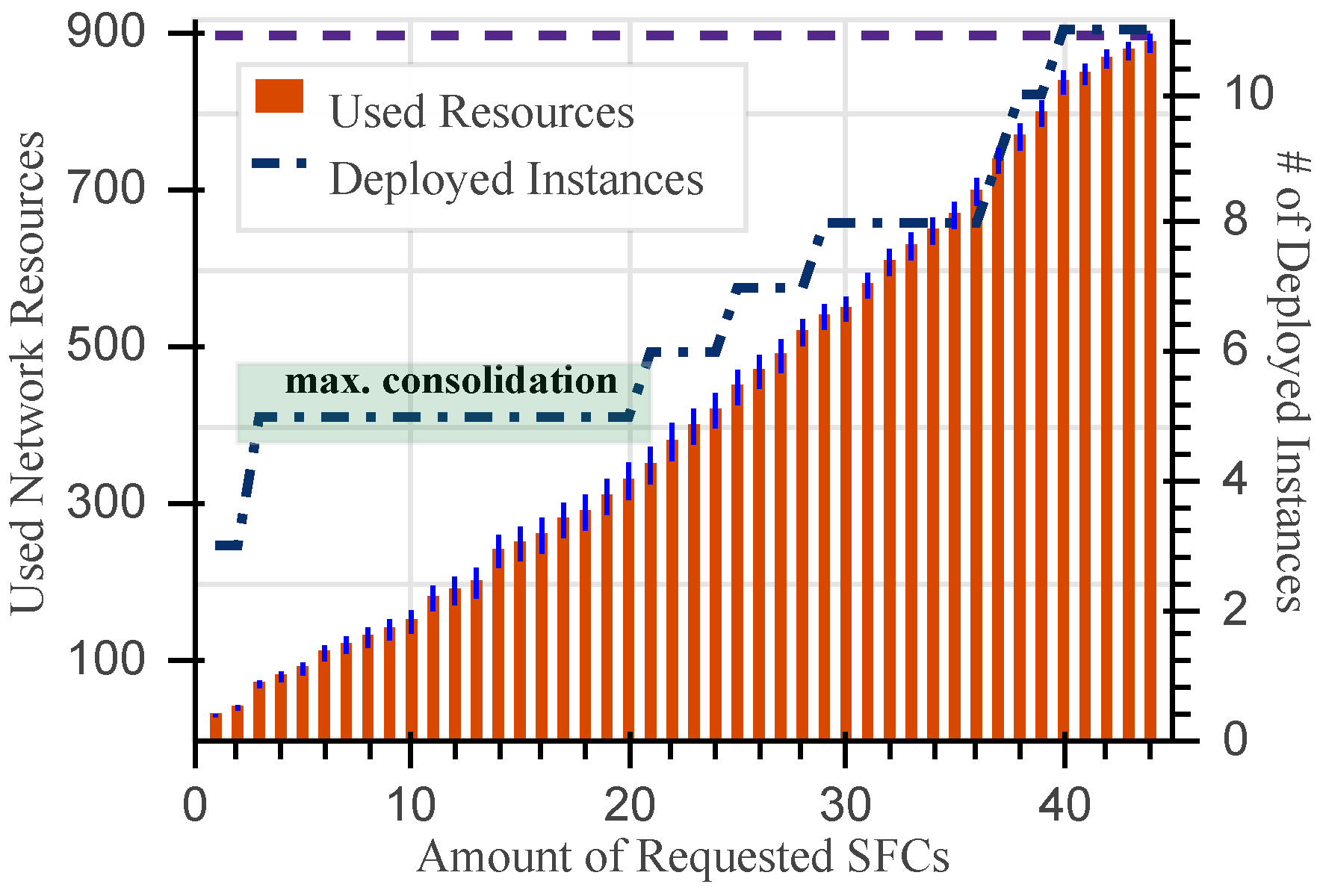
Figure 4 shows the network resources used by the ILP model together with the average number of deployed VNFs instances. The x-axis enumerates the number of requested SFCs, which are increased until the fulfillment of existing network resources. Precisely, the overall amount of available resources in the presented topology is emphasized in the figure with the dashed line at the top (i.e., ).
It can be seen that the exact approach accomplishes all the placements using 11 VNF instances. As expected, when the number of resources requested by SFCs increases, the number of deployed VNFs also grows. More interesting is the behavior shown in the interval denoted in the figure as max. consolidation, where the number of deployed VNFs instances is not influenced by the increase of requested resources. Specifically, although an additional 260 CPU units are requested by 20 SFCs with respect to three SFCs, the average number of deployed VNF instances remains the same, at five instances. This desired behavior of the optimal placements avoids important licensing costs related to the instantiation of new VNF instances.
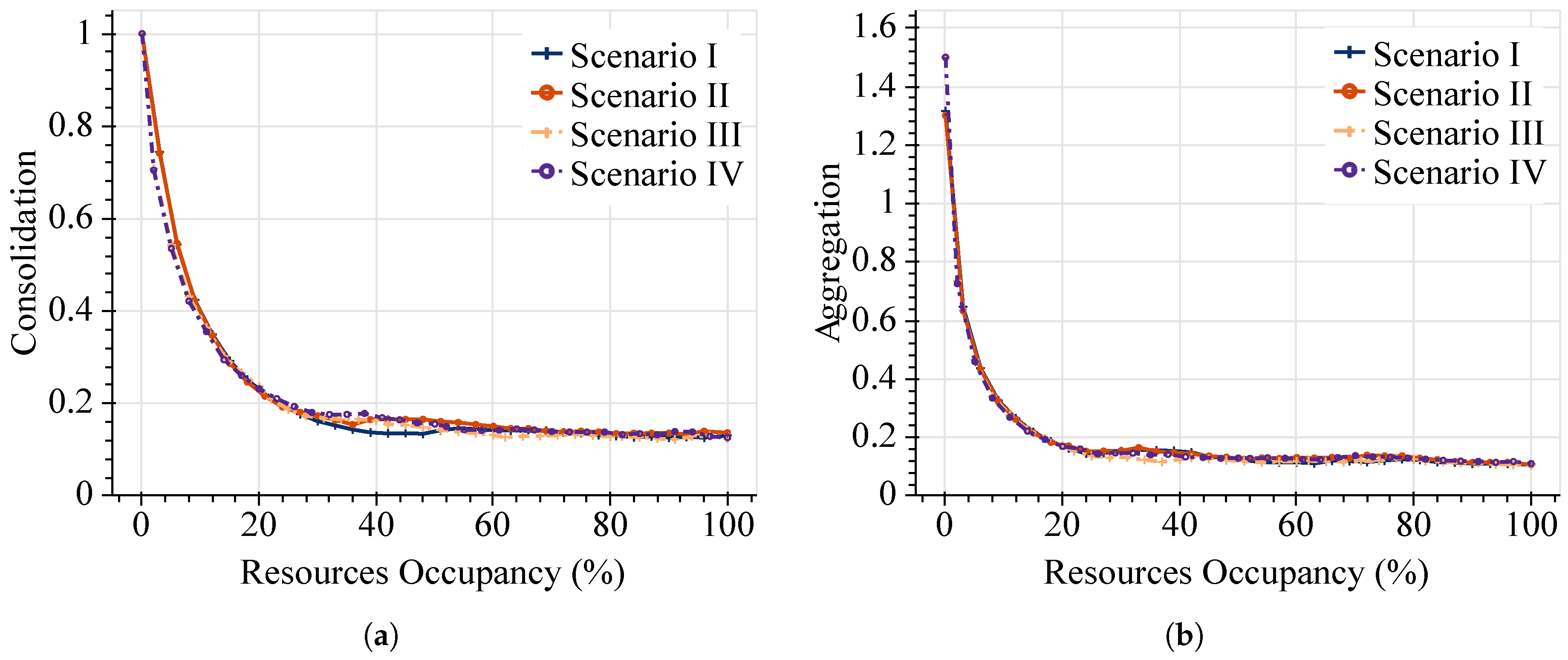
To gain insight into the ILP model performance across all the evaluation profiles in Table 3, we use the proposed evaluation metrics. Consequently, in Figure 5, we show the performance evaluation for optimal VNF placements in terms of the consolidation and aggregation ratios as functions of the resources’ occupancy efficiency. These metrics are plotted against the percentage of resources’ occupancy, which is directly related to the number of requested SFCs in each scenario.
Figure 5a shows the consolidation ratios of the exact approach. Given the nature of this metric, higher values are obtained when the amount of requested SFCs is low. However, under more demanding workloads, the consolidation effect becomes more appreciable. Specifically, this model can achieve values lower than 0.2 once 20% of the resources’ occupancy is exceeded. For the 100% of resources’ occupancy, consolidation values lower than 0.14 are achieved in the four scenarios. This means that the optimal solution only needs to instantiate 14% of the requested VNFs to satisfy all the CPU demands in SFC requests. It is worth highlighting that similar results are reached by the offline approach in all the considered evaluation profiles.
On the other hand, Figure 5b shows the attained aggregation ratios. As expected, less aggregation is also achieved when the number of incoming SFCs is low. This is because the first incoming SFC is likely to have fewer virtual links than the number of physical links required to map them from the ingress to the egress nodes across the network topology. Consequently, values higher than one are obtained at the beginning of the simulations. Similarly, aggregation ratios lower than 0.2 are achieved by the exact model irrespective of the considered parameters of SFC profiles. More in detail, in this experimental simulation, the lowest aggregation ratios achieved are around 0.1 (at 100% of resources’ occupancy). This result means that each physical link of the network infrastructure can host around 10 virtual links of the full set of deployed SFC requests. Consequently, network operators can use fewer network resources (e.g., data links and bandwidth) to interconnect their supported network services.
8.2. TAP-VNF Performance
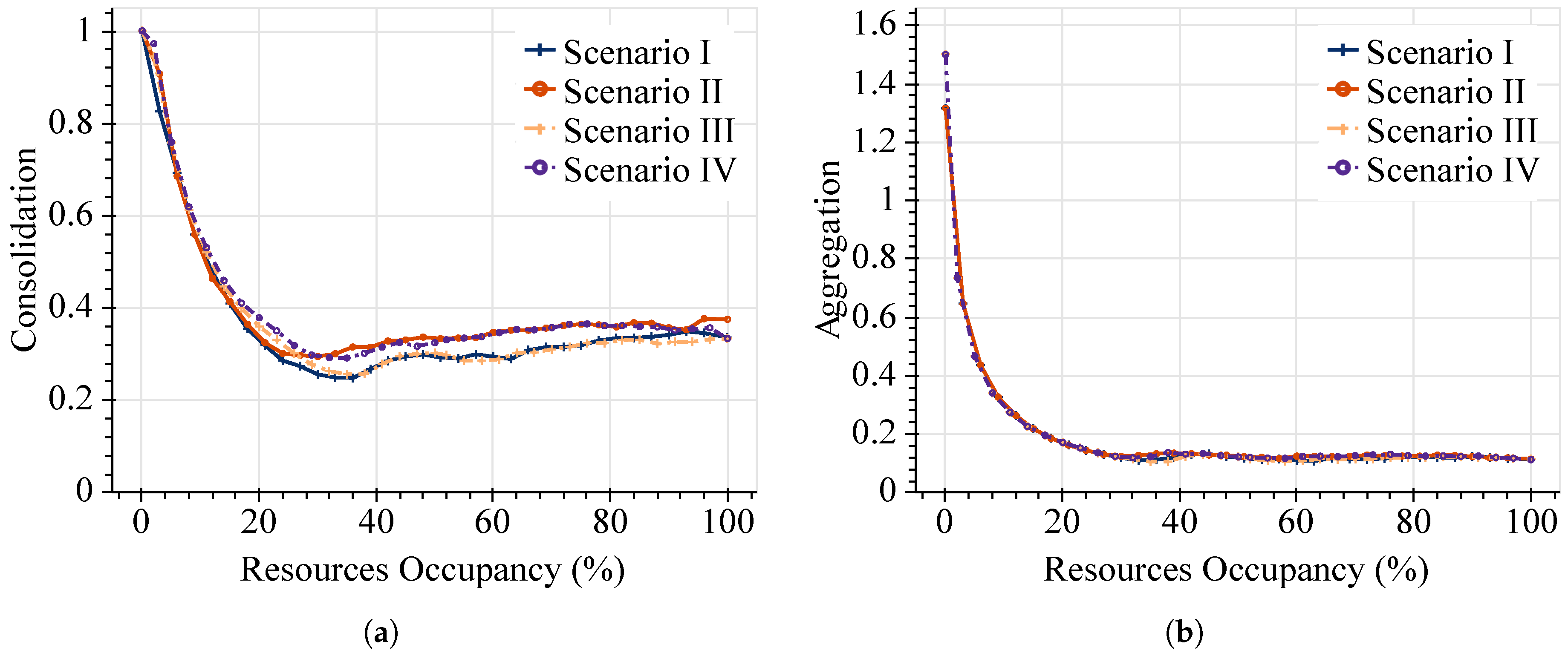
We also present the heuristic algorithm results for the consolidation and aggregation metrics using the same network topology and SFC profiles. The TAP-VNF algorithm exploits the key idea behind the consolidation parameter. Therefore, it tries to scale up the already deployed VNF instances in order to reduce operational costs. Figure 6 shows the performance evaluation after running the TAP-VNF algorithm on the Abilene topology.
As can be seen in Figure 6a, the consolidation values of the online approach present the same pattern as in the offline model, which corroborates that our proposed algorithm preserves the desired properties. In this case, consolidation ratios under 0.4 are accomplished once the resources’ occupancy exceeds 20%.
On the other hand, aggregation ratios in Figure 6b illustrate almost an identical behavior compared to the offline approach in terms of mapping virtual links over the physical infrastructure. In spite of the high aggregation values at the beginning of requested SFCs, the more resources are required, the better are the aggregation ratios achieved by this online approach. This figure confirms that the TAP-VNF algorithm can aggregate more as the number of requested SFCs increases. For instance, at 100% of resource utilization, the online algorithm achieves a minimum ratio of aggregation of 0.11, which represents less than 8% of the difference compared to the optimal values for the same conditions. As in the previous cases, similar results are achieved in the four considered scenarios. This result validates the adequate performance of the proposed solution for VNF placements in online scenarios.
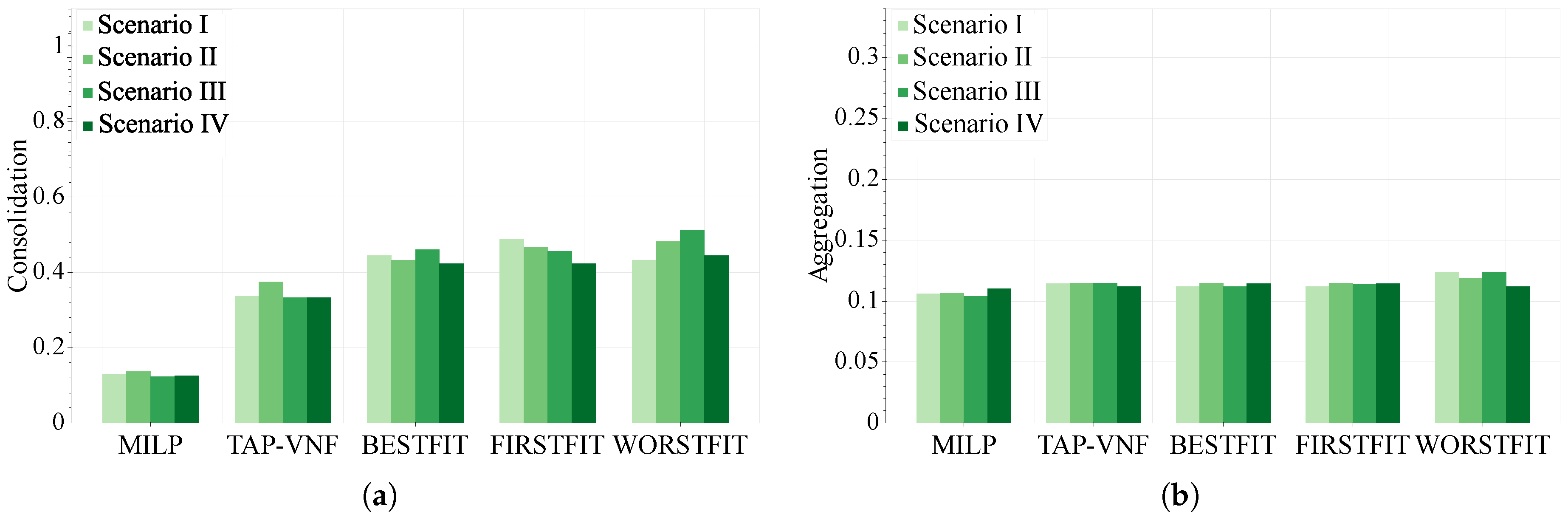
In order to further evaluate the effectiveness of the proposed algorithm, Figure 7 shows its performance against the ILP model using both metrics when network resources are 100% used. Additionally, we also include three traditional bin packing schemes, namely BESTFIT, FIRSTFIT and WORSTFIT. Specifically, these strategies are applied in the procedure described by the pseudocode of Algorithm 1 to provide the placement and chaining solutions instead of the MOD_WORSTFIT (Line 5).
In this figure, we can appreciate that close-to-optimal values are reached by the TAP-VNF algorithm. Although smaller optimality gaps are observed for the aggregation metric, the proposed online approach attains acceptable consolidation ratios. Moreover, in Figure 7a, the proposed online algorithm clearly outperforms the traditional bin packing strategies in terms of consolidation ratios. This result is due to the fact that the MOD_WORSTFIT function allocates requested VNFs, prioritizing nodes where instances of these functions are already placed. In terms of aggregation ratios, similar results are achieved by all the evaluated approaches in Figure 7b. In this case, slightly better values can be reached by the BESTFIT and FIRSTFIT strategies, compared with the TAP-VNF approach. This result is expected due to the characteristics of these bin packing algorithms. While the first two strategies allocate as many requested VNFs as possible over the same node (i.e., without requiring any physical link), the WORSTFIT attempts to place different requested VNFs on different nodes, resulting in more physical links used.
8.3. Execution Time
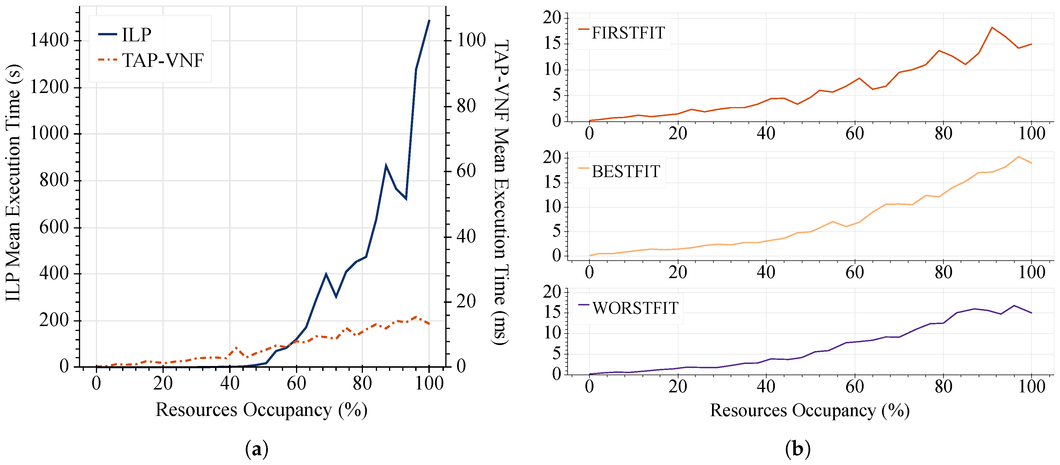
Another important aspect to discuss is the execution time required by the presented solutions. To do so, in Figure 8, we show the average running time of the different placement strategies. For this evaluation, the requested SFCs were created following the parameters defined by Scenario I in the previous Table 3. Similarly, we have used the Abilene topology due to the high running times of the ILP model.
It is worth highlighting that, in Figure 8a, the TAP-VNF algorithm and the ILP model differ drastically in terms of computing time. Although the proposed strategy outperforms in all cases the optimal model, a higher improvement is achieved as the resources’ occupancy grows. For instance, when the resource occupancy exceeds 50%, the processing time required by the optimal model increases dramatically, which is a great limitation for current networking environments. In essence, the TAP-VNF algorithm accomplishes good consolidation and aggregation ratios extremely quickly (less than 15 ms), while the ILP model can take up to 25 min to find a solution, leading to a fifth order of magnitude improvement. As far as scalability is concerned, the execution times indicate that TAP-VNF is more scalable, a characteristic that is crucial in practical applications. These considerations suggest that it would be reasonable to use TAP-VNF for dynamic resource allocation in cloud-based autonomous response networks. On the other hand, Figure 8b corroborates that the TAP-VNF algorithm is of similar complexity as the traditional bin packing schemes.
8.4. Analysis of More Topologies
To properly understand the behavior of the presented placement strategies, we also expand our performance analysis across several network topologies of SNDlib [14]. This online available dataset has been extensively used to test the performance of novel algorithms and protocols in SDN/NFV research. Furthermore, it contains different classes of network graphs (i.e., regional, continental and global) with a diverse range of network sizes (i.e., from 10–161 nodes). Thus, it enables us to shed light on the performance of the proposed TAP-VNF algorithm in terms of the presented evaluation metrics across a wide range of network topologies.
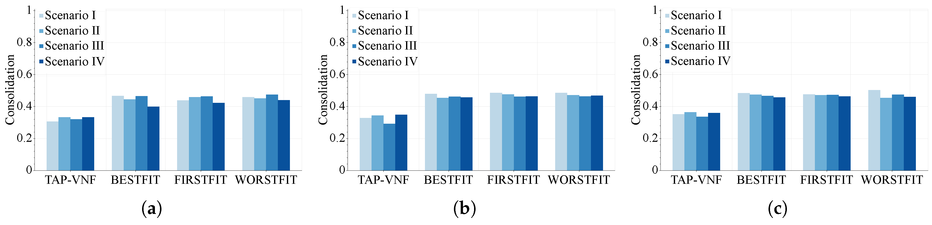
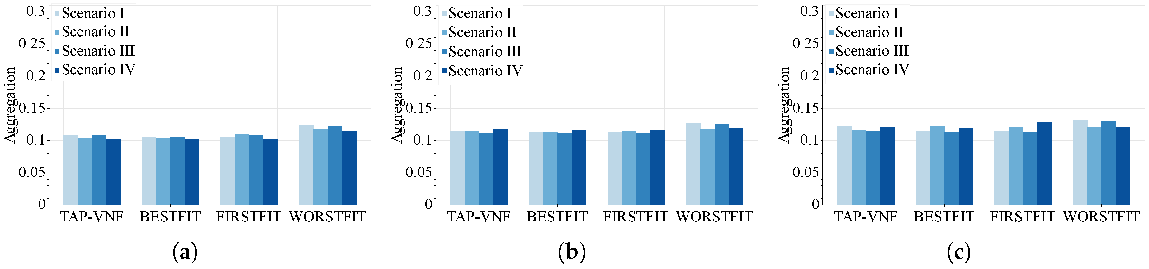
In Figure 9 and Figure 10, we show the consolidation and aggregation ratios of the proposed placement strategies in different network topologies, respectively. For these evaluations, we have considered three topologies representative of different network scales and connectivity degrees, namely Atlanta (15 nodes, 44 links), Janos_US (26 nodes, 84 links) and Pioro (40 nodes, 89 links). In the last case, we limit the maximum amount of considered paths to . The consolidation and aggregation ratios were measured at 100% of used resources and presented as a function of the SFC profiles for different allocation strategies.
Figure 9 shows the consolidation ratios of the TAP-VNF algorithm, while it attempts to allocate the requested VNF instances over the described topologies. The requested SFCs were generated according to all scenarios in Table 3. It can be seen that similar consolidation values are accomplished for each proposed scenario across network topologies with different network sizes and connectivity degrees. This behavior reveals that the consolidation of the proposed TAP-VNF algorithm is irrespective of the network topology. Undoubtedly, this result is promising because it enables network operators to design placement strategies that consolidate more requested VNF instances without significant variations regarding different network topologies.
On the other hand, Figure 10 shows the aggregation accomplished by the online placement approach (i.e., the TAP-VNF algorithm) for the same three network topologies. Similar to the consolidation metric, the aggregation of proposed placement strategies is not strongly influenced by the considered topologies. For this reason, it may also be corroborated that the proposed TAP-VNF algorithm is not dependent on the network topology. This behavior is critical for resource allocation in cloud-based environments where the network infrastructure can be dynamically generated to ensure the requirements of the supported network applications.
9. Conclusions
In this paper, we have tackled the VNF placement problem for autonomous response networks. This problem is investigated through different approaches. First, we have presented a generic model able to find the optimal VNF placement for offline scenarios. Then, to address dynamic scenarios, we have proposed a heuristic algorithm that is based on efficient solutions of the bin packing problem. To evaluate the performance of the presented solutions, we have also identified two metrics in order to assess the resource occupancy efficiency of the proposed methods. Experimental simulations show that the heuristic approach achieves near-optimal solutions with smaller optimality gaps for the aggregation metric (with differences under 8%). Moreover, the obtained results validate that the proposed online algorithm outperforms the traditional bin packing strategies (i.e., BESTFIT, FIRSTFIT and WORSTFIT) in terms of consolidation ratios, being a more suitable solution for the VNF placement problem. Additionally, significantly smaller computation times (compared to the ILP model) are required by the TAP-VNF algorithm. Therefore, using the proposed placement strategy, network operators can improve the efficiency of resource allocation in cloud-based environments. As future work, we would like to extend the proposed TAP-VNF algorithm considering techniques based on the machine learning approach.
Author Contributions
All the authors contributed equally to the work. All authors read and approved the final manuscript.
Acknowledgments
This work was supported by the Ministerio de Economía y Competitividad of the Spanish Government under Project TEC2016-76795-C6-1-R and AEI/FEDER, UE. The authors would like to thank Ralph Koning from SNE for insightful discussions at earlier versions of this manuscript.
Conflicts of Interest
The authors declare no conflict of interest.
Abbreviations
The following abbreviations are used in this manuscript:
| 5G | 5th Generation Wireless Systems |
| ANM | Autonomic Network Management |
| ARN | Autonomous Response Networks |
| CAPEX | Capital Expenditures |
| CPU | Central Processing Unit |
| GNFC | Greedy Network Function Consolidation |
| IP | Internet Protocol |
| ILP | Integer Linear Programming |
| NFC | Network Function Consolidation |
| NFV | Network Function Virtualization |
| OPEX | Operational Expenditures |
| SARNET | Secure Autonomous Response Networks |
| SDN | Software Defined Networks |
| SFC | Service Function Chain |
| TAP-VNF | Topology Aware Placement of Virtual Network Functions |
| VM | Virtual Machine |
| VNF | Virtual Network Function |
References
- Garay, J.; Matias, J.; Unzilla, J.; Jacob, E. Service Description in the NFV Revolution: Trends, Challenges and a Way Forward. IEEE Commun. Mag. 2016, 54, 68–74. [Google Scholar] [CrossRef]
- Kreutz, D.; Ramos, F.M.V.; Veríssimo, P.E.; Rothenberg, C.E.; Azodolmolky, S.; Uhlig, S. Software-Defined Networking: A Comprehensive Survey. Proc. IEEE 2015, 103, 14–76. [Google Scholar] [CrossRef]
- Movahedi, Z.; Ayari, M.; Langar, R.; Pujolle, G. A Survey of Autonomic Network Architectures and Evaluation Criteria. IEEE Commun. Surv. Tutor. 2012, 14, 464–490. [Google Scholar] [CrossRef]
- Huebscher, M.C.; McCann, J.A. A Survey of Autonomic Computing–Degrees, Models, and Applications. ACM Comput. Surv. 2008, 40, 1–28. [Google Scholar] [CrossRef]
- Koning, R.; Graaff, B.D.; Meijer, R.; Laat, C.D.; Grosso, P. Measuring the Effectiveness of SDN Mitigations Against Cyber Attacks. In Proceedings of the 3rd IEEE Conference on Network Softwarization (NetSoft), Bologna, Italy, 3–7 July 2017; pp. 1–6. [Google Scholar]
- SARNET Project—SNE Research Group, University of Amsterdam. Available online: https://sarnet.uvalight.net/ (accessed on 30 March 2018).
- Herrera, J.G.; Botero, J.F. Resource Allocation in NFV: A Comprehensive Survey. IEEE Trans. Netw. Serv. Manag. 2016, 13, 518–532. [Google Scholar] [CrossRef]
- Bhamare, D.; Jain, R.; Samaka, M.; Erbad, A. A Survey on Service Sunction Chaining. J. Netw. Comput. Appl. 2016, 75, 138–155. [Google Scholar] [CrossRef]
- Mehraghdam, S.; Keller, M.; Karl, H. Specifying and Placing Chains of Virtual Network Functions. In Proceedings of the 3rd IEEE International Conference on Cloud Networking (CloudNet), Luxembourg, 8–10 October 2014; pp. 7–13. [Google Scholar]
- Luizelli, M.C.; Bays, L.R.; Buriol, L.S.; Barcellos, M.P.; Gaspary, L.P. Piecing together the NFV provisioning puzzle: Efficient placement and chaining of virtual network functions. In Proceedings of the IFIP/IEEE International Symposium on Integrated Network Management (IM), Ottawa, ON, Canada, 11–15 May 2015; pp. 98–106. [Google Scholar]
- Wen, T.; Yu, H.; Sun, G.; Liu, L. Network Function Consolidation in Service Function Chaining Orchestration. In Proceedings of the IEEE International Conference on Communications (ICC), Kuala Lumpur, Malaysia, 22–27 May 2016; pp. 1–6. [Google Scholar]
- Li, X.; Wu, J.; Tang, S.; Lu, S. Let’s Stay Together: Towards Traffic Aware Virtual Machine Placement in Data Centers. In Proceedings of the 33rd IEEE Conference on Computer Communications (INFOCOM), Toronto, ON, Canada, 27 April–2 May 2014; pp. 1842–1850. [Google Scholar]
- Hsieh, C.H.; Chang, J.W.; Chen, C.; Lu, S.H. Network-Aware Service Function Chaining Placement in a Data Center. In Proceedings of the 18th Network Operations and Management Symposium (APNOMS), Kanazawa, Japan, 5–7 October 2016. [Google Scholar]
- Orlowski, S.; Pióro, M.; Tomaszewski, A.; Wessäly, R. SNDlib 1.0-Survivable Network Design Library. Networks 2010, 55, 276–286. [Google Scholar] [CrossRef]
- Wang, L.; Lu, Z.; Wen, X.; Knopp, R.; Gupta, R. Joint Optimization of Service Function Chaining and Resource Allocation in Network Function Virtualization. IEEE Access 2016, 4, 8084–8094. [Google Scholar] [CrossRef]
- Gurobi Optimizer (Version 7.5). Available online: http://www.gurobi.com/ (accessed on 30 March 2018).
Figure 1.
Basic network scenario in VNF placements.

Figure 2.
Flowchart of the MOD_WORSTFIT scheme.

Figure 3.
Basic operation example of the TAP-VNF algorithm. (a) Shortest path selected by TAP-VNF; (b) suitable path selected by TAP-VNF; (c) exact approach (ILP model); (d) TAP-VNF algorithm (MOD_WORSTFIT); and (e) bin packing algorithm (WORSTFIT).
Figure 3.
Basic operation example of the TAP-VNF algorithm. (a) Shortest path selected by TAP-VNF; (b) suitable path selected by TAP-VNF; (c) exact approach (ILP model); (d) TAP-VNF algorithm (MOD_WORSTFIT); and (e) bin packing algorithm (WORSTFIT).

Figure 4.
Optimal resource allocation for the ILP method.

Figure 5.
Performance evaluation of the ILP model in the Abilene topology. (a) Optimal consolidation of requested VNF instances; (b) optimal aggregation of requested virtual links.
Figure 5.
Performance evaluation of the ILP model in the Abilene topology. (a) Optimal consolidation of requested VNF instances; (b) optimal aggregation of requested virtual links.

Figure 6.
Performance evaluation of the online NFV placement strategy. (a) Heuristic consolidation of requested VNF instances; and (b) heuristic aggregation of requested virtual links.
Figure 6.
Performance evaluation of the online NFV placement strategy. (a) Heuristic consolidation of requested VNF instances; and (b) heuristic aggregation of requested virtual links.

Figure 7.
Performance comparison between optimal and heuristic solutions. (a) Consolidation metric; and (b) aggregation metric.
Figure 7.
Performance comparison between optimal and heuristic solutions. (a) Consolidation metric; and (b) aggregation metric.

Figure 8.
Execution time performance across the proposed placement strategies. (a) ILP vs. TAP-VNF solutions; and (b) bin packing schemes.
Figure 8.
Execution time performance across the proposed placement strategies. (a) ILP vs. TAP-VNF solutions; and (b) bin packing schemes.

Figure 9.
Consolidation of placement strategies across topologies of the SNDlib dataset. (a) Atlanta; (b) Janos_US; and (c) Pioro.
Figure 9.
Consolidation of placement strategies across topologies of the SNDlib dataset. (a) Atlanta; (b) Janos_US; and (c) Pioro.

Figure 10.
Aggregation of placement strategies across topologies of the SNDlib dataset. (a) Atlanta; (b) Janos_US; and (c) Pioro.
Figure 10.
Aggregation of placement strategies across topologies of the SNDlib dataset. (a) Atlanta; (b) Janos_US; and (c) Pioro.


Table 1.
Basic example of the service function chain request.
| Parameter | Value |
|---|---|
| Ingress Point | Node 2 |
| Requested VNFs | VNF1, VNF2, VNF3 |
| CPU Requirements | [10, 10, 10] (units) |
| Delay Requirement | 50 ms (end-to-end) |
| Egress Point | Node 6 |
Table 2.
Resource requirements for network functions.
| Number of VNFs | CPU Requirements (units) | |
|---|---|---|
| Fixed | Random | |
| 5 | 10 | [1, 20] |
Table 3.
Parameters of SFC profiles.
| SFC Profile | VNF Requirement | Distribution | Mean | Var |
|---|---|---|---|---|
| Scenario I | fixed | uniform | 0.2 | 0.0 |
| Scenario II | random | uniform | 0.2 | 0.0 |
| Scenario III | fixed | non-uniform | 0.2 | 0.043 |
| Scenario IV | random | non-uniform | 0.2 | 0.043 |
© 2018 by the authors. Licensee MDPI, Basel, Switzerland. This article is an open access article distributed under the terms and conditions of the Creative Commons Attribution (CC BY) license (http://creativecommons.org/licenses/by/4.0/).
Share and Cite
MDPI and ACS Style
Ochoa-Aday, L.; Cervelló-Pastor, C.; Fernández-Fernández, A.; Grosso, P. An Online Algorithm for Dynamic NFV Placement in Cloud-Based Autonomous Response Networks. Symmetry 2018, 10, 163. https://doi.org/10.3390/sym10050163
AMA Style
Ochoa-Aday L, Cervelló-Pastor C, Fernández-Fernández A, Grosso P. An Online Algorithm for Dynamic NFV Placement in Cloud-Based Autonomous Response Networks. Symmetry. 2018; 10(5):163. https://doi.org/10.3390/sym10050163
Chicago/Turabian StyleOchoa-Aday, Leonardo, Cristina Cervelló-Pastor, Adriana Fernández-Fernández, and Paola Grosso. 2018. "An Online Algorithm for Dynamic NFV Placement in Cloud-Based Autonomous Response Networks" Symmetry 10, no. 5: 163. https://doi.org/10.3390/sym10050163
Note that from the first issue of 2016, this journal uses article numbers instead of page numbers. See further details here.