Agustín de Betancourt’s Double-Acting Steam Engine: Geometric Modeling and Virtual Reconstruction


1
Department of Engineering Graphics, Design and Projects, University of Jaén, Campus de las Lagunillas, s/n, 23071 Jaén, Spain
2
University of Jaén, Campus de las Lagunillas, s/n, 23071 Jaén, Spain
3
Research Group ‘Engineering Graphics and Industrial Archaeology’, University of Jaén, Campus de las Lagunillas, s/n, 23071 Jaén, Spain
*
Author to whom correspondence should be addressed.
Symmetry 2018, 10(8), 351; https://doi.org/10.3390/sym10080351
Submission received: 16 July 2018
/
Revised: 13 August 2018
/
Accepted: 17 August 2018
/
Published: 20 August 2018
(This article belongs to the Special Issue Symmetry and Engineering Design)
Abstract
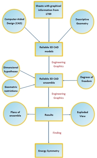
:In this paper, the geometric modeling and virtual reconstruction of the double-acting steam engine designed by Agustín de Betancourt in 1789 are shown. For this, the software Autodesk Inventor Professional is used, which has allowed us to obtain its geometric documentation. The material for the research is available on the website of the Betancourt Project of the Canary Orotava Foundation for the History of Science. Almost all parts of the steam engine are drawn on the sheets, but due to the absence of scale and space, it is insufficient to obtain an accurate and reliable 3D CAD (Computer-Aided Design) model. For this reason a graphic scale has been adopted so that the dimensions of the elements are coherent. Also, it has been necessary to make some dimensional and geometric hypotheses, as well as restrictions of movement (degrees of freedom). Geometric modeling has made it possible to know that the system is balanced with the geometric center of the rocker arm shaft, and presents an energetic symmetry whose axis is the support of the parallelogram where the shaft rests: calorific energy to the left and mechanical energy to the right, with the rocker arm acting as a transforming element from one to the other.
1. Introduction
The research carried out has been developed within a research project of excellence about the figure of Agustín de Betancourt [1,2,3], studying and analyzing his best-known historical inventions, both in terms of geometric modeling [4,5].
The main objective of this paper is to present the digital restitution obtained from a 3D CAD (computer-aided design) model as well as the geometric documentation of the developed engine, following in this way the objectives stated in the document of the Seville Principles [6] on virtual archaeology, which delves into the London Charter [7] for computer-aided visualization of cultural heritage. Similarly, the purpose of this digital restitution is based on three pillars: research, documentation and dissemination, and underlines three fundamental principles such as authenticity, historical rigor and scientific transparency.
The steam engine has been studied by various authors such as Worcester, Savery, Papin, Newcomen, and Watt for its importance in the Industrial Revolution. However, this engine has always been considered a monopoly of its authors, and therefore Betancourt, as the one responsible for the formation of the Real Gabinete de Máquinas del Palacio del Buen Retiro de Madrid (Royal Cabinet of Machines of the Buen Retiro Palace of Madrid), expanded on this invention. On the one hand, James Watt’s single-acting steam engines, which were installed by the Périer industrialists in Chaillot to facilitate the Paris water supply, were displaced by the double-acting steam engines that were kept in secret. The introduction of the condenser by James Watt tripled the performance of the Newcomen engine and in addition showed that steam expansion could be used to move the piston, decreasing the amount of water vapor used in each cycle [8]. Therefore, Betancourt decided to visit James Watt in Birmingham to explain its operation, but failed [9]. However, back in London he was able to observe one of these engines in the Albion Mills and discover the principle of its operation. Thus Betancourt wrote the memory of the double-acting steam engine, presenting it to the Paris Academy of Sciences, where he received the approval of a Commission appointed for this purpose, composed of the scientists Borda and Monge. He built a machine very similar to Watt’s, but devised an ingenious solution for the transmission of the plunger movement, similar to that of the Scottish engineer.
The steam engine is considered to be double acting since the water vapor acts on both sides of the piston, achieving a remarkable increase in efficiency and transforming the calorific energy of the water vapor into mechanical energy. The improvements introduced in the Watt machine and shared with the Betancourt machine were three: Firstly, the water vapor is not condensed in the steam cylinder but in a separate chamber cooled by air, and equipped with a vacuum pump that absorbs the water vapor from the cylinder (isolated in order to stay at the steam temperature), which removes condensed water; Secondly, the water vapor is injected into the two faces of the piston to move it in both directions, changing the reciprocating movement of the piston to rotary by means of a planetary gear system; and finally, the chain that joined the piston with the rocker arm is eliminated, replacing it with a parallelogram that governs the movement of the former.
Regarding the 3D reconstruction process, a brief review of different methodologies carried out in recent years is presented below. On the one hand, there have been numerous proposals on sketch-based modeling methods [10,11,12], and many of these proposals have been included in an extensive review by Olsen et al. [13]. There are three main approaches to sketch-based modeling [14]: gestural systems provide predefined gesture alphabets that encode some geometric modeling operations; reconstructional systems apply geometric reconstruction techniques to build the object’s geometry from a sketch, and hybrid systems combine the two previous approaches.
Similarly, freeform sweeps detection and reconstructions methods have been proposed [15], or systematic methods for the semiautomatic generation of 2.5D models from paintings, mainly to help blind people to interpret 2D drawings using bas-reliefs [16]. Other methods proposed include animated constructions of linear drawings [17], 3D reconstructions of trees based on virtual reality [18,19], and empirical techniques based on knowledge of descriptive geometry and direct measurement [4,5].
However, one of the most developed lines is the 3D reconstruction of line drawings. Extensive studies have been carried out on the state of the art of 3D reconstruction of line drawings [14,20] in which studies covering the previous 30 years were compiled, analyzing the methods and mathematical algorithms necessary to tackle 3D reconstruction. In short, the aim is to study the methods necessary to convert a two-dimensional linear drawing into a three-dimensional model that the human being can then interpret.
From the beginning, there have been two clearly differentiated lines of work. First, those that present a view as a starting drawing (axonometric perspective or conical perspective), and second, those that correspond to a line drawing of the object to be represented in a multiview dihedral system (orthographic or main views).
Usually, the classification of 3D reconstruction algorithms is presented according to several factors:
- According to the type of surface it is capable of reconstructing (flat or curved), that is to say polyhedral surfaces and simple curves (revolution, quadric, or extruded curves with their axis perpendicular to one of the projection planes).
- Depending on the type of interaction, whether it is more desirable to obtain an automatic application that automatically reconstructs the 3D model, or if the designer is allowed to build the model with the help of the computer.
- Depending on the type of final representation, if it is a solid object (constructive solid geometry), or if it is an object limited by surfaces (boundary-representation).
- According to the type of starting drawing found acceptable: Perfect, with small imperfections and sketch.
- According to whether hidden lines are acceptable as hidden data or not.
Thus, with the application of some of these algorithms it is possible to obtain a 3D reconstruction of the object that can be incorporated into a CAD system to operate conveniently.
However, in most cases, the proper functioning of these algorithms requires (especially in the case of the multi-view dihedral system), a perfect drawing (with precise and well-defined lines), which is often not available. This is the case with the old plans in which on the one hand the lines are not well defined, but above all the problem is that there are geometric details of the elements that make up the set that do not appear in the plans. This forces us to make geometric hypotheses about each element that clearly hinder the application of these 3D reconstruction algorithms, it being much faster to use solid modeling techniques with CAD software from the beginning.
This is necessary since the drawings that Betancourt made only aimed to represent the idea of its operation, but they were not conceived for the manufacture and assembly of this invention.
This assumes that the drawings made by Betancourt do not follow a standardization process, which would require a correct representation of the elements from their orthographic views, and a correct process of dimensioning them.
For these reasons, in the case of old plans (as in the present investigation of 1789) with lack of definition and precision of the lines, clarity in the explanation of their functioning in the descriptive memory, and especially the absence of numerous geometric details of many elements that are not seen in the sheets, we recommend the use of empirical techniques based on the knowledge of descriptive geometry and direct measurement, and not on the use of 3D reconstruction algorithms.
Similarly, in the field of cultural heritage once the 3D CAD model has been obtained, this model can be printed with additive manufacturing techniques for its preservation and accessibility, as well as for research and education purposes [21]. For this, a precise point-cloud-based geometric modeling obtained by means of a 3D scanner of a tangible example of said cultural heritage becomes the key to an exact physical reproduction [22], which is the cornerstone of the methodology of reverse engineering under study for the last few years [23].
However, in the case of this research there is no real or constructed model, not even a virtual 3D model in some repository with which to compare the result of the 3D reconstruction carried out, so this cannot be validated. This validation will be performed by means of a computer-aided engineering analysis, which will be the object of a later article of investigation that will determine its correct design and operation from the 3D CAD model obtained.
Therefore, the objective of this research is to obtain a 3D CAD model that is a good approximation of the historical invention, obtained only from the six sheets of the file of said invention. This will be achieved by the necessary application of knowledge from the point of view of mechanical engineering in order to model many geometric details of the elements that do not appear in the sheets. Thus we will be able to give functional sense to them within the set. That is to say, one of the most important tasks to perform is not only that of obtaining the geometric modeling of the invention, but fundamentally performing a geometric modeling consistent with the functionality of each element within the set. This has been quite complicated due to the lack of detailed information regarding many of the elements either in the sheets or in the specification.
The novelty of this research lies in the fact that there is no 3D CAD model of this historical invention with this degree of detail, which would help in the comprehension of its general operation, which is anything but simple.
The objective of the development of this 3D animated model is educational, as it is designed for exposition on the websites of the foundations that have supported this research (Fundación Canaria Orotava of History of Science and Fundación Agustín de Betancourt), as well as in a history of technology museum. On the other hand, the impact of this research depends on its future uses. Among these we can highlight:
- Perform a static analysis with CAE (computer-aided engineering) techniques to determine whether the machine was well dimensioned and supported the demands of its operation.
- Develop applications of virtual reality and augmented reality to promote the interaction of the user with the model that will help them to better understand its operation and appreciate for each element or system its denomination and the materials from which it was manufactured.
- Incorporate WebGL models into a website.
- Print in 3D using additive manufacturing together with an animation created by a photorealistic organizer for its exhibition in a Museum, Interpretation Center or Foundation.
2. Materials and Methods
The material for the research is available in the file found on the website of the Betancourt Digital Project of the Canary Orotava Foundation for the History of Science [24]. Said file is manuscript 1258 (MS 1258), assigned for its digitalization by the National School of Bridges and Roads of the ParisTech University, and consists of a 23-page descriptive memory and 6 sheets (drawings) explaining the details of the invention. Thus the 3D graphic reconstruction has been performed taking into account the 6 sheets of the file and the dimensional information that appears in the specification.
The efforts made to understand the geometry of each element (in the absence of detailed geometric information in the sheets), as well as how each one of them was assembled so that the whole would work properly have been enormous, since their descriptions do not appear in the descriptive memory either. This has forced us, as indicated below, to establish from the point of view of mechanical engineering dimensional, geometric and degrees of freedom hypotheses in order to obtain a coherent 3D CAD model of the set.
Therefore, once the functioning of each of the elements within the whole of the invention has been understood, the methodology that has been used in this investigation for the 3D reconstruction of the engine has been that of empirical techniques based on knowledge of descriptive geometry and direct measurement in order to obtain the solid modeling of the invention with parametric CAD software of conventional use, and has followed these steps:
- Printing on paper of each of the six sheets of the file.
- Determination of the graphic scale of each of the six sheets of the file.
- Determination of the detailed geometry of each element and direct measurement of its main dimensions that appeared in the sheets.
- Obtaining the 3D model (.ipt) of each element of the set of the invention with conventional parametric CAD software.
- Assembly of all the 3D CAD models of each one of the elements previously obtained to obtain the 3D CAD model of the whole of the invention (.iam), applying dimensional hypotheses and geometric restrictions, as well as establishing the degrees of freedom so that the set as a whole is coherent and the operation correct.
As indicated previously, the geometric modeling process has been complex owing to the lack of detailed information. Almost all parts of the steam engine are drawn on the sheets but due to the absence of scale and space this is insufficient to obtain an accurate and reliable 3D CAD model. To pursue this goal it is very important to combine collaborative work with CAD with a consistent and symmetric modeling process [25]. For this reason, a graphic scale has been adopted so that the dimensions of the elements are coherent. The aim of the sheets was not to provide precise data on dimensions or on the manufacturing or assembly process, but rather conceptual designs, whose purpose was to present a technical solution to a problem; hence its deficiencies in information and even incongruence in some of its dimensions. Due to this, it has been necessary to make some dimensional and geometric hypotheses, as well as those concerning restrictions of movement (degrees of freedom) between the different elements of the engine.
In particular, the graphic reconstruction of the mechanical parts to obtain a 3D CAD model has followed the process common to all of them: From a 2D profile basic operations such as extrusion, revolution, emptying, etc. have been carried out in order to obtain each of the elements that make up the set using Boolean operations of addition, difference and intersection.
The elements that have presented the greatest complexity for modeling have been the chains. Betancourt uses two types of chains: single-link chains and roller chains (classic transmission chains). The definition of each of the links and their relationship with the rest of the elements of the chains has required a defining of work points on the surface of the object. However, the rest of the elements have not presented any problems for their graphic reconstruction.
Below, a small discussion on these hypotheses is presented. Regarding the dimensional hypotheses, it must be said that on the plates drawn by Agustín de Betancourt there are no references to graphic scales or marginal annotations, as with other inventions. The explanatory memory also does not allude to the dimensions of any element of the machine.
The dimensioning of the pieces has been carried out according to the dimensions of the cylinder of the steam engine. Thomas Tredgold’s 1931 treatise on steam engines [8] explains in article 415 what the proportions of double-action steam engines should be. The cylinder would have an internal diameter of 60 cm and a stroke of 120 cm which is how, according to these measurements, the graphic scale of the planes has been established. Subsequently they have been contrasted, piece by piece, with the proportions estimated by Tredgold so that the result confirms that the pieces conform to their treatment.
The geometrical restrictions that Autodesk Inventor Professional allows define the spatial relationships between the different elements. The Betancourt sheets give an idea of all the elements, but do not specify their relationship in many cases. The definition of the behavior of the crank-connecting rod mechanism or the one that presents the planetary gear system does not come from the sheets but from the descriptive memory, and in order to make the pieces follow that behavior in the assembly it is necessary to have some geometric restrictions. In order to assemble different pieces, four types of restrictions are used: assembly, movement, transitional and complex. The most widely used are those of assembly, which are those that make reference to the opposition of faces, to the coincidence of holes and tangencies between circular elements. The movement restrictions are more complex and help to define the circular movements between gears and the relationship between radii or between teeth. Finally, transitional and complex constraints have not been used in the 3D CAD modeling process.
In order to fully understand the methodology, the process followed in order to obtain the 3D CAD model of an element of this historical invention, specifically of the Steam Box FF is explained in detail. As will be seen later, the result of the 3D model presents many geometric details that are not reflected in the sheets, and that can only be understood with knowledge of mechanical engineering. Therefore, this graphic reconstruction is an approximation to the real model that Betancourt designed, of which unfortunately there are no sheets with all the geometric detail, and that has forced us to make those dimensional, geometric and degrees of freedom hypotheses in order to make the model coherent and functional.
For this, the parametric software Autodesk Inventor Professional [26] was used, which has allowed us to obtain the geometric documentation of this invention (plans of the ensemble and exploded view) and also Autodesk Inventor Studio for the virtual recreation.
2.1. Modeling of Steam Box FF
Below the steps followed to obtain the 3D CAD model of the steam box FF are outlined:
2.1.1. Printing on Paper of Each of the 6 Sheets of the File
The first step in 3D reconstruction is to print the original sheets in a size that is closest to the original size, and since the scan is set to A3 they are printed at that size.
2.1.2. Determination of the Graphic Scale of Each of the 6 Sheets of the File
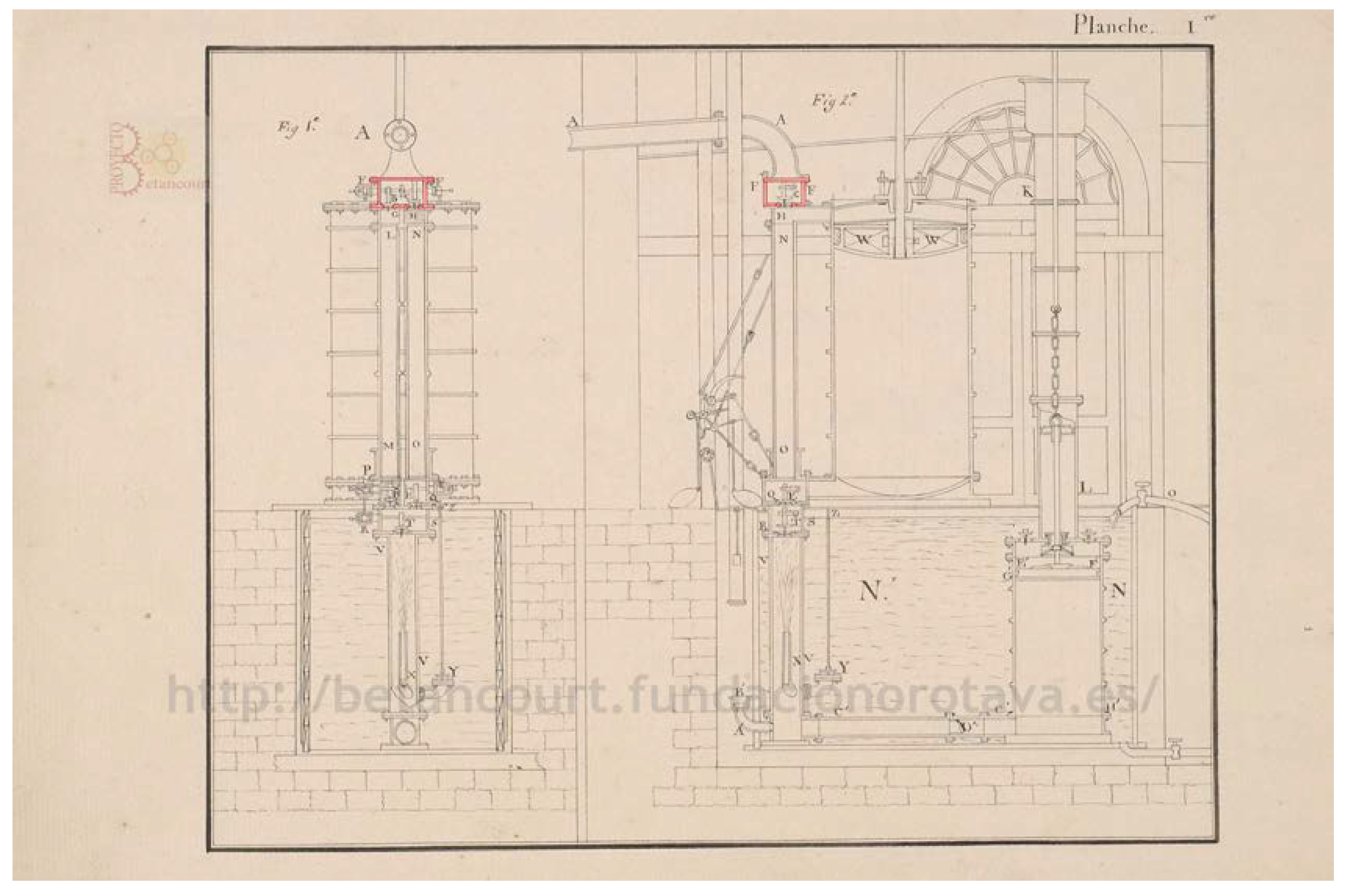
Given the complete absence of any reference dimension both in the descriptive memory and in the plates, the treatise of the time of Thomas Tredgold has been used [8]. It is explained in the article 415 [8] what are the desirable proportions of the cylinders of double-action steam machines. In particular, it is said that the stroke of the piston must be twice the internal diameter of the cylinder, establishing a cylinder of 60 cm internal diameter resulting in a stroke of 120 cm.
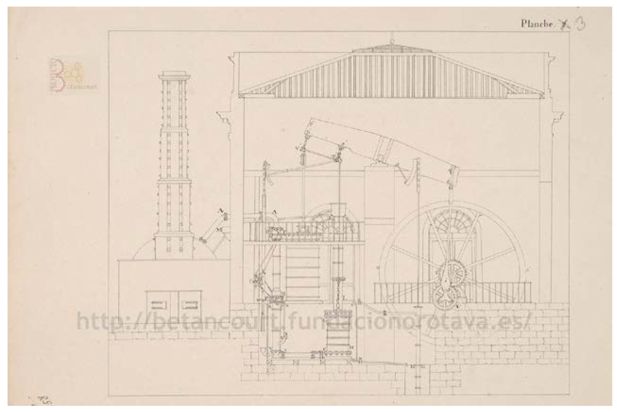
Thus, measuring the piston stroke directly on plate 1 (profile view) results in a distance of 80 mm. This means that 1200 mm in reality are 80 mm in the plane, resulting in a scale of reduction of value 1:15, for plates 1 (profile view), 2 (top view) and 3 (front view). On the other hand, in the rest of the sheets in which detailed views of other elements appear, a single scale is not used and these facilitate a better understanding of the elements and their operation (plates 4 to 6).
Therefore, if we know the value of the graphic scale (1:15), we can know the real dimensions of all the elements that make up the set.
2.1.3. Identification of the Dihedral Projections (Orthographic Views) in Each of the Main Sheets by Means of Descriptive Geometry
2.1.4. Determination of the Detailed Geometry and Direct Measurement of the Main Dimensions that Appear in the Main Sheets
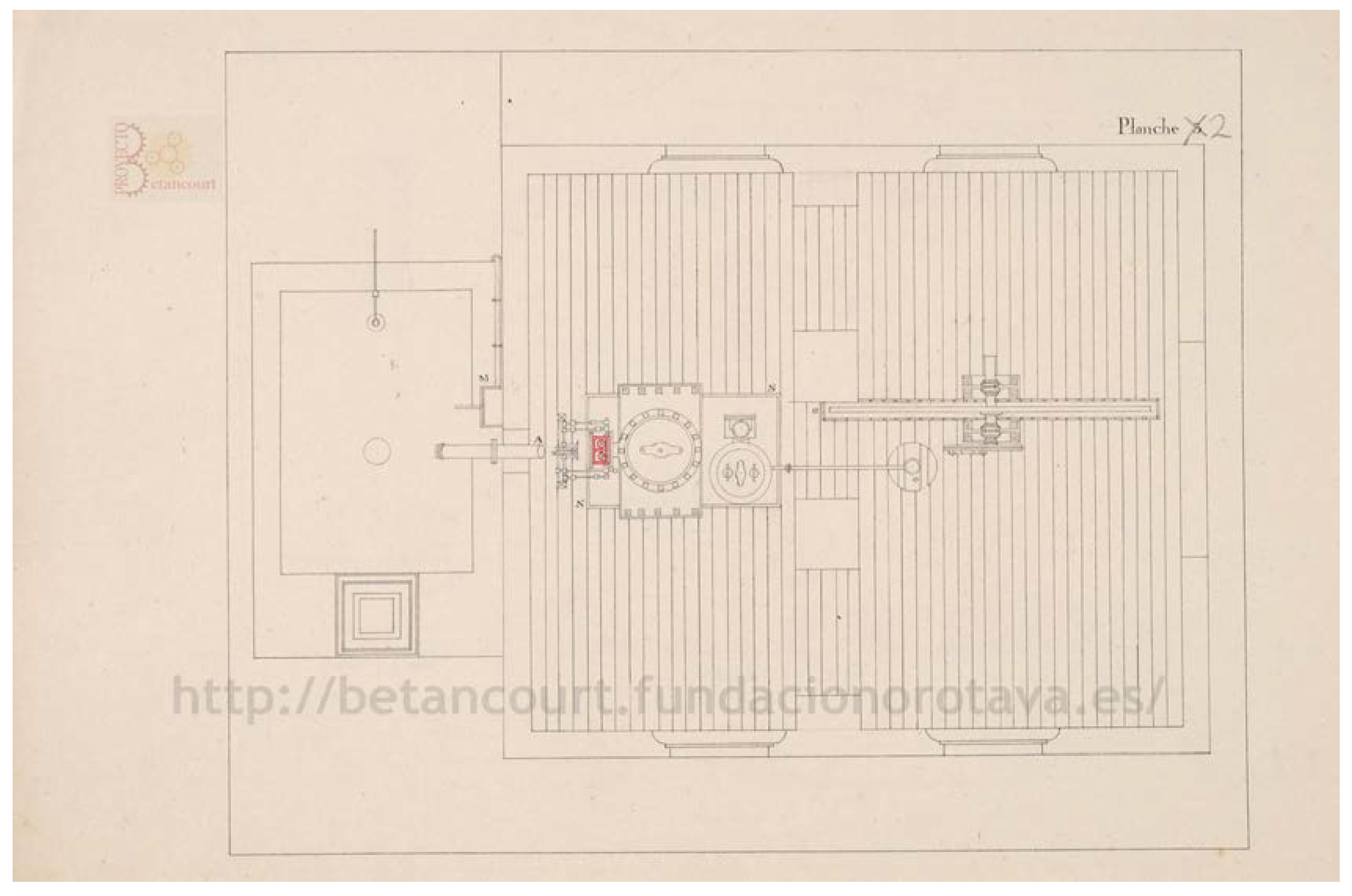
Once the element to be dimensioned has been determined and its main geometry has been visualized in the different views, its dimensioning is undertaken. The element in the plant view has a maximum dimension of 36 mm, and by applying the graphical scale of 1:15 a real value of 540 mm results. Therefore, in order to determine the rest of the dimensions we proceed in the same way.
When contrasting the orthographic views of the steam box FF that appear in the main sheets (Figure 1, Figure 2 and Figure 3), it can be seen that it resembles a little the correct solution of Figure 8, well-defined both geometrically and dimensionally.
However, it is known that the steam box accommodates two valves (B and C) that allow the entry of water vapor and the passage of steam to the lower steam box (Steam box GH), divided into compartments G and H. In a similar manner, in order to understand how the valves are housed it is necessary to understand the mechanism that moves them, explained in Figure 7. The descriptive memory explains that when one of the valves is open the other remains closed, so it is necessary to understand that both movements are related.
As can be appreciated, this information is not possible to express from three main sheets (Figure 1, Figure 2 and Figure 3), since it would be necessary to present different dihedral projections of the steam box and several longitudinal and transversal sections in order to appreciate the interior details, as well as the dimensions of all its parts. As will be understood, the descriptive memory was only intended to facilitate the understanding of its operation, and so it did not specify in detail either the dimensions or the mechanism of its operation.
For this reason, and in the absence of precise geometric information on all the parts that make up the steam box, mechanical engineering knowledge is necessary to design it correctly, since as mentioned Betancourt drew the sheets to convey the idea of its operation, and not as manufacturing and assembly plans within a standardization process. Therein lies one of the main difficulties of this research work that has involved a huge effort.
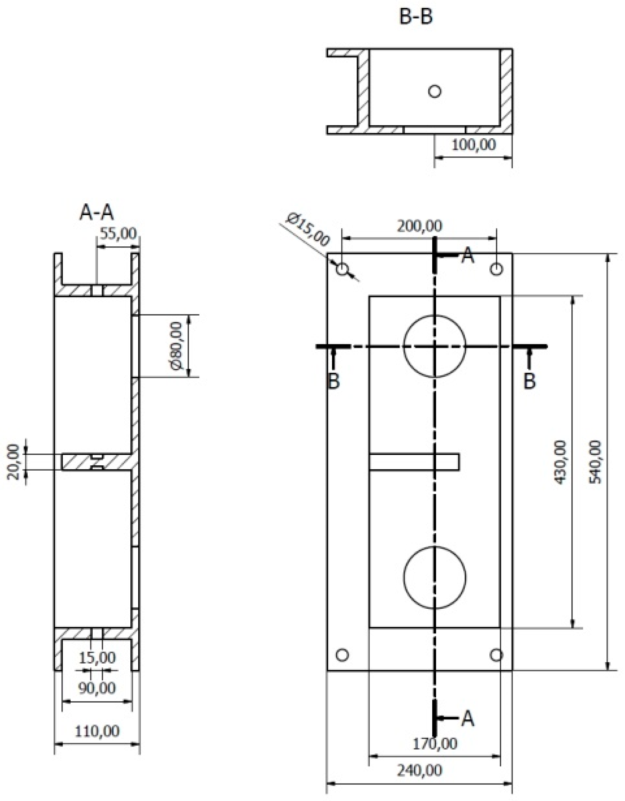
On the one hand, the steam box FF must be drilled on the sides to allow the entry of the shaft that provides the movement to valves B and C. In addition this shaft must be split, that is the left side must have an axle independent of the axle of the right side. Also, a central segmentation appears in the sheets, which must not prevent the water vapor from accessing both sides of the steam box, since the part that determines its output is the valve. This central piece (segmentation) must have a support function for the axle of the valve, and finally, the width of the walls of the steam box cannot be specified from the sheets, so we must assume a sufficient thickness knowing that it is a cast iron structure.
Finally, with all this data the steam box FF is defined geometrically and dimensioned perfectly (Figure 8).
As can also be appreciated, this geometric and dimensional definition does not exist in the sheets (Figure 1, Figure 2 and Figure 3), so it is still more justified that the 3D graphic reconstruction that could be obtained from them is not enough, but rather knowledge is necessary of mechanical engineering for its correct functional definition.
2.1.5. Obtaining the 3D Model (.ipt) with Parametric CAD Software
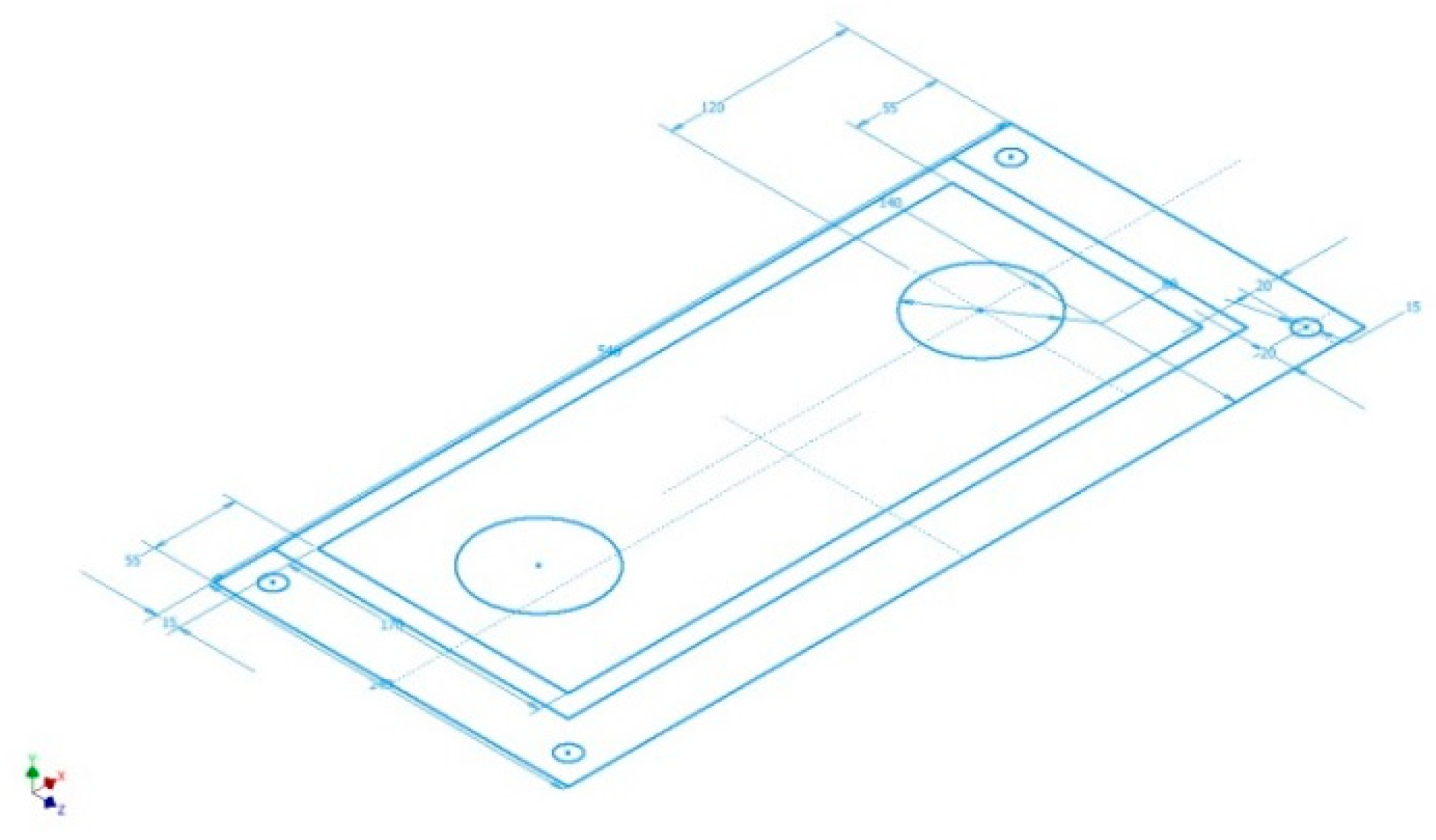
Once all the dimensions of the steam box FF are known, the starting sketch is elaborated in conventional parametric CAD software such as Autodesk Inventor Professional (Figure 9).
Next, this sketch is extruded in order to give it thickness and form a base of the element (Figure 10), and from this base all the pieces that make up the element are extruded (Figure 11, Figure 12, Figure 13 and Figure 14).
The last step to finishing the element is the creation of the holes in the outer walls of the steam box FF, necessary to accommodate the shaft that closes and opens valves B and C (Figure 14).
2.1.6. Assembly and Application of Geometric Restrictions and Movement (Degrees of Freedom) So That the Steam Box Is Coherent and Functional
The process for each of the remaining elements is similar, although the complexity of some of them implies an even more profound mechanical study. So once all the parts of the steam box have been modeled, it is necessary to assemble them.
This process requires a lot of time since the contour and behavior of each of them must be defined, which implies the use of geometric restrictions and degrees of freedom.
In the case of the steam box FF, the first step is to restrict by opposition the lower surface with the upper surface of the lower steam box (Steam box GH). In addition both boxes must be perfectly aligned and for this purpose two walls are restricted by alignment, so that the steam box FF has no degree of freedom with respect to the steam box GH. Next, the four lower screws that join it to the steam box GH are restricted by insertion, since the holes in both steam boxes are aligned.
The next step is to introduce the axes of the valves into their respective holes, defining an insertion restriction with respect to a hole. That axle has two cams where the valves are placed, and these have two bolts that are inserted into the hole of the cam. These operations are also carried out by defining the insertion restriction with respect to a hole. Figure 15, Figure 16 and Figure 17 show the final result of the assembly. It consists of a perfectly realizable box of valves, and is in agreement with the sheets and indications that exist in the descriptive memory.
3. Results and Discussion
Figure 18 shows an isometric view of the 3D CAD model of the double-acting steam engine using CAD techniques. Figure 19 offers an exploded view of the overall machine, for a better understanding of the direction and order of assembly of the different parts of the invention, and Figure 20 shows the plans of the ensemble with an indicative list of different elements.
It is not easy to describe the operation of the double-acting steam engine, and although the purpose of the manuscript is different, it is necessary to comprehend this in order to understand the enormous complexity involved in the geometric modeling process of the steam engine. For this only the explanatory memory of Betancourt himself has been available, since the existing planimetry alone is insufficient to understand its operation. Thus, all the elements have been modeled to scale from the 6 sheets of the file of the invention, and only the materials used at the time have been assigned to the models. Technically, the most difficult parts to model have been the chains, due to their complex geometry and the difficulty of defining their relationship with the surrounding elements. At the mechanical level, the other great difficulty has been understanding the access mechanisms to the different chambers, controlled by rods and valves, because although the plans reflect their existence, it was necessary to know where the supports were, and what function they had in order to coordinate the movement of the whole.
In principle, the double-acting steam engine consists of two systems that will facilitate its description (Figure 4): the hydropneumatic driving circuit and the inertial mechanism.
The hydropneumatic drive circuit consists of several elements: First of all, there is the boiler (18) where the water is heated to the highest possible temperature, producing water vapor that leaves through pipe A (20) in the direction of the steam cylinder, but before reaching it passes through the steam box FF (22) that functions as a double-acting valve. This box has an entrance hole and two exit holes. The outputs are closed by mechanical valves B and C (44), which are exclusive—this is to say that when one is open the other is closed. When open, the valve on the right connects to the lower entrance of the steam cylinder (23). Thus, the hot water vapor enters the steam cylinder chamber at high pressure and temperature by pushing the piston (27) in the vertical direction. If the hot air enters through the lower opening the movement is ascending, and if it does so through the upper one, it is descending. The water vapor that is expelled, at lower pressure and temperature, comes out through the same opening through which it entered, but this time the inlet valve B (44) is closed so it is routed to the lower steam box PQ (16).
Similarly, the PQ steam box has a valve system D and E (37) identical to that of the steam box FF. It is a coordinated system because when the upper one is closed the lower one is open, so that only the gases of lower temperature and pressure, driven by the action of the piston of the cylinder, descend through the lower steam box.
Thus, the water vapor exits through the CC pipe (12) and reaches the cylinder of the air pump (11). Both the CC pipe and the air pump are submerged in water to facilitate the cooling of water vapor, increase the temperature difference and decrease the pressure. The cooling water comes through the water pump (26) which is driven by the rocker arm itself, contributing to the even greater difference in pressures and temperatures on the two faces of the piston.
Inside the air pump there is a piston (29) of unusual characteristics, since in the piston itself there is a valve E’F’ (28) that allows passage from the lower part of the chamber to the upper one, but never in the opposite direction. In a similar way the piston of the air pump is driven by the rocker arm (2), aided by the small pressure difference of the gases inside it. The upward movement of the piston helps to evacuate the air from the upper area of the chamber by driving it through a vertical pipe that ends in a condensation hood in contact with the atmosphere. In this hood part of the water vapor is condensed and channeled through the return pipe M (19), which again conducts water vapor to the boiler (18). Finally, the water vapor condenses again in the boiler and returns to the circuit.
The hydropneumatic circuit also has several regulation mechanisms. First, in the steam box RS (15) located in the lower area of the pipe there is a valve T (36) that allows restriction of the output of water vapor at a lower cylinder temperature. The opening of this valve causes the speed of the piston to vary since it can hinder the evacuation of gases from it. To control this opening there is the speed moderator (17) or key that regulates its opening. On the other hand, in case there is not enough water to cool the pump and lower pipes the CC pipe (12) has a Y valve (13) that is opened by the Z valve (14) when the water level decreases, communicating the pipe with the atmosphere, and stopping the process in a few seconds. Similarly, in order to facilitate the exit of the water that may have condensed in the lower pipe there is also an opening which confers to valve B’ (32) the ease of purging in the event of a stoppage of the mechanism.
On the other hand, the inertial mechanism also consists of several elements. First, the piston of the steam cylinder (27) drives the rocker arm (2). However, the piston is not directly attached to the rocker arm but to a metal bar frame that is solidly attached to the rocker arm, and the end of the piston is attached to the rod R’V’ (24). The movement of the piston causes the rocker arm to pitch, and this has at its opposite end a connecting rod q (3) to which another connecting rod i (4) is attached. Connecting rod i is joined at its other end to an eccentric cogwheel x’ (9) through a fixing plate (10), and this gear moves in turn like a planetary gear system that would be another cogwheel z’ (6) attached to the inertia flywheel shaft (7). Finally, the shaft would be solidly joined to the inertia flywheel (5) of large dimensions in order to achieve a regular rotation movement. As can be seen, this system transforms the reciprocating movement of the piston into another rotary of the inertia flywheel, and a multitude of devices could be connected to this flywheel and would move automatically.
To finish describing the invention, two more aspects have to be mentioned: On the one hand, the movement of the rocker arm is responsible for the movement of the air pump (11). The rocker arm metal frame has a rod S’T’ (25) to which is attached the end of the piston shaft of said pump, and the pitch of the rocker arm causes the rise and fall of the shaft.
On the other hand, a chain of links holding a pq beam (45) hangs from the end of the metal frame. The ascending and descending movement of this beam makes the rods responsible for opening and closing the different steam valves work. In addition, in order to provide robustness to the support Betancourt plans to hang a counterweight KL (33) from its end so that it does not swing excessively.
An interesting observation can be made here. Looking at the mechanism in profile one can imagine a balanced rocker arm—that is to say that an energetic symmetry is proposed on both sides of the rocker arm. The objective would be to follow the law of conservation of energy in the operation of this engine as a particular example of industrial architecture [27]. The axis of this symmetry is the support of the parallelogram where its shaft rests: On the left they present calorific energy, and on the right mechanical energy, the rocker arm acting as a transforming element from one to the other. This energetic symmetry is almost a geometric symmetry, because if the system were not balanced it would make no sense to make the rocker arm shaft its geometric center.
4. Conclusions
This paper shows the result of the complex process carried out in order to obtain a geometric modeling and virtual recreation of the double-acting steam engine designed by Agustín de Betancourt in 1789, thanks to the Autodesk Inventor Professional software.
The methodology employed here corresponds to empirical techniques based on the knowledge of descriptive geometry used to identify the orthographic views (front, top and profile) on the printed sheets of the invention, thus determining the main geometry of all the elements of the set as well as the measurement of its main dimensions. However, there was an absence of detailed geometric information regarding the different elements in the sheets and how each one of them was assembled so that the set would work properly. Therefore, a series of dimensional hypotheses and geometric restrictions and degrees of freedom have been established from the point of view of engineering mechanics, in order to obtain a coherent 3D CAD model of the set.
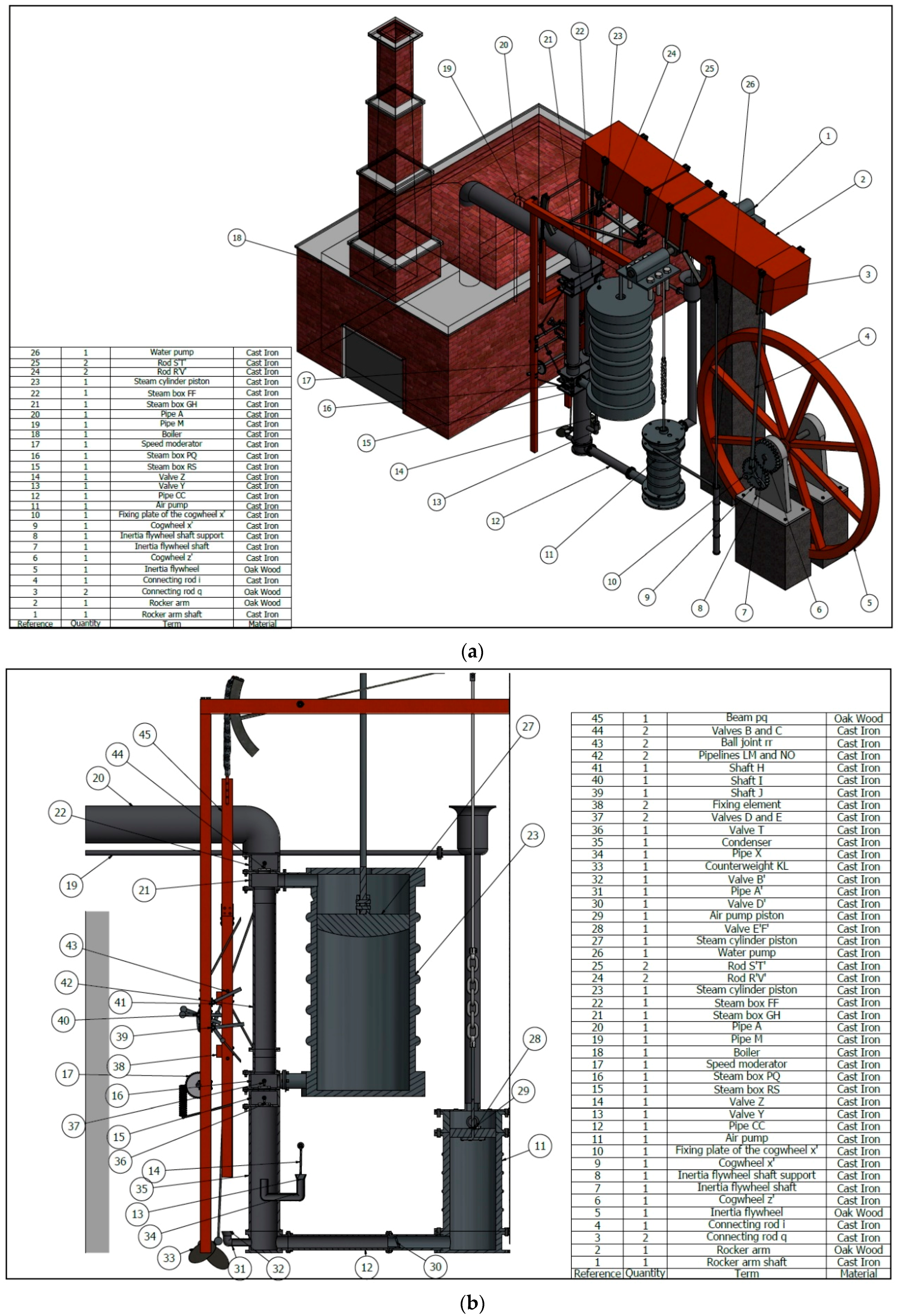
After obtaining the 3D CAD model of the whole, a complete geometric documentation of the engine has been generated. Thus, an exploded view has been obtained that shows the order of assembly of the different elements as well as certain plans of the set (perspective and cross-section). Here all the model’s elements represented by references are shown, and with indications of their term and material. This has allowed us to obtain a complete description of its operation for the reader’s definitive understanding of this engine, a task that has not been easy and is not explained in any scientific documentation.
Finally, this process of geometric modeling has enabled us to learn that the system is balanced with the geometric center of the rocker arm shaft, and presents an energetic symmetry whose axis is the support of the parallelogram where the shaft rests: calorific energy to the left and mechanical energy to the right, with the rocker arm acting as a transforming element from one to the other. This has allowed us to discover that idea, which remains constant in all of Betancourt’s designs.
Author Contributions
Formal analysis, B.G.-M. and E.D.l.M.-D.l.F.; funding acquisition, J.I.R.-S.; investigation, J.I.R.-S.; methodology, B.G.-M. and E.D.l.M.-D.l.F.; project administration, J.I.R.-S.; supervision, J.I.R.-S.; validation, E.D.l.M.-D.l.F.; visualization, J.I.R.-S.; writing–original draft, J.I.R.-S. and E.D.l.M.-D.l.F.; writing–review and editing, J.I.R.-S. and E.D.l.M.-D.l.F.
Funding
This research was funded by the Spanish Ministry of Economic Affairs and Competitiveness, under the Spanish Plan of Scientific and Technical Research and Innovation (2013–2016), and European Fund Regional Development (FEDER) under grant number [HAR2015-63503-P].
Acknowledgments
We are very grateful to the Fundación Canaria Orotava de Historia de la Ciencia for permission to use the material of Project Betancourt available at their website. Also, we sincerely appreciate the work of the reviewers of this article.
Conflicts of Interest
The authors declare no conflicts of interest.
References
- Muñoz Bravo, J. Biografía Cronológica de Don Agustín de Betancourt y Molina en el 250 Aniversario de su Nacimiento; Acciona Infraestructuras: Murcia, Spain, 2008. (In Spanish) [Google Scholar]
- Bogoliúbov, A.N. Agustín de Betancourt: Un Héroe Español del Progreso; Seminarios y Ediciones: Madrid, Spain, 1973. (In Spanish) [Google Scholar]
- Martín Medina, A. Agustín de Betancourt y Molina; Dykinson: Madrid, Spain, 2006. (In Spanish) [Google Scholar]
- Rojas-Sola, J.I.; De la Morena-de la Fuente, E. Agustin de Betancourt’s wind machine for draining marshy ground: Approach to its geometric modeling with Autodesk Inventor Professional. Technologies 2017, 5, 2. [Google Scholar] [CrossRef]
- Rojas-Sola, J.I.; De la Morena-de la Fuente, E. Digital 3D reconstruction of Agustin de Betancourt’s historical heritage: The dredging machine of the port of Krondstadt. Virtual Archaeol. Rev. 2018, 9, 44–56. [Google Scholar] [CrossRef]
- Principles of Seville. Available online: http://smartheritage.com/wp-content/uploads/2016/06/PRINCIPIOS-DE-SEVILLA.pdf (accessed on 19 August 2018).
- London Charter. Available online: http://www.londoncharter.org (accessed on 19 August 2018).
- Tredgold, T.E. Tratado de las Máquinas de Vapor y de su Aplicación a la Navegación, Minas, Manufacturas etc.; Imprenta de D. León Amarita: Madrid, Spain, 1831. [Google Scholar]
- Payen, M.J. Betancourt et l’introduction en France de la machine à vapeur à double effet. Rev. D’Hist. Sci. Leurs Appl. 1967, 20, 187–198. [Google Scholar] [CrossRef]
- Company, P.; Contero, M.; Conesa, J.; Piquer, A. An optimization-based reconstruction engine for 3D modeling by sketching. Comput. Graph. 2004, 28, 955–979. [Google Scholar] [CrossRef]
- Naya, F.; Conesa, J.; Contero, M.; Company, P.; Jorge, J. Smart sketch system for 3D reconstruction based modeling. In Smart Graphics; Butz, A., Kruger, A., Olivier, P., Eds.; Lecture Notes in Computer Science; Springer: Berlin/Heidelberg, Germany, 2003; Volume 2733, pp. 58–68. [Google Scholar]
- Piquer, A.; Martin, M.; Company, P. Skewed mirror symmetry for depth estimation in 3D line-drawings. In Graphics Recognition: Recent Advances and Perspectives; Llados, J., Kwon, Y.B., Eds.; Lecture Notes in Computer Science; Springer: Berlin/Heidelberg, Germany, 2004; Volume 3088, pp. 142–153. [Google Scholar]
- Olsen, L.; Samavati, F.F.; Sousa, M.C.; Jorge, J.A. Sketch-based modeling: A survey. Comput. Graph. 2009, 33, 85–103. [Google Scholar] [CrossRef]
- Company, P.; Piquer, A.; Contero, M.; Naya, F. A survey on geometrical reconstruction as a core technology to sketch-based modeling. Comput. Graph. 2005, 29, 892–904. [Google Scholar] [CrossRef] [Green Version]
- Barton, M.; Pottmann, H.; Wallner, J. Detection and reconstruction of freeform sweeps. Comput. Graph. Forum 2014, 33, 23–32. [Google Scholar] [CrossRef]
- Furferi, R.; Governi, L.; Volpe, Y.; Puggelli, L.; Vanni, N.; Carfagni, M. From 2D to 2.5D i.e., from painting to tactile model. Graph. Models 2014, 76, 706–723. [Google Scholar] [CrossRef]
- Fu, H.; Zhou, S.; Liu, L.; Mitra, N.J. Animated constructions of line drawings. ACM Trans. Graph. 2014, 30, 133. [Google Scholar] [CrossRef]
- Shlyakhter, I.; Rozenoer, M.; Dorsey, J.; Teller, S. Reconstructing 3D tree models from instrumented photographs. IEEE Comput. Graph. Appl. 2001, 21, 53–61. [Google Scholar] [CrossRef]
- Kim, J. Modeling and optimization of a tree based on virtual reality for immersive virtual landscape generation. Symmetry 2016, 8, 93. [Google Scholar] [CrossRef]
- Piquer, A.; Company, P. State of the art of 3D reconstruction of line-drawings. Inform. Tecnol. 2004, 15, 71–80. [Google Scholar] [CrossRef]
- Neumüller, M.; Reichinger, A.; Rist, F.; Kern, C. 3D printing for cultural heritage: Preservation, accessibility, research and education. In 3D Research Challenges in Cultural Heritage; Ioannides, M., Quak, E., Eds.; Lecture Notes in Computer Science; Springer: Berlin/Heidelberg, Germany, 2014; Volume 8355, pp. 119–134. [Google Scholar]
- Tashi, A.S.U.; Watanabe, M.; Kubo, A. Analytical Point-Cloud Based Geometric Modeling for Additive Manufacturing and its application to Cultural Heritage Preservation. Appl. Sci. 2018, 8, 656. [Google Scholar] [CrossRef]
- Varady, T.; Martin, R.R.; Cox, J. Reverse engineering of geometric models-an introduction. Comput. Aided Design 1997, 29, 255–268. [Google Scholar] [CrossRef]
- Betancourt, A. Mémoire sur Une Machine à Vapeur à Double Effet; Academy of Sciences: París, France, 1789; Available online: http://fundacionorotava.es/pynakes/lise/betan_doubl_fr_01_1789 (accessed on 19 August 2018).
- Wu, Y.; He, F.; Han, S. Collaborative CAD synchronization based on a symmetric and consistent modeling procedure. Symmetry 2017, 9, 59. [Google Scholar] [CrossRef]
- Shih, R.H. Parametric Modeling with Autodesk Inventor 2016; SDC Publications: Mission, KS, USA, 2015; ISBN 978-1-63057-030-9. [Google Scholar]
- Bravo, J.C.; Castilla, M.V. Energy conservation law in industrial architecture: An approach through geometric algebra. Symmetry 2016, 8, 92. [Google Scholar] [CrossRef]
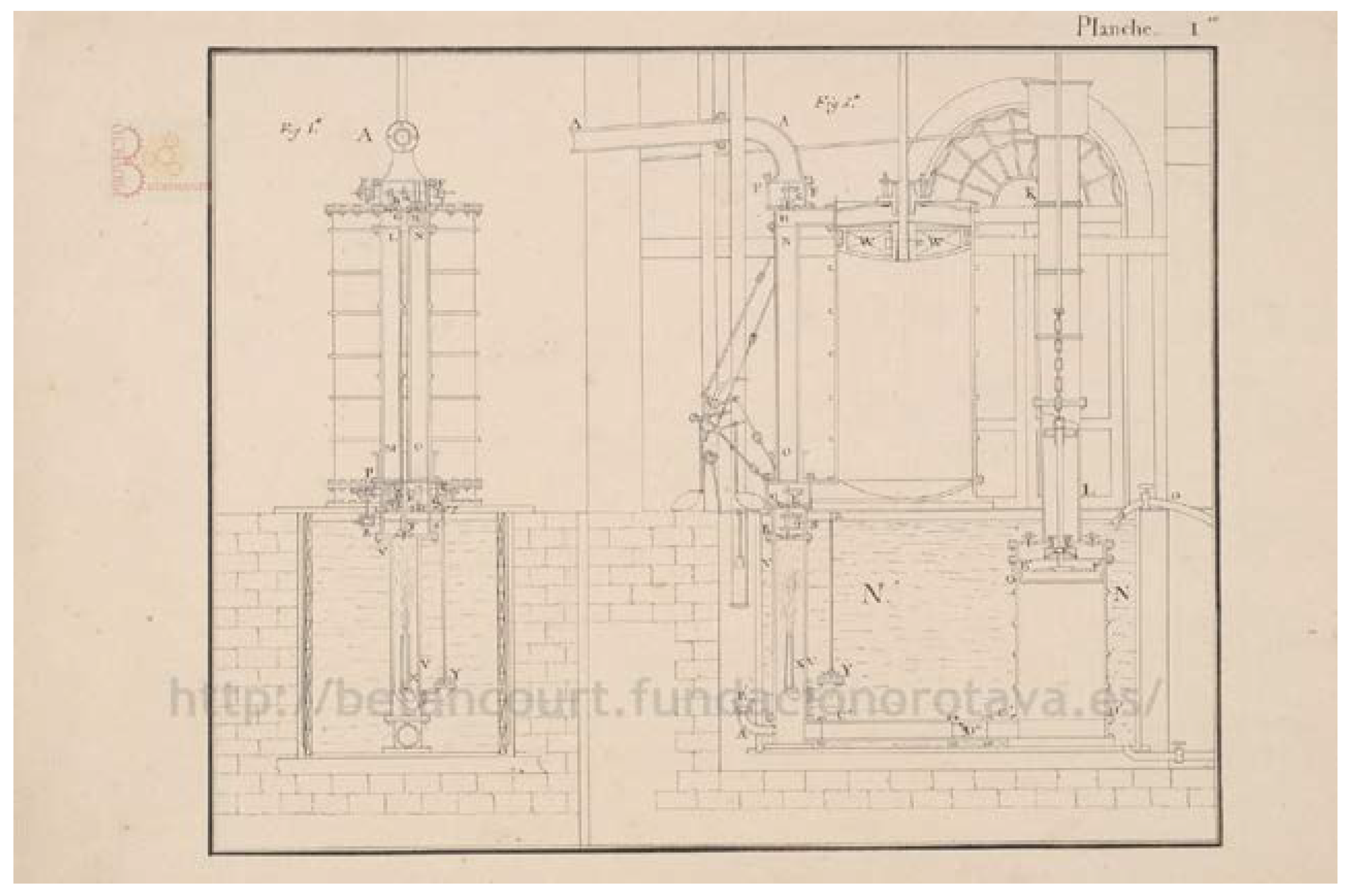
Figure 1.
Agustín de Betancourt’s double-acting steam engine (Front view) (courtesy of Fundación Canaria Orotava de Historia de la Ciencia).
Figure 1.
Agustín de Betancourt’s double-acting steam engine (Front view) (courtesy of Fundación Canaria Orotava de Historia de la Ciencia).

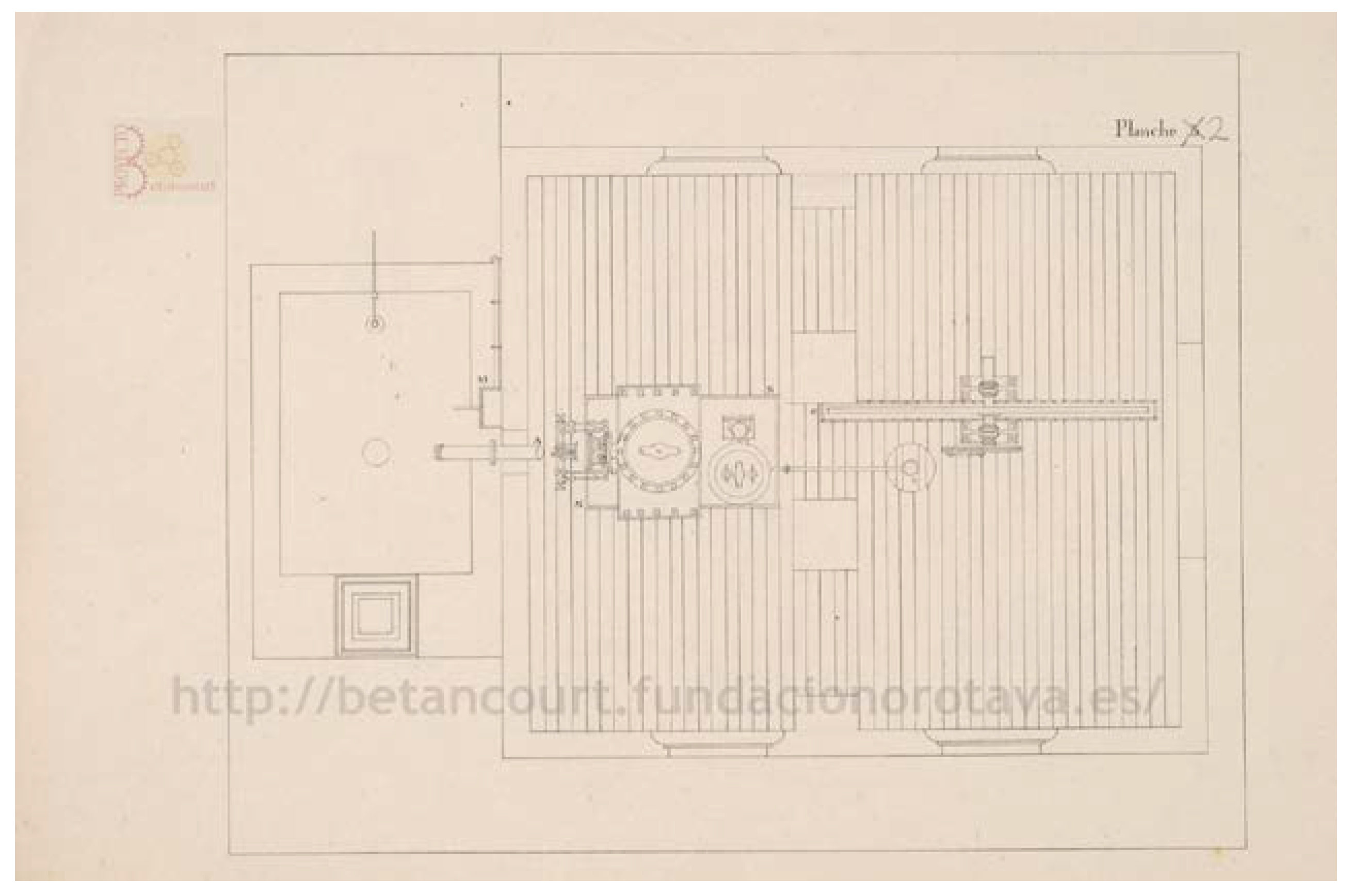
Figure 2.
Agustín de Betancourt’s double-acting steam engine (Top view) (courtesy of Fundación Canaria Orotava de Historia de la Ciencia).
Figure 2.
Agustín de Betancourt’s double-acting steam engine (Top view) (courtesy of Fundación Canaria Orotava de Historia de la Ciencia).

Figure 3.
Agustín de Betancourt’s double-acting steam engine (Profile view) (courtesy of Fundación Canaria Orotava de Historia de la Ciencia).
Figure 3.
Agustín de Betancourt’s double-acting steam engine (Profile view) (courtesy of Fundación Canaria Orotava de Historia de la Ciencia).

Figure 4.
Location of the FF steam box (in red) in the front view (elevation).

Figure 5.
Location of the FF steam box (in red) in the top view.

Figure 6.
Location of the FF steam box (in red) in the profile view.

Figure 7.
Detail drawing explaining the operation of the valve-regulating mechanism of the double-action steam engine (steam box FF in red) (courtesy of Fundación Canaria Orotava de Historia de la Ciencia).
Figure 7.
Detail drawing explaining the operation of the valve-regulating mechanism of the double-action steam engine (steam box FF in red) (courtesy of Fundación Canaria Orotava de Historia de la Ciencia).

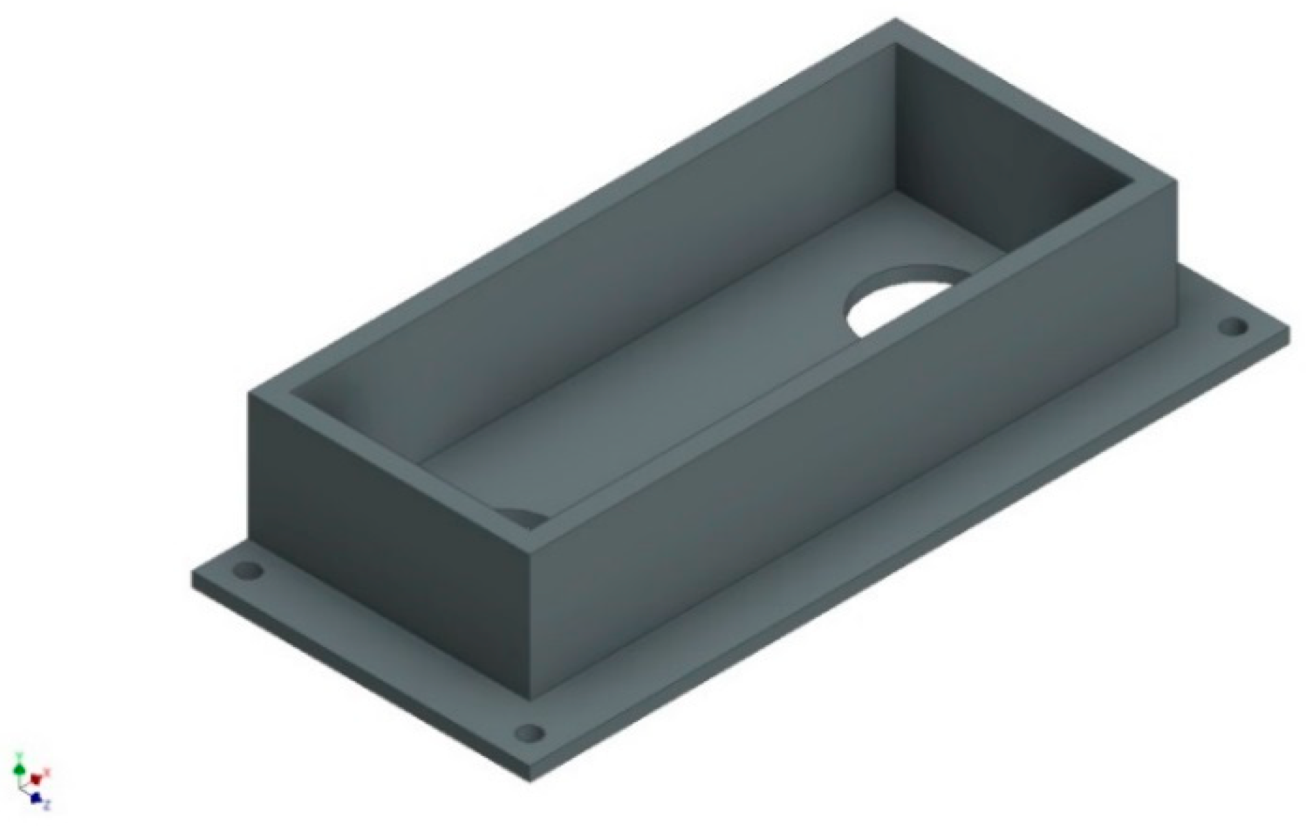
Figure 8.
Geometric and dimensional definition of the steam box FF.

Figure 9.
Profile of steam box FF.

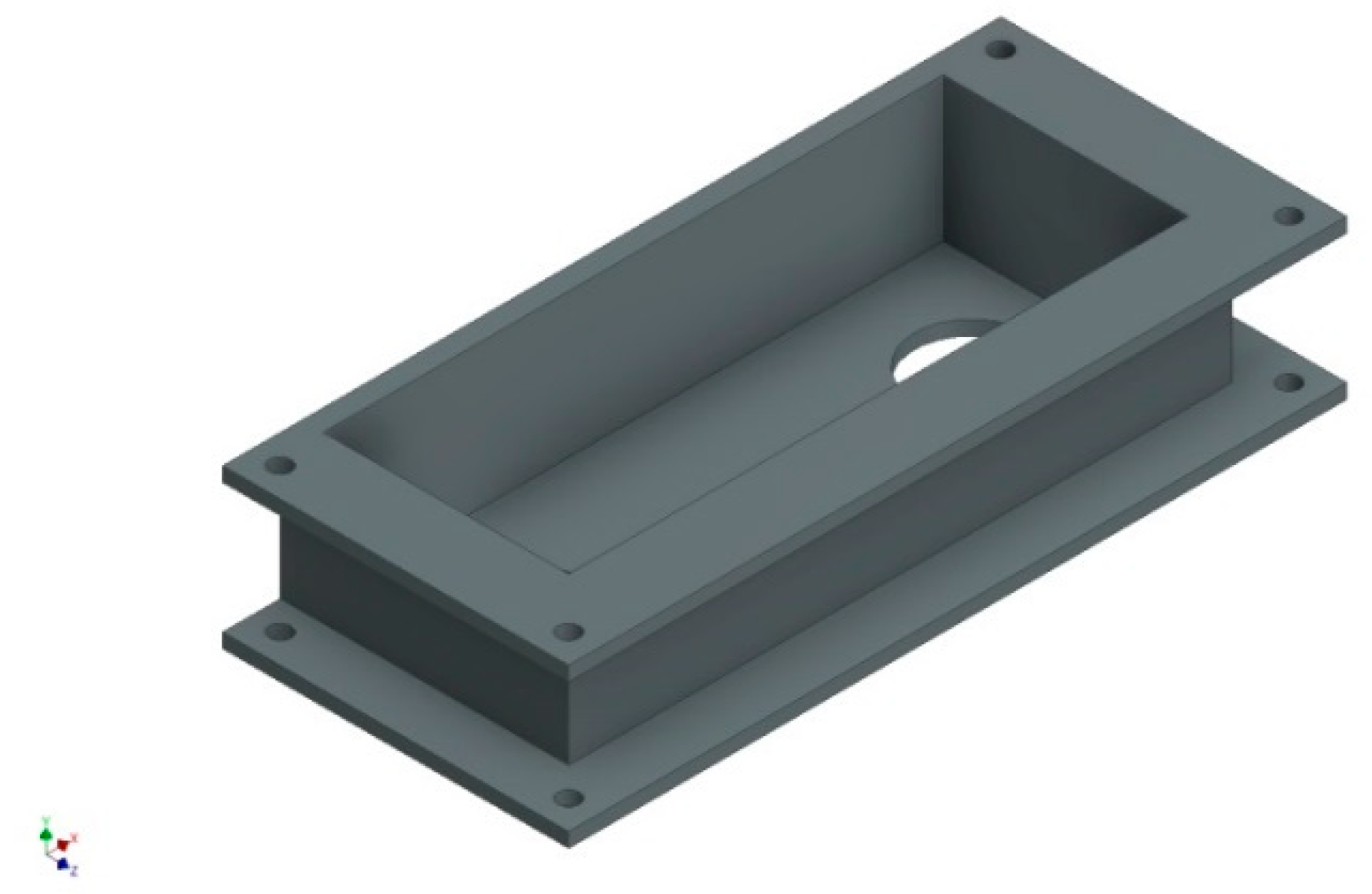
Figure 10.
Extrusion of the base of the steam box FF.

Figure 11.
Extrusion of the walls of the steam box FF.

Figure 12.
Extrusion of the upper part of the steam box FF.

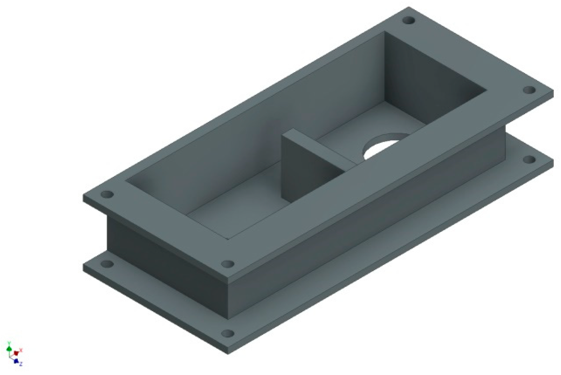
Figure 13.
Extrusion of the intermediate segmentation that divides the steam box FF.

Figure 14.
Creation of the holes that support the axle of valves B and C.

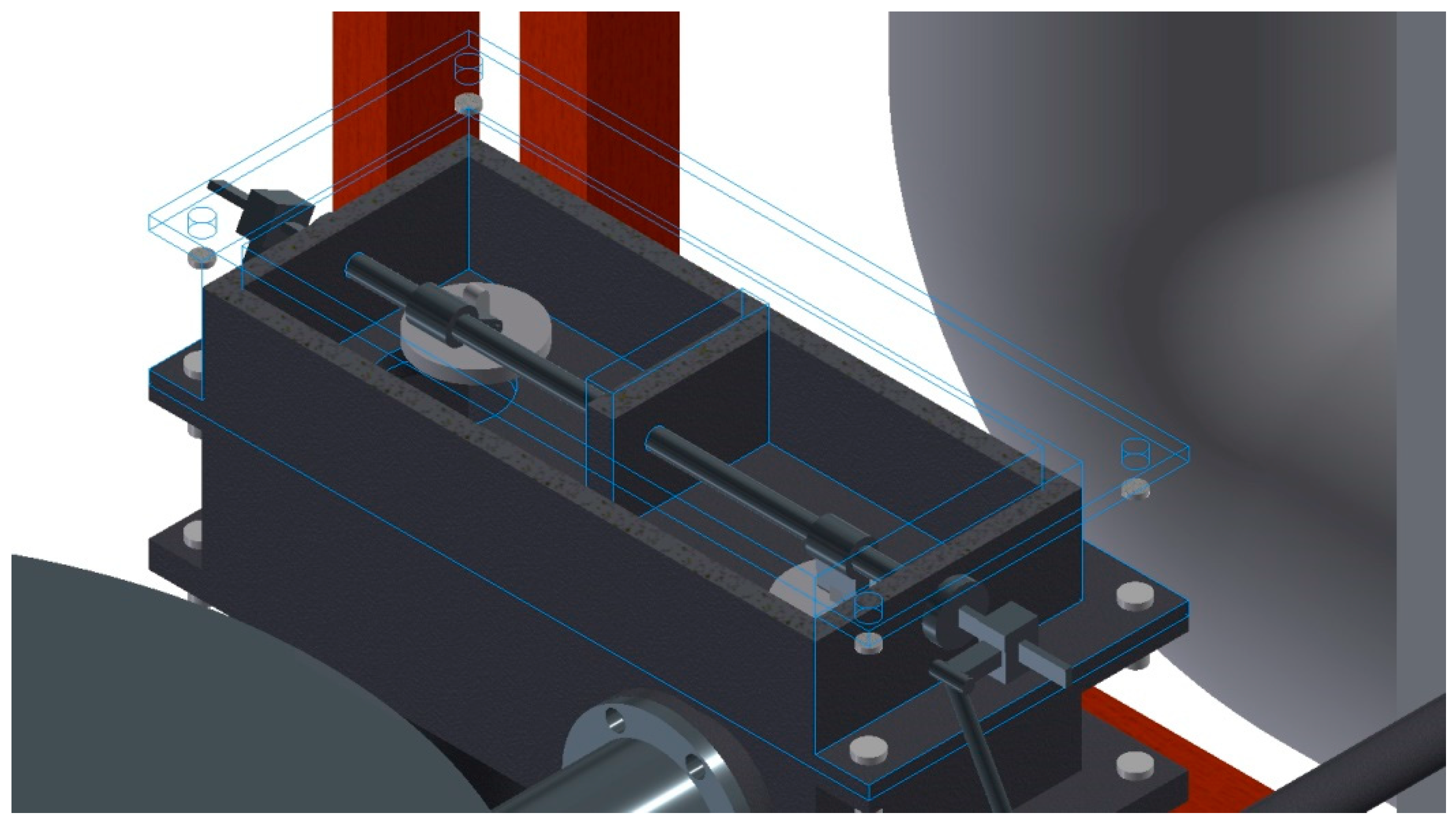
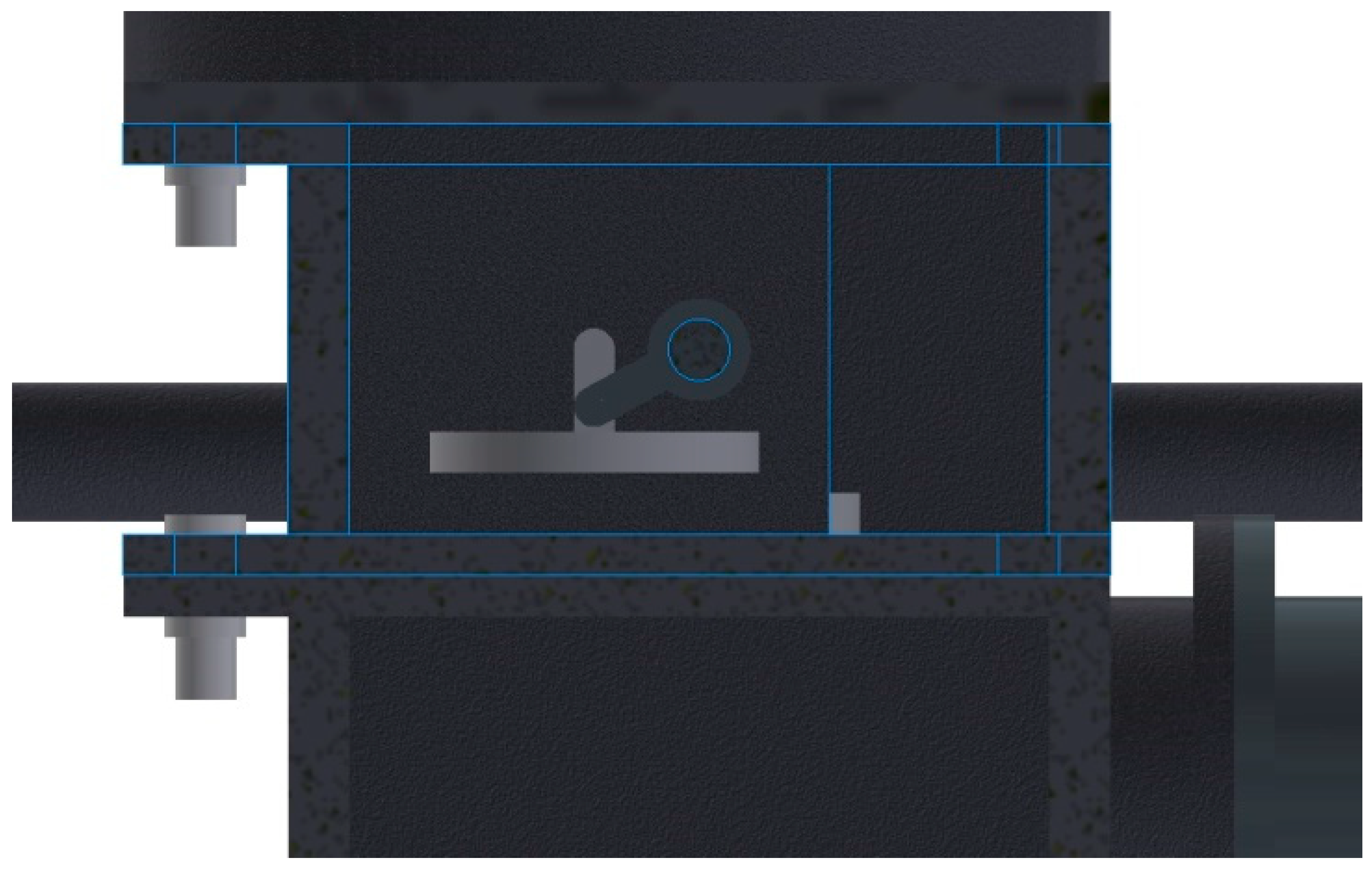
Figure 15.
Axonometric view with longitudinal section of the steam box FF to observe the valve system.
Figure 15.
Axonometric view with longitudinal section of the steam box FF to observe the valve system.

Figure 16.
Cross-section of the steam box FF to observe valve B of the steam box.

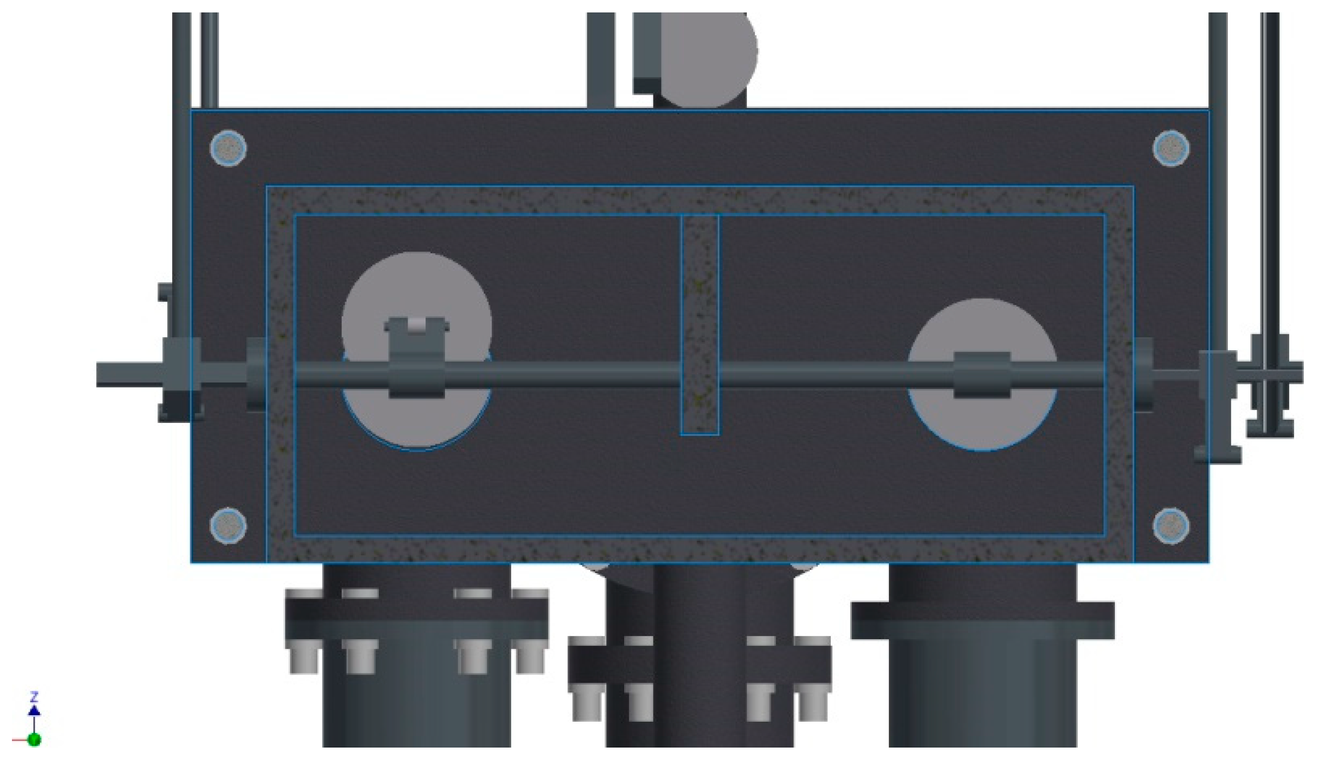
Figure 17.
Top view with longitudinal section of the steam box FF to observe the valves and the internal mechanism that controls its opening.
Figure 17.
Top view with longitudinal section of the steam box FF to observe the valves and the internal mechanism that controls its opening.

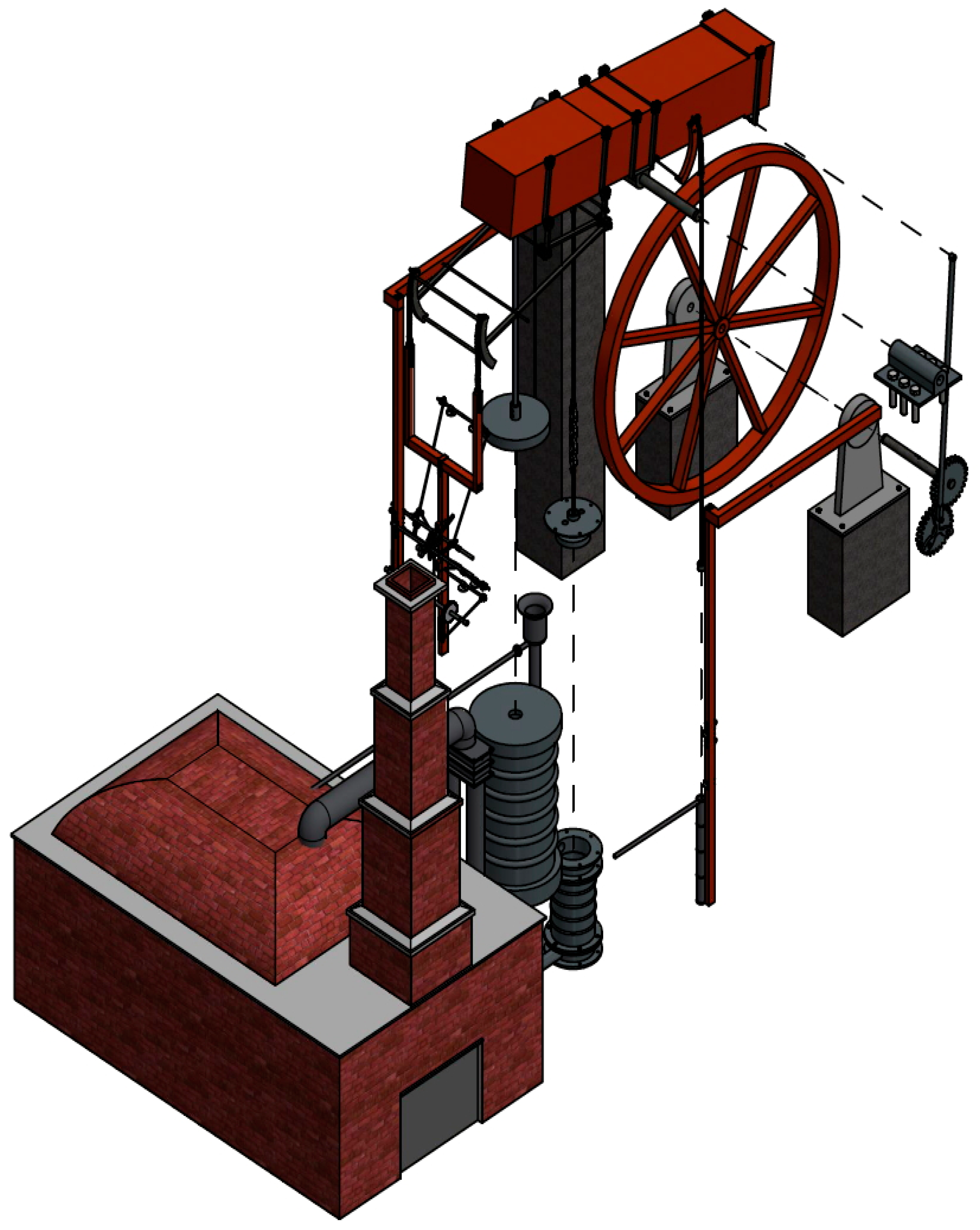
Figure 18.
Isometric view of the 3D CAD model.

Figure 19.
Exploded view of the 3D CAD model.

Figure 20.
Plans of the ensemble: (a) perspective and (b) cross-section.

© 2018 by the authors. Licensee MDPI, Basel, Switzerland. This article is an open access article distributed under the terms and conditions of the Creative Commons Attribution (CC BY) license (http://creativecommons.org/licenses/by/4.0/).
Share and Cite
MDPI and ACS Style
Rojas-Sola, J.I.; Galán-Moral, B.; De la Morena-De la Fuente, E. Agustín de Betancourt’s Double-Acting Steam Engine: Geometric Modeling and Virtual Reconstruction. Symmetry 2018, 10, 351. https://doi.org/10.3390/sym10080351
AMA Style
Rojas-Sola JI, Galán-Moral B, De la Morena-De la Fuente E. Agustín de Betancourt’s Double-Acting Steam Engine: Geometric Modeling and Virtual Reconstruction. Symmetry. 2018; 10(8):351. https://doi.org/10.3390/sym10080351
Chicago/Turabian StyleRojas-Sola, José Ignacio, Belén Galán-Moral, and Eduardo De la Morena-De la Fuente. 2018. "Agustín de Betancourt’s Double-Acting Steam Engine: Geometric Modeling and Virtual Reconstruction" Symmetry 10, no. 8: 351. https://doi.org/10.3390/sym10080351
Note that from the first issue of 2016, this journal uses article numbers instead of page numbers. See further details here.