
Can the Comparisons of Feature Locations Explain the Difficulty in Discriminating Mirror-Reflected Pairs of Geometrical Figures from Disoriented Identical Pairs?

Abstract
: The present experiment investigates whether patterns of shifts of feature locations could affect the same/different decisions of simultaneously presented pairs of geometrical figures. A shift of locations was defined as the angular distance from the location of a feature in one figure to the location of the same feature in another figure. It was hypothesized that the difficulty in discriminating mirror-reflected (or axisymmetric) pairs from disoriented identical pairs was caused by complex shifting patterns inherent in axisymmetric pairs. According to the shifts of the locations of the four structural features, five pair types were prepared. They could be ordered from completely identical to completely different in their shifts: identical 0/4 pairs, non-identical 1/4 pairs, non-identical 2/4 pairs = axisymmetric 2/4 pairs and non-identical 4/4 pairs. The latencies for non-identical pairs decreased with the increase of difference in the shifts of feature locations, indicating that serial, self-terminating comparisons of the shifts were applied to the discrimination of non-identical pairs from identical pairs. However, the longer latencies in axisymmetric 2/4 pairs than in non-identical 2/4 pairs suggested that the difficulty for axisymmetric pairs was not caused by the complex shifting patterns, and the difficulty was not satisfactorily explained by the comparisons of feature locations.1. Introduction
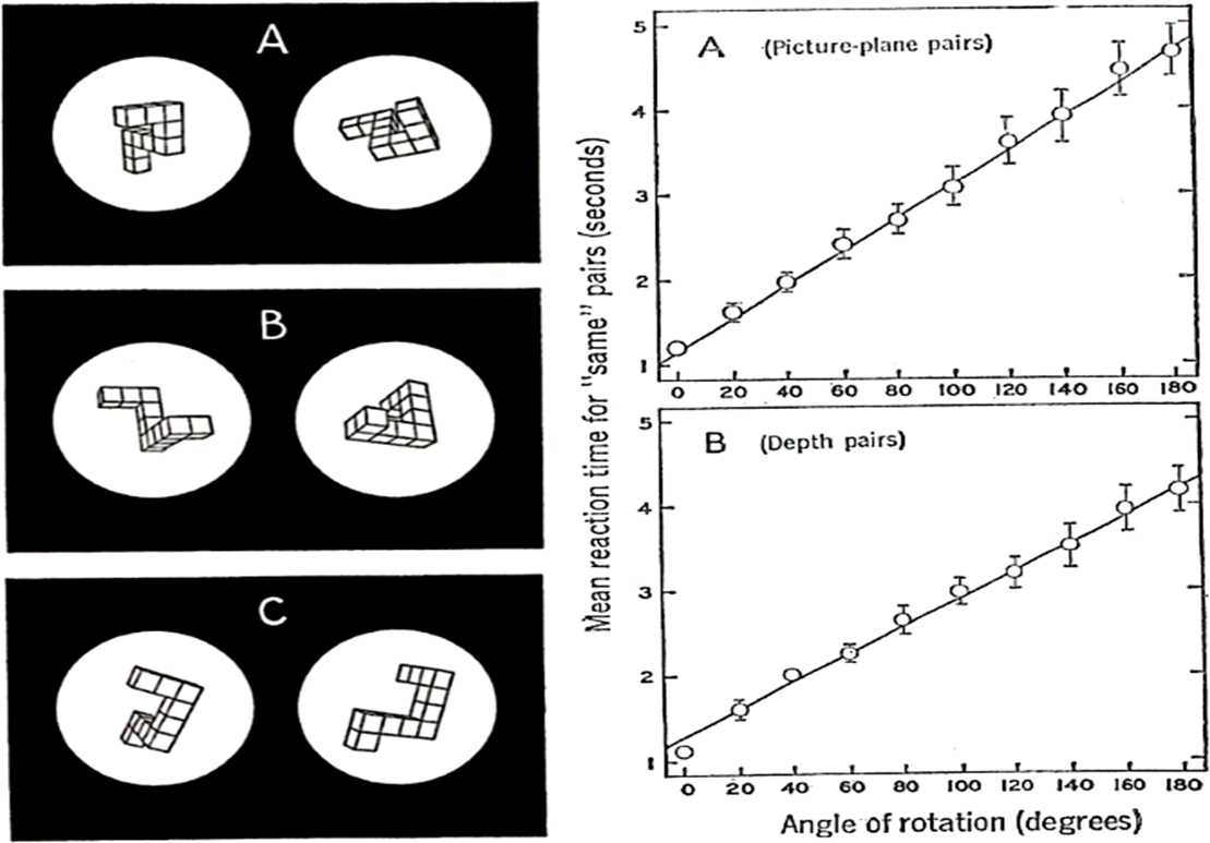
A phenomenon called mental rotation is widely accepted as a means for the recognition of disoriented figures. In their famous study, Shepard and Metzler [1] asked participants to decide whether a presented pair of objects drawn on a picture at different portrayed orientations were the same or mirror-reflected. The results of the experiment showed that the decision latencies increased linearly with the angular distance between the two orientations (Figure 1). The authors considered that, irrespective of their orientations, identity decisions about the objects could be derived from “mental rotation in three-dimensional space”.
In same/different decisions on pairs of figures with different orientations, the rate of mental rotation is typically expressed by a coefficient of latency (in ms) and angular distance (in degrees) between the two figures of the same pairs. This coefficient is equivalent to the slope of a linear regression. If the rate is high (i.e., the slope is steep), mental rotation is slow, and if the rate is low (i.e., the slope is shallow), mental rotation is fast. Mental rotation is often assumed as a continuous and holistic process analogous to the physical rotation process of an object (viz., analog view on mental rotation; see [2]), and as its corollary, the rates of mental rotation should not be affected by the conceptual characteristics of stimuli, like their complexity [3].
In fact, the effect of complexity on rotation rates was not found in earlier studies [4,5]. However, such a purely analog view of figural recognition is basically not compatible with the feature comparison position. Subsequently, the presence of the complexity effect (viz., higher rates for increased complexity of figures) became apparent with stimuli whose redundant feature information was experimentally controlled [6]. It was also found that practice and memorization procedures decrease the rates of mental rotation [7,8]. The discriminability of figures also affects the rates of mental rotation. Meaningless novel stimuli [9,10], high similarity between pairs of stimulus figures [11], and 3D stimuli compared with 2D stimuli [12] tend to raise the rates, thus slowing mental rotation.
Since the publication of the study of Shepard and Metzler, a large number of experiments have been conducted with various tasks and various stimuli. Cohen and Kubovy [13] set a limiting rate of 1 ms/°, below which the process of mental rotation was considered not to be involved in figure discriminations. For example, studies requiring participants to name disoriented alphanumeric characters [14], the letter/digit distinction of disoriented alphanumeric characters [15], the naming of disoriented drawings of natural objects [16] and top/bottom decisions of the location of a dot mark near the top or bottom of disoriented objects [17] resulted in mental rotation rates of less than 1 ms/°. In contrast, the same/mirror-reflected decisions about 3D objects [1,6,18], the same/different matching of the surfaces of cubes [19] and the same/mutant decision about randomly generated polygons [11] are examples of studies in which the rates of mental rotation were greater than 20 ms/°.
Despite the analog view on the recognition of figures, there are researches claiming that people have sensitivity to deeper geometrical properties. Bedford [20] explained by using Klein’s grouping of transformations that there are five geometries ordered from the most specific (i.e., superficial) to the most general (i.e., deep): Euclidean, similarity, affine, projective and topological. In Euclidean geometry, a figure is equivalent, even though its location is altered in its entirety. In similarity geometry, a figure is equivalent even though its size is altered uniformly. In affine geometry, a figure is equivalent even though its angle is altered (e.g., a square and a rhombus are equivalent). In projective geometry, a figure is equivalent even though the parallelism of its lines is altered (e.g., a square and a trapezoid are equivalent). In topological geometry, a figure is equivalent even though its collinearity of points (among which straight or curved lines are spanned) is altered (e.g., a circle and a rectangle are equivalent). That is, the property of a geometry is the property invariant after the transformation of the geometry. The more general the geometry is, the more the properties of specific geometries are altered.
For example, Wagemans, van Gool, Lamote and Foster [21] followed from their results that people could identify pairs of figures as identical after affine transformation. Wagemans, Lamote and van Gool [22] compared the perceived resemblance of “projectively equivalent” pairs of figures with that of more specific “perspectively equivalent” pairs of figures. The results showed that people judged both types of pairs as identical, although there was a preference toward equivalent pairs after perspective transformation compared to equivalent pairs after projective transformation. There are a number of studies supporting sensitivity to topologically invariant properties that have accumulated (e.g., [23–28]).
This study attempts to investigate whether comparisons of the locations of topologically-equivalent properties could be utilized for the recognition of figures. Especially, the attempt was directed at the question of why mirror-reflected figures are difficult to discriminate from disoriented identical figures from the standpoint of comparisons of feature locations by using (6 point, n line) figures as stimuli. A (6 point, n line) figure, or a (6, n) figure, is a figure drawn on the picture plane made up of the six points, which are located at the vertices of an invisible regular hexagon, and the n line segments, which are respectively spanned between n discrete pairs of the points.
In a same/different decision task using (6, 3) and (6, 5) figures with varied conditions, Kanbe [29] compared latencies among three types of pairs in a series of experiments: identical, isomorphic and non-isomorphic pairs. Here, an identical pair indicated that the two figures were identical in shape, size and orientation; an isomorphic pair indicated that the two figures were topologically equivalent, but not identical; and a non-isomorphic pair indicated that the two figures were not topologically equivalent. More specifically, concerning (6, n) figures, the line segments connecting n pairs of points in one figure identically correspond with the line segments connecting n pairs of points in another figure, irrespective of the locations of the points; in this case, these two figures are said to be isomorphic to each other [30]. The results persistently showed that decision latencies were always shorter in non-isomorphic pairs than in isomorphic pairs, vindicating that participants were sensitive to topological differences inherent in stimulus figures.
In order to clarify the terms, I would henceforth like to use the term feature instead of property. A feature indicates a distinct property of a figure describable by a non-negative integer value. An invariant feature (more specifically, a graph invariant) is defined as a feature of a (6, n) figure whose value is invariant to any other isomorphic figures, and thus, an invariant feature reflects a deep structural (or topological) property common to an isomorphic set of figures. On the other hand, such information, as the location of an invariant feature and the orientation and distance defined by the two locations of an invariant feature, are called superficial features. It must be noted that invariant features alone cannot distinguish one figure from others if the figures belong to the same isomorphic set. Therefore, from a feature comparison standpoint of figural recognition, the discrimination of mutually isomorphic pairs of figures should be based on the superficial feature comparisons between the two figures.
Concerning the argument about the precedence of invariant feature detections in the comparisons of superficial features, it is an important question when mental rotation occurs and when it does not in the recognition of disoriented figures. Corballis et al. [14] suggested that in identity decisions about alphanumeric characters, participants first generate a description of stimulus figures, independent of orientation, but not of reflected relation. They then determine the angular distance from a presented stimulus orientation to an upright orientation. Finally, the stimulus is mentally rotated to decide its identity. Likewise, based on experiments asking participants about the location of an asterisk placed to the left, right, top or bottom of disoriented figures, Corballis and Cullen [31] concluded that there are two factors that induce mental rotation. One is the labeling of the left and right sides of disoriented figures, and the other is the discrimination of mirror images. Further explaining the role of mental rotation, Corballis [32] proposed a two-stage theory for the recognition of disoriented figures. In the first stage, a description of the figure is extracted, independent of any coordinate system. Such a description is usually sufficient to make a decision about the identity of the figure. However, a coordinate-independent description cannot discriminate a figure from its mirror reflection. Once a figure is roughly identified, the shape can then be mentally rotated to distinguish whether it is the same or a mirror-reflected version.
Takano [33] proposed a theory of information types, by which four types of information about a figure were claimed to be critical for recognition. These were: (1) orientation-free and elementary; (2) orientation-free and conjunctive; (3) orientation-bound and elementary; and (4) orientation-bound and conjunctive. Orientation-free information, similar to the concept of a coordinate-independent description [32], is the information about a figure that can be gained irrespective of orientation. Orientation-bound information is information about a figure that can only be obtained at a specific orientation. Elementary information indicates that a given figure only consists of an indecomposable element, whereas conjunctive information indicates that a given figure consists of multiple elements in a specific composition. Takano claimed that mental rotation will be required to identify a figure only when a pair of figures must be discriminated by orientation-bound and conjunctive information.
Common to these theories is the notion that mental rotation should occur under certain limited conditions. Otherwise, feature-based processing, using such processes as the descriptions of figures, labeling of the left and right sides and orientation-free information, would be predominant.
Under what conditions does mental rotation tend to become difficult? As has been mentioned, tasks requiring the discrimination of the same figures from reflected figures should surely be the condition that tends to make the mental rotation rates higher. Based on the results of a same/mirror-reflected discrimination, Förster et al. [34] reported that difficult-to-discriminate polygons produced a mental rotation rate similar to those of mirror-image polygon pairs. They concluded that mirror images may be a special case of hard to discriminate stimuli. Related to this, I have previously compared the performance of three types of (6, n) figure pairs in a same/different decision task: identical, non-isomorphic (including non-axisymmetric) and axisymmetric pairs [35]. The results showed that latencies were longer for axisymmetric pairs than for identical pairs. Additionally, erroneous decision rates of axisymmetric pairs were extremely high (53.9% to 56.7%, depending on the complexity of the figures). The results indicated the difficulty of discriminating identical figures from their reflected versions.
From the purely analog position, the question of why axisymmetric pairs are difficult to discriminate from disoriented identical pairs is hard to answer. The position assumes holistic template matching of a mentally-rotated figure with the other figure on an image plane; the result of the matching should be one-off of the decision, irrespective of the inherent characteristics of the given figures. Even though the matching could allow low resolute images, this should not explain the case of axisymmetric pairs, because the respective locations of the two figures’ corresponding parts would be widely apart from the axis of symmetry.
Then, is there a possibility to explain this difficulty from the feature comparison position? Concerning this question, although mental rotation was not required in the experiments, Kanbe [29] has provided some hints. Symmetry is a type of isomorphism. Therefore, mutually axisymmetric figures belong to the same isomorphic set as do mutually identical figures. As has been mentioned, invariant features alone cannot distinguish one figure from another if the figures belong to the same isomorphic set. Invariant feature comparisons could not determine the identities of pairs of mutually isomorphic figures; therefore, comparisons of superficial features were theoretically necessary for the correct rejection of their identities. In fact, most isomorphic pairs were correctly judged as different, indicating the assumption of superficial feature comparisons. However, compared with other pair types, the error rate was still high for isomorphic pairs.
Within an isomorphic pair, all invariant features have the same values, and the locations where respective invariant features exist are identifiable in both figures. Therefore, the shift of the locations of an invariant feature from one figure to the other in angular distance is definable. Concerning an axisymmetric pair, if the location of an invariant feature in one figure is to the left (or top) side of an extraneously specified axis of symmetry, the corresponding location of the feature in the other figure must be to the right (or bottom) side of that axis, and vice versa. That is, changes of directions of shifts occur about an axis of symmetry. Furthermore, the sizes of the shifts are variable with invariant features. In the meantime, as for a disoriented identical pair, each shift of location is the same, both in distance and in direction across invariant features (i.e., the shifts are unisonous).
Earlier, Kanbe [36] asked participants to decide whether a presented pair of (6, n) figures with n = 2–4 was the same or different irrespective of orientations. Linear regression analyses for the same pairs revealed that the slopes of mental rotation were not significant at any level of complexity. However, latencies linearly increased against the level of complexity for the same pairs. It was suggested that invariant feature computation rather than mental rotation was critical for these decisions. Furthermore, a lack of mental rotation could be inferred from the small number of axisymmetric pairs of figures included in different pairs.
In the present study, it was tentatively hypothesized that the distinction of pairs of figures as being the same or not irrespective of their orientations can be made by detecting a disruption of the unisonous shifts of invariant feature locations. If the difficulty in discriminating axisymmetric figures from disoriented identical figures is caused by the difficulty in detecting a disruption of the unisonous shifts, there would be no difference in decision latencies between axisymmetric pairs and non-identical pairs, provided that the shifting patterns of invariant feature locations are under control.
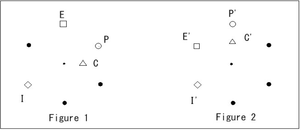
In the experiment, the locations of four invariant features (cycles, isolated points, endpoints and maximum degree points) were taken as target superficial features. Among other invariant features, these features were considered to be visibly conspicuous and conceptually easily understandable. The locations of these invariants were determined by polar coordinates. Here, a cycle is defined as a closed alternating sequence of points and line segments, beginning and ending with the same point. The degree of a point is defined as the number of line segments incident with the point. Hence, a point whose degree is zero is called an isolated point; a point whose degree is one is called an endpoint; and a point whose degree is the largest among all of the points is called a maximum degree point (see more in [30]). For a graphical explanation of the four invariant features, see Figure 2.
If two or more discrete locations of a figure share the same invariant feature value, the locations are represented by their centroid. By the same token, the location of a cycle is defined as the centroid of all of the line segments constituting the cycle. Here, a centroid was expressed by the respective means of the values of the x and y coordinates of the points or the line segments concerned.
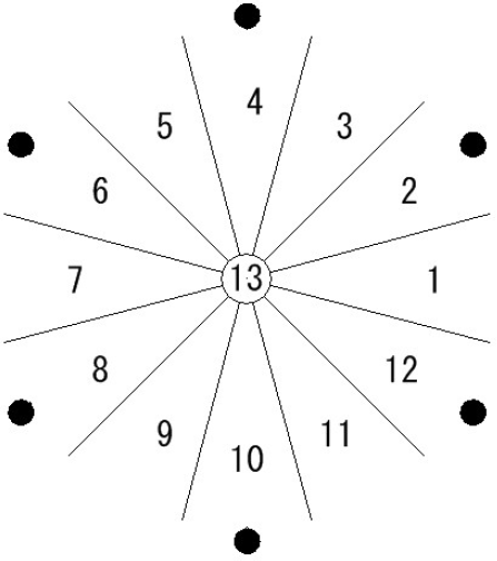
For the purpose of this study, how the shifts of invariant feature locations from one figure to another should be defined has critical importance. Here, a shift of location of an invariant feature was expressed as an angular distance from the location of the feature in one figure to the corresponding location of the same feature in another figure in counterclockwise direction (Figure 3). In addition, the location of an invariant feature was expressed by a label that represented one of 13 regions (Figure 4).
In my previous study on mental rotation [36], I tried to investigate whether mental rotation occurred for the identification of disoriented figures. Stimulus pairs were classified into two categories: same pairs and different pairs. The classification was solely made by the superficial shapes of a pair of figures. In the present experiment, stimulus pairs were classified according to the shifting patterns of invariant feature locations between the two figures of pairs, which could shed light on the relationship between the detection of deeper structural features and their more superficial transformation for the recognition of figures.
2. Methods
2.1. Stimuli
In this study, I used (6, 5) figures as stimuli, because the total number of figures is fairly large (i.e., 3003 figures). All (6, 5) figures are classified into 15 isomorphic sets. Using unfamiliar (6, 5) figures avoids the confusion of memorization procedures, which may have played a role in many previous mental rotation studies.
A pair of (6, 5) figures were simultaneously presented on a 17-inch LCD monitor (NEC AS171MC) controlled by an NEC MJ33AA-9 microcomputer. The shortest line segment lengths of a figure were 3.8 cm and the longest segments were 7.6 cm, with visual angles of 3.34° and 6.69°, respectively. Points with a diameter of 0.4 cm were also displayed on the monitor, and the locations of their centers were shifted 0.2 cm out of the vertices of invisible regular hexagons. The two figures in a stimulus pair were simultaneously presented at horizontally parallel positions, with a distance of 9.4 cm between the centers of the figures.
2.1.1. Stimulus Selection
In order not to be confounded by invariant feature differences, all pairs of stimuli were designed to be mutually isomorphic.
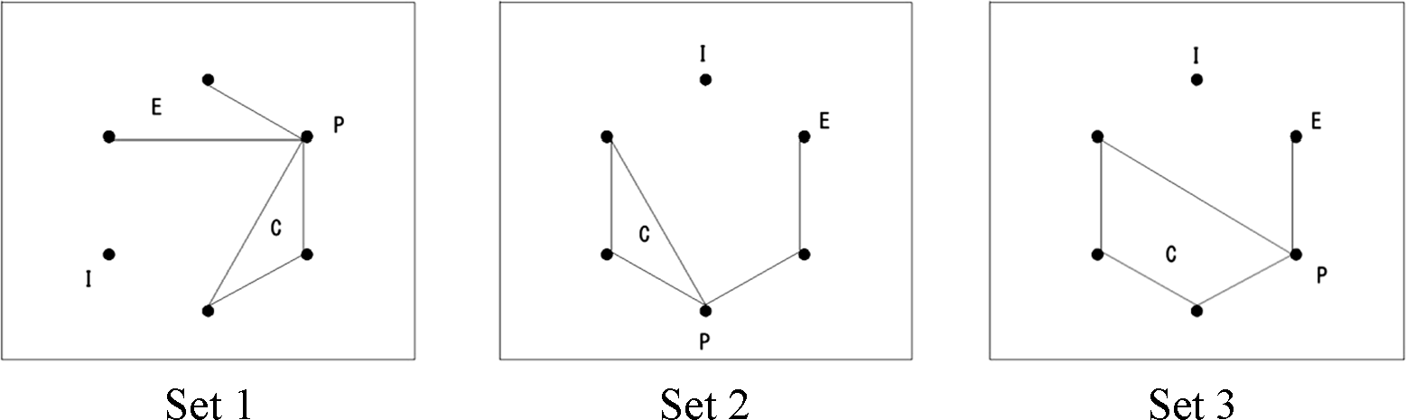
The experiment adopted the following criteria to choose appropriate isomorphic sets as stimuli: (1) the size of the sets should be large (≥50); (2) if two or more target feature locations take the same location in the figures of an isomorphic set, the set should be discarded; and (3) if a target feature location is indefinable in the figures of an isomorphic set (i.e., if an invariant feature does not exist, its location is indefinable), the set should be discarded. Based on these conditions, three isomorphic sets were chosen. Although the presence of intersections of line segments is not an invariant feature (i.e., not a graph invariant), Wolfe and DiMase [37] claimed that intersections can be detected preattentively. To avoid the possible confusion between the effect of intersections and the effect of invariant features, I added the condition that figures with intersections of line segments should be excluded as stimuli. The examples in Figure 5 illustrate how these conditions were implemented. The figure of Set 1 represents the isomorphic set with 90 figures after excluding those with line intersections. The size of Set 2 is 120 after excluding figures with intersections. The size Set 3 is 60 after excluding figures with intersections.
2.1.2. Generation of Stimulus Pairs
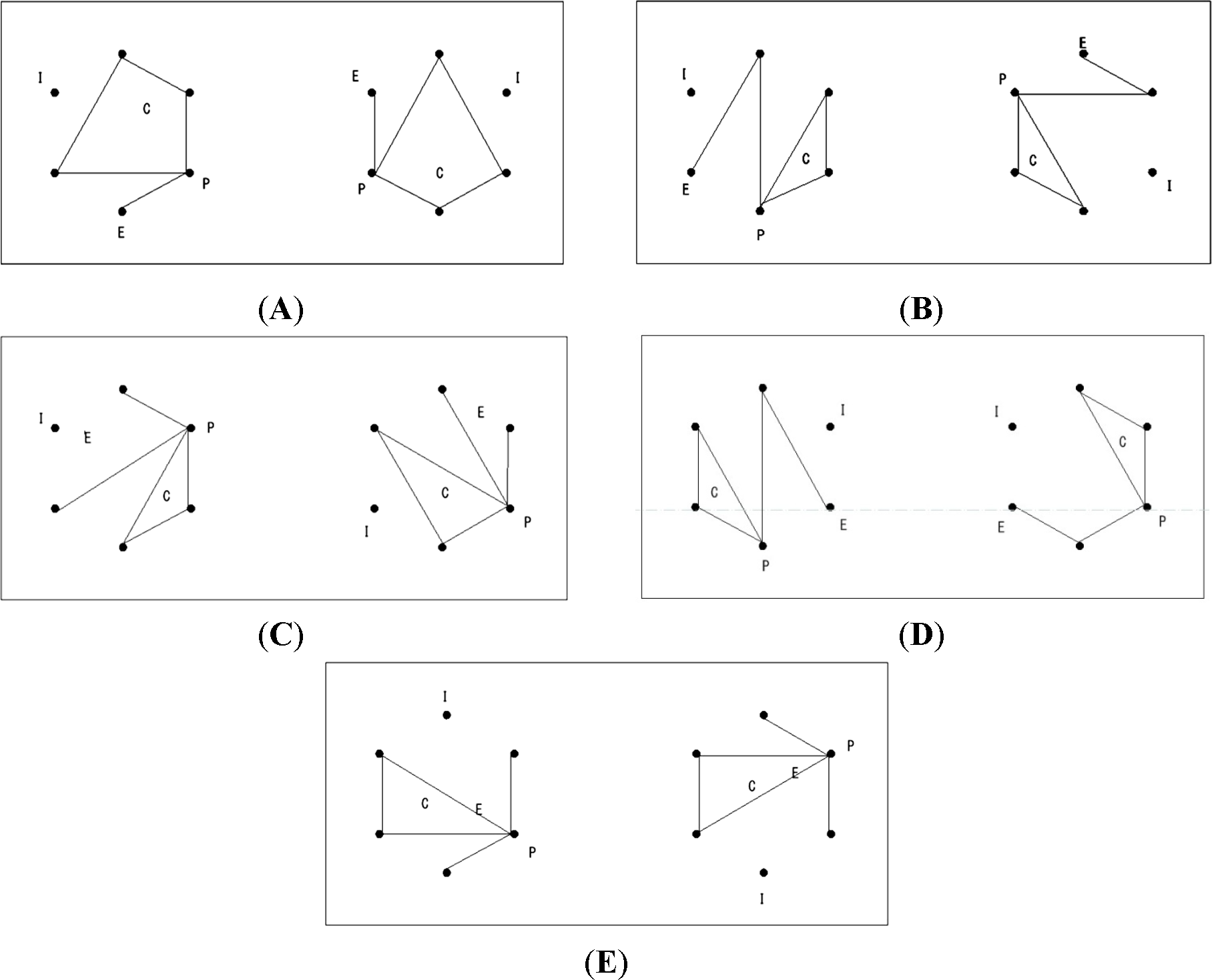
For each participant, five types of figure pairs were randomly generated. Firstly, an identical (Id) pair, in which two figures of a pair were the same shape, but differently oriented, with their angular distance 60°, 120°, 180°, 240° or 300°. For Id pairs, the shifts of the four invariant features are always the same. Secondly, non-identical (Nonid) pairs, in which two figures had different shapes. Nonid pairs were further classified according to the consistency in the shifts of locations among the four invariant features. A Nonid 1/4 pair consisted of two figures in which one of four locational shifts was different from the other three identical shifts. A Nonid 2/4 pair consisted of two figures whose two shifts were different from the other two identical shifts. A Nonid 4/4 pair consisted of two figures whose four shifts were mutually different from each other. Within Nonid 1/4, 2/4 and 4/4 pairs, the pairs whose respective figures were mutually axisymmetric were excluded as stimuli. Finally, there was a non-identical and axisymmetric (or Ax) pair, in which the shapes of two figures were axisymmetric about one of the six axes that pass through the center of the invisible hexagon (i.e., 0°, 30°, 60°, 90°, 120° or 150° from the horizontal). Of the Ax pairs, only pairs of figures in which two shifts were different from the other two identical shifts (i.e., Ax 2/4) were chosen as stimuli. If the two respective regions of an invariant feature of a pair happened to be 13, their shift was defined as 0. If the region of an invariant feature of a figure was 13 and the region of the corresponding feature of the other figure was not 13, the pair was discarded from the stimulus set. Therefore, five types of stimulus pairs were generated: Id 0/4, Nonid 1/4, Nonid 2/4, Nonid 4/4 and Ax 2/4 pairs. Figure 6 illustrates examples of these five pair types.
Pairs were generated for test trials as follows: (1) Out of a total 3003 (6, 5) figures, only those that had no intersections of lines and belonged to the isomorphic Set 1, Set 2 or Set 3 were selected and separately pooled according to the sets. (2) Within each isomorphic pool, all combinations of mutually different figures were examined to determine whether the locational regions of each invariant feature between the two figures were valid (i.e., both were = 13 or both were ≠ 13). If they were all valid, the shifts of the four locations were calculated and were further classified according to their unity (i.e., 0/4, 1/4, 2/4 and 4/4). (3) Pairs of figures that could be matched in shape at one of the five angular distances were accumulated in the Id 0/4 pool. (4) Pairs that were not axisymmetric were separately accumulated in Nonid 1/4, Nonid 2/4 and Nonid 4/4 pools, accordingly. (5) The 2/4 pairs that were axisymmetric about one of the six axes were accumulated in the Ax 2/4 pool. (6) The five pools of pairs belonging to an isomorphic set were respectively concatenated with those of other isomorphic sets. (7) From the concatenated Id 0/4 pool, 128 pairs were randomly selected. From the concatenated Nonid 1/4, Nonid 2/4, Nonid 4/4 and Ax 2/4 pools, 32 pairs from each were randomly selected. These formed a total of 256 test pairs. (8) The concatenated pools selected for the tests were each split into two halves, which formed two subsets of test pairs. (9) Within each subset of test pairs, the order of the presentations was randomized. Likewise, two practice subsets were randomly ordered and each included three Id 0/4 pairs, one Nonid 1/4, one Nonid (2/4) and one Nonid (4/4) pair. Therefore, the proportion of the numbers of test pairs included in Id 0/4, Nonid 1/4, Nonid 2/4, Nonid 4/4 and Ax 2/4 was 4:1:1:1:1, respectively.
2.1.3. Procedure
Three buttons (labeled “Enter”, “F6” and “F5”) were horizontally aligned from left to right on a switch box. Participants were instructed to respond by pushing either the “F6” or “F5” button on the switch box. The response speed of the monitor was 5 ms, and the time was measured to the nearest 1 ms. Each participant sat in front of the monitor with his/her head placed on a chin-rest, 60 cm from the screen. The start of a trial was indicated by a “ready” message on the screen. When a participant pushed the “Enter” button, the message cleared and a blank screen was shown for 2.5 s. A fixation cross then appeared at the center of the display for 0.5 s, accompanied by a beep. The fixation cross was subsequently replaced by two stimulus figures, constituting a pair.
Participants were asked to judge whether a presented pair of figures were the same or different in shape, irrespective of their orientations. Participants were instructed to use the index finger of their right hand to push the “F6” button and the middle finger of their right hand to push the “F5” button. The stimulus figures were kept on the screen until the participant responded. Emphasis was placed on both speed and accuracy. A sequence that started from a push of “Enter” to a push of either “F5” or “F6” was designated as a trial. Trials were divided into two blocks according to the function assigned to the “F5” and “F6” buttons, and the functions of the buttons alternated across the blocks. This alternation of the button functions counterbalanced possible judgment time differences caused by the different fingers. A block of trials consisted of six practice trials and 128 test trials using pairs of figures generated in the manner depicted in Section 2.1.2.
At the start of each block, a participant was instructed as to which button to press to indicate “same” or “different”. The assignment of the button functions at the first block was randomized for each participant. No hint was given as to the nature of the types of pairs. Participants received immediate feedback concerning the correctness of their responses in the practice trials, but received no feedback in the test trials. Response latency was defined as the time elapsed from the presentation of a pair of stimuli to a participant’s response.
2.2. Participants
Six male and 14 female university students, aged 20–23 years, voluntarily participated in the experiment. All participants had normal or corrected-to-normal vision.
2.3. Ethics
The study was approved by the Hakuoh University Ethics Committee on November 19, 2012.
3. Results
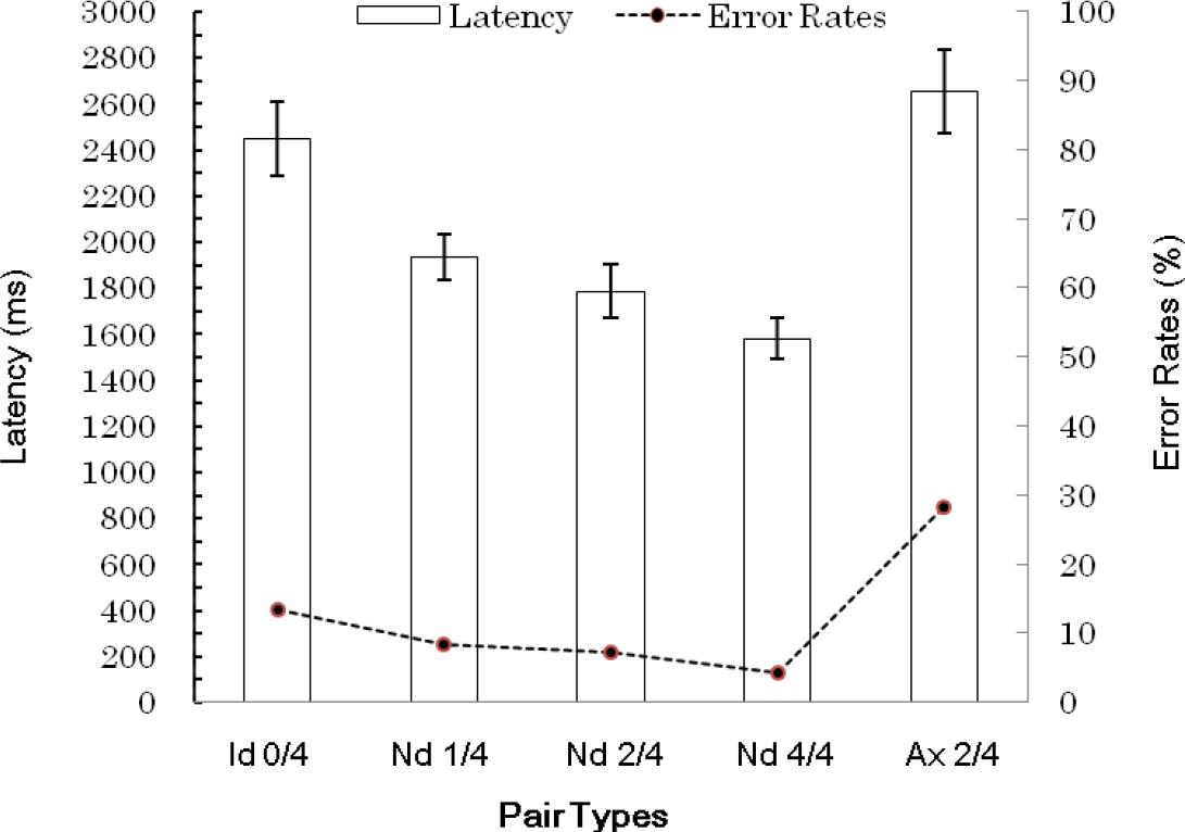
Data were excluded from analysis for one participant who made erroneous judgments to all of the presented Ax 2/4 pairs. Figure 7 shows the mean latencies and the error rates in the judgments of each pair type.
An analysis of variance (ANOVA) on the arcsine-transformed error rates showed that the effect of pair types was significant (F (4, 72) = 9.6, p < 0.001). Multiple comparisons between each pair type indicated that the error rates were significantly different between Id 0/4 and Nonid 1/4 pairs, Id 0/4 and Nonid 2/4 pairs, Id 0/4 and Nonid 4/4 pairs, Nonid 1/4 and Ax 2/4 pairs, Nonid 2/4 and Ax 2/4 pairs and Nonid 4/4 and Ax 2/4 pairs (p < 0.05).
The latencies of only correct responses were analyzed. Latencies were explored with an ANOVA analysis, revealing a significant effect of pair type (F (4, 72) = 47.3, p < 0.001). Comparisons of each combination of pairs revealed that mean latencies were significantly different between any combination of pairs (p < 0.05), with the increasing latencies as follows: Nonid 4/4, Nonid 2/4, Nonid 1/4, Id 0/4 and Ax 2/4. As the error rates and the latencies both indicated the same trend, it appears that there is no trade-off between speed and accuracy.
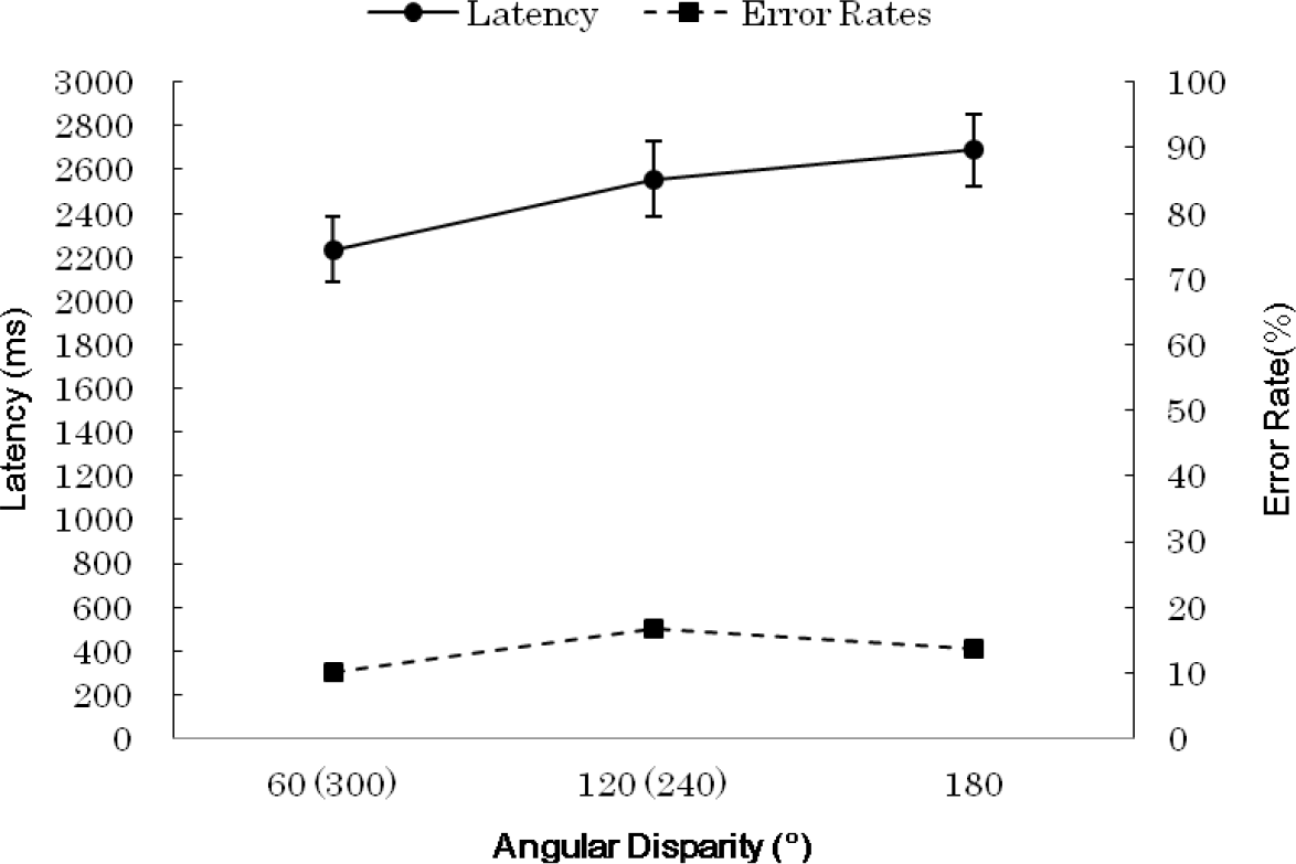
A linear regression analysis was applied to the average latencies of Id 0/4 pairs against the angular distances of the respective participants with clockwise and counterclockwise directions combined (Figure 8). That is, except the latency at 180°, the value at 60° was represented by the averaged latencies at 60° and 300°, and the value at 120° was represented by the averaged latencies at 120° and 240°. The analysis indicated that the linear regression was significant (b = 3.90, F (1. 93) = 5.57, p = 0.020).
The angular distance of the orientations of two figures is calculable when their respective principal axes can be determined or when two figures have the same shape. However, as the figures of Nonid pairs do not satisfy these conditions, linear regression analyses could not be applied to Nonid pairs.
4. Discussion
The significant linear relationship between the latencies and the angular distances suggests that mental rotation processing was applied to Id pairs. This result seemed to contradict the result of Kanbe [36] in which mental rotation was considered not to have occurred. It was inferred in the earlier study that the absence of mental rotation would be ascribed to a small number of Ax pairs in Nonid pairs. This inference seems not to be consistent with the present result, which suggested the occurrence of mental rotation in spite of a relatively small proportion of Ax pairs (25%) in “different pairs” (i.e., Nonid pairs and Ax pairs combined). This inconsistency could be derived from the different rules employed to generate Nonid pairs. In the earlier study, Nonid pairs consisted of any pairs that were not identical in shape and, thus, could include many non-isomorphic pairs, which were found to be easily discriminated [29]. On the other hand, in the present study, all Nonid pairs were mutually isomorphic and, thus, were harder to discriminate. In this respect, it is considerable that an effortful and time-consuming mental rotation had to be summoned to distinguish Id pairs from hard to discriminate Nonid pairs.
Latencies were shortest in Nonid 4/4 pairs, next shortest in Nonid 2/4 pairs and longest in Nonid 1/4 pairs, which would strongly indicate that the shifts in the locations of the four arbitrarily-chosen invariant features were in fact used for the rejection of identities of Nonid pairs. More specifically, participants would calculate the shift of the location of a feature from one figure to the other and compare the shift with previously calculated shifts one feature at a time. If they detected a difference in the shifts of one feature from another, they would terminate the comparisons and decide that the two figures were different.
If the shifts of the locations of the four features are compared all at one time, the distinction of the two figures after the comparison can be made without any latency difference among Nonid pairs. If the comparison includes the shifts of two or three invariant feature locations at a time, the smaller latencies for Nonid 4/4 than for Nonid 2/4 pairs, as well as for Nonid 2/4 than for Nonid 1/4 pairs would not be expected. Longer latencies for Id 0/4 pairs than for Nonid 1/4 pairs were also consistent with the explanation based on such sequential, self-terminating comparisons. It assumes that if participants fail to detect a difference in the shifts of the locations within a pre-specified number of feature comparisons (presumably including the four features employed in the study), they would decide the two figures of a pair were the same in shape.
However, longer latencies for Ax 2/4 pairs than for Nonid 2/4 pairs were not consistent with the sequential, self-terminating comparison of locational shifts. If participants in fact compared the shifts in such a manner, they should have decided Ax 2/4 pairs to be different in shape as quickly and as accurately as they decided Nonid 2/4 pairs to be different. Furthermore, the error rate for Ax 2/4 pairs was significantly higher than those of Nonid pairs and was marginally higher than the rate for Id 0/4 pairs (p = 0.052), replicating my previous results [35]. Combined with the longest latencies in Ax 2/4 pairs, it seems obvious that Ax pairs were difficult to discriminate from Id pairs, and even the shifting pattern was equalized. Therefore, the hypothesis that the difficult discriminability of Ax pairs should be derived from the failure to detect a disruption of the unisonous shifts was not supported.
Although we must be cautious that putting too much emphasis on the theoretical difference between the positions of invariant feature processing and of analog holistic processing would be misleading [36,38], the results could be interpreted as mental rotation would be applied to Id pairs and feature comparison processing would be applied to Nonid pairs. At the same time, it would be worth considering the possibility in future studies that feature comparisons and mental rotation constitute a continuum for the processing of figural recognition in general. In spite of violating the holistic analog position, provided that rotating (or calculating) one location of an invariant feature to the other location should require a longer time with the increase of their angular distance, a phenomenal linear relationship between the latencies and the angular distances would manifest itself in Id pairs.
Then, what aspects of Ax pairs are different from those of Nonid pairs, both of which have the same shifting pattern? For an Ax pair, a specific feature is located on the left-hand side in one figure and on the right-hand side in the other figure about an externally-specified axis of symmetry, whereas for Nonid, pairs there is no such constraint on their locations. Such information, which can be specified in reference to an axis, could be called handedness [13]. In addition, the parity of the lengths of line segments is preserved between the right-handed configurations about an axis of symmetry in one figure and the left-handed configurations about the axis in the other figure. As for the shifting pattern, a feature location in the right-handed configuration and the location of a different feature in the left-handed configuration of Ax pairs will shift in opposite directions (i.e., clockwise and counter-clockwise directions) from one figure to the other. In this respect, the handedness information in reference to a specific axis, the lengths of line segments and the direction of locational shifts are all superficial properties not under control in the present experiment.
If people are in fact not very sensitive to handedness information, it would either imply that the comparisons of individual locational shifts are ineffectively executed or that people lack the ability to discriminate handedness as a whole. If the latter is the case, a holistic transformational process, like mental rotation, should be induced. On the other hand, if individual comparisons of the locational shifts are executed for Ax pairs, the discrimination difficulty could be derived from the confusion of the comparisons by the change of directions of locational shifts [29]. The efficient responses for Nonid pairs and the inefficient responses for Ax pairs would be explainable by the comparisons of locational shift position, but would not be by the holistic transformation position, unless some additional assumption is induced. One such possibility is that a change of processing strategies from the feature comparison processing to holistic transformation processing occurs at some point.
The total length of line segments of a given figure [29] can discriminate some Nonid pairs of figures from Id pairs. However, this cannot discriminate Ax pairs from Id pairs, because every line segment of a figure has an equal length counterpart segment in the other figure about an axis of symmetry in the Ax pair. The use of total line length could therefore be effective as a first approximation to reject identities for Nonid pairs, prior to the application of holistic transformational processing.
In the future, it would be worthwhile to examine whether same handed figure pairs, in which a specific invariant feature is located to the same side in reference to a corresponding axis in both figures of a pair, would bring about shorter latencies in decision making than differently handed pairs, in which a specific feature is located on different sides about a corresponding axis in the two figures. If this occurs, it would suggest the presence of sensitivity to handedness information.
In conclusion, the latencies obtained for Nonid pairs decreased with the increase of the difference in the shifts of feature locations, indicating that serial, self-terminating comparisons of the shifts were applied to the discrimination of Nonid pairs from Id pairs. However, the longer latencies in Ax 2/4 pairs than in Nonid 2/4 pairs suggested that the difficulty for axisymmetric pairs of figures was not caused by the complex shifting patterns, and thus, the difficulty was not satisfactorily explained by the comparisons of feature locations.
Acknowledgments
This research was supported by an annual personal research fund granted by Hakuoh University.
Conflicts of Interest
The author declares no conflict of interests.
References
- Shepard, R.N.; Metzler, J. Mental rotation of three-dimensional objects. Science 1971, 171, 701–703. [Google Scholar]
- Johnson-Laird, P.N. Mental Models: Toward a Cognitive Science of Language, Inference, and Consciousness; Cambridge University Press: Cambridge, UK, 1983. [Google Scholar]
- Pylyshyn, Z.W. The rate of “mental rotation” of images: A test of a holistic analogue hypothesis. Mem. Cognit. 1979, 7, 19–28. [Google Scholar]
- Cooper, L.A. Mental rotation of random two-dimensional shapes. Cognit. Psychol. 1975, 7, 20–43. [Google Scholar]
- Cooper, L.A.; Podgorny, P. Mental transformations and visual comparison processes: Effects of complexity and similarity. J. Exp. Psychol. Hum. Percept. Perform. 1976, 2, 503–514. [Google Scholar]
- Yuille, J.C.; Steiger, J.H. Nonholistic processing in mental rotation: Some suggestive evidence. Percept. Psychophys. 1982, 31, 201–209. [Google Scholar]
- Steiger, J.H.; Yuille, J.C. Long-term memory and mental rotation. Can. J. Psychol. 1983, 37, 367–389. [Google Scholar]
- Bethell-Fox, C.E.; Shepard, R.N. Mental rotation: Effects of stimulus complexity and familiarity. J. Exp. Psychol. Hum. Percept. Perform. 1988, 14, 12–23. [Google Scholar]
- Hochberg, J.; Gellman, L. The effect of landmark features on mental rotation times. Mem. Cognit. 1977, 5, 23–26. [Google Scholar]
- Larsen, A. Pattern matching: Effects of size, ratio, angular difference in orientation, and familiarity. Percept. Psychophys. 1985, 38, 63–68. [Google Scholar]
- Folk, M.D.; Luce, R.D. Effects of stimulus complexity on mental rotation rate of polygons. J. Exp. Psychol. Hum. Percept. Perform. 1987, 13, 395–404. [Google Scholar]
- Bauer, B.; Jolicoeur, P. Stimulus dimensionality effects in mental rotation. J. Exp. Psychol. Hum. Percept. Perform. 1996, 22, 82–94. [Google Scholar]
- Cohen, D.; Kubovy, M. Mental rotation, mental representation, and flat slopes. Cognit. Psychol. 1993, 25, 351–382. [Google Scholar]
- Corballis, M.C.; Zbrodoff, N.J.; Shetzer, L.I.; Butler, P.B. Decisions about identity and orientation of rotated letters and digits. Mem. Cognit. 1978, 6, 98–107. [Google Scholar]
- Corballis, M.C.; Nagourney, B.A. Latency to categorize disoriented alphanumeric characters as letters or digits. Can. J. Psychol. 1978, 32, 186–188. [Google Scholar]
- Jolicoeur, P. The time to name disoriented natural objects. Mem. Cognit. 1985, 13, 289–303. [Google Scholar]
- McMullen, P.A.; Jolicoeur, P. Reference frame and effects of orientation on finding the tops of rotated objects. J. Exp. Psychol. Hum. Percept. Perform. 1992, 18, 807–820. [Google Scholar]
- Parsons, L.M. Visual discrimination of abstract mirror-reflected three-dimensional objects at many orientations. Percept. Psychophys. 1987, 42, 49–59. [Google Scholar]
- Just, M.A.; Carpenter, P.A. Cognitive coordinate systems: Accounts of mental rotation and individual differences in spatial ability. Psychol. Rev. 1985, 92, 137–172. [Google Scholar]
- Bedford, F.L. Toward a general law of numerical/object identity. Curr. Psychol. Cognit. 2001, 20, 113–175. [Google Scholar]
- Wagemans, J.; Van Gool, L.; Lamote, C; Foster, D.H. Minimal information to determine affine shape equivalence. J. Exp Psychol. Hum. Percept. Perform. 2000, 26, 443–468. [Google Scholar]
- Wagemans, J.; Lamote, C.; van Gool, L. Shape equivalence under perspective and projective transformations. Psychon. Bull. Rev. 1997, 4, 248–253. [Google Scholar]
- Chen, L. Topological structure in visual perception. Science 1982, 218, 699–700. [Google Scholar]
- Chen, L. Topological structure in the perception of apparent motion. Perception 1985, 14, 197–208. [Google Scholar]
- Todd, J.T.; Chen, L.; Norman, J.F. On the relative salience of Euclidean, affine, and topological structure for 3-D form discrimination. Perception 1998, 27, 273–282. [Google Scholar]
- Hecht, H.; Bader, H. Perceiving topological structure of 2-D patterns. Acta Psychol. 1998, 99, 255–292. [Google Scholar]
- Chen, L.; Zhou, W. Holes in illusory conjunctions. Psychon. Bull. Rev. 1997, 4, 507–511. [Google Scholar]
- Zhang, J.; Zhu, W.; Ding, X.; Zhou, C.; Hu, X.; Ma, Y. Different masking effects on “hole” and “no-hole” figures. J. Vis. 2009, 9(6), 1–14. [Google Scholar]
- Kanbe, F. On the generality of the topological theory of visual shape perception. Perception 2013, 42, 849–872. [Google Scholar]
- Harary, F. Graph Theory; Addison-Wesley: Boston, MA, 1969. [Google Scholar]
- Corballis, M.C.; Cullen, S. Decisions about the axes of disoriented shapes. Mem. Cognit. 1986, 14, 27–38. [Google Scholar]
- Corballis, M.C. Recognition of disoriented shapes. Psychol. Rev. 1988, 95, 115–123. [Google Scholar]
- Takano, Y. Perception of rotated forms: A theory of information types. Cognit. Psychol. 1989, 21, 1–59. [Google Scholar]
- Förster, B.; Gebhardt, R.; Lindlar, K.; Siemann, M.; Delius, J.D. Mental-rotation effect: A function of elementary stimulus discriminability? Perception 1996, 25, 1301–1316. [Google Scholar]
- Kanbe, F. Role of axisymmetry in mental rotation. P. Jpn. Psychol. Assoc. 2002, 25–27, 568, In Japanese. [Google Scholar]
- Kanbe, F. Mental rotation of random lined figures. Jpn. Psychol. Res. 2001, 43, 141–147. [Google Scholar]
- Wolfe, J.M.; DiMase, J.S. Do intersections serve as basic features in visual search? Perception 2003, 32, 645–656. [Google Scholar]
- Vanrie, J.; Willems, B.; Wagemans, J. Multiple routes to object matching from different viewpoints: Mental rotation versus invariant features. Perception 2001, 30, 1047–1056. [Google Scholar]


© 2015 by the authors; licensee MDPI, Basel, Switzerland This article is an open access article distributed under the terms and conditions of the Creative Commons Attribution license (http://creativecommons.org/licenses/by/4.0/).
Share and Cite
Kanbe, F. Can the Comparisons of Feature Locations Explain the Difficulty in Discriminating Mirror-Reflected Pairs of Geometrical Figures from Disoriented Identical Pairs? Symmetry 2015, 7, 89-104. https://doi.org/10.3390/sym7010089
Kanbe F. Can the Comparisons of Feature Locations Explain the Difficulty in Discriminating Mirror-Reflected Pairs of Geometrical Figures from Disoriented Identical Pairs? Symmetry. 2015; 7(1):89-104. https://doi.org/10.3390/sym7010089
Chicago/Turabian StyleKanbe, Fumio. 2015. "Can the Comparisons of Feature Locations Explain the Difficulty in Discriminating Mirror-Reflected Pairs of Geometrical Figures from Disoriented Identical Pairs?" Symmetry 7, no. 1: 89-104. https://doi.org/10.3390/sym7010089