Precoding Design and Power Allocation in Two-User MU-MIMO Wireless Ad Hoc Networks

Information Engineering School, Nanchang University, Nanchang 330031, China
*
Author to whom correspondence should be addressed.
Symmetry 2017, 9(11), 247; https://doi.org/10.3390/sym9110247
Submission received: 22 September 2017
/
Revised: 17 October 2017
/
Accepted: 19 October 2017
/
Published: 25 October 2017
Abstract
:In this paper, we consider the precoding design and power allocation problem for multi-user multiple-input multiple-output (MU-MIMO) wireless ad hoc networks. In the first timeslot, the source node (SN) transmits energy and information to a relay node (RN) simultaneously within the simultaneous wireless information and power transfer (SWIPT) framework. Then, in the second timeslot, based on the decoder and the forwarding (DF) protocol, after reassembling the received signal and its own signal, the RN forwards the information to the main user (U1) and simultaneously sends its own information to the secondary user (U2). In this paper, when the transmission rate of the U1 is restricted, the precoding, beamforming, and power splitting (PS) transmission ratio are jointly considered to maximize the transmission rate of U2. To maximize the system rate, we design an optimal beamforming matrix and solve the optimization problem by semi-definite relaxation (SDR), considering the high complexity of implementing the optimal solution. Two sub-optimal precoding programs are also discussed: singular value decomposition and block diagonalization. Finally, the performance of the optimization and sub-optimization schemes are compared using a simulation.
1. Introduction
Recently, energy harvesting (EH) has received widespread attention as a promising technology capable of overcoming the problem of energy shortages in wireless communication networks [1]. Many energy harvesting models have been proposed in [2,3]. In particular, [4] studies a time allocation scheme to strike a balance between wireless power transfer and information transfer. These models demonstrate that wireless communication systems can effectively support EH [5,6]. Since radio frequency (RF) signals can transmit information and energy simultaneously, a joint investigation of SWIPT has recently drawn significant attention [7], and various models for different SWIPT systems have been considered to characterize the performance trade-off between wireless energy transfer (WET) and wireless information transfer (WIT) in the same transmitted signal [8,9,10]. Furthermore, one key issue in implementing SWIPT is the practical limitation that existing energy harvesting circuits cannot be used to decode and harvest the RF signals concurrently [11], to solve this problem, PS designs have been proposed for SWIPT, with PS, the received signal is split into two parts, with one part used for ID and the other part for EH [12].
Although EH can solve the problem of energy shortages in wireless networks, when numerous devices are connected to the network, the available spectrum will be seriously inadequate, Furthermore, signal coverage is also a problem in remote areas. These problems are expected to be solved using MIMO technology [13], which can effectively increase data throughput and extend system transmission distance without requiring additional bandwidth or increasing the total transmission power consumption [14].
To significantly improve spectrum utilization in MIMO networks, cognitive radio has been widely considered by previous studies [15,16], in which [15] considered a linear precoder design for an underlay cognitive radio MIMO broadcast channel and [16] considered the power allocation for spectrum sharing in cognitive radio networks.
The two basic features of MIMO wireless propagation channels are broadcasting and multiple-access [17]. Therefore, signals transmitted on a certain link can be detected by other neighboring nodes in the wireless network. Those nodes can form an ad hoc network and serve as relays that help forward the message to the receiving terminal. In addition, although MU-MIMO has been used in ad hoc networks to improve system performance (e.g., in [18] for capacity enhancement and in [19] for stream control), using a precoding design and power allocation in MU-MIMO ad hoc networks to improve throughput has not been considered in previous works. Moreover, using a SWIPT MIMO strategy with relays can effectively improve the transmission rate, and the communication quality is determined by the RF energy receiver structure and the precoding performance. However, neither the singular value decomposition (SVD) algorithm nor the block diagonalization (BD) algorithms adopted in the precoding design of previous SWIPT MIMO cooperative systems have yet been considered.
Motivated by the aforementioned problem, to further improve the throughput of a SWIPT MIMO cooperative system, this paper studies a two-user MIMO system in a wireless ad hoc network (WAHN). First, by using a PS receiver under the DF protocol, relay transmission beamforming, and power splitting are analyzed. Then, under the premise of satisfying the quality of service of the main users, power allocation and an optimal precoding design are conducted jointly to maximize the transmission rate of the secondary users. Finally, to compare the performance, two sub-optimal precoding methods are designed. The optimal solution is found by applying semi-definite relaxation (SDR) techniques; it is proven that a rank-one optimal solution always exists. Furthermore, Karush-Kuhn-Tucker (KKT) conditions are also applied to solve the problem.
The remainder of this paper is organized as follows: Section 2 introduces the system model and presents the problem formulation. In Section 3, the SDR algorithm is adopted to derive the optimal solution, and we prove that an optimal solution is feasible. Based on the SVD and BD algorithms, Section 4 presents two sub-optimal solutions for the first and second timeslots, respectively. Section 5 presents numerical results to compare the performance of various approaches, and Section 6 concludes the paper.
2. System Model and Problem Formulation
As shown in Figure 1, this paper considers a two-user MIMO wireless ad hoc network that consists of one source node, one relay node, and two user terminal nodes (denoted by U1 and U2, respectively). We assume that the source node (SN) and the relay node (RN) are both equipped with transmitting antennas and that the SN has a stable energy supply, whereas the RN must replenish its energy from the received signals broadcast by the SN in the first timeslot. This energy is then stored and used to forward the information from the SN to the main user, U1, and to transmit its own information to the secondary user, U2, in the second timeslot. The users’ terminals are both equipped with receiving antennas.
In this paper, the SN is considered to improve the efficiency of information and energy transmission through a precoding design, and the precoding design at the RN is used to ensure that the receiving user can efficiently decode the received signal.
In the first phase (timeslot 1), assume that the EH and information decoding (ID) receivers are co-located in the RN, the channel state information between the SN and the RN is perfectly known, and the channel matrix is denoted as . The energy receiver of the relay node does not need to collect energy by switching the signal from the RF band to the baseband. Furthermore, based on the principle of energy conservation, P denotes the total RF-band power (energy normalized by the baseband symbol period) harvested from the receiver’s receiving antennas. It is worth noting that P is proportional to the received baseband signal:
where denotes the energy conversion efficiency. For convenience, in this paper, unless stated otherwise, it is assumed that .
Then, the received signals at the RN can be expressed as follows:
where denotes the channel coefficients from the SN to the RN, and denotes the relay noise vector. It is assumed that are independent overall and that . The covariance matrix of is denoted by , the power constraint in the source terminal is denoted by , is the signal power splitting ratio for the ID phase, and the ratio of the EH phase can be expressed as . Thus, the transmission rate can be expressed as follows:
The second phase requires harvesting more energy to ensure continued information transmission. If the threshold of the rate is satisfied, the remaining power will all be used to harvest energy. The energy harvested by the RN can be expressed as:
where , , and is the minimum transmission rate that the SN requires.
In the first timeslot, under the premise of satisfying the SN rate requirement, maximizing the energy received by the RN can allow it to transmit more information in the second timeslot, thus achieving the goal of maximizing system throughput. Then, the optimal problem in the first phase of the PS scheme based on a cooperative network can be formulated as follows:
It is assumed that the relay is capable of decoding the source signal and forwarding it appropriately. In the second phase, the relay simultaneously transmits signals to U1 and U2. The relay node will decode the signal and reconstruct the message. The RN transmission signal consists of two parts: the signal revived from the SN is , and the RN’s independent signal is . Then, the signal vector received at U1 is:
and the signal vector received at U2 is:
where and denote the channel coefficients between the RN and U1 and U2, respectively. The RN uses the pre-decoding vector to forward the signal from the SN and the pre-decoding vector to transmit its own signal. The additional Gaussian noise at the destination terminal is , .
Accordingly, the signal-to-interference plus the noise ratio (SINR) of U1 can be expressed as follows:
and the SINR of U2 can be expressed as:
In the next section, this paper will investigate the optimal precoding vectors and to eliminate the interference in the signal between two users and maximize the transmission rate.
Since the RN forwards the SN’s signal based on the DF protocol, as was concluded in [14], the most effective condition is achieved when the transmission rate from the SN to the RN in the first timeslot is equal to the transmission rate of the RN to U1 in the second timeslot. Thus, in the second timeslot, the optimal target is to maximize the rate of U2 while still ensuring the required minimum rate of U1. Consequently, the optimization problem can be formulated as follows:
where denotes the required minimum rate of U1.
3. Feasibility Proof and Optimal Solution
The optimization problem in the first timeslot is similar to that in traditional SWIPT and has been widely shown to be feasible [20]; therefore, this section focuses on the feasibility of the optimization problem P2 in the second timeslot.
3.1. A Feasibility Analysis of Problem P2
To prove the feasibility of problem P2, first, the SINR of U2 is set to zero (): the relay forwards only the SN’s information and does not transmit its own signal. In this case, problem P2 is transformed into a typical single-user MIMO system relay node problem, which has been solved in many studies [21]. Based on the DF protocol, the maximum transmission rate can be achieved when the SINR is met in the first timeslot (). Thus, P2 can be reformulated as follows:
where is the only variable in Equation (11). By setting , and applying semi-definite planning (SDP) in P2-A, P2-A can be expressed as:
If for P2-A-SDP, there exists an optimal solution , then the optimal solution for problem P2-A can be obtained by eigenvalue decomposition (EVD). Since problem P2-A-SDP is a convex problem, it can be solved via existing software (e.g., Matlab CVX developed by MathWorks, Natick, MA, USA [22,23]).
Since problem P2-A is feasible, and problem P2 is similar to problem P2-A, P2 is also a feasible problem.
Next, the optimization algorithms for problems P1 and P2 are described.
3.2. The Optimization Algorithm for Problem P1
The optimization goal of problem P1 is to maximize a concave function, and the function in P1’s constraint is a convex function; therefore, P1 is a typical convex optimization problem [11]. In the first phase, P1 is non-convex in its initial form because both the object function and the subject function involve coupled and . This problem can be solved via a two-step procedure. First, fix through a simple one-dimension search over . Then, P1 can be re-described as follows:
After transforming P1 into a convex problem with only one unknown dimension, it can be solved by existing solvers, such as Matlab CVX [22]. An one-dimensional search is performed on , and the optimal precoding matrix is obtained using the CVX toolbox. At that point, the corresponding to the optimal precoding matrix is the optimal power allocation factor.
3.3. The Optimization Algorithm for Problem P2
Applying beamforming (BF) to the MU-MIMO transmit signals can effectively eliminate inter-signal interference and improve system throughput. In this section, the optimal precoding matrices and in the optimization problem P2 are solved by BF.
First, denotes the channel matrixes of , and by dropping the rank-one constraint. Then, the SDR of problem (P2) can be expressed as follows:
If the optimal solution of P2-SDR results in an and that satisfy the conditions and , respectively, then the optimal and can be obtained by performing EVD on and , respectively. Furthermore, if or , then the optimal values and of P2-SDR can be used only as the upper limit of the optimal solution of problem P2, and and must be obtained by other algorithms, such as rank-approximation.
Note that problem P2 is a non-convex problem, not only because the SINR expression contains two matrix vectors, but also because the constraints are quadratic. Therefore, because the numerator and denominator of the objective function in problem P2-SDR contain S and Q, respectively, P2-SDR is also a non-convex problem. Thus, the Charnes-Cooper transformation can be used to reformulate P2-SDR as an equivalent convex problem. In addition, both have the same optimal value (for a proof, see [5]). After introducing an equivalent substitution factor t in P2-SRD, the problem can be expressed as:
Obviously, P2-SDR-Equ is convex and satisfies Slater’s condition—the duality gap between P2 and P2-SDR-Equ is zero. Therefore, P2-SDR-Equ can be efficiently solved by existing solvers, such as Matlab CVX developed by MathWorks Natick, MA, USA [23]. Since there are two design variables, based on the result in [2], an optimal solution exists for P2-SDR-Equ such that . Under our system model, there is only one secondary user, U2, where . Moreover, the rank of the precoding matrix must be an integer. Consequently, there is only one solution in which . Thus far, the relaxation rank-one condition is satisfied.
4. Two Suboptimal Solutions
Since solving the optimization algorithm is complex and has high computational complexity, to facilitate practical applications, this section proposes two sub-optimal algorithms for slots 1 and 2, respectively.
4.1. Sub-Optimal Algorithm with SVD in the First Timeslot
First, we consider the first phase’s sub-optimal algorithm with SVD. In slot 1, the SN transmits the signal x to the RN with the precoding matrix . When the channel state information is perfectly known, the received signals at the RN can be represented by:
where represents the source transmission power and denotes the channel coefficients between the SN and the RN. Since the SN follows the DF protocol, the received signal must be decoded at the receiving terminal; thus, SVD is used to code the transmit signal. When the channel matrix is decomposed, the precoding matrix becomes a unitary matrix . Based on the conjugate transpose matrix, we can obtain the equalization matrix at the receiving terminal. Through the decoding process, the signal received at the terminal can be expressed as follows:
Since the received signal is in the form of non-interference diagonalization, after signal processing, the decoded signal can be used for transmission during the second phase. The additional Gaussian noise at the RN is .
Since the RN is a battery-free terminal, it needs to scavenge energy from the received signal transmitted by the SN. Furthermore, using the harvested energy, the RN simultaneously decodes and forwards both the received signal and its own signal to U1 and U2, respectively. By applying the power splitting scheme, the signals at the RN are split into two parts: one is used for energy harvesting and the other to receive information. We denote as the power splitting ratio, where the ratio of the available power is used for receiving information, and the remaining portion () is used for energy harvesting. The harvested energy P (in joules) at the RN during the first timeslot is:
where ζ (0 < ζ < 1) denotes the energy conversion efficiency at the RN. Then, the remaining power is split at the information receiver. As a result, the signal split at the information receiver is expressed as follows:
The SINR between the SN and the RN is:
In the first timeslot, the optimization problem is to determine the power allocation factor ρ, which can be expressed as follows:
The objective of P1-SVD is to maximize a concave function, and all the functions in the constraint condition are linear functions that include the unknown variable . Therefore, P1-SVD is a convex optimization problem, and its optimal solution can be obtained by the KKT condition.
Proposition 1.
The power splitting ratio in problem P1-SVD can be written as .
Proof of Proposition 1.
See Appendix A. □
The solution methods and procedures in the second phase are the same as the optimal BF algorithm. The difference between the two lies in the collected-energy expression. For brevity, a detailed description is omitted here; the comparison will be provided in the simulation.
4.2. Sub-Optimal Algorithm with BD in the Second Timeslot
In the second timeslot, this paper uses the BD algorithm to design the suboptimal precoding matrix.
The BD algorithm is an interference cancellation method for MU-MIMO systems. In cases where the channel state information between each user is known, the RN uses the BD algorithm to design the respective precoding matrices for each user. It is worth noting that the precoding design of the BD algorithm is simpler than that of the BF algorithm.
The following constraints are imposed: for U1 and for U2. This approach eliminates interference between the users.
For U1, the precoding matrix for both stages can be obtained. First, to satisfy the zero-interference constraint, should correspond to the null space of . After performing the SVD of , can be obtained. The matrix , is composed of the non-zero singular values and the zero singular values corresponding to the right singular vectors, respectively. Then, and are multiplied to obtain , which means that is the null space of , and it serves to separate the channel blocks of each user into parallel sub-channels to allow a single symbol to be decoded. The SVD of is computed as ; then, it can be applied with to the precoding for U1. Thus, U2 will not receive such a signal, which achieves the goal of interference cancellation.
The signal suboptimal precoding scheme the RN sends to U2 is the same as above. At the U2 side, should correspond to the null space of . The SVD of can be obtained by . The matrix , is composed of the non-zero singular values and the zero singular values corresponding to the right singular vectors, respectively. Multiplying with , we obtain , which means that is the null space of . The SVD of is computed as and then applied with to the precoding for U2 to reduce the interference to U1.
To meet the U1 rate requirements under the premise of maximizing the transmission rate of U2, the precoding matrices for each user combined with the power splitting factor can be expressed as and , respectively, where and . Here, and denote the uniform power allocation coefficient for each antenna of each user, respectively; the total transmission power is limited by:
After construction of the transmission signal from , , and , and are the two user transmission signals, respectively.
After setting U1’s receive-filter matrix , at U1’s terminal, the decoding signal output from the receiver filter is expressed as follows:
and the SINR of U1 is:
After setting U2’s receive-filter matrix to , at U2’s terminal, the decoding signal output from the receiver filter is expressed as:
and the SINR of U2 is:
Therefore, the suboptimal problem can be reformulated as follows:
It is easy to identify P2-BD as a convex problem by solving the second derivatives of the objective function and the constraint function; therefore, it can be solved effectively by an existing solver such as CVX developed by MathWorks, Natick, MA, USA [23].
5. Simulation Results
In this section, simulation results are presented to illustrate that different precoding technologies achieve different rates and energy harvesting abilities in MU MIMO cooperative cognitive radio networks. For all simulations, spatially-uncorrelated MIMO channels are used and their elements are generated by independent identically distributed (i.i.d) complex Gaussian random variables with zero-mean and unit-variance. Large-scale channel fading is not considered during this simulation. A total of 4000 independent channel realizations are simulated for each approach to ensure the accuracy of the simulation results. Suppose that SN, RN, and U1 lie on a straight line and that the SN and U1 are equidistant from the RN. Two terminals are separated at a normalized distance. We adopt the simulation parameters that have been widely used in many classical models of MIMO systems [17,20]; to better justify the comparison results, we set the maximum power of SN to Watt (W) or 30 dBm, , and dBm. Note that the optimal solutions obtained through the BF algorithm in the two timeslots use the Matlab CVX toolbox to solve Equations (13) and (15), as well as to solve the sub-optimal algorithm with BD in the second timeslot. Furthermore, we compared the performances between three different precoding and power allocation strategies.
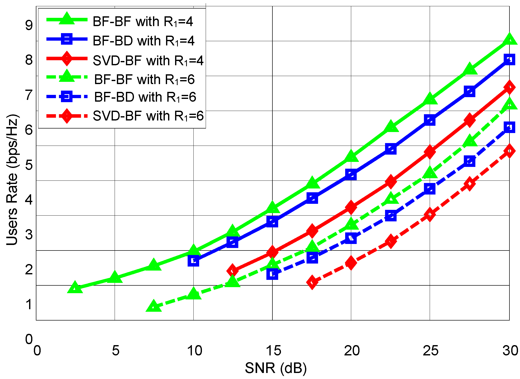
First, consider that both the SN and the RN are equipped with four antennas () and that both U1 and U2 are equipped with two antennas ().
Figure 2 shows a comparison of the system rates achieved by different pre-decoding schemes.
Based on Figure 2, we can draw the following conclusions:
- (1)
- The higher the rate requirement is for the main user, U1, the smaller the achievable rate is for the secondary user, U2. This is because for U1 to achieve a high rate, the RN can harvest less energy in the first timeslot; consequently, less energy is allocated to U2 in the second timeslot.
- (2)
- The precoding design that uses the BF algorithm at both the first and second timeslots achieves the optimal performance; however, considering the high complexity of the optimization algorithm, we proposed two sub-optimal algorithms: SVD and BD.
- (3)
- When there are fewer receiving antennas than transmitting antennas, the performance of the sub-optimal precoding design with the BD algorithm achieves a performance close to that of the optimal precoding design with the BF algorithm. This occurs because the interference signals can effectively map to the null space of the useful signal with the BD algorithm; thus, it achieves an excellent performance in cancelling interference effects. In contrast, the performance with the SVD algorithm significantly impacts the performance of the sub-channel; its effect is relatively poor, but the receiver is simple to design.
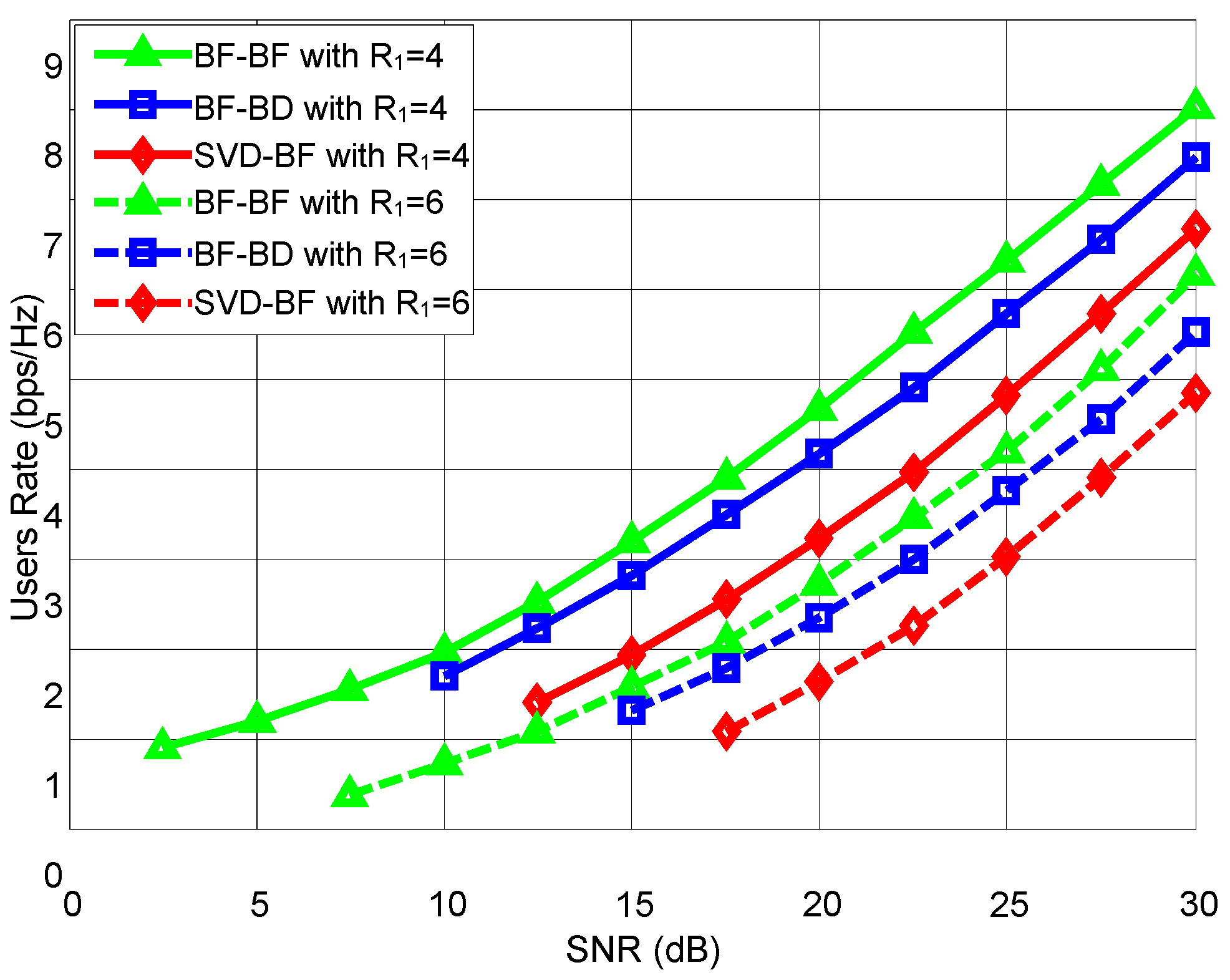
Finally, the condition that all nodes in the system are equipped with four antennas () has been considered. Figure 3 shows a comparison of the system rate for different pre-decoding schemes.
From Figure 3, we can conclude the following:
- (1)
- Increasing the number of antennas in a user’s receiving terminal effectively increases the system’s capacity. The optimized beamforming scheme is not affected by the performance of the separated sub-channels nor by the number of receiver antennas; therefore, it achieves the maximum rate, and the optimization effect is remarkable.
- (2)
- When the number of receiver antennas is larger than the number of transmitter antennas, the channel dimensions also increase, and BD can no longer effectively eliminate the signal interference between users, therefore, its performance is the worst among the three tested precoding designs.
6. Conclusions
This paper presented optimal and sub-optimal precoding designs and power allocation for a multiuser MIMO ad hoc network. The system rate is maximized based on a specified U1 rate requirement and the power-harvesting constraints of the relay nodes. First, an optimized precoding scheme based on a BF algorithm is proposed, and the optimal solution is obtained using the SDR strategy. Then, the suboptimal precoding schemes for two timeslots are given by the SVD and BD algorithms, respectively, to reduce the computational complexity caused by implementing the optimized precoding scheme. Finally, the results of simulations show that the precoding scheme can significantly improve system speed and has practical significance.
Acknowledgments
This work was supported in part by the National Natural Science Foundation of China under grant 61561032 and grant 61461029 and grant 61703197, in part by China the Jiangxi Postdoctoral Science Foundation Funded Project under grant 2014MT561879 and grant 2014KY046, in part by Young Scientists Project Funding of Jiangxi Province under grant 20153BCB23020 and grant 20162BCB23010, in part by the Natural Science Foundation of Jiangxi Province under grant 20114ACE00200, and in part by the Graduate Student Innovation Special Funds of Nanchang University under grant cx2016263.
Author Contributions
Haole Chen and Lin Xiao conceived and designed the experiments; Yinfeng Li performed the experiments; Dingcheng Yang and Xiaoxiao Zhou analyzed the data; and Haole Chen wrote the paper.
Conflicts of Interest
The authors declare no conflict of interest.
Appendix A. Proof of Theorem 1
Since P1-SVD is a convex problem, its optimal solution can be specified by using the KKT conditions. Let be the optimal Lagrange multipliers of Equation (21b,c), respectively. The KKT conditions for the problem P1-SVD can be described as follows:
where is the Lagrangian of Equation (21), given as:
Since represents the harvested energy P (in joules) at the RN during the first timeslot and information transmission cannot be ignored. The most interesting case occurs when and . Then:
If , Equation (27) transforms to , which was established only for , which makes no sense. Through comprehensive consideration of various circumstances, the following situation is more reasonable:
Therefore, the solution to the concave problem Equation (21) is: .
References
- Sudevalayam, S.; Kulkarni, P. Energy Harvesting Sensor Nodes: Survey and Implications. IEEE Commun. Surv. Tutor. 2011, 13, 443–461. [Google Scholar] [CrossRef]
- Zhang, R.; Ho, C. MIMO broadcasting for simultaneous wireless information and power transfer. IEEE Trans. Wirel. Commun. 2013, 12, 1989–2001. [Google Scholar] [CrossRef]
- Wu, F.; Xiao, L.; Yang, D.; Cuthbert, L.; Liu, X. Simultaneous Wireless Information and Power Transfer Mechanism in Interference Alignment Relay Networks. Mob. Inf. Syst. 2016, 2016. [Google Scholar] [CrossRef]
- Zhao, F.; Wei, L.; Chen, H. Optimal time allocation for wireless information and power transfer in wireless powered communication systems. IEEE Trans. Veh. Technol. 2016, 65, 1830–1835. [Google Scholar] [CrossRef]
- Sadek, A.K.; Liu, K.J.R.; Ephremides, A. Cognitive multiple access via cooperation: Protocol design and stability analysis. IEEE Trans. Inf. Theory 2007, 53, 3677–3696. [Google Scholar] [CrossRef]
- Chen, H.; Xiao, L.; Yang, D.; Zhang, T.; Cuthbert, L. User Cooperation in Wireless Powered Communication Networks With a Pricing Mechanism. IEEE Access 2017, 5, 16895–16903. [Google Scholar] [CrossRef]
- Khandaker, M.R.A.; Wong, K.K. QoS-based multicast beamforming for SWIPT. In Proceedings of the 2014 Eleventh Annual IEEE International Conference on Sensing, Communication, and Networking Workshops (SECON Workshops), Singapore, 30 June–3 July 2014; pp. 62–67. [Google Scholar]
- Grover, P.; Sahai, A. Shannon meets Tesla: Wireless information and power transfer. In Proceedings of the 2010 IEEE International Symposium on Information Theory Proceedings (ISIT), Piscataway, NJ, USA, 13 June 2010; pp. 2363–2367. [Google Scholar]
- Liu, L.; Zhang, R.; Chua, K.C. Wireless information transfer with opportunistic energy harvesting. IEEE Trans. Wirel. Commun. 2013, 12, 288–300. [Google Scholar] [CrossRef]
- Liu, L.; Zhang, R.; Chua, K.C. Wireless information and power transfer: A dynamic power splitting approach. IEEE Trans. Commun. 2013, 61, 3990–4001. [Google Scholar] [CrossRef]
- Zhou, X.; Zhang, R.; Ho, C.K. Wireless information and power transfer: Architecture design and rate-energy tradeoff. IEEE Trans. Commun. 2013, 61, 4757–4767. [Google Scholar] [CrossRef]
- Shi, Q.; Liu, L.; Xu, W.; Zhang, R. Joint transmit beamforming and receive power splitting for MISO SWIPT systems. IEEE Trans. Wireless Commun. 2014, 13, 3269–3280. [Google Scholar] [CrossRef]
- Yang, D.; Zhou, X.; Xiao, L. An Optimal Transmission Strategy for Joint Wireless Information and Energy Transfer in MIMO Relay Channels. Int. J. Antennas Propag. 2015, 2015, 1–6. [Google Scholar] [CrossRef]
- Devroye, N.; Mitran, P.; Tarokh, V. Achievable rates in cogtive radio channels. IEEE Trans. Inf. Theory 2006, 52, 1813–1827. [Google Scholar] [CrossRef]
- Nguyen, D.V.; Tran, N.L.; Duong, Q.T.; Shin, S.O.; Farrell, R. An efficient precoder design for multiuser MIMO cognitive radio networks with interference constraints. IEEE Trans. Veh. Technol. 2017, 66, 3991–4004. [Google Scholar] [CrossRef]
- Zhao, N.; Yu, F.R.; Sun, H.; Li, M. Adaptive power allocation schemes for spectrum sharing in interference-alignment-based cognitive radio networks. IEEE Trans. Veh. Technol. 2016, 65, 3700–3714. [Google Scholar] [CrossRef]
- Yang, D. Wireless Information and Power Transfer: Optimal Power Control in One way and Two-way Relay System. Wirel. Pers. Commun. 2015, 84, 1–14. [Google Scholar] [CrossRef]
- Khurana, M.; Ramakrishna, C.; Panda, S.N. Capacity Enhancement using MU-MIMO in Vehicular Ad hoc Network. Int. J. Appl. Eng. Res. 2017, 12, 5872–5883. [Google Scholar]
- Yue, W.; Li, C.; Song, Y.; Xiong, L. Dynamic time slot allocation and stream control for MIMO STDMA in ad hoc networks. EURASIP J. Wirel. Commun. Netw. 2017, 2017, 100. [Google Scholar] [CrossRef]
- Yang, D.; Zhou, X.; Xiao, L. Energy cooperation in multi-user wireless-powered relay networks. IET Commun. 2015, 9, 1412–1420. [Google Scholar] [CrossRef]
- Bi, S.; Ho, C.K.; Zhang, R. Wireless powered communication: Opportunities and challenges. IEEE Commun. Mag. 2015, 53, 117–125. [Google Scholar] [CrossRef]
- Grant, M.; Boyd, S. CVX: Matlab Software for Disciplined Convex Programming, Version 1.21; Available online: http://cvxr.com/cvx/ (accessed on 11 October 2017).
- Liu, L.; Zhang, R.; Chua, K.C. Secrecy Wireless Information and Power Transfer With MISO Beamforming. IEEE Trans. Signal Process. 2014, 62, 1850–1863. [Google Scholar] [CrossRef]
Figure 1.
System model.
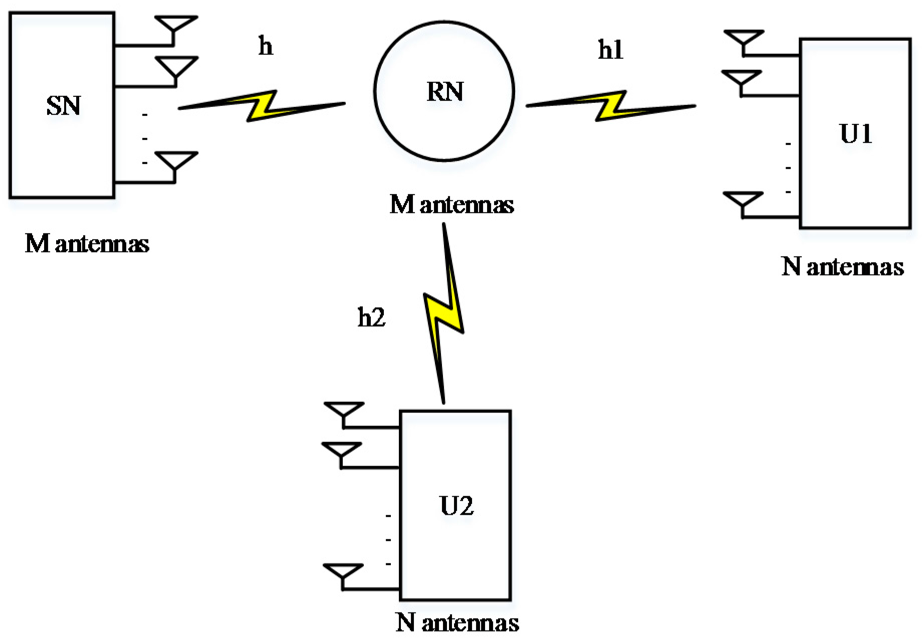
Figure 2.
When N = 4, M = 2, the second user’s rates with different precoding designs based on different rate requirement for the main user.
Figure 2.
When N = 4, M = 2, the second user’s rates with different precoding designs based on different rate requirement for the main user.

Figure 3.
When N = 4, M = 4, the second user’s rates with different precoding designs based on different rate requirements for the main user.
Figure 3.
When N = 4, M = 4, the second user’s rates with different precoding designs based on different rate requirements for the main user.

© 2017 by the authors. Licensee MDPI, Basel, Switzerland. This article is an open access article distributed under the terms and conditions of the Creative Commons Attribution (CC BY) license (http://creativecommons.org/licenses/by/4.0/).
Share and Cite
MDPI and ACS Style
Chen, H.; Xiao, L.; Li, Y.; Yang, D.; Zhou, X. Precoding Design and Power Allocation in Two-User MU-MIMO Wireless Ad Hoc Networks. Symmetry 2017, 9, 247. https://doi.org/10.3390/sym9110247
AMA Style
Chen H, Xiao L, Li Y, Yang D, Zhou X. Precoding Design and Power Allocation in Two-User MU-MIMO Wireless Ad Hoc Networks. Symmetry. 2017; 9(11):247. https://doi.org/10.3390/sym9110247
Chicago/Turabian StyleChen, Haole, Lin Xiao, Yinfeng Li, Dingcheng Yang, and Xiaoxiao Zhou. 2017. "Precoding Design and Power Allocation in Two-User MU-MIMO Wireless Ad Hoc Networks" Symmetry 9, no. 11: 247. https://doi.org/10.3390/sym9110247
Note that from the first issue of 2016, this journal uses article numbers instead of page numbers. See further details here.