Virtualized Network Function Orchestration System and Experimental Network Based QR Recognition for a 5G Mobile Access Network


1
Department of Computer Engineering, Kyung Hee University, Gyeonggi-do 17104, Korea
2
Humanitas College, Kyung Hee University, Gyeonggi-do 17104, Korea
*
Author to whom correspondence should be addressed.
Symmetry 2017, 9(12), 300; https://doi.org/10.3390/sym9120300
Submission received: 17 October 2017
/
Revised: 25 November 2017
/
Accepted: 29 November 2017
/
Published: 3 December 2017
Abstract
:This paper proposes a virtualized network function orchestration system based on Network Function Virtualization (NFV), one of the main technologies in 5G mobile networks. This system should provide connectivity between network devices and be able to create flexible network function and distribution. This system focuses more on access networks. By experimenting with various scenarios of user service established and activated in a network, we examine whether rapid adoption of new service is possible and whether network resources can be managed efficiently. The proposed method is based on Bluetooth transfer technology and mesh networking to provide automatic connections between network machines and on a Docker flat form, which is a container virtualization technology for setting and managing key functions. Additionally, the system includes a clustering and recovery measure regarding network function based on the Docker platform. We will briefly introduce the QR code perceived service as a user service to examine the proposal and based on this given service, we evaluate the function of the proposal and present analysis. Through the proposed approach, container relocation has been implemented according to a network device’s CPU usage and we confirm successful service through function evaluation on a real test bed. We estimate QR code recognition speed as the amount of network equipment is gradually increased, improving user service and confirm that the speed of recognition is increased as the assigned number of network devices is increased by the user service.
1. Introduction
Future mobile network experience two challenges. First is the traditional problem—the performance or data-rate. Second is the new issues—the low latency and the cloud-based network services. According to the first topic, modern society has experienced a rapid data traffic volume increase, since the emergence of smartphones, which has created a dramatic increase in the number of mobile users and mobile services. In fact, data traffic volume increase caused by mobile equipment such as smartphones, portable PCs and tablets increased by 65% in 2015’s third quarter compared to that in 2014’s third quarter [1]; moreover, its level is expected to reach 24.3 EB (Exabyte) in 2019 [2]. With the emergence of drastically increased mobile data traffic, it is essential to have 5G network technology for innovation and evolution of original networks. Recognizing this demand, research on 5G networks is being conducted worldwide and Europe’s mobile and wireless communications enablers for twenty-twenty information society (METIS 2020), the 3rd Generation Partnership Project (3GPP), 5GPP, China’s IMT-2020 and Korea’s 5G forum and other various relevant groups are discussing the vision and requirements for 5G networks [3,4].
About the second issue—the low latency and the cloud-based network services, technologies for the datacenters of the IT companies, such as Google and Amazon, are deployed into the Telco’s mobile networks. The cloud computing of the IT companies enables the hardware and software separation in Telco’s networks, which means the traditional hardware product-oriented network architecture changes to the function-oriented flexible network architecture. By using cloud computing technologies, telecom companies can enable the access and core networking functionalities at the optimal place with dynamically managed capacity. This idea changed the fundamental of the mobile networks and the 5G uses these concepts as the underlying principle for the future network design. The 5G network is based on virtualization different from the original network system. It is based on software-defined networking (SDN) and network function virtualization (NFV). In particular, NFV technology enables networks to be maintained in a cost-efficient way by replacing previously necessary physical appliances with virtualized environments. 5G networks applying this technology have the advantage of comprising flexible networks by arranging virtualized network function (VNF), which is virtualized according to the user’s requirement. However, to apply NFV technology, IT virtualization and cloud technology is needed and to apply this technology, equipment with high specifications is required. This can result in difficulties in usability outside the cases of communications enterprises or data center management corporations [5]. So, various researchers have been conducted on the topic of cost-optimal design of 5G virtualized networks recently [6,7,8,9].
However, it is not enough to solve the requirements about the low latency service and the cloud computing based network services as in Figure 1. The cloud computing based network service examples are the thin-clients (e.g., Google Chromium OS) [10], the voice user interface intelligent services (e.g., Apple Siri, Google Now and Speech, Amazon Alexa and Echo), the multimedia MMORPG computer games and the interactive virtual and mixed reality services. The commonality of these services is that the user’s smartphone or computer equipment is mainly used for input and output with the user and most of the computing processing is done on the servers of the network. Therefore, the communication delay in the network must be very small and a network structure in which the user’s service can be dynamically driven at a desired place flexibly in order to allow users to freely use such a service anytime and anywhere. Recently, research on MEC (Mobile Edge Computing) has been actively started for such a network [11]. This should be viewed as a resource for cloud computing and to ensure that the user’s services are running smoothly. Therefore, the network service software should be located dynamically to the location closest to the user and the transport layer of the network should also be capable of ultra-low latency. This makes it possible for users to experience the same processing as if they were using their network-based services.
Thus, we deal with the virtualized network function orchestration of cloud computing-based network services in mobile networks. We propose a new architecture which enables the flexible network service deployment and orchestration over the future mobile network like Beyond 4G and 5G mobile work. And, to evaluate the proposed architecture, we deploy a real cloud computing based QR code recognition application. Thus, we design and implement the new architecture and network applications in a real testbed system and proved the feasibility and performant of the proposed architecture. Especially, in consideration of the cost of 5G network settings, this paper discusses using low-cost equipment for virtualization in a network orchestration system to reduce CAPEX and OPEX further based on requirements.
Short description about the real system testbed, tree and mesh networking technology for wireless network connections between the network and Docker, which is a light-weight open-source virtualization technology, is used [12]. The mobile network is traditionally tree-based hierarchical network in both access and core network but as the millimeter wave (mmWave) technologies are used in 5G mobile networks, radio cell size is relatively smaller than conventional 3G/4G networks. Thus, mobile backhaul should be used to connect adjacent mmWave base-stations to reduce the wired backhaul CAPEX/OPEX. Thus, we consider mesh-network topology also for our contribution and a real testbed construction. In a real testbed system, by using the technologies mentioned above, a virtualized network function orchestration system for 5G mobile access networks is designed and implemented. The proposed system can be built with general hardware and open-source software based on virtualization technology and can provide high availability by providing seamless network function. Thereby, we can achieve network infrastructure with much lower cost and quickly adopt network/user service. Furthermore, through low adoption/development cost, we can activate network building in developing countries and provide computing environments more widely. Furthermore, by selecting the open hardware and software platform—Raspberry Pi, as the network device for the proposed system’s evaluation, we enable system composition at low cost [13]. Moreover, the necessary characteristics for a virtualized network function orchestration system for 5G mobile access environments are defined and verified by establishing a system that can satisfy this need.
Also, this paper proposes a QR code recognition method that uses an image-matching method and advances existing research. However, the proposed virtualization based network architecture is not limited to the QR code reorganization services and it can be used in wide areas in mobile network services. This study does not operate existing QR identification software on the proposed platform. The existing QR code recognition recognizes the QR code through the software inside the terminal such as a smartphone—a stand-alone approach. However, we proposed a new QR code recognition technology based on cloud computing in the network in the proposed virtualization environment—a network computing approach. Through this, the recognition rate of the QR code recognition is greatly improved and the virtual network based service architecture can demonstrate that the performance of the actual application service can be improved. More about the proposed network based QR code recognition technology, this has the purpose of reducing the device’s workload to solve the existing recognition problem by performing distributed processing of many images through previously discussed cloud environments like Docker. Actually, the original QR code recognition order starts with recognizing the three finder patterns. However, finder pattern recognition methods have the problem of not recognizing a pattern’s specific ratio when QR codes are not scanned accurately from the front side. Above a certain angle, the pattern’s original ratio is broken and it cannot be recognized even in a high-definition image taken at close distance. We enhance the recognition performance with scalable computing and big-data approach at the edge side of the mobile networks.
The structure of this paper is as follows. The first and second sections introduce and explain the virtualized network function orchestration system and related research. The third section explains the system and its characteristics and the fourth section introduces and analyzes the evaluation of the function implemented in a real test bed. And, we conclude the paper in the fifth section with a summary and considerations for possible future works.
2. Related Works
Related research includes wireless mesh networks, which are connection-oriented and favorable for automatic network composition and Docker cloud platforms for implementing the virtualization. Additionally, since this paper evaluates the performance of multiple image search forms’ QR code recognition as the proposed orchestration system’s use case, it explains the QR code recognition method, which is relevant original research. This section explains the above related research and discusses its differences from the proposed method in this paper.
2.1. Wireless Mesh Networks
As mentioned previously, wireless mesh networks are the appropriate networking technology for connection-oriented network composition. In particular, wireless mesh networks have the characteristics of self-composition and self-recovery and have the advantage that they can communicate with other paths even if the original path is disconnected [14]. Hence, with reduced cost and time in composing network deployment considering infrastructure-based wireless mesh networks, the network function orchestration system is shown to be appropriate.
However, in the status quo of mesh network composition, since the amount of information exchange for routing increases according to network size, there is a trend of overhead drastically increasing. In particular, in order to compose dynamic networks that are characteristic of mesh networks, every termination needs to be recognized and searched in the form. Hence, in order to reduce this overhead, research for developing wireless mesh network routing is currently active.
Routing research in wireless networks has been actively pursued, focusing on mobile ad hoc networks, routing protocols including dynamic source routing (DSR), ad hoc on-demand distance vector routing protocol (AODV) and optimized link state routing protocol (OLSR) have been developed [15,16]. In particular, the IEEE 802.11s wireless mesh networks standard uses the hybrid wireless mesh routing protocol (HWMP) [13]. This routing protocol has a structure that combines AODV and tree-based routing and conducts double-layered routing. However, the above methods all require a large amount of time, or have the disadvantage of incurring more overhead with routing table update process.
Thus, this paper composes flexible networks by reducing network overhead, applying Better Approach to Mobile Ad hoc Networking (BATMAN) routing protocol. This method implements routing based on the information of nearby nodes, in contrast to the original mesh network routing method, which needs to recognize the information of all nodes.
BATMAN
BATMAN, invented by the Freifunk community, is a multi-hop routing protocol for mobile ad hoc mesh networks [17]. This protocol was invented to overcome the limitations of the OLSR protocol and to replace it.
This protocol implements routing in double-layered fashion instead of triple-layered, enabling communication between terminals without an IP. From this point of view, it has the advantage that it is easy to connect with non-mesh terminals.
The BATMAN protocol does not have a routing table for each node, unlike the original protocol and also has information regarding nearby nodes; therefore, it does not suffer from onerous overhead during the routing table update procedure.
This protocol’s operation process is as follows. Each node broadcasts the originator message (OGM) and notifies nearby nodes of the existence of a note. The nodes that receive the message broadcast the OGM message again. The OGM has a size of 52 bytes in a small packet, including the message’s start address, the address where the packet has been delivered, TTL and the sequence number. Ultimately, each note, through OGM, can update the optimum node among the nearby nodes, know the optimum path between terminals and obtain information regarding link functions. Through the above procedure, without incurring excessive routing overhead, providing an optimum path is possible; and since table correction becomes faster owing to the terminal’s move, a much more flexible mobile mesh network can be constituted.
2.2. Docker Virtualization Technology
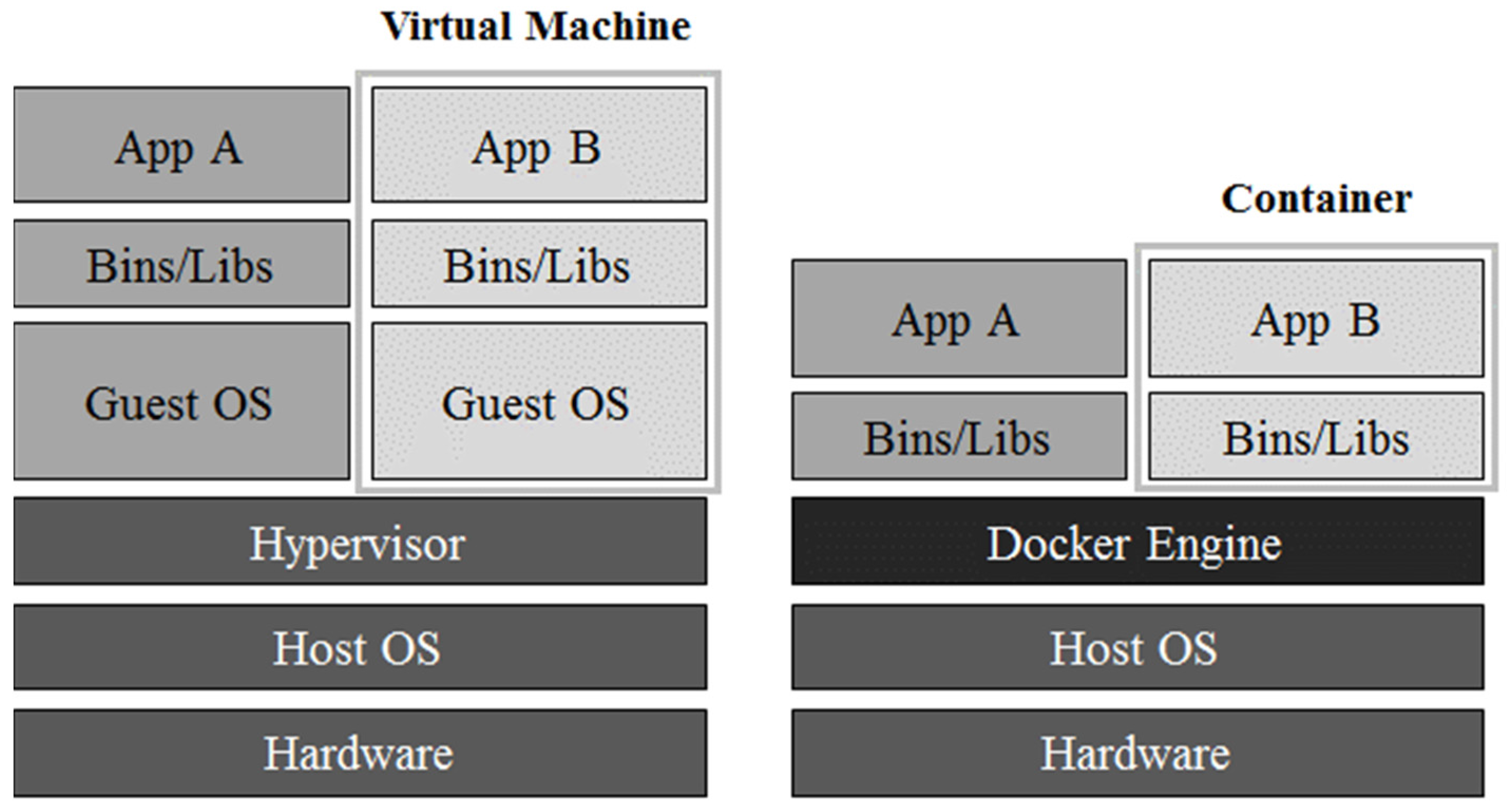
A docker is a light-weight, open-source virtualization technology. It provides light-weight virtualization by using a container based on LXC, which has a different form from the original virtual machine. Figure 2 shows a hierarchy diagram of a virtual machine and Docker, which shows the hierarchical difference between the two technologies. As illustrated for the case of a virtual machine, resources are allocated based on a hypervisor and the new guest management system is then executed, which has the problem of performance reduction due to excessive overhead. On the other hand, in the case of a docker, by using the form of host management system and sharing the resources and adding the library and executable files that are needed for the implementation of application, instead of using the form of newly creating guest management system, a container is created. Thus, since a Docker creates less overhead than a virtual machine and requires smaller file size to create the container, it can be quickly installed. Based on these characteristics, a Docker is flexible in version management, capable of using resources efficiently and has the advantage of application portability.
However, it has the disadvantage that it cannot realize the migration function owing to the container composition provided by the virtual machine. Because of this, when a container is relocated, there is the problem that the container’s service starts from the beginning.
To locate and manage the virtualized network function in the proposed orchestration system, a Docker swarm, which is a cluster management tool, is used [18].
Docker Swarm—Docker Container Cluster Management Tool
A docker swarm is a container cluster management tool that uses the standard Docker API and implements clustering by communicating with a node on which a Docker demon is implemented. Additionally, because it provides a swarm API, it is possible to implement functions such as container relocation or destruction. This has the advantage of recognizing cluster node resources and container distribution.
Figure 3 shows the necessary network device’s basic structure in order for a Docker swarm to be activated. Firstly, the node that created the swarm master container is activated as the master node and nodes that implemented the swarm agent container are activated as slave or member nodes. The connection of these nodes involves a procedure wherein the master node is recognized through a token and the token is created through a Docker hub and can be checked. Between containers that are created by the same tokens through the Docker API, a master node can collect the information regarding the connected nodes’ container and network systems.
The token method previously mentioned is capable of recognition between nodes only under the circumstances of internet connection and there is another way to recognize nodes using static IPs. However, since in this paper the Docker swarm is used offline, a token method that allows swarm managers to recognize the agent is not suitable and composing clusters by using static IPs is also unsuitable in an environment that requires dynamic network composition.
Thus, the proposal in Section 3 is a clustering composition method that uses a Docker swarm tool and chooses the recognition option that is suitable for the environment. Using this method, a system environment that can locate virtualized network functions is discussed.
2.3. QR Code Recognition Method
QR codes were developed by the Denso Wave Incorporated in Japan in 1994 for the purpose of increasing information quantity and minimizing information damage to 1D barcodes such as European Article Number (EAN)/Universal Product Code (UPC), which are known as the original barcodes [19]. QR codes are 2D barcodes designed to read in information once 30 to 700 times faster than original EAN/UPC barcodes. Furthermore, they can handle content including but not limited to numbers, English, Chinese characters, Korean characters, symbols, binary and control codes. Furthermore, they can express letters or numbers up to 7089 in a single code. 2D codes include error-restoring functions so that they are not adversely affected, even faced with some information damage, owing to their ability to supplement the deficiencies of original bar code.
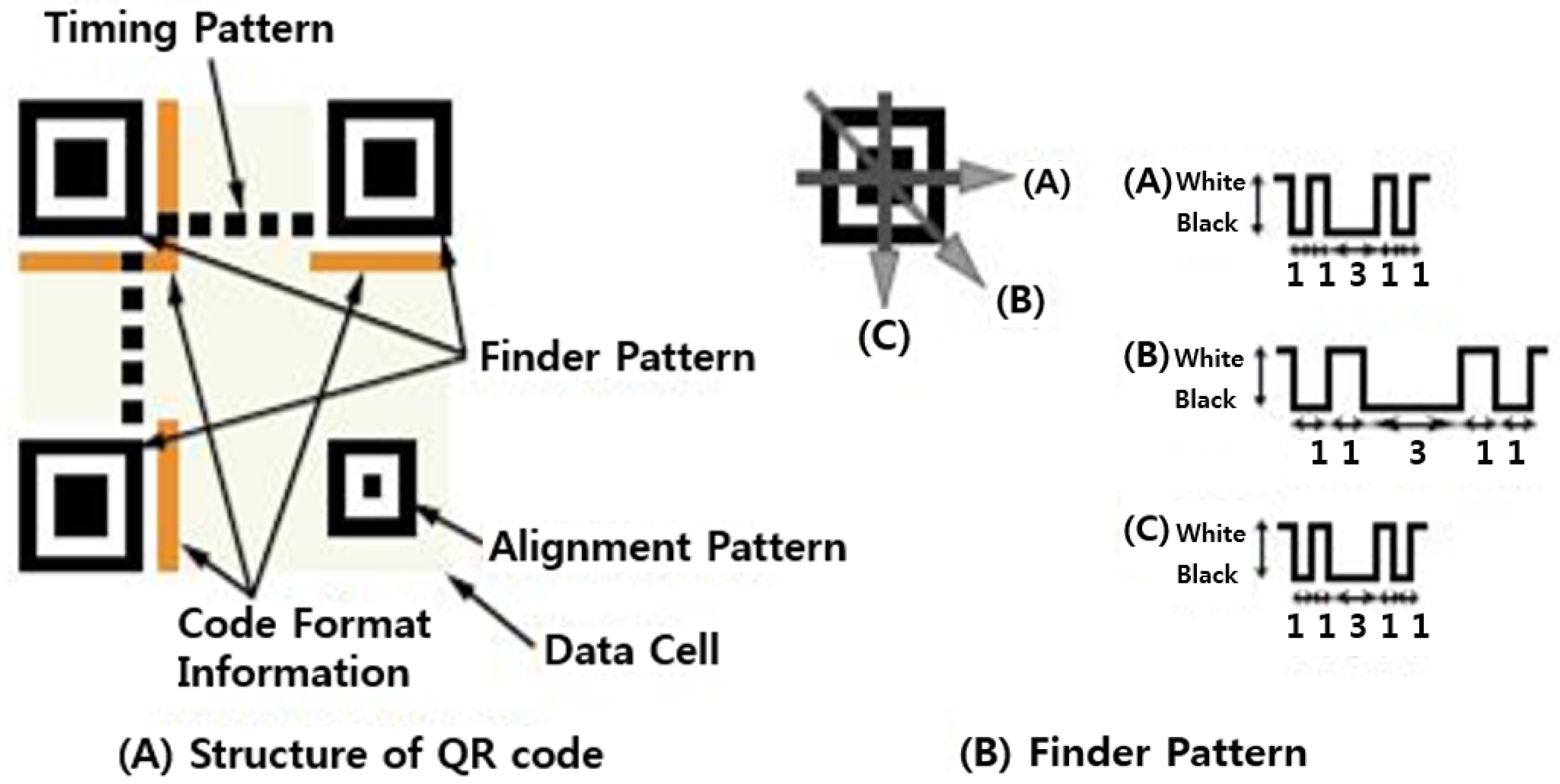
One characteristic of QR codes is that it is possible to recognize them in any direction. The reason for this is that they have three finder pattern symbols as shown in Figure 4, which enables recognizing QR codes using these patterns [19]. Since these patterns have a white-to-black ratio of 1:3:1:1 in any direction, QR codes are recognizable in any direction.
With the above advantages, QR codes are usefully utilized in various situations, such as printed fliers, name cards, payment systems and factory or distribution businesses. As the boundary of usage has increased to various new fields, ways of recognizing QR codes have been studied extensively [20,21,22].
The original QR code recognition order starts with recognizing the three finder patterns. With three patterns around the center, reading proceeds by finding information including the size of the module and its format and then decoding the QR code based on this. Researchers in recognition methods have developed recognition methods by focusing first on ways to recognize finder patters.
However, finder pattern recognition methods have the problem of not recognizing a pattern’s specific ratio when QR codes are not scanned accurately from the front side. Above a certain angle, the pattern’s original ratio is broken and it cannot be recognized even in a high-definition image taken at close distance.
3. Proposed Virtualized Network Function Orchestration System
Before going into details, the definitions of the characteristics needed in the proposed system are explained. First, the system must be in a form that can expand easily to a connection-oriented system. Since this is not a wired network composition, in wireless situations, seamless connection between network devices is important and scalability based on the situation must be confirmed. Secondly, the system needs to provide ensured service to users. Since every network function is activated in a container which is a virtual environment, before the container is concluded, the virtualized network function recovery procedure is necessary, moving it to another network device. Lastly, according to the device’s condition, the system must decide the network function arrangement; through this, it should distribute the workload. Considering these characteristics, the proposed orchestration system is discussed below.
This section explains the composition method and procedure of the proposed virtualized network function orchestration system. In addition, as a solution to the recognition problem related to QR codes’ scanning angles, we explain a QR code recognition method based on the multiple-image search method. This is a suitable recognition method for environments that can locate the service spread, using the proposed orchestration system. By applying this recognition method to user service using a virtualized network function orchestration system, the system’s distributed arrangement function is checked.
3.1. Network Automatic Configuration Method Based on Bluetooth Low Energy (BLE)
This paper proposes a networking method based on Bluetooth beacons for automatic mesh network configuration between a network’s devices. Firstly, mesh networks are suitable for dynamic wireless network configuration and are effective for configuring a connection-oriented configuration, as explained above. This configuration has the purpose of automatic network configuration that can dynamically configure when a network is needed rather than a network that needs to previously register the same Service Set Identifier (SSID) and channel information for a particular purpose. To dynamically configure the network upon request or input, a Bluetooth beacon is used. Additionally, allowed network devices with Bluetooth beacons can easily enter a network, which leads to advantages in network configuration and expansion in mobile environments. By transmitting network information and activating a nearby terminal’s network devices using a beacon, network configuration following a user’s requests is made possible.
First, through Bluetooth beacons, a device transmitting network information is activated as the master node and other devices on the same network are categorized as member nodes. The determination of master and member nodes is made by the network device that created a mesh network in the first place and, following the user’s requests or input, various network devices can be activated as the master node. This node, to receive the user’s request, creates an access point for the user’s access, excluding the access point for the mesh network. For this, the master node needs to have one more network interface that allows it to obtain the response from this node and provide the requested service. Next, to transmit the data through the service request, a network device needs two things: a network interface card for network configuration and a network interface card for user acceptance.
Next, in clustering using a Docker swarm, the network’s mater node becomes the Docker swarm’s master and member nodes are activated in the role of agents. However, the situation wherein network devices are simultaneously on is then excluded and it is assumed that one device can be activated as the master first.
Every node, as in Figure 5, has a monitoring module to recognize beacon information and a mesh network controller module to establish the network with the information received through the beacon. Each module’s operational process is explained in detail below.
Bluetooth-Beacon-Based Mesh Network Controller
To realize the proposed Bluetooth-beacon-based mesh network controller, a BLE packet monitor and mesh network controller that recognize the Bluetooth beacon packet are needed.
Figure 6 and Figure 7 shows the master node’s and member node’s mesh network controllers’ operational process, respectively. As mentioned above, the network device that first received the network information input is activated as the master node.
First, the master node’s controller (Figure 6) configures the mesh network that used the BATMAN protocol based on the information received by using the device’s wireless network interface. The proposed mesh network configuration needs information regarding SSID, channel and IP address as well. This procedure composes the network in a faster way and enables configuring the network using low-energy Bluetooth, which is more energy-efficient than using a wireless beacon. In order to communicate through a Bluetooth beacon, each network device activates its BLE-packet-monitoring module. Thereby, it sends a message that wakes up similar nodes with the Bluetooth beacon packet and then broadcasts. By receiving the beacon packet that responded to the WAKE_UP message, the device obtains the Bluetooth MAC address. Through the obtained address, it transmits the mesh network information stored in the mesh network controller and implements a confirmation procedure as to whether every device received the response or not.
The response confirmation procedure and following procedures differ according to the user’s input. The implementation procedure is divided into two cases: the situation of continuously providing a network connection and the situation of providing the network connection for a limited time. According to the previous procedure, when the response was confirmed for every device that received the message, for the support of the new device’s network configuration, a WAKE_UP message is transmitted and the procedure of providing network information once again is implemented. In the case where all responses do not return, the procedure resubmits network information to the Bluetooth MAC address that is obtained in previous step. Before the master node’s controller device concludes, this procedure takes the role of transmitting the Bluetooth beacon signal to the near side continuously. In the opposite case, even if all responses have been received, if a certain amount of time passes, the WAKE_UP message is not created. When the response is not received, the procedure is the same as the previous procedure. This procedure, after a certain amount of time, ends the controller and is suitable for structures that do not require network expansion.
In the first instance, network information can be broadcast in a Bluetooth beacon packet since the network environment provides service to users but it does not allow the inflow of every node and through this procedure mutual cognition can be performed.
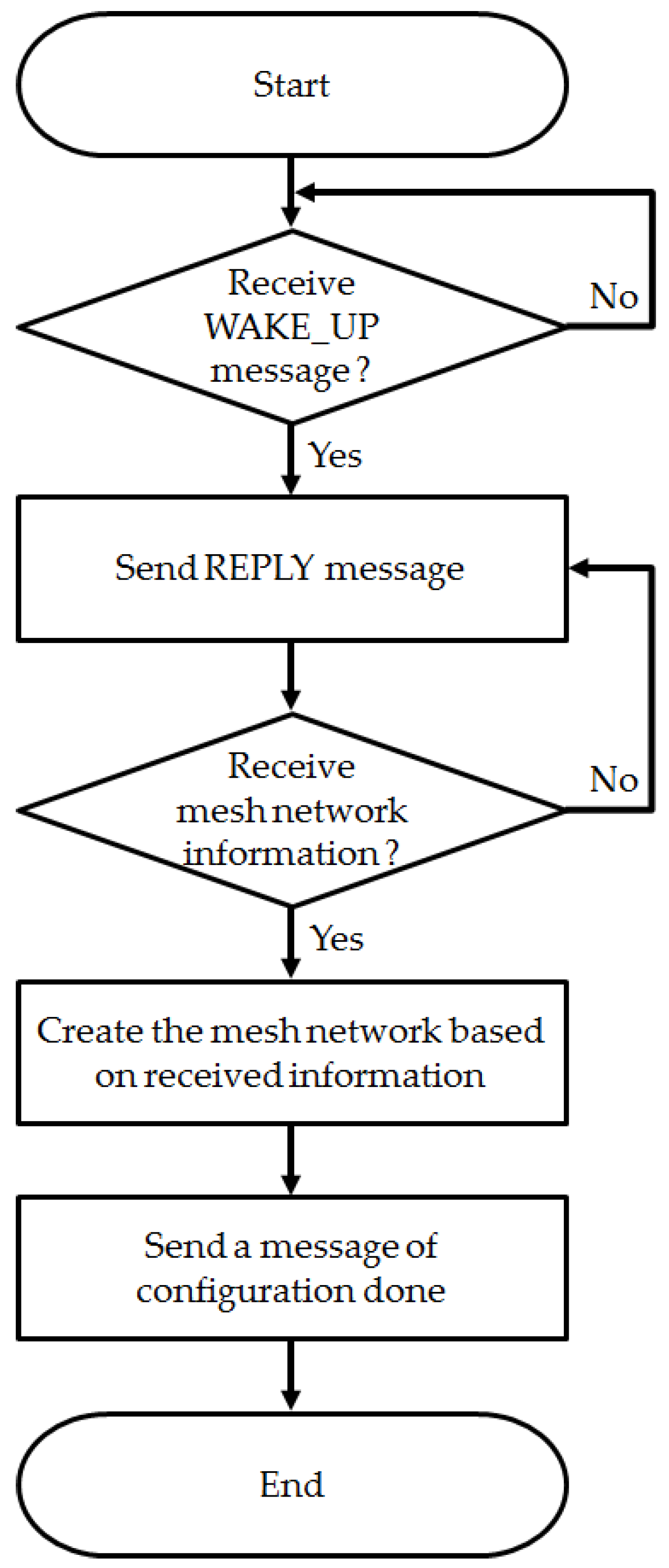
A member node, as shown in Figure 7, scans the WAKE_UP message through its BLE-packet-monitoring module. When the WAKE_UP message arrives through a received packet, it obtains the master node’s MAC address and responds. When a Bluetooth beacon packet that contains a network address arrives at the same address, by using this result (in the same condition as for the master node), the mesh network is configured through the device’s wireless network interface. When the configuration is finished, a completion message is sent and the process concludes.
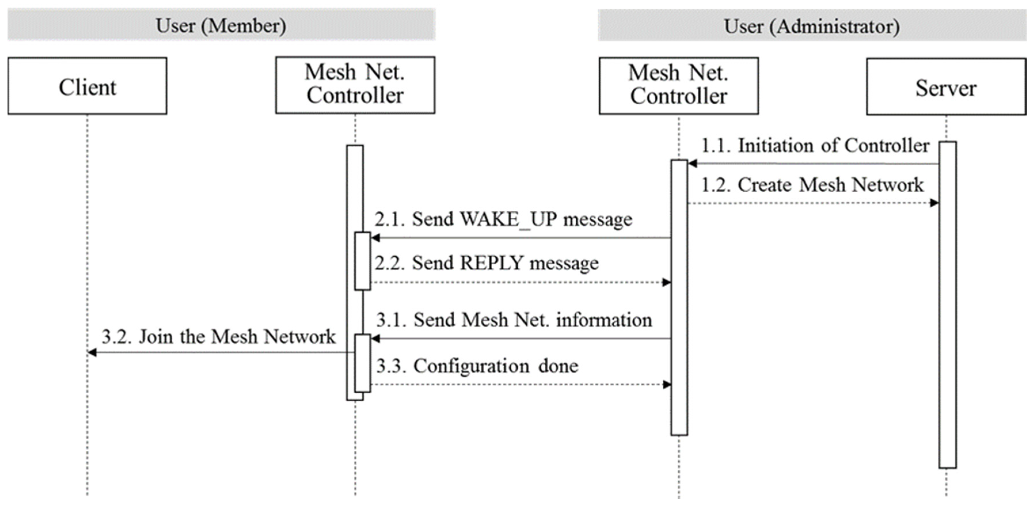
Figure 8 shows the mutual recognition and information exchange process of the proposed mesh network controller. The following content shows the order of each node’s operational process.
As process 1.1, the master node transmits information from the user to the mesh network controller and, based on this information, the module in process 1.2 broadcasts the message that awakens nearby similar nodes as process 2.1 through a Bluetooth beacon packet. Next, it receives the beacon packet that responds from the master node’s BLE-packet-monitoring module to the Bluetooth MAC address and, as in process 3.1, it transmits the information for the mesh network controller to the Bluetooth MAC address received from the incoming packet.
As in process 3.1, a member node transmits the received information to the mesh network controller through its BLE-packet-monitoring module and as in process 3.2, it participates in the network by composing a mesh network through the received information. After network configuration, the member node’s mesh network controller transmits a ‘setup completed’ message to the master node’s module. This process is shown in Figure 8 as process 3.3.
3.2. Cluster Management Method for the Arrangement of VNFs
This paper proposes a form of arranging service in a dynamic way as a 5G network with cluster composition for virtualized network function arrangement based on dynamic network composition. As explained above, since a Docker is lighter than the existing virtual machine, it is suitable for use in the proposed method to compose a system using open-source hardware. However since a container is activated with the process, it cannot provide functions like virtual machines when relocation or movement is conducted. Virtual machines, when restarted from the stopped condition, can provide continuity by starting from the stopped point; but in the case of a container, since it needs to start from the very beginning, it cannot provide continuity, which is a deficiency. The proposed virtualized network function orchestration system explains the method of providing continuity for the container and through this, it presents a method that has low overhead and provides service continuity. The proposed method based on the Docker virtualized platform, network resource sharing between devices using a Docker swarm and load monitoring, locates network functions. When actions such as relocation are committed, a method is proposed for restarting from the point at which the process stopped by reporting the action status.
As seen in the network configuration method above, the roles of the master and member nodes is the same and the Docker swarm manager container is created at the master node while, at member nodes, the Docker swarm agent container is distributed. While the existing Docker swarm recognition method is a Docker-hub-based online method, the proposed method achieves recognition offline through IP, replacing the IP information given during network setting.
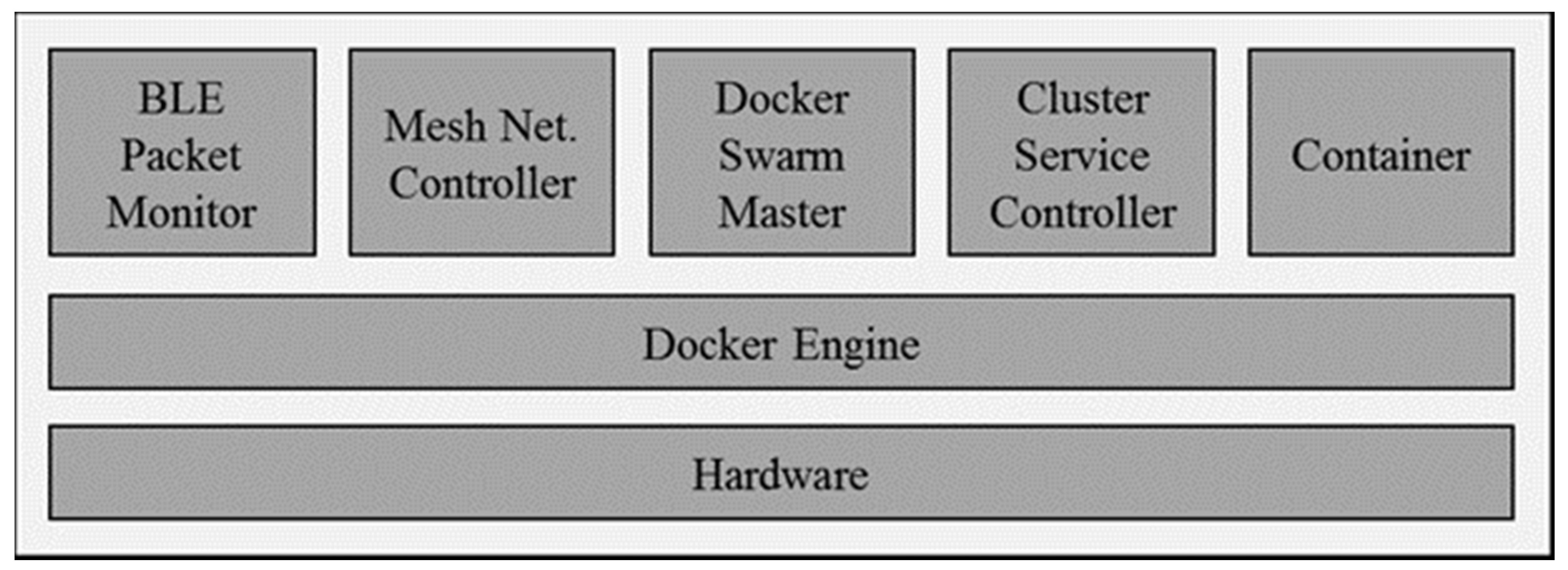
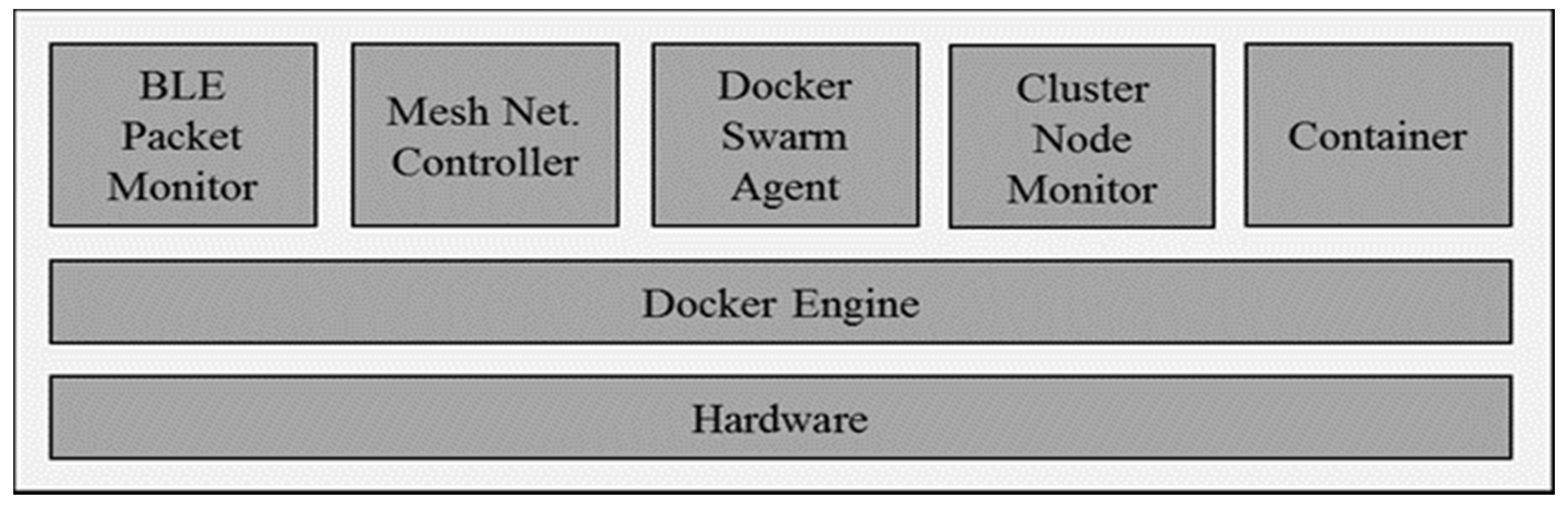
As shown in Table 1, through the Docker swarm API, although the master can obtain other network device information, it is not suitable to judge the network status using the number of containers. In the status quo, the information that we can gain from the Docker swarm is limited; so, in order to achieve flexible container location and movement, a module that can check CPU usage at each node is needed. Therefore, as shown in Figure 9, member nodes help in the configuration of a cluster with the previously proposed module and Docker swarm agent and, through cluster node monitoring, it can monitor CPU usage and report to the master node when there is an error.
When a member node notifies that CPU usage is over a given limit, by collecting the status of each node, the master node moves the container to the node at which the error occurred to the optimal node so that it can continually provide network function.
To achieve this, the master node is operated as depicted in Figure 10 (as previously proposed), with a Docker swarm master and a cluster service controller.
The proposed operating procedure is shown in Figure 11. Firstly, every node implements the cluster node monitoring module and checks its own CPU usage at set times. The master node waits for error message reports from member nodes and prepares for incoming messages by opening a port. If, as in process 1, the CPU loading rate exceeds a threshold value at some nodes, process 2’s error message is reported to the master node. In the error message, the container’s last status needs to be written and sent. At this time, the master node sends the request message regarding CPU loading information to the all nodes and then receives messages from the responding nodes, leading to a search for the node with the lowest CPU usage. Through this procedure, the master node searches for the optimal node and locates the error node container. Then, by delivering the status information to the container, it implements service without any suspension. When the error is located as in process 4, the master node terminates the container at the node at which the error occurred and concludes the service recovery procedure.
By using this composition method, it is possible to flexibly locate containers according to the network devices’ statuses; and by providing a recovery procedure that moves the virtual network function of the device at which the error occurred, it can prove the availability of service. Additionally, based on the entire network’s information acquisition, since it is possible to locate the network’s function according to device status, when locating, it is possible to distribute the load of the entire network considering network device information.
This method is a way to provide network function but it can also be used as a method to provide user services. When it provides video streaming service as the user service, as in the previous operation, when a network device experiences an error, service can be recovered by moving service to another device. The idea involves not only restarting streaming services; by also sending information with the same amount of storage as the service information, it can provide service continuously.
3.3. Cluster Management Method for the Arrangement of VNFs Image-Matching-Based QR Code Recognition Method
This paper proposes a virtualized network function orchestration system’s user service use case, proposing a QR code recognition method using a multiple-image-matching method. This method, based on the cloud, is a way to check a database that saves images according to different angles of scanning QR codes and the similarity of the imaged QR codes. Since QR codes have an image for each scanning angle, QR codes can be recognized even from angles at which they normally cannot be recognized.
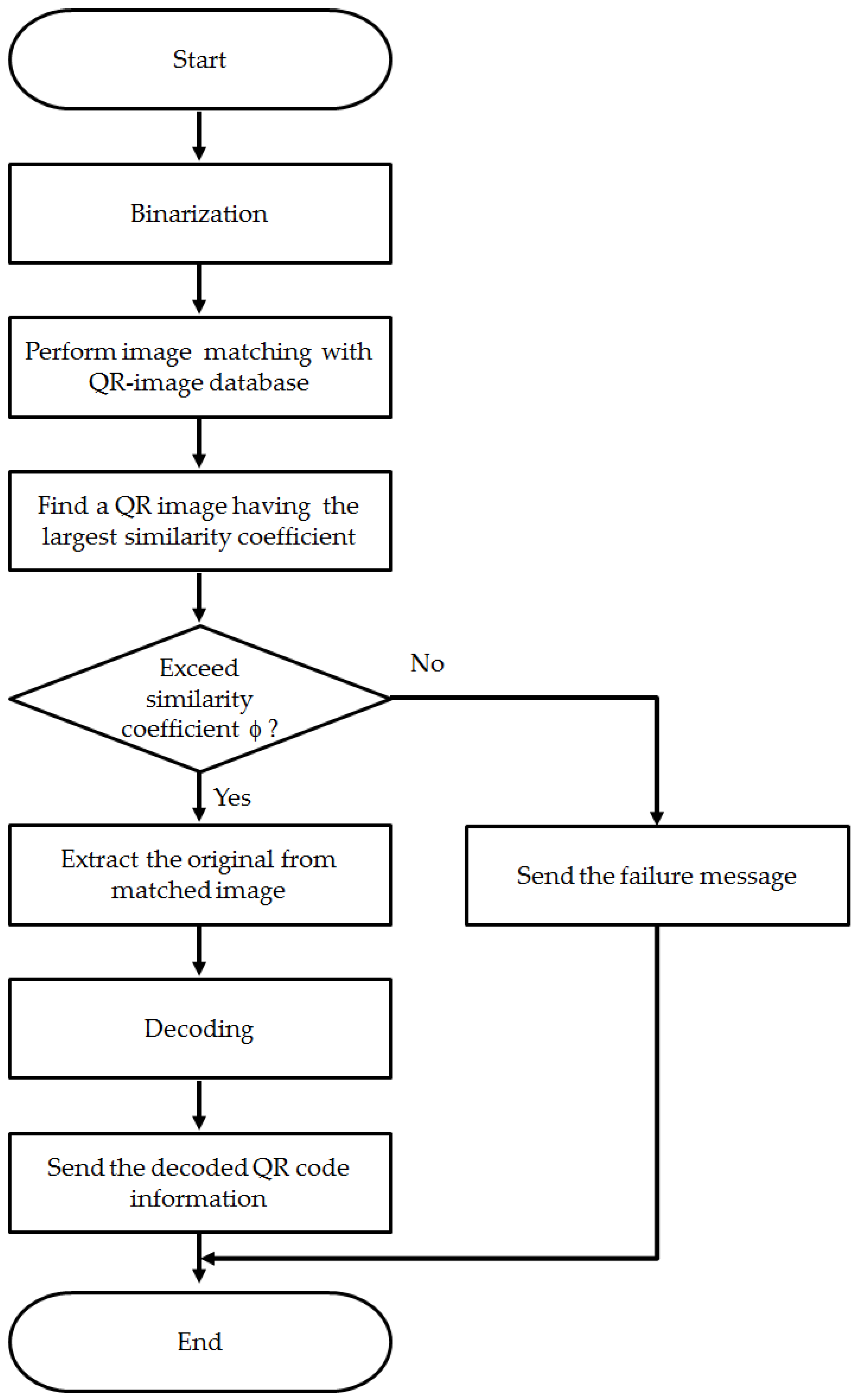
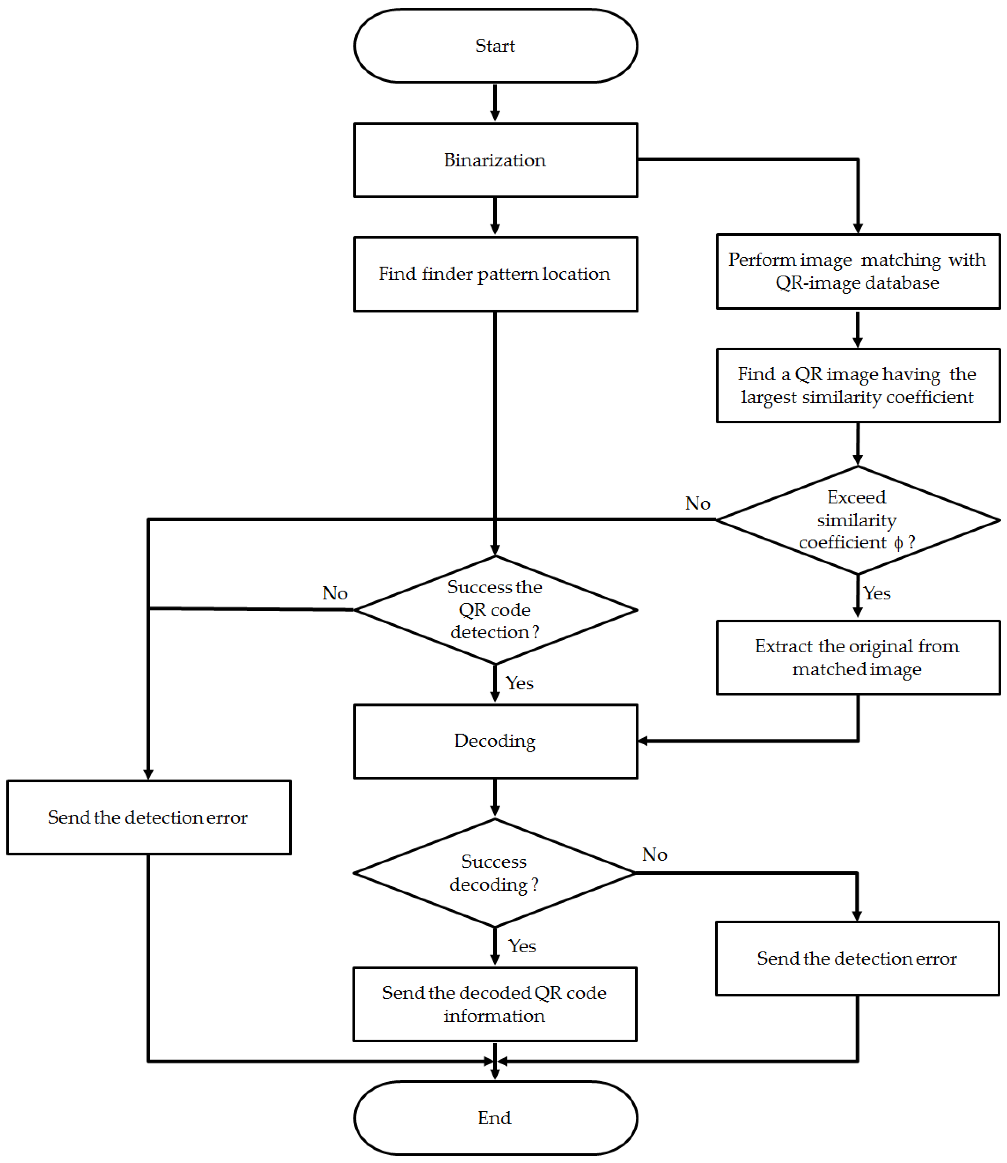
The specific operation method is as follows. As in Figure 12, when a QR code scanned by the user is received, the image’s noise needs to be removed from the binarization. By extracting QR codes in certain sphere, the method checks for similarity by comparing with QR code images in a database. Then, the image that has the largest similarity must be found and a check is done as to whether the value exceeds a similarity threshold value (φ).
If the similarity exceeds the threshold value, decoding using the original image corresponding to the image found in the database is conducted and the result is then transmitted to the user. On the contrary, if a queried image has a similarity lower than the threshold value, then the system transmits a recognition failure message.
The proposed recognition method has value for making QR codes recognizable in a range of scanning angles the existing method cannot recognize. However, when a code is recognized not when a scanned image exceeds a certain angle but when using a recognition method that proposes the front of the image, it has a configuration that provides a lower level of function than the existing method. To solve this problem, a recognition method that combines the existing recognition method and the proposed recognition method can be used.
Figure 13 shows a composition that combines the existing recognition method and the proposed recognition method. When it receives a QR code scanned image from the user, it conducts recognition practically by extracting QR codes from binarization. By using the existing method, it can recognize the finder pattern and by using the proposed recognition method, it checks similarity against entries in a database. The two procedures are conducted simultaneously and when one of the two succeeds in recognition, decoding is performed and the result is transmitted to the user. If both recognition methods fail, the system sends a recognition failure message to the user; when it fails during the decoding procedure, it sends a decoding error message to the user. Through using this combined method, QR codes taken from the front are recognized using the existing recognition method and QR codes scanned in excess of a certain angle are recognized through the proposed recognition method. Thereby, it can provide an improved recognition ratio by solving the problem of recognition at an angle and can overcome the challenge of horizontal angle image recognition, which was the limitation of the proposed method, by using the existing method.
As the number of QR codes increases and more images are saved in the database, there is a drastic increase in the workload of checking overall image similarity.
Thus, this is a suitable method when there are many devices capable of operation so that distributed operation is possible. In particular, it is the suitable for application as the proposed orchestration system’s user service.
4. Performance Evaluation and Analysis
We have established a test bed based on the Bluetooth-beacon-based mesh network mentioned earlier and Docker virtualization technology to evaluate and analyze the proposed network function orchestration system. This section explains the structure of the established test bed and analyzes the result of the evaluation.
4.1. Test Bed Based on the Proposed System
This paper has established a test bed based on open-source software using the Raspberry Pi as a network device for the proposed system. Before we conducted the evaluation, we installed the required packages through the Internet for a total of five Raspberry Pis to set the mesh network installation method and Docker-based cluster method. In addition, to automatically set the network, we used one of the Raspberry Pis as the master node and the others as member nodes.
Additionally, all Raspberry Pis were set in a Docker-based mobile cloud structure as explained in Section 3. In other words, we set the system to enable Docker swarm usage through separately set master and member nodes by setting an environment where a custom OS based on a modified Raspberry Pi OS can be used for Docker [23].
Each node can be explained through matrix 2. First, each node was equipped with a BLE dongle to receive Bluetooth beacon packets and an interface card for wireless LAN was set to establish the mesh network. One additional interface was set for the master node, which had the host name of node-01 to run Hostpad through a demon to allow users to have access [24]. This wireless access point was used to communicate with the maser node to conduct the evaluation.
4.2. Efficiency Evaluation Result
This section will discuss the method and results of the efficiency evaluation in the established test bed, which was set by the method explained in Section 3 and the cloud system. All nodes were created by the proposed mesh network system and the mesh network control module was shut down when all nodes were connected, while one of them was set as the master node for additional evaluation. Therefore, only five Raspberry Pis remained in the network and the evaluation was done while the network was set independently, separately from the Internet. The evaluation result for analyzing potential service availability according to the transfer of data between the master node and member nodes and the virtual network function recovery achieved by the monitoring module are explained below. In addition, the virtualized QR code identification program’s database was used for evaluation to test the proposed network function orchestration system’s network device information. In order to compare the improvement, we tested QR code identification using the image-matching method. Table 2 shows information on the detailed network device of the test bed.
4.2.1. Service Availability Testing of the Proposed Orchestration System
As proposed earlier, the result of the test of each node’s CPU usage with the monitoring module and container clustering is as follows. The test was conducted by the master node’s cluster service control module while setting many containers at a specific node to examine the increase in CPU usage above a critical value.
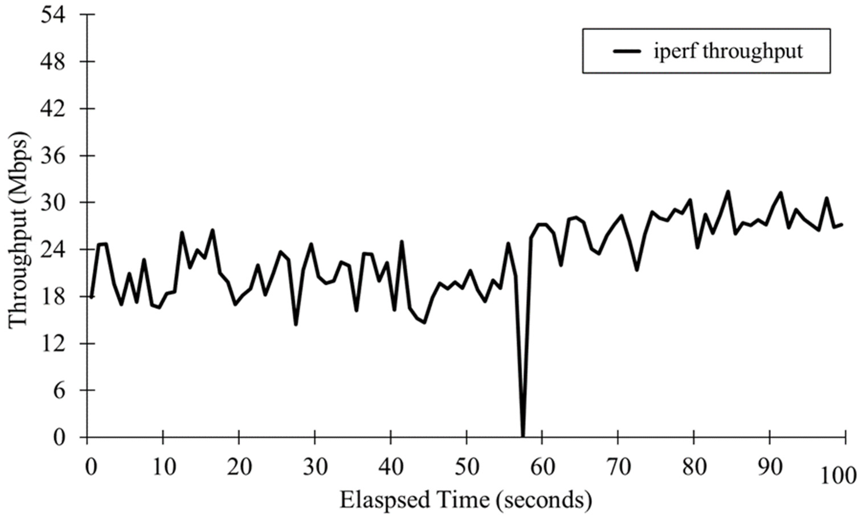
In order to check the continuity of service, Iperf was used to test the capability of the wireless link by checking the spectrum [25]. Figure 14 and Figure 15 show the results of the test conducted at the same time. Iperf continuously sent TCP packets from the client to the server to check the spectrum. This continuity helped to evaluate the potential service availability and this can be replaced by network function, which constantly sends status information as in the Simple Network Management Protocol (SNMP).
As seen in Figure 14, at 56 min, node-02’s CPU usage increased above the critical value. After this, the Iperf client container was moved from node-02 to node-04, which had the lowest CPU usage. Node-02, which sent excessive data to the master node, was shut down four seconds after it finished sending its message.
In Figure 15, the spectrum shows when the user used Iperf and this shows that the connection to the container was shut down and recovered when the container was moving between nodes.
This result shows that each node was able to send its CPU usage above the critical value to the master node through messaging and it was also shown that the exceeding amount of CPU usage was moved to the lowest container node. With the proposed method, constant messaging and monitoring was possible. In addition, the user was able to receive constant service without it being shut down thanks to container movement.
From the network point of view, a user’s Iperf server can be checked and monitored by an SNMP manager while an Iperf client can be seen through the SNMP agent. Similarly, if we were to analyze this from a user service point of view, this can provide constant support to service users in applications such as constant video streaming.
4.2.2. QR Code Recognition Testing of the Proposed Orchestration System
The evaluation of the proposed cloud structure method of QR code identification was done using the test bed explained previously. While the previous evaluation was done using network function, this identification method was done as a means of user service evaluation. Before discussing the detailed disposition of the service as a user service, the comparison between QR code identification and the previous identification should be made to establish bases on which to evaluate user service.
An environment had to be created so that QR code image identification could be compared with previous means of identification. In order to use the image-matching method, 10 QR sample images were photographed from 15 different angles from 0° to 70° at 5°-intervals, as shown in Figure 16 and each image had a width × height of 6.2 cm × 6.0 cm. Each code was photographed from 15 cm away using a smart phone camera and saved after being binary-encoded. The smartphone used for the test was a Nexus 4, which had an 8.0-megapixel digital camera.
Before the evaluation, in order to prove that the proposed method has a wider identification angle compared to the previous one, verification was done to check that the test was conducted under the same conditions. The verification was done with a QR code identification application available on the market to check how the identification of the QR01 code, which had an angle of 0°–70°, was done at different angles. The applications used were the Naver app (Naver) and Zxing’s Barcode Scanner app [26,27]. The results of the test are shown in Table 3.
When the Naver application was used, the application was able to identify the code from an angle of 35° at a 15-cm distance but was not able to identify the code at a 40° angle. The Barcode Scanner application was able to identify a code at a 40° angle at the same distance but was not able to identify the code at a 45° angle. This shows that the application using the previously explained finer pattern method has some weakness in handling images taken at different angles.
On the other hand, the proposed method went through similarity testing to verify whether it was able to identify images at angles of 45° or more. For the test, we used a 60° QR01 code with 150 sample QR images and conducted a similarity comparison to determine whether the proposed method was able to identify the image. The test was done to examine whether the QR01 code captured at different angles had similarity to the 60° image to investigate whether there was a high rate of similarity with other sample QR codes captured at 60°. As shown in Figure 17, QR01’s 60° image showed a critical value of above 90%. This method was able to identify previously unidentified images and was able to improve the identification rate.
The proposed virtual network orchestration system has the special characteristic of sharing a network service system to set the service. The previous 150 QR code images were sent to different nodes connected to the database to test performance.
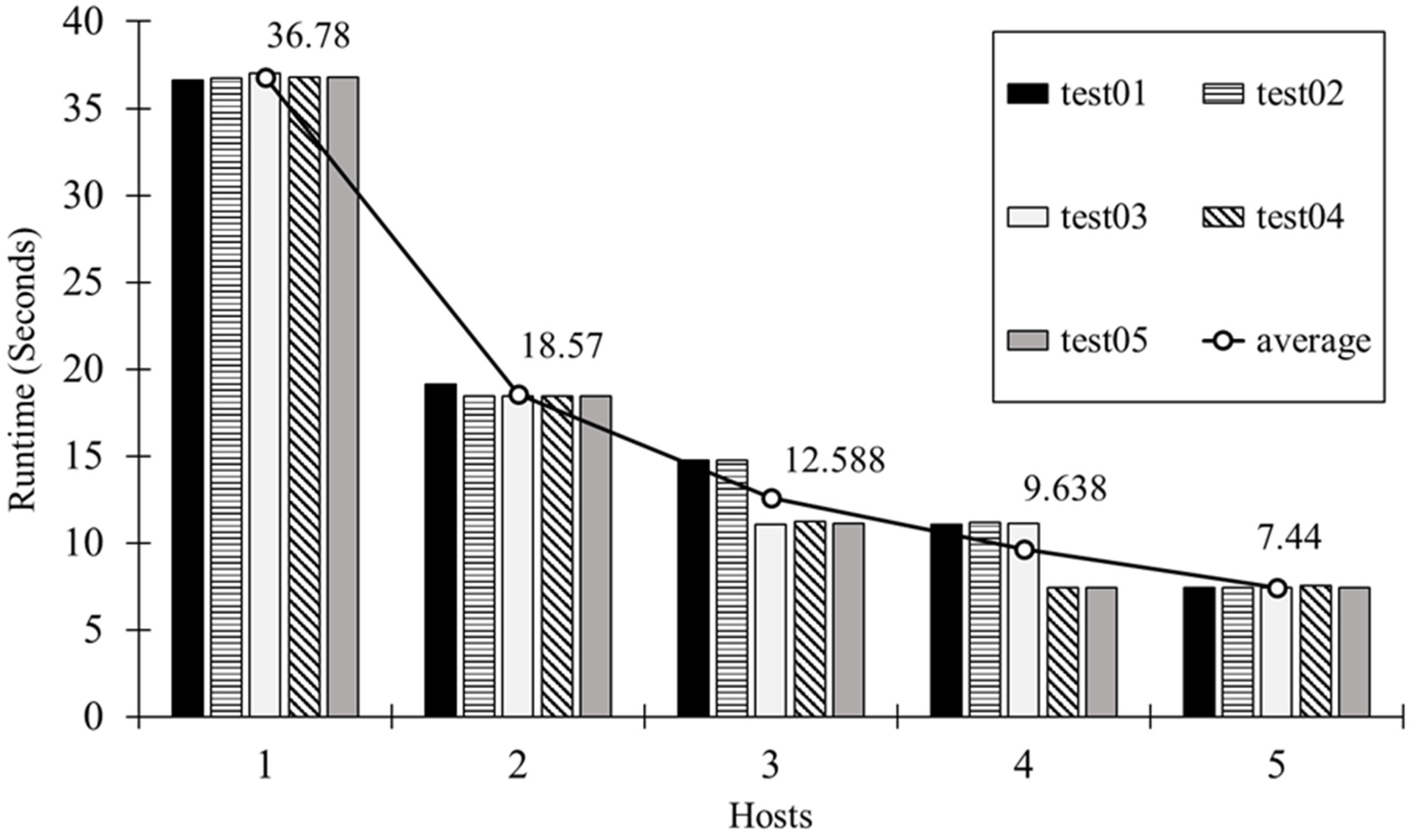
For performance testing, the test was done to check the identification speed when the image database was set at different nodes for the image-matching process. The test was conducted while using one to five nodes in a database and was conducted five times for different numbers of nodes and the average rate was analyzed. The time required for the client to send and receive an image to and from the server as well from the server to different nodes for decoding was not included in the test.
The results of the test are shown in Figure 18. 36.78 s were required to compare one QR code to 150 images in the database one by one for similarity testing. When two databases were used to match the image, 18.57 s were required, which was half the time required when using one database. When three databases were used, the speed was increased by three times and when four databases were used, the time was increased by four times compared to when one database was used. When five databases were used, the time required for processing was reduced to 20%. This shows that the required time decreased as 1/N (number of databases used).
Through this performance test, the proposed QR code identification method supports wider scanning angles and shows faster QR code identification when the environment is set for the distributed image process.
Likewise, the orchestration system proposed in this paper was tested in terms of virtual network function as well as QR code identification service in order to verify the distributed process method. The proposed orchestration system can set different network device connections based on different environments and we were able to verify that this system can provide better service for users.
5. Conclusions and Further Research
This paper proposed a network orchestration system based on network virtualization technology. Actual performance testing used open-source hardware as a network and set Docker-based virtual network function. This showed maintenance of service availability by repositioning network function based on the CPU usage of the nodes. Moreover, in order to solve the restart problem when the network is reset, this paper proposed a faster way of recovering to the environment before the reset. This improved the container structure, which, unlike virtual machines, could not provide continued service and allowed the container to enjoy the same continuity in the system.
Furthermore, this paper proposed a network orchestration system user service that improved a two-dimensional QR code identification method and tested its performance. Firstly, the proposed QR code identification method is different from the existing method as it conducts an image-matching process which facilitates the advantages of using a massive number of images, such as in a cloud system. A Nexus 4 smart phone was used to test and compare performance with those of existing applications. Better performance for the proposed method was observed, as it can identify images at a maximum scanning angle of 60° while the existing system allows a maximum angle of only 40°. Under the proposed system environment, an image database was set using different databases based on network device status information to improve processing speed. This showed that the information on a number of machines was used to set separate databases, allowing the best network conditions for using network status information to conduct network orchestration.
In conclusion, as mobile data traffic has significantly improved, expanding the scale of networks and their complexity and making research on 5G networks possible, the proposed method provides advantages for network orchestration systems in devising a 5G mobile access network with low cost using cheaper machines and open-source networks. Moreover, it provides advantages in terms of constant network provision.
In the future, this research could be used as a basis for measures to establish the most optimal virtual network function using network status information based on different requirements. In addition, with its low operating/development cost, such a system is expected to contribute to active establishment of computing environments for less economically developed countries.
Acknowledgments
This research was supported by Basic Science Research Program through the National Research Foundation of Korea (NRF) funded by the Ministry of Education (NRF-2015R1D1A1A01059147).
Author Contributions
All the authors contributed equally to this work. All authors read and approved the final manuscript.
Conflicts of Interest
The authors declare no conflict of interest.
References
- Index, C.V.N. Global Mobile Data Traffic Forecast Update 2014–2019. White Paper c11-520862. Available online: http://www.cisco.com/c/en/us/solutions/collateral/serviceprovider/visual-networking-index-vni/white_paper_c11-520862.html (accessed on 17 June 2017).
- Ericsson, A. Ericsson mobility report: On the pulse of the networked society. Ericsson Sweden Tech. Rep. 2015, EAB-14, 61078. [Google Scholar]
- Doetsch, U.; Droste, H.; Roos, A.; Rosowski, T.; Zimmermann, G.; Agyapong, P.; Fonseca, N.; Lindqvist, I.D.S.; Eriksson, H.; Tullberg, H. Deliverable d6. 4 Final Report on Architecture. Available online: https://www.metis2020.com/wp-content/uploads/deliverables/METIS_D6.4_v2.pdf (accessed on 7 November 2017).
- Kim, M.; Park, J.-H.; Na, M.; Jo, S. 5G Mobile Communications Development Direction. KICS Inf. Commun. Mag. Open Lect. Ser. 2015, 32–39, 46–54. [Google Scholar]
- OPNFV Arno Release. Available online: http://www.opnfv.org/arno (accessed on 17 June 2017).
- Chiaraviglio, L.; Amorosi, L.; Cartolano, S.; Blefari-Melazzi, N.; Dell’Olmo, P.; Shojafar, M.; Salsano, S. Optimal superfluid management of 5 g networks. In Proceedings of the 2017 IEEE Conference on Network Softwarization (NetSoft), Bologna, Italy, 3–7 July 2017; pp. 1–9. [Google Scholar]
- Marotta, A.; D’Andreagiovanni, F.; Kassler, A.; Zola, E. On the energy cost of robustness for green virtual network function placement in 5g virtualized infrastructures. Comput. Netw. 2017, 125, 64–75. [Google Scholar] [CrossRef]
- Marotta, A.; Zola, E.; D’Andreagiovanni, F.; Kassler, A. A fast robust optimization-based heuristic for the deployment of green virtual network functions. J. Netw. Comput. Appl. 2017, 95, 42–53. [Google Scholar] [CrossRef]
- Salsano, S.; Chiaraviglio, L.; Blefari-Melazzi, N.; Parada, C.; Fontes, F.; Mekuria, R.; Griffioen, D. Toward superfluid deployment of virtual functions: Exploiting mobile edge computing for video streaming. In Proceedings of the 2017 29th International Teletraffic Congress (ITC 29), Genoa, Italy, 4–8 September 2017; pp. 48–53. [Google Scholar]
- Chromium Operating System. Available online: https://www.chromium.org/chromium-os (accessed on 17 June 2017).
- Carrega, A.; Repetto, M.; Gouvas, P.; Zafeiropoulos, A. A middleware for mobile edge computing. IEEE Cloud Comput. 2017, 4, 26–37. [Google Scholar] [CrossRef]
- Docker Web Site. Available online: http://www.docker.com (accessed on 17 June 2017).
- Raspberry Pi Web Site. Available online: http://www.raspberrypi.org (accessed on 17 June 2017).
- Mozumder, A.H.; Acharjee, T.; Roy, S. Scalability performance analysis of batman and hwmp protocols in wireless mesh networks using ns-3. In Proceedings of the 2014 International Conference on Green Computing Communication and Electrical Engineering (ICGCCEE), Coimbatore, India, 6–8 March 2014; pp. 1–5. [Google Scholar]
- Jiang, Z.-Y.; Ma, J.-F.; Jing, X. Enhancing traffic capacity of scale-free networks by employing hybrid routing strategy. Phys. A Stat. Mech. Its Appl. 2015, 422, 181–186. [Google Scholar] [CrossRef]
- Singh, K.; Verma, A.K. Experimental analysis of aodv, dsdv and olsr routing protocol for flying adhoc networks (fanets), Electrical. In Proceedings of the 2015 IEEE International Conference on Computer and Communication Technologies (ICECCT), Tamilnadu, India, 5–7 March 2015; pp. 1–4. [Google Scholar]
- B.A.T.M.A.N. Web Site. Available online: http://www.open-mesh.org (accessed on 17 June 2017).
- Docker Swarm Web Site. Available online: http://docs.docker.com/swarm/ (accessed on 17 June 2017).
- QR Code Web Site. Available online: http://www.qrcode.com (accessed on 17 June 2017).
- Qian, X.; Cho, D.-S.; Kim, M.-H. Qr code recognition mobile system using dsp based qr decoder. In Proceedings of the 7th International Conference on Multimedia Information Technology and Applications (MITA), Tashkent, Uzbekistan, 30 June–2 July 2011; pp. 294–297. [Google Scholar]
- Ohbuchi, E.; Hanaizumi, H.; Hock, L.A. Barcode readers using the camera device in mobile phones. In Proceedings of the 2004 International Conference on Cyberworlds, Washington, DC, USA, 18–20 November 2004; pp. 260–265. [Google Scholar]
- Gu, Y.; Zhang, W. Qr code recognition based on image processing. In Proceedings of the 2011 International Conference on Information Science and Technology (ICIST), Nanjing, China, 26–28 March 2011; pp. 733–736. [Google Scholar]
- Hypriot OS Web Site. Available online: http://blog.hypriot.com (accessed on 17 June 2017).
- Hostapd Web Site. Available online: http://hostap.epitest.fi/hostapd (accessed on 17 June 2017).
- Iperf Official Web Site, Iperf: The TCP/UDP Bandwidth Measurement Tool. Available online: http://iperf.fr/ (accessed on 17 June 2017).
- Naver Web Site. Available online: http://qr.naver.com (accessed on 17 June 2017).
- Zxing Web Site. Available online: http://code.google.com/p/zxing (accessed on 17 June 2017).
Figure 1.
System Model for the Virtualized Network Function oriented 5G Mobile Network.
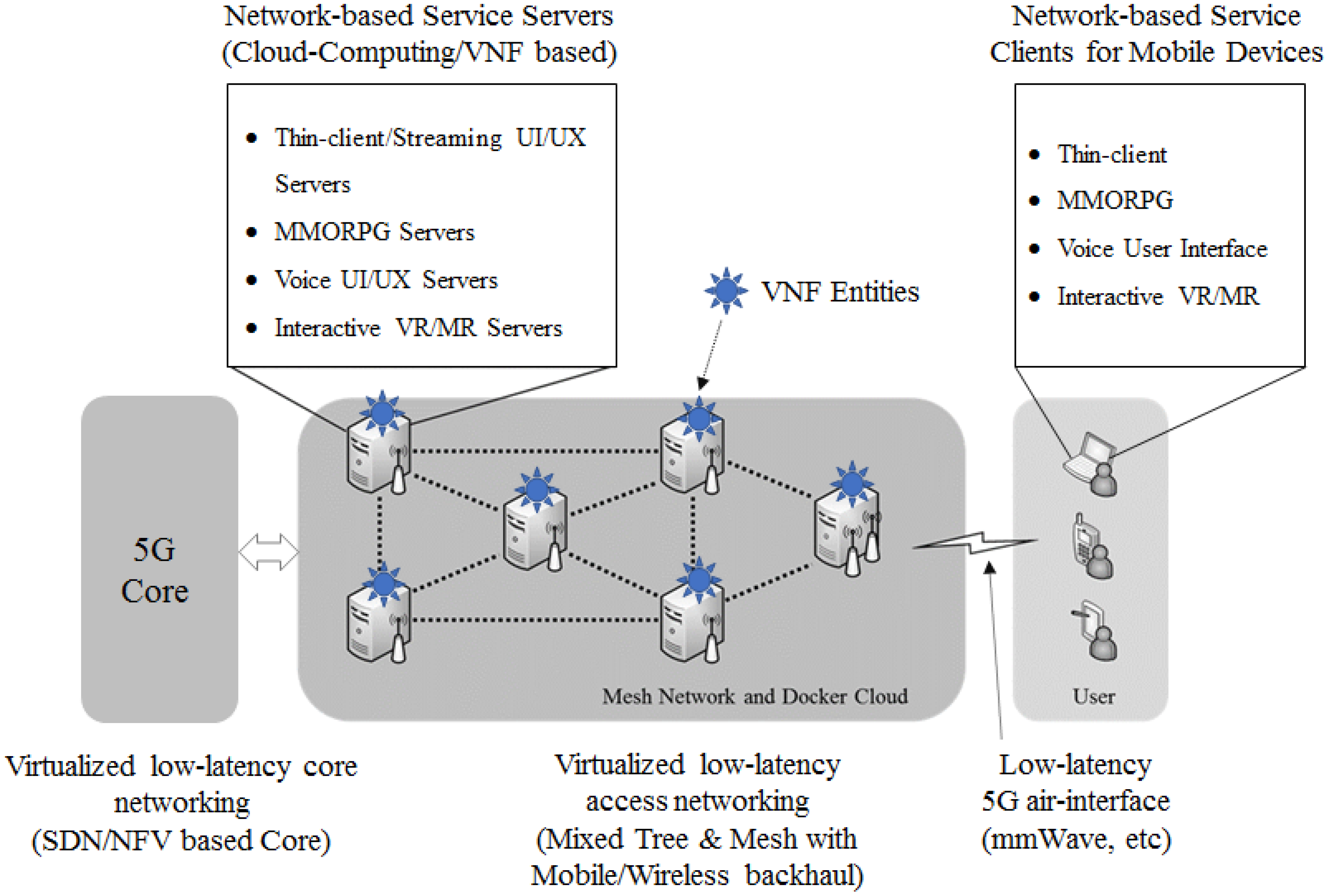
Figure 2.
The architecture of a virtual machine and a docker.

Figure 3.
Internal structure of a network device applying a docker swarm.
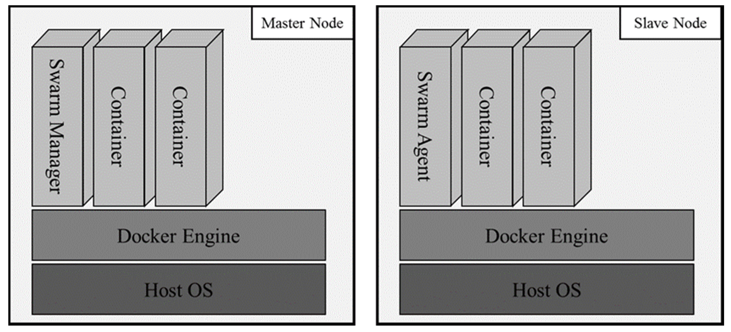
Figure 4.
The structure of a QR code.

Figure 5.
Architecture of the applied proposed networking method and device internal structure.
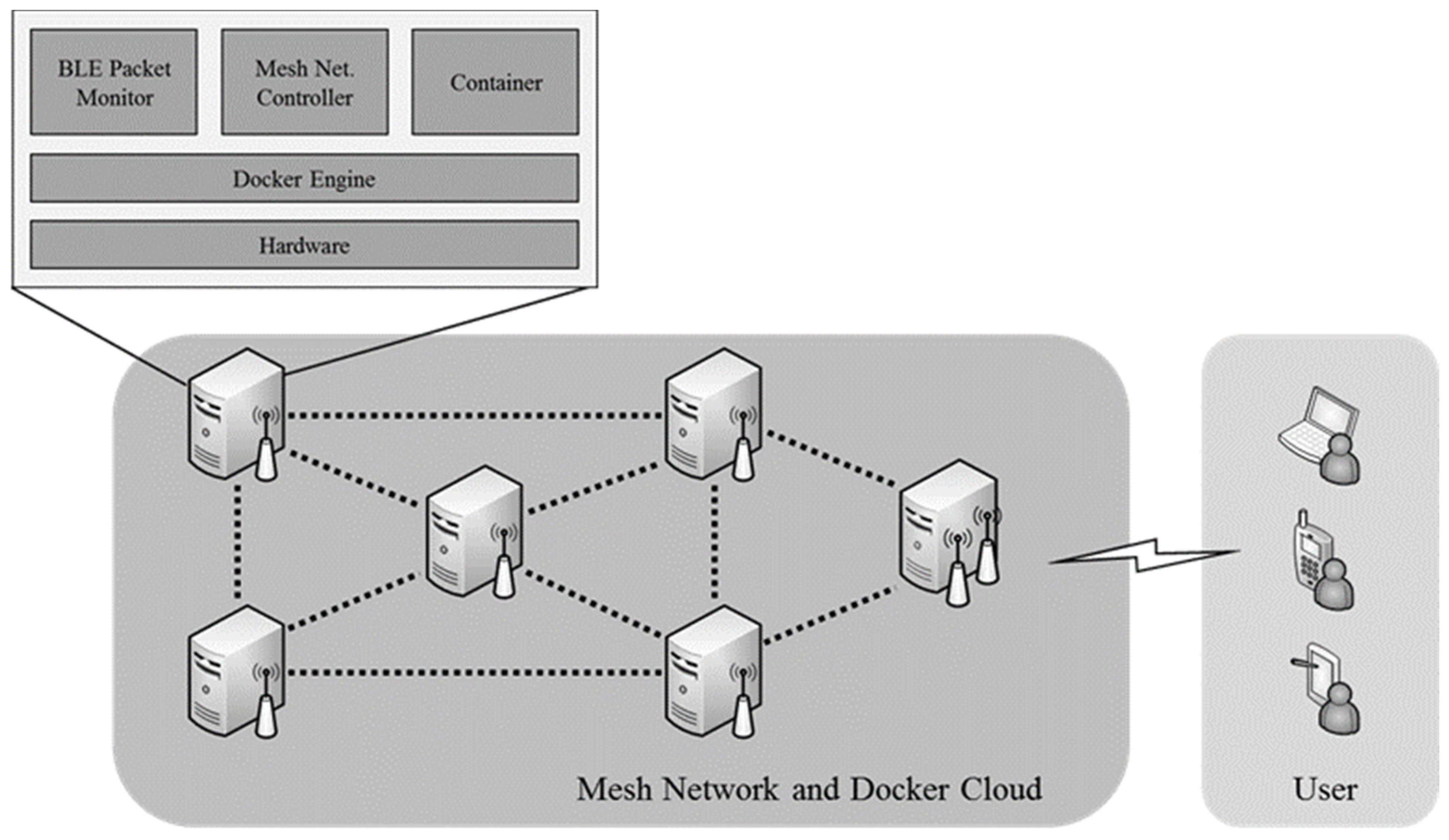
Figure 6.
Master node’s mesh net control module operational process.
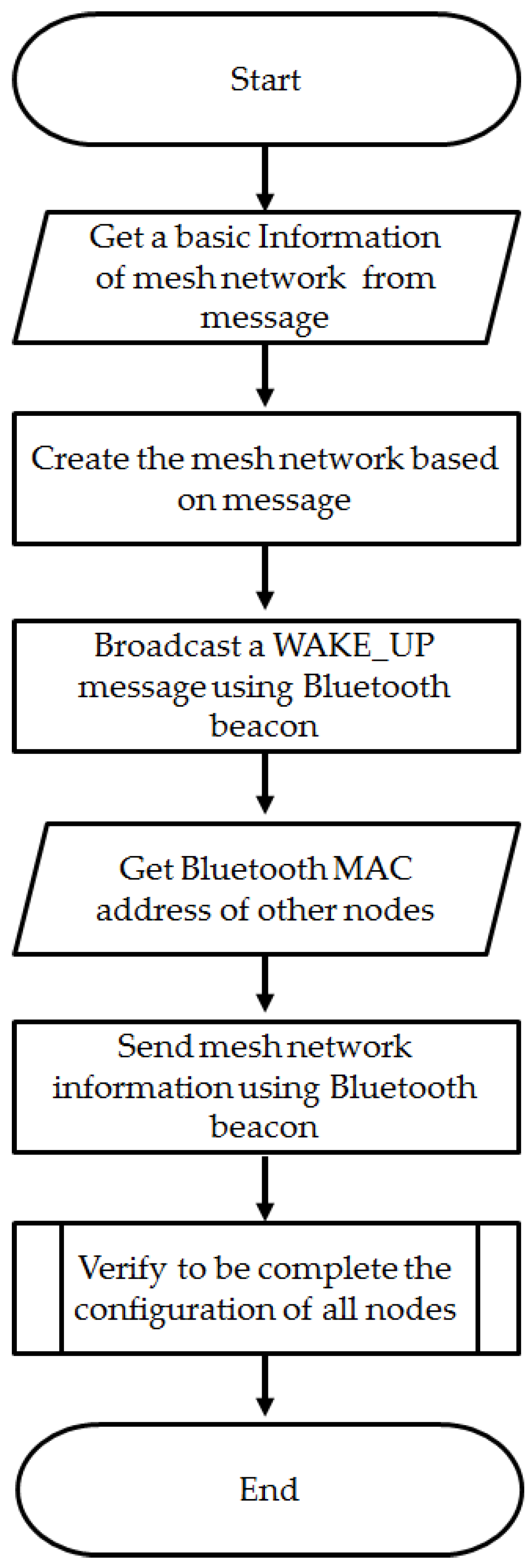
Figure 7.
Member node’s mesh net control module operational process.

Figure 8.
Mesh net controller mutual recognition and information exchange procedure.

Figure 9.
Internal structure of the master node.

Figure 10.
Internal structure of a member node.

Figure 11.
VNF recovery procedure in the proposed orchestration system.
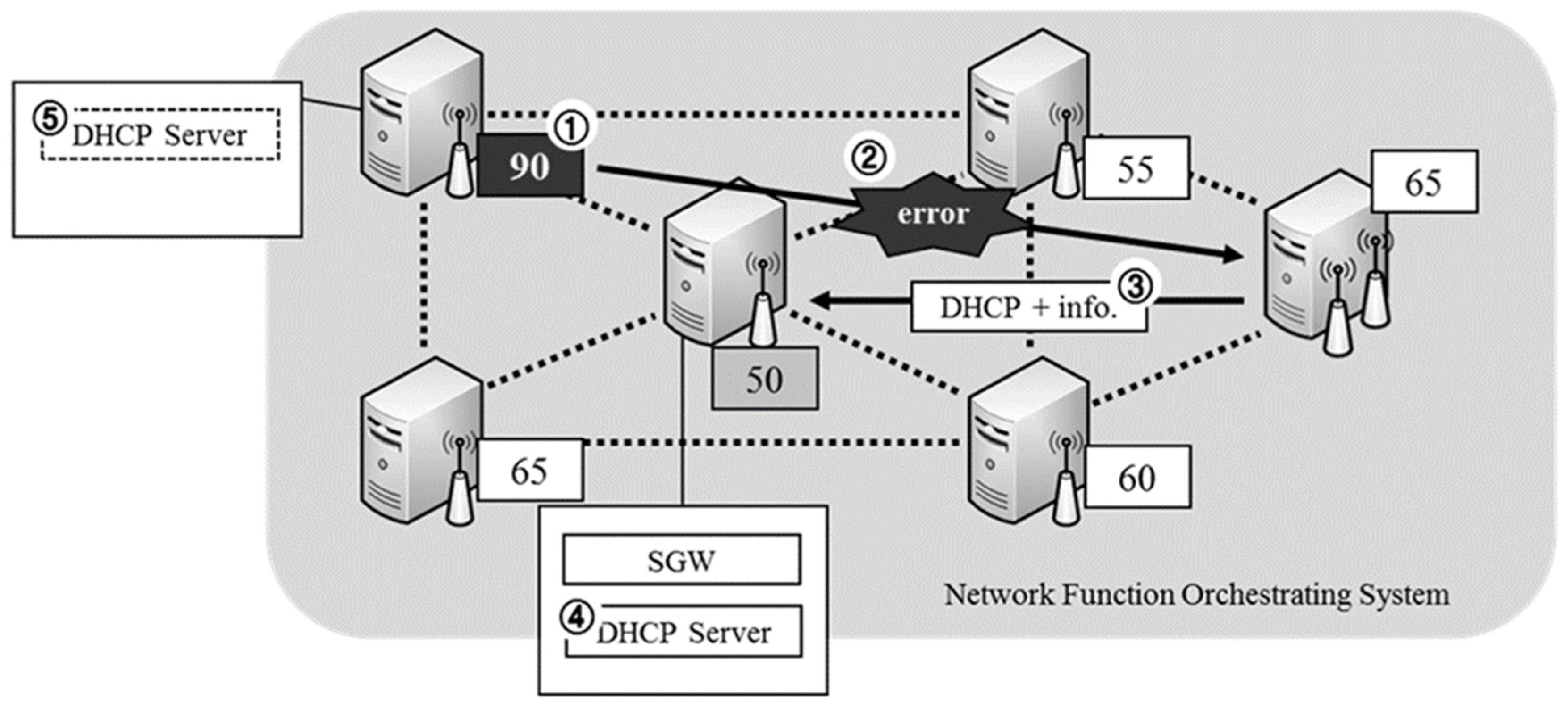
Figure 12.
Operation process of the proposed QR code recognition.

Figure 13.
Operation process based on combining the existing and proposed methods.

Figure 14.
Result of CPU usage for each node in the proposed method.
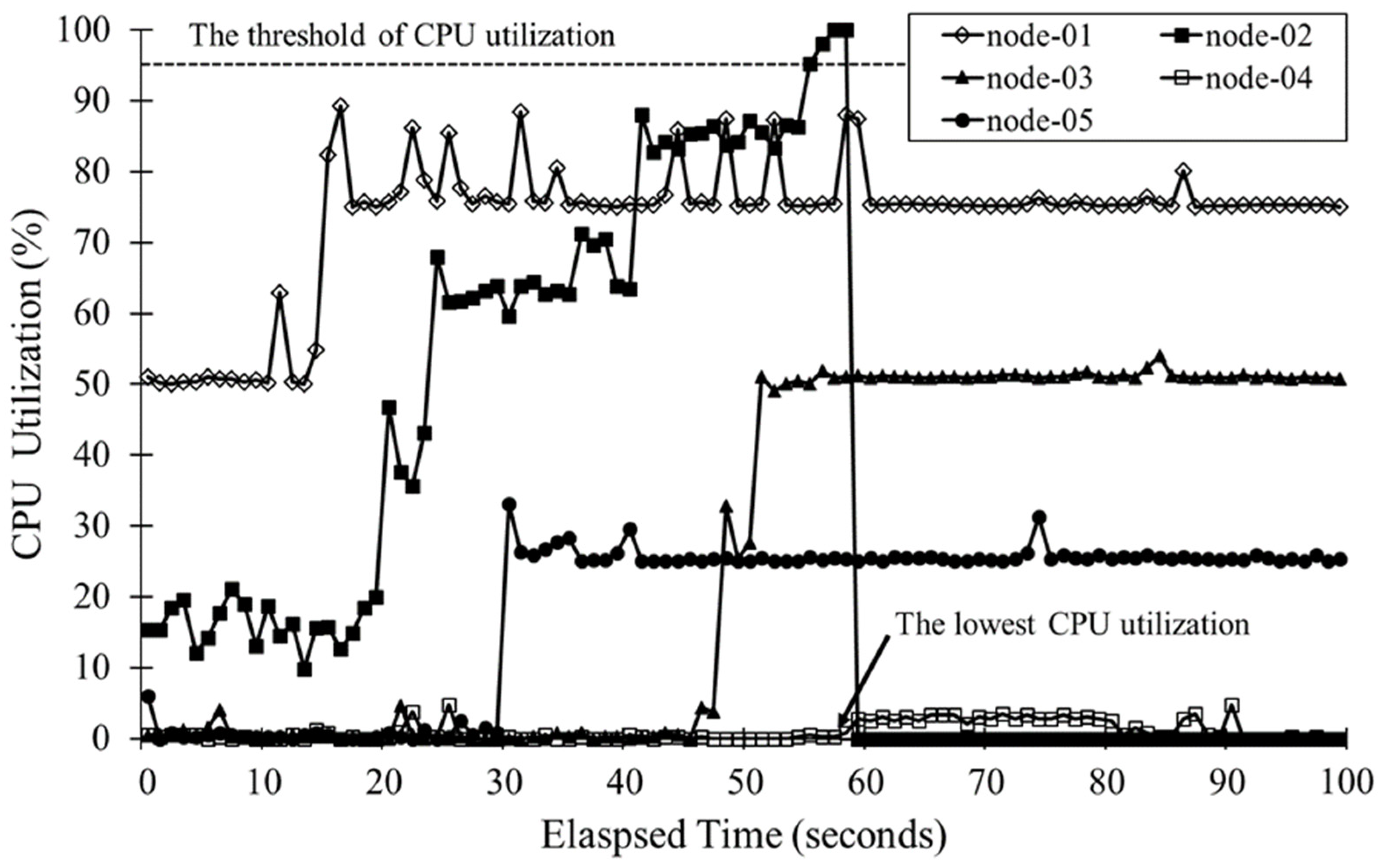
Figure 15.
Result of wireless link bandwidth test to verify the proposed network

Figure 16.
Sample QR codes for testing the proposed QR identification method.
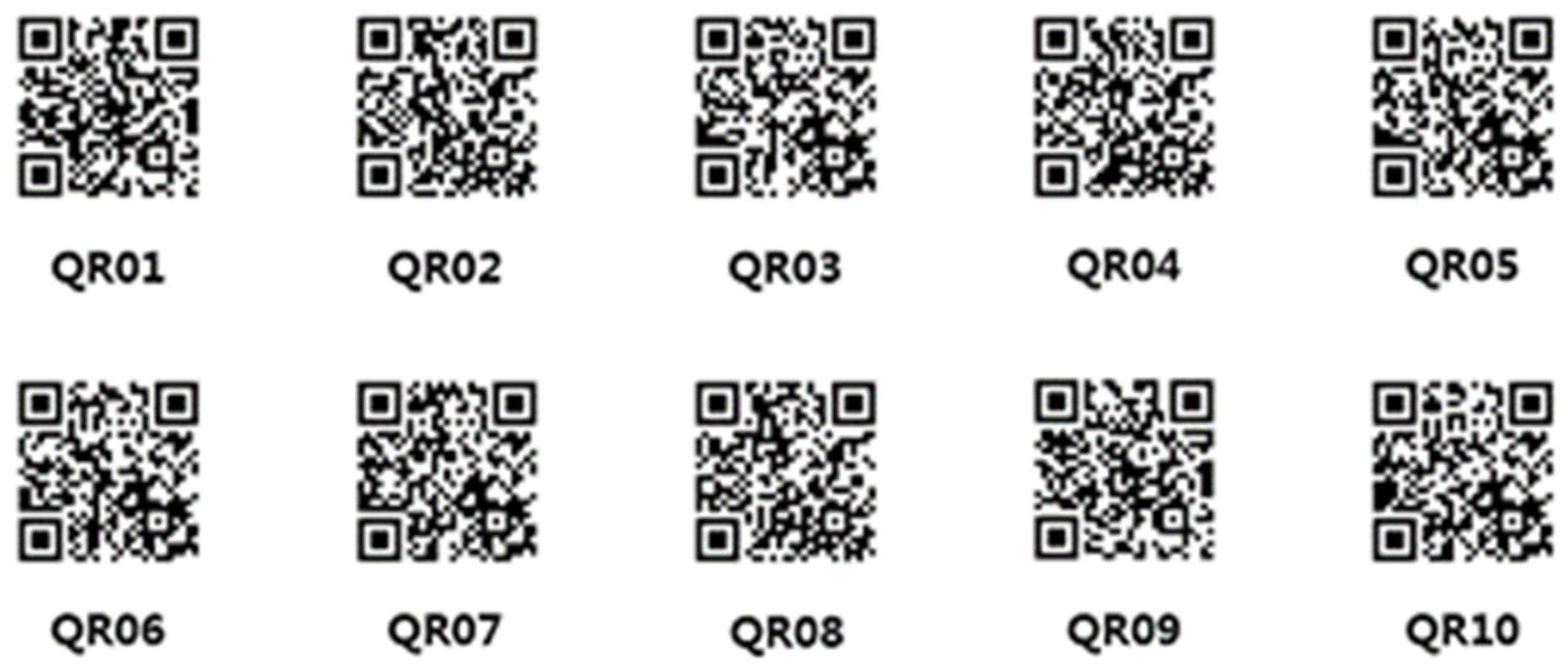
Figure 17.
QR code similarity graph applied for the proposed recognition method.
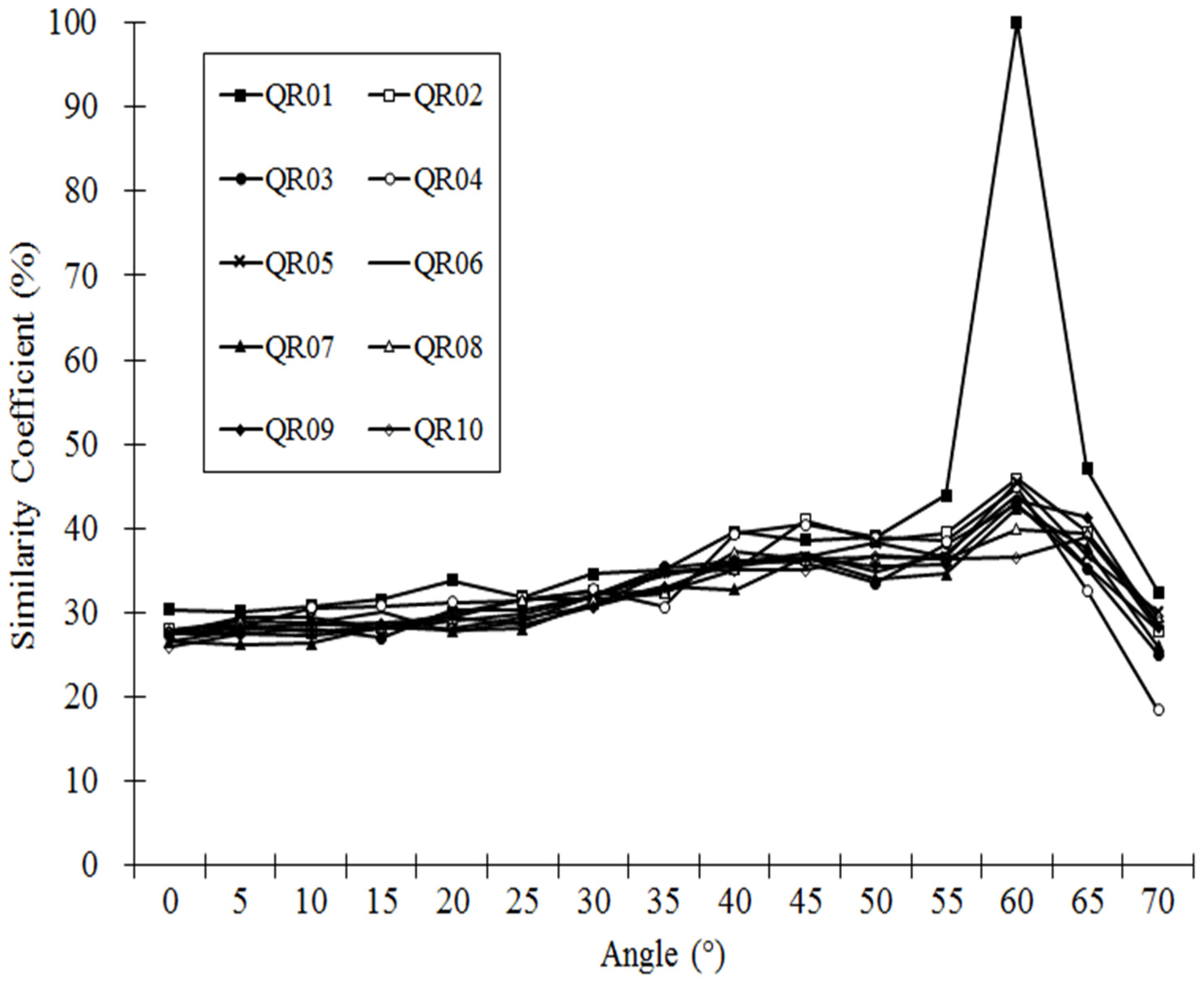
Figure 18.
Test of QR code identification for different numbers of databases used.

Table 1.
Docker swarm API information.
| Master | Containers | Total Number of Containers in Cluster |
| Nodes | Total Number of Nodes in Cluster | |
| Host (Member) | Name | Host Name |
| IP | IP Address of Host | |
| Containers | Number of Containers in Host | |
| CPUs | Number of CPU cores | |
| Memory | Memory Capacity |
Table 2.
Detailed network device information for the test bed.
| SoC | Broadcom BCM2836 |
| CPU | 900 MHz ARM Cortex-A7 Quad-core |
| RAM | 1GB LPDDR2 |
| OS | Hypriot OS |
| Network Interface Card | NEXT-301N USB—2.4GHz |
| Bluetooth | NEXT-204BT CSR4.0 |
Table 3.
Maximum angles for the Nexus 4’s QR code identification using existing applications.
| APPD | Naver | Barcode Scanner | |
|---|---|---|---|
| Distance | |||
| 15 cm | 35° | 40° | |
© 2017 by the authors. Licensee MDPI, Basel, Switzerland. This article is an open access article distributed under the terms and conditions of the Creative Commons Attribution (CC BY) license (http://creativecommons.org/licenses/by/4.0/).
Share and Cite
MDPI and ACS Style
Ahn, M.; Lee, S.; Lee, S. Virtualized Network Function Orchestration System and Experimental Network Based QR Recognition for a 5G Mobile Access Network. Symmetry 2017, 9, 300. https://doi.org/10.3390/sym9120300
AMA Style
Ahn M, Lee S, Lee S. Virtualized Network Function Orchestration System and Experimental Network Based QR Recognition for a 5G Mobile Access Network. Symmetry. 2017; 9(12):300. https://doi.org/10.3390/sym9120300
Chicago/Turabian StyleAhn, Misun, SeungGwan Lee, and Sungwon Lee. 2017. "Virtualized Network Function Orchestration System and Experimental Network Based QR Recognition for a 5G Mobile Access Network" Symmetry 9, no. 12: 300. https://doi.org/10.3390/sym9120300
Note that from the first issue of 2016, this journal uses article numbers instead of page numbers. See further details here.