Enhanced Joint and Separable Reversible Data Hiding in Encrypted Images with High Payload


School of Electrical Engineering, University of Ulsan, Ulsan 44610, Korea
*
Author to whom correspondence should be addressed.
Symmetry 2017, 9(4), 50; https://doi.org/10.3390/sym9040050
Submission received: 14 February 2017
/
Revised: 10 March 2017
/
Accepted: 23 March 2017
/
Published: 28 March 2017
(This article belongs to the Special Issue Symmetry in Secure Cyber World)
Abstract
:Recently, much attention has been paid to reversible data hiding (RDH) in encrypted images, since it preserves the data that the original image can be perfectly recovered after data extraction while protecting the confidentiality of image content. In this paper, we propose joint and separable RDH techniques using an improved embedding pattern and a new measurement function in encrypted images with a high payload. The first problem in recent joint data hiding is that the encrypted image is divided into blocks, and the spatial correlation in the block cannot fully reflect the smoothness of a natural image. The second problem is that half embedding is used to embed data and the prediction error is exploited to calculate the smoothness, which also fails to give good performance. To solve these problems, we divide the encrypted image into four sets, instead of blocks; the actual value of pixels is considered, rather than an estimated value, and the absolute difference between neighboring pixels is used in preference to prediction error to calculate the smoothness. Therefore, it is possible to use spatial correlation of the natural image perfectly. The experimental results show that the proposed joint and separable methods offer better performance over other works.
1. Introduction
With the rapid growth of internet technology, it has become very easy to download media such as pictures, images, and audio or video files. This makes media data not only easy to transmit but also easy to copy and distribute. Therefore, pirates can easily record and distribute copyright-protected material without paying the appropriate compensation to the owner. Thus, a legal issue arises such that some media need to be protected against unauthorized use or operations. Data hiding and encryption are two effective and prevalent means of privacy protection and secret communication.
Data hiding has attracted considerable research interest in recent years [1,2,3]. By this technique, secret data can be embedded into a cover medium, and later the embedded data can be extracted from the marked medium for various purposes. Hong et al. [1] proposed a novel data-embedding method using adaptive pixel pair matching. Hussain et al. [2] introduced a hybrid data hiding method combining the right-most digit replacement (RMDR) with an adaptive least significant bit (ALSB) for digital images. Hong et al. [3] proposed a new data hiding technique for absolute moment block truncation coding (AMBTC) compressed image based on quantization level modification. However, for most data hiding systems, during the data hiding operation the cover medium has been distorted and hence, after data extraction, the cover medium cannot be recovered to its original state. Such permanent distortion is unacceptable and the exact recovery of the original cover medium is prerequisite in some sensitive applications like medical, defense, legal matters, artwork, and so on. To solve this problem, reversible data hiding (RDH), also known as lossless or invertible data hiding, is proposed to exactly recover both the hidden data and the cover medium. Explicitly, with the RDH, not only the hidden data but also the cover medium can be exactly recovered from the marked medium.
Several RDH techniques have been introduced [4,5,6,7,8,9,10]. In 2003, Tian [4] proposed a reversible data hiding method using the difference expansion technique, where one bit is embedded into the difference of two successive pixels. In 2006, Ni et al. [5] introduced a novel RDH system based on histogram shifting by utilizing the minimum and maximum points of the image histogram; data are concealed by shifting the histogram. In 2007, Thodi and Rodriguez [6] proposed a different technique by expanding the prediction errors. In 2010, Luo et al. [7] presented a new reversible data hiding process by adopting an additive interpolation error expansion technique, which provides very small falsification and a comparatively high capability. Moreover, to improve performance, many techniques have been proposed for typical reversible data hiding approaches [8,9,10].
In some applications of data hiding, the embedded carriers are further encrypted to prevent the carrier from being analyzed to expose the existence of the embedding [11,12]. In 2007, Lian et al. [11] proposed a video encryption and watermarking scheme based on H.264, the advanced video coding (AVC) codec, where media data are encrypted and partially watermarked. In 2010, Cancellaro et al. [12] presented a commutative watermarking and ciphering scheme where a watermarked image is further encrypted to increase the security of the system.
Most of the existing reversible data-hiding systems are only suitable for unencrypted covers. However, for maintaining confidentiality or protecting privacy, in many fields—like medicine, the military, and the law—a content owner may demand to encrypt the original images. Meanwhile, without knowing the encryption key and the plaintext content, a channel administrator or an inferior assistant may need to insert some additional information within the encrypted images. As an authorized receiver, it is essential that hidden information can be extracted and the original cover can be recovered error-free without any loss or distortion after image decryption and data extraction. Reversible data hiding in encrypted images (RDH-EI) gratifies these requirements.
The existing RDH-EI methods can be classified into two categories: “vacating room before encryption (VRBE)” and “vacating room after encryption (VRAE)”. In VRBE, the content owner creates room for embedding data in the cover image before encryption [13,14]. As VRBE requires the content owner to do an extra preprocessing before content encryption, so this method might be impractical. In this sense, the VRAE method is more practical. In VRAE methods, the original content is encrypted by the content owner, and the data-hider embeds the additional information by modifying a small part of the encrypted data [15,16,17,18,19,20,21,22,23]. The VRAE methods can be further divided into two categories: joint method and separable method.
In joint methods [15,16,17,18,19,20], with an encrypted image containing additional data, a receiver may first decrypt it using the encryption key, and then extract the embedded data and recover the original image from the decrypted image using the data-hiding key. In 2011, Zhang [15] proposed a novel reversible data hiding technique in encrypted images. In 2012, Hong et al. [16] improved Zhang’s technique by using a side match technique. Zhang’s and Hong’s systems were further enhanced with other techniques [17,18]. In these systems, the encrypted image is divided into blocks, and the spatial correlation in the block cannot fully reflect the smoothness of natural images, especially when the block size is small. In 2014, Li et al. [19] introduced a new scheme where a random diffusion strategy is used for embedding and accurate prediction is used to measure the smoothness. In 2014, Wu and Sun [20] proposed a different joint RDH system based on prediction error. However, the smoothness calculation from using prediction error fails to perform well.
Nevertheless, in joint methods, the embedded data can only be extracted before image decryption. In other words, a receiver having a data-hiding key but no encryption key cannot extract any information. Moreover, when the payload is high, it is not possible to get error-free extracted bits with all these joint methods. To overcome these problems, a separable reversible data-hiding scheme is required.
In separable methods [20,21,22,23], with an encrypted image containing additional data, if a receiver has the data-hiding key, he can extract the additional bits from the marked encrypted image directly, while if the receiver has the encryption key, he can decrypt the received data which is similar to the original one. When, the receiver has both the data-hiding and encryption keys, he can extract the additional bits and recover the original image perfectly. However, in [20] prediction error is used for separable method too which causes worse performance. Moreover, in [21] data cannot be extracted precisely and the original image cannot be recovered perfectly especially when the payload is high. Beyond that, many parameters assumed in [21] make it a little complicated for implementation. Qian et al. [22] proposed a novel scheme of RDH in encrypted images using distributed source coding (DSC) where the low-density parity check (LDPC) encoding and source decoding are used which make the system’s complexity much higher. Xiao et al. [23] proposed a separable RDH technique in encrypted images based on pixel value ordering (PVO) where homomorphism encryption is used for image encryption.
To solve the above-mentioned issues in both joint and separable methods, we propose an improved joint and separable RDH technique in this paper. For joint method, the encrypted image is divided into four sets, instead of blocks, and two sets can be used for data hiding. Therefore, the embedding capacity increases. In addition, we consider the actual value of pixels in preference to an estimated value, and exploit the absolute difference between neighboring pixels, rather than prediction error, to calculate fluctuation for both joint and separable method. By avoiding block division and prediction error, we fully use the spatial correlation property of a natural image, which helps to reduce the bit error rate (BER). For this reason, performance of the proposed system is superior to the performance of other systems. Additionally, before hiding the data, we encrypt the information bits to further increase the security of the system.
The rest of this paper is organized as follows. Related work is described in Section 2. Then, the proposed joint and separable data hiding systems are discussed in Section 3 and Section 4, respectively. After that, the experimental results are presented in Section 5. Finally, the conclusion is in Section 6.
2. Related Work
In this section, we explain the important and related results of the referenced papers to be compared with our research. Zhang [15], encrypted the original host image by using an encryption key. The pixels in the original host image are decomposed into bits and a random sequence is determined by an encryption key using standard stream cipher. The exclusive-or results of original bits and pseudo-random bits are calculated to encrypt the original image. Then, the encrypted image is divided into non-overlapping blocks sized s × s, and according to the data-hiding key, each block is divided into two sets, S0 and S1, pseudo-randomly. Each block is capable of carrying one bit. If the bit to be inserted is 0, then the three least significant bits (LSBs) of each pixel in set S0 are flipped. On the other hand, if the bit to be inserted is 1 then the three LSBs of each pixel in set S1 are flipped. Thus, the embedding process is done. For data extraction and image recovery, the receiver first decrypts the embedded encrypted image. Then, the decrypted image is partitioned into non-overlapping blocks sized s × s. According to the data-hiding key, the pixels of each block are divided into two sets, S0 and S1, pseudo-randomly in the same way as before. For each decrypted block, two new blocks, B0 and B1, are obtained. In B0, all three LSBs of each pixel in S0 are flipped, and in B1, all three LSBs of the pixels in S1 are flipped. One of B0 and B1 is the original block, and the other is the three LSBs flipped block. To determine which one is the original block, Zhang [15] proposed a fluctuation function fZ to calculate the smoothness of B0 and B1 as follows:
where p(u,v) ∈ Bc for c = 0, 1.
In [16], Hong et al. ameliorated data the extraction and image recovery part based on Zhang’s method. Firstly, they proposed a new function as (2) where more pixels are considered to reduce the bit error rate.
Secondly, data extraction and image recovery is done according to the descending order of the absolute smoothness difference between two candidate blocks. Finally, side match technique is used to achieve a much lower error rate.
In order to further reduce the error rate, Liao et al. [17] introduced a new more precise function to calculate the fluctuation of each image block. They employed two, three, or four neighboring pixels according to the location of each pixel. Furthermore, the data embedding ratio is also considered in this technique.
In these systems [15,16,17], the encrypted image is divided into blocks and the spatial correlation in the block cannot fully reflect the smoothness of natural images, especially when the block size is small. The constraint and centralization of local pixels will cause unreliability in the fluctuation measurement, which is based on the smoothness of natural images. Therefore, in the proposed work, we thoroughly avoid the idea of block division to reduce the bit error rate.
Based on prediction error, Wu and Sun [20] proposed two RDH techniques: joint and separable. In joint method, they divided the encrypted image into two sets: TQual and TForb, according to the data-hiding key. Then, only pixels in TQual, which are about half of the encrypted image, are used for data embedding. For inserting information in data hiding, pixels in TQual are divided into groups, and each group is composed of m pixels. One bit of information can be embedded in one group. For data extraction and image recovery, the receiver first decrypts the embedded encrypted image. Then, the decrypted image is divided into two sets: TQual and TForb. The pixels in TQual are retrieved and divided into groups, and the d-th group contains m pixels, denoted as P(u,d) for u = 1, 2,…, m. For each pixel, an estimated pixel, PEst(u,d), is calculated by using four neighboring pixels and a flipped pixel, PFlip(u,d), is determined by flipping the t-th bit of P(u,d). Then, for the smoothness calculation, the prediction error PE and flipped prediction error PEFlip, respectively, are calculated by using the following equations:
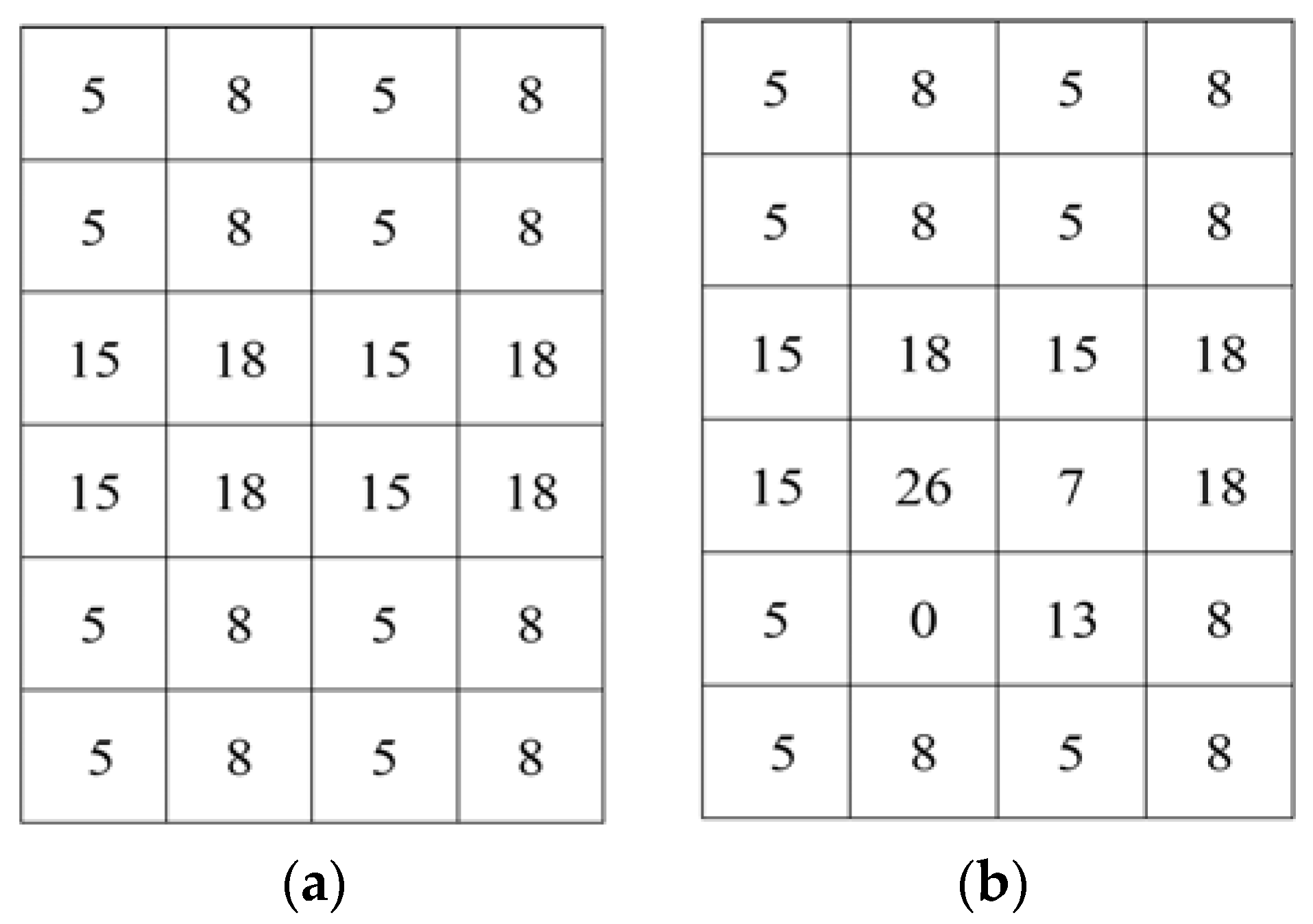
The estimated values in the prediction error in (3) and (4) are not good metrics, since the estimated value is different from the actual value. The smoothness calculation from using the prediction error leads to a worsened bit error rate. For this calculation, it is required to estimate the selected pixel by using four neighboring pixels of that pixel before calculating the prediction error. If the neighboring pixels are changed during the data embedding process, the pixel estimation will be failed and the prediction error calculation will be unsuccessful too. For example, let us consider the Figure 1a,b as the original image and embedded image, respectively. From Figure 1b, it is seen that some pixels and their neighboring pixels are changed due to embedding data. In this circumstance, the pixel from the neighboring pixels cannot be estimated accurately. For instance, let pixel 0 at position (5, 2) (Figure 1b) be the selected pixel. As their neighboring pixels {26, 13} are also changed, so it is not possible to estimate the value of that pixel from the neighboring pixels. So, the main constraint of prediction error is that the neighboring pixels cannot be changed which ultimately decreases the embedding rate. Therefore, in the proposed work, to reduce the bit error rate and increase the embedding rate, we use the absolute difference of neighboring pixels, instead of prediction error, for the smoothness calculation for both joint and separable methods.
In [21], Zhang introduced a separable RDH-EI method where the encrypted bits are compressed to accommodate the additional bits, S. Using a data-hiding key, the data-hider pseudo-randomly permutes and divides the encrypted image into groups with size of L. The M LSB-planes of each group are compressed with a matrix sized (M·L-S) × (M·L) and vacated room is used to embed data. As the additional bits are embedded in LSBs of the encrypted images, they can be extracted directly from the encrypted marked image by using a data-hiding key. On the receiver side, the marked encrypted image is decrypted and a total of 8-M most significant bits (MSB) of pixels are obtained. The receiver then estimates the M LSBs by the MSBs of neighboring pixels. By comparing the estimated bits with the vectors in the coset corresponding to the extracted vectors, the receiver can recover the original bits of the M LSBs. However, Zhang’s technique is little complicated and data cannot be extracted precisely and the original image cannot be recovered perfectly especially when the payload is high.
3. The Proposed Joint Data Hiding System
3.1. Procedures of Proposed Method
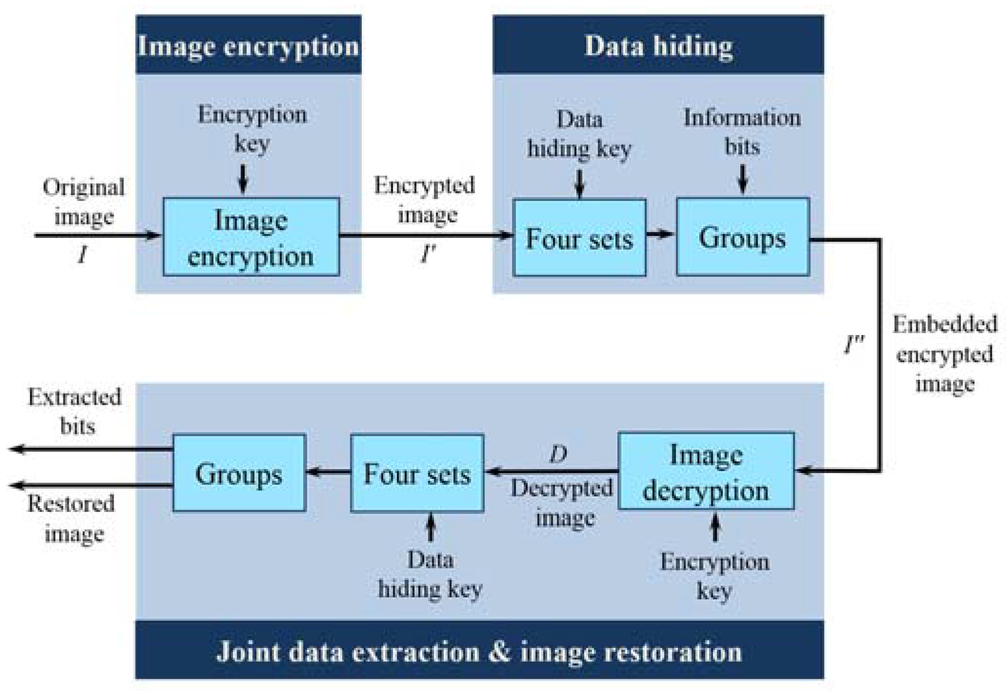
The proposed joint system has three phases: image encryption, data hiding, and joint data extraction and image restoration, as represented in Figure 2. In the image encryption phase, by using an encryption key, a content owner encrypts an original uncompressed image and creates an encrypted version of the original image. In the data hiding phase, by exploiting a data-hiding key, a data hider inserts some additional data within the encrypted image by modifying a small portion of the encrypted data. However, the data hider does not know any information about the original image. The encrypted image is divided into four sets, instead of blocks, and two sets can be used for data hiding, which helps to increase the embedding capacity. Besides, for security purposes, the information is further encrypted using data-hiding key. In the joint data extraction and image restoration phase, a receiver first decrypts the embedded encrypted image by using the encryption key to obtain a directly decrypted image that is similar to the original. Moreover, with the aid of a data-hiding key, the receiver can extract the embedded data and restore the original image from the directly decrypted image. In the proposed system, for fluctuation calculation, the actual value of pixels and the absolute difference between neighboring pixels are more preferred than an estimated value and prediction error, respectively. The detailed procedures are as follows.
3.1.1. Image Encryption
Since the content owner does not want the data hider to know any information about the original image, he encrypts the original image with an encryption key using a standard stream cipher. Among various papers for image encryption, we adopt the image encryption algorithm identical to Zhang’s [15] and others [16,17,18,19,20], in order to compare them conveniently and impartially.
It is assumed that I is a gray-level image of uncompressed format sized X × Y, in which every pixel with a gray value is represented by eight bits. Let Ii,j be a pixel at position (i,j), where Ii,j belongs to [0, 255] and 1 ≤ i ≤ X, 1 ≤ j ≤ Y. Ii,j,k denotes eight-bit binary digits of each pixel with a gray value, where k = [1, 8]. The relation between bits in a pixel and pixels with a gray value is denoted by
To encrypt the original image, random sequence Ri,j,k is generated according to the encryption key using a standard stream cipher. Then, bits of pixel Ii,j,k can be encrypted by a bitwise exclusive-or (XOR) of I and R:
From the bits of the encrypted pixel in (6), a pixel in the encrypted image can be written as follows:
3.1.2. Data Hiding
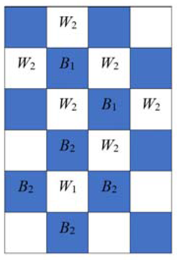
After the encryption phase, the encrypted image is sent to the data hider. Although the data hider does not know anything about the original image, the data hider can embed additional data into the encrypted image by changing a small portion of it. Before embedding, Q bits of information are permuted by using the data-hiding key; let A(1), A(2),…, A(Q) be the permuted information bits to be embedded. It is assumed that Q = QB + QW, where QB and QW are nonnegative integers for the number of embedded information bits in the two sets. In the data hiding phase, according to the data-hiding key, the pixels except the border pixels in the encrypted image, are divided into four sets, B1, B2, W1, and W2, where pixels in B1 and W1 can be used for embedding QB and QW information bits, respectively, and pixels in B2 and W2 can be used for data extraction. Border pixels can be the elements of B2 or W2 but cannot be the elements of B1 or W1, i.e., border pixels can be used for data extraction but cannot be used for data embedding. To embed one information bit, it is assumed that G pixels are considered. Therefore, the elements of B1 and W1 are QBG and QWG, respectively.
For convenience, it is assumed that B1 and B2 can be located at position (i,j), where (i + j) mod 2 = 0. Similarly, the elements of W1 and W2 can be located at position (i + j), where (i + j) mod 2 = 1 as shown in Figure 3. In the first round, according to the data-hiding key, pixel I’i,j is selected, and pixel I’i,j is assigned to B1 or W1, if (i + j) mod 2 is 0 or 1, respectively. Then, neighboring pixels I’i+1,j, I’i−1,j, I’i,j+1, and I’i,j-1 are assigned to W2 or B2, respectively. For the next round, we choose a new pixel I’i,j with i and j that are different from i and j in the previous round. If (i + j) mod 2 is 0, then the chosen pixel I’i,j becomes an element in B1, regardless of whether the chosen pixel I’i,j is an element of B2 or not, and neighboring pixels I’i+1,j, I’i−1,j, I’i,j+1, and I’i,j−1 are elements of W1 or W2 or not. However, the neighboring pixels that are not in W2 become elements in W2. The neighboring pixels in W1 or W2 are not changed. Similarly, if (i + j) mod 2 = 1, then the chosen pixel I’i,j is assigned to set W1, and the neighboring pixels not in set B2, become elements of B2. For example, as shown in Figure 3, we choose a pixel at position (2, 2) where i = 2 and j = 2. Since (2 + 2) mod 2 = 0, the first chosen pixel belongs to set B1 and neighboring pixels will be the elements in set W2. If the second selected pixel is located at the (3, 3) position, the chosen pixel belongs to set B1 since (3 + 3) mod 2 = 0. Since the top and left pixels are already in set W2, only the bottom and right pixels will be the elements in set W2. The third chosen pixel at position (5, 2) will belong to set W1 as (5 + 2) mod 2 = 1 and adjacent pixels will be the elements in B2. The next pixel can be selected at position (4, 3) and will belong to set W1. Though this pixel was already an element of set W2, the pixel can belong to W1 and the neighboring pixels that are not in B2 become the elements of B2. The selection process terminates when the elements of B1 and W1 become QBG and QWG.
After that, let C be a union of the positions of pixels in B1 and W1, and the number in C is QG. The set C can be divided into Q groups: Q1, Q2,…, QQ, sequentially. Then, the d th group, Qd, can be written as {(i1,d, j1,d), (i2,d, j2,d), …, (iG,d, jG,d)}, where d = 1, 2,…, Q. The d th group can embed the d th permuted information bit A(d). If an information bit to be embedded is 1, that is A(d) = 1, one bit of G pixels where positions are in Qd will be flipped. It is assumed that the t th bit can be flipped, where t is 4, 5, or 6. Here, the t th bit is flipped instead of the three LSBs to make the pixels more fluctuated. If an information bit to be embedded is 0, that is A(d) = 0, the t th bit of G pixels where the positions are in Qd will remain the same. When all the bits, A(1), A(2),…, A(Q) are embedded, an embedded encrypted image, I”, will be constructed and sent to the receiver.
3.1.3. Joint Data Extraction and Image Restoration
In this phase, if receivers have both the encryption and data-hiding keys, then they can extract the embedded information bits and restore the original image. To do this, receivers first generate a random sequence, Ri,j,k according to the encryption key using a standard stream cipher. Then, a bitwise XOR of I” and R is performed using the following equations:
Thus, a directly decrypted image is obtained, which is similar to the original except the t th bits of some chosen pixels in the directly decrypted image differ from those in the original image.
To extract information, receivers have to make the permutation, four sets, and G, which are same with ones in the sender by using the data-hiding key. To measure the fluctuation of d th group Qd and its flipped group , the following functions are defined:
where Di,j(x,d) represents the chosen pixels in the d th group, Qd and is the flipped pixels, which are achieved by flipping the t th bit of Di,j(x,d) and f0(d) and f1(d) are fluctuation functions of Qd and , respectively. For the fluctuation calculation, we use the actual value of the pixels, instead of the estimated value. Besides, we have considered the absolute difference between neighboring pixels rather than the prediction error, as used in (3) and (4), to reduce the bit error rate.
Fluctuation of the original group is generally lower than that of the flipped one due to the spatial correlation in natural images. Hence, by comparing f0(d) and f1(d), data extraction and image restoration can be performed. If f0(d) < f1(d), then Qd will be the original group, and 0 will be the extracted hidden bit, that is E(d) = 0. Otherwise, will be the original group, and 1 will be the extracted hidden bit, that is E(d) = 1. Eventually, extracted hidden bits E(1), E(2),…, E(Q) are concatenated to get the permuted information bits. Then, using the data-hiding key, hidden bits E(1), E(2),…, E(Q) are inversely permuted, and the original information bits are extracted. The restored groups are collected to make the original image. As the information bits are further permuted using the data-hiding key, it is impossible for attackers to get the original message without the data-hiding key.
3.2. Feasibilty of the Proposed Data Hiding System
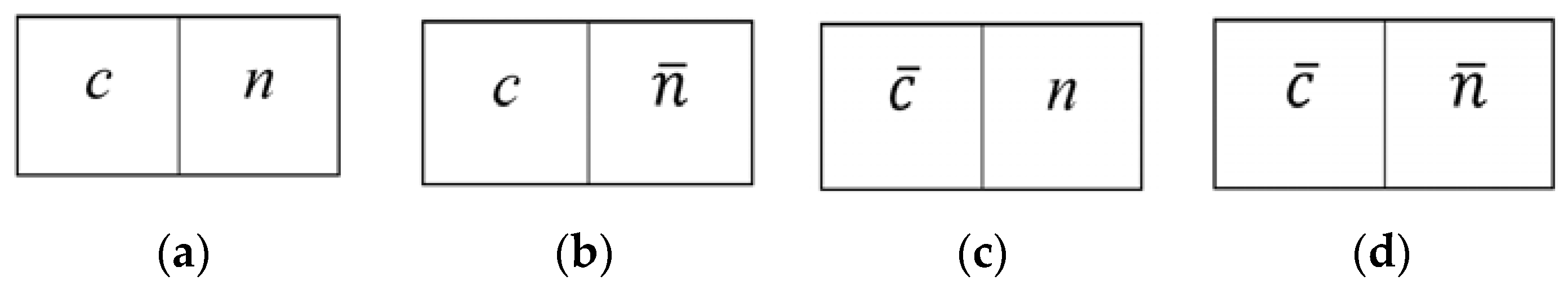
In the proposed scheme, information bits can be embedded in both B1 and W1. Since the fluctuation calculation is based on the smoothness of natural images, the difference of the chosen pixel and its neighboring pixels is usually used to measure the fluctuation. For example, let us consider two adjacent pixels, i.e., the chosen pixel and one of its neighboring pixels. Assume that the flip operation is performed randomly on all the pixels of the encrypted image. There are a total of four cases of two adjacent pixels, as shown in Figure 4 where c and represent the original and the flipped chosen pixels, n and represent the original and the flipped neighboring pixels, respectively.
On the basis of statistics, as shown in Figure 4a,b, the absolute difference value of c and its neighboring pixel is ; the absolute difference value of and its neighboring pixel is as depicted in Figure 4c,d. The net difference of the above two values is
According to (12), Figure 4b,c are basically same, since the absolute difference values of the two adjacent pixels of Figure 4b,c are statistically the same, i.e., |c − n|−| − n| = 0. Moreover, from (13) as stated in [15], because of spatial correlation in the natural image, the absolute difference value of the original pixel is generally lower than that of a seriously interfered version, i.e., the flipped pixels. Thus, c and could be distinguished, regardless of whether its neighboring pixel is flipped or not. In other words, both sets could be used for data embedding; the embedding capacity is indeed enlarged.
3.3. An Example of the Proposed Joint Data Hiding System
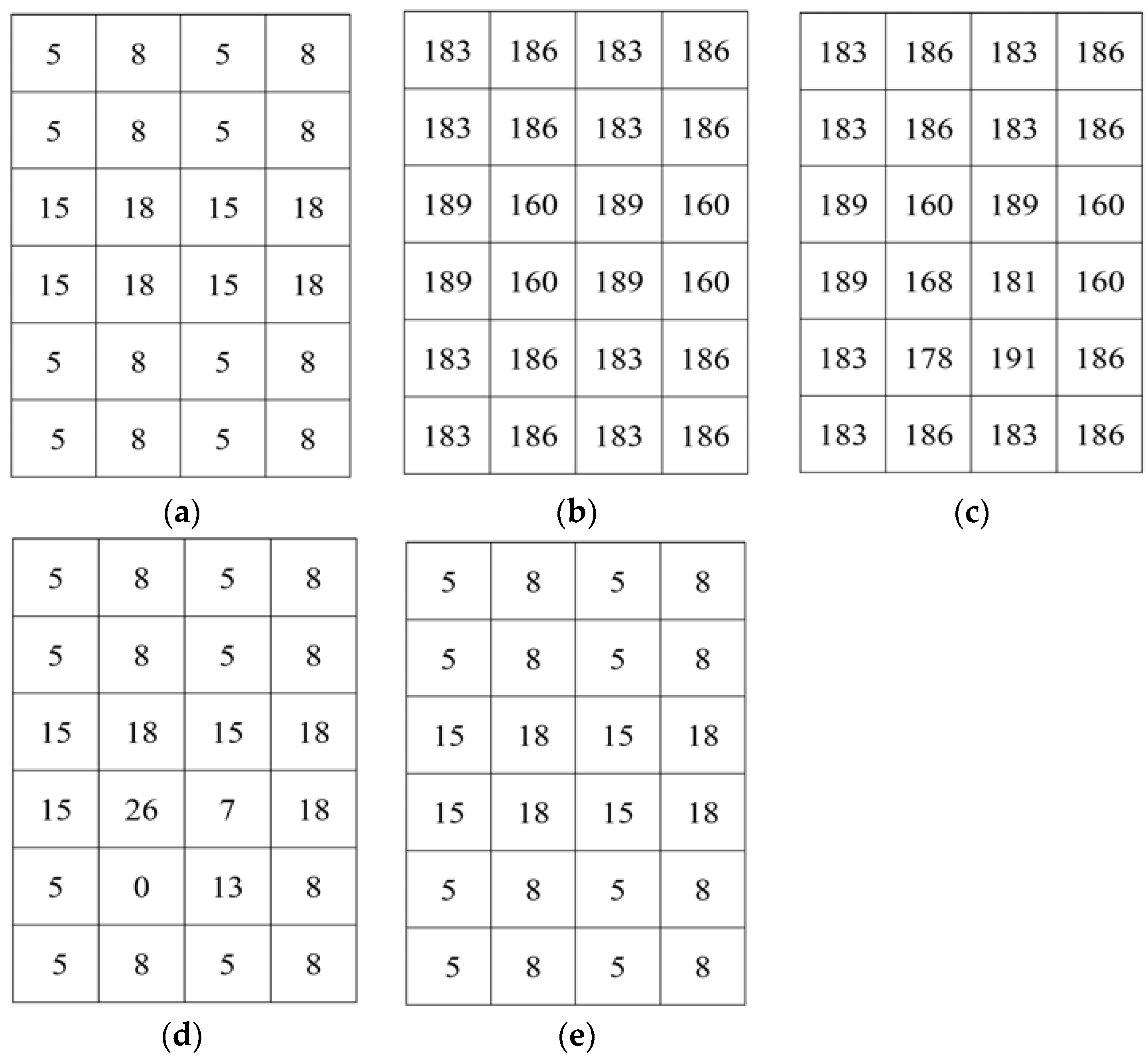
To illustrate our proposed joint data hiding system, a simple example is considered. Let I be the original image of size 4 × 6, as shown in Figure 5a. First, I is encrypted by using the encryption key and encrypted image I’ is obtained, as demonstrated in Figure 5b. Then, the information bits are embedded into I’. It is assumed that t = 4. We consider Q = 4, the four bits to be embedded are 1001 and after permutation the permuted bits, A = 0101. Here, QB = 2 and QW = 2. Let G = 2, i.e., two pixels are required to embed one bit. I’ is divided into four sets B1, B2, W1, and W2. Border pixels can be the elements of B2 or W2 but cannot be the elements of B1 or W1. Let the first chosen pixel be 186 at position (2, 2) where i = 2 and j = 2. Since (2 + 2) mod 2 = 0, this pixel will belong to set B1 and neighboring pixels {186,183,160,183} will be the elements in set W2. The second pixel, 189 at (3, 3), will belong to set B1 as (3 + 3) mod 2 = 0, and as top and left pixels {183,160} are already in set W2, only bottom and right pixels {189,160} will be the elements in set W2. The third pixel, 183 at position (3, 2), will belong to set W1 as (3 + 2) mod 2 = 1, and neighboring pixels {183,186,189,186} will be elements in B2. The process is continued until number of pixels in B1 and W1 exceeds 4. Let B1 and W1 be B1 = {186,189,160,183} and W1 = {183,160,189,186},respectively.Therefore, C is determined as C = {186,189,160,183,183,160,189,186}. These pixels are divided into four groups and each group contains two pixels. If it is assumed that the first group is {186,189} and first bit to be embedded is 0, the pixels in this group will be the same. If the second group is {160,183} and bit to be embedded is 1, then t th bit of all pixels in this group is flipped. Thus, after embedding all the bits, embedded encrypted image is shown in Figure 5c.
For joint data extraction and image restoration, the embedded encrypted image has to be decrypted using the same encryption key. In this example, the decrypted embedded image is given in Figure 5d. The decrypted image is divided into four sets which are the same with the sets in the data embedding process and the selected pixels are {8,15,26,13,5,18,7,0}. Then, the pixels are divided into groups and for each group another flipped group is obtained by flipping the t th bit. For example, {0,7} is the flipped group of {8,15} where the fourth bit of each pixel in group {8,15} is flipped. Fluctuation of {8,15} and {0,7} are calculated by using (10) and (11), respectively. Let f0 = 40 and f1 = 60. As f0 < f1, {8,15} is the original group and the extracted bit is 0. The last group is {7,0} and its flipped group is {15,8}. Let f0 = 96 and f1 = 42. As f1 < f0, {15,8} is the original group and the extracted bit is 1. After extracting all information bits, a recovered image is shown in Figure 5e.
4. The Proposed Separable Data Hiding System
In the joint data hiding system, data extraction and image restoration are inseparable as they are extremely related. If someone has the data-hiding key but not the encryption key, he cannot extract the embedded information bits from the embedded encrypted image.
In this section, we present a separable reversible data hiding system in encrypted images, where data extraction and image restoration are separable. There are four phases: image encryption, data hiding, data extraction, and image restoration is demonstrated in Figure 6. In the proposed scheme, the original image is encrypted using an encryption key and the additional data are embedded into the encrypted image with the aid of a data-hiding key. With an encrypted image containing additional data, if the receiver has only the data-hiding key, he can extract the additional data though he does not know the image content. When, he has only the encryption key, he can decrypt the received data and obtain a filtered decrypted image similar to the original one, but cannot extract the embedded additional data. If the receiver has both the data-hiding key and the encryption key, he can extract the additional data and restore the original image without any error. In the proposed system, to calculate the fluctuation, we have exploited the real value of pixels and the absolute difference between adjacent pixels in place of an estimated value and prediction error, respectively. Herein, data extraction must be carried out before image decryption.
4.1. Image Encryption
In the image encryption phase, by using an encryption key, a content owner encrypts the original uncompressed image to obtain an encrypted image. The encryption procedure is the same as that in the joint system.
4.2. Data Hiding
In data hiding phase, a data hider embeds additional information bits into the encrypted image, I’. The detailed embedding steps are as follows.
Step 1: Before embedding, Q bits of information are permuted by using the data-hiding key; let A(1), A(2),…, A(Q) be the permuted information bits to be embedded.
Step 2: Then, according to the data-hiding key, the data hider pseudo-randomly selects Q pixels from the encrypted image. The selection process is the same as that in the data hiding phase of the joint system. Let I’(1), I’(2),…, I’(Q), be the Q selected pixels in the encrypted image.
Step 3: The t th bits of the I’(1), I’(2),…, I’(Q), pixels are collected, where t ≥ 7. Then, the information bits are embedded by replacing the t th bits of the corresponding selected pixels with A(1), A(2),…, A(Q). Herein, the information bits are concealed in the most significant bits or the second most significant bits. Then, the embedded encrypted image I” is sent to the receiver.
4.3. Data Extraction
In this phase, we consider that the receiver only has the data-hiding key. With the aid of data-hiding key, the receiver extracts the embedded information bits by adopting following steps.
Step 1: The receiver pseudo-randomly selects Q pixels from the embedded encrypted image according to the data-hiding key as did in the data hiding phase. Let I”(1), I”(2),…, I”(Q), be the Q selected pixels in the embedded encrypted image.
Step 2: The t th bits of I”(1), I”(2),…, I”(Q) pixels are collected and these bits are the permuted extracted information bits. Let E(1), E(2),…, E(Q) be the extracted bits. The t th bits can be extracted by using following equation
Step 3: By exploiting the data-hiding key, the permuted extracted bits E(1), E(2),…, E(Q) are inverse permuted to get the actual information bits.
Note that, because of the pseudo-random pixel selection and permutation of information bits, any attacker without the data-hiding key cannot obtain the pixel locations, and therefore cannot extract the embedded data. Furthermore, although the receiver having the data-hiding key can successfully extract the embedded data, he cannot get any information about the original image content.
4.4. Image Restoration
In the image restoration phase, we consider two cases: (1) the receiver only has the encryption key; and (2) the receiver has both the data hiding and encryption keys.
When the receiver has the encryption key but does not know the data-hiding key, undoubtedly, he cannot extract the embedded data without data-hiding key. However, the original image content can be roughly restored. To do this, receivers first generate a random sequence, Ri,j,k according to the encryption key using a standard stream cipher. Then, a bitwise XOR of I” and R is performed to decrypt the encrypted image. Since some most significant bits or second-most significant bits are modified in the separable method, it introduces salt-and-pepper noise on the directly decrypted image. Then, a median filtering is applied to the directly decrypted image to suppress the noise, and a filtered decrypted image is obtained.
When the receiver has both the data hiding and encryption keys, he can extract the embedded bits and resort the encrypted image to the original version. The detailed steps are as follows.
Step 1: With the aid of data-hiding key, pixels with hidden bits are selected and by fetching the t th bit of the corresponding chosen pixel, embedded bits are extracted. By using the data-hiding key, the extracted bits are inverse permuted to get the actual information bits.
Step 2: A random sequence, Ri,j,k is obtained according to the encryption key using a standard stream cipher. These bits are utilized to decrypt the encrypted image and directly decrypted image, D is obtained. In the directly decrypted image, only the t th bits of the Q specific pixels may differ from the original.
Step 3: From the directly decrypted image, the receiver pseudo-randomly chooses Q pixels by using the data-hiding key. Let D(1), D(2),…, D(Q), be the Q selected pixels in the directly decrypted image.
Step 4: By setting the t th bit as 0 and 1, two possible values of D(d) are achieved. Let D0(d) and D1(d) be the two possible values of D(d), respectively.
Step 5: The fluctuation function of D0(d) and D1(d) are calculated as follows
By comparing f0(d) and f1(d), image restoration can be performed. If f0(d) < f1(d), then D0(d) will be the original pixel. Otherwise, D1(d) will be the original pixel. When Q original pixels are obtained, the original image is restored.
4.5. An Example of the Proposed Separable Data Hiding System
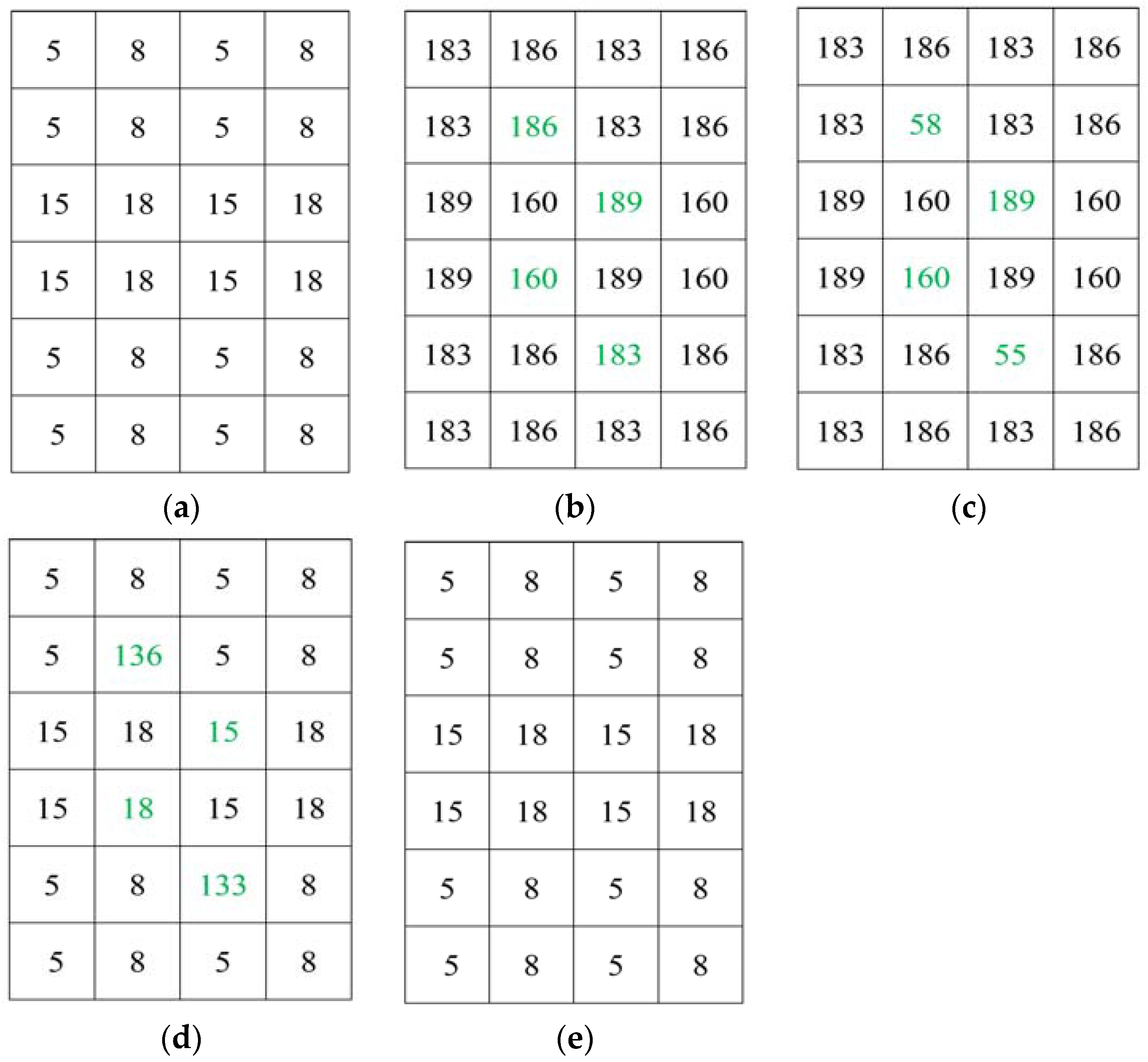
To illustrate our proposed separable data hiding system, a simple example is included. Let I be the original image of size 4 × 6, as shown in Figure 7a. First, by using the encryption key, I is encrypted and encrypted image I’ is obtained, as demonstrated in Figure 7b. Then, the information bits can be embedded into I’ and it is considered that the four bits to be embedded are 1001, and after permutation the permuted bits are A = 0110. Let Q selected pixels be {186,189,160,183} that are marked with green in Figure 7b. The most significant bits of the pixels are collected and replaced with A = 0110. Thus, the embedded encrypted image is obtained, as shown in Figure 7c. In the separable method, we can extract the data from the embedded encrypted image. To extract the hidden bits, we need to collect Q pixels {58,189,160,55} and fetch the t = 8 th bit by using (14). Then, the extracted bits are permuted to get the original information. For image restoration, first the embedded encrypted image is decrypted. The directly decrypted image (Figure 7d) is similar to original except some pixels. Then, we collect the pixels {136,15,18,133} from the directly decrypted image. By setting the t th bit as 0 and 1, two possible values of each pixel are achieved. Let us consider two possible cases of the pixel 136, which are t = 0, D0 = 8 and t = 1, D1 = 136. The fluctuation of D0 and D1 is calculated from (15) and (16), respectively. After calculation, we get f0 = 16 and f1 = 508. As f0 < f1, then D0 = 8 will be the original pixel. Therefore, we will restore the original pixels and collect them to restore the original image, as demonstrate in Figure 7e.
5. Experimental Results and Discussion
In our simulation, we consider four gray-level images (Lena, Jet, Peppers, and Sailboat) sized 512 × 512 as test images, as shown in Figure 8 [24], for both joint and separable systems.
5.1. Joint System
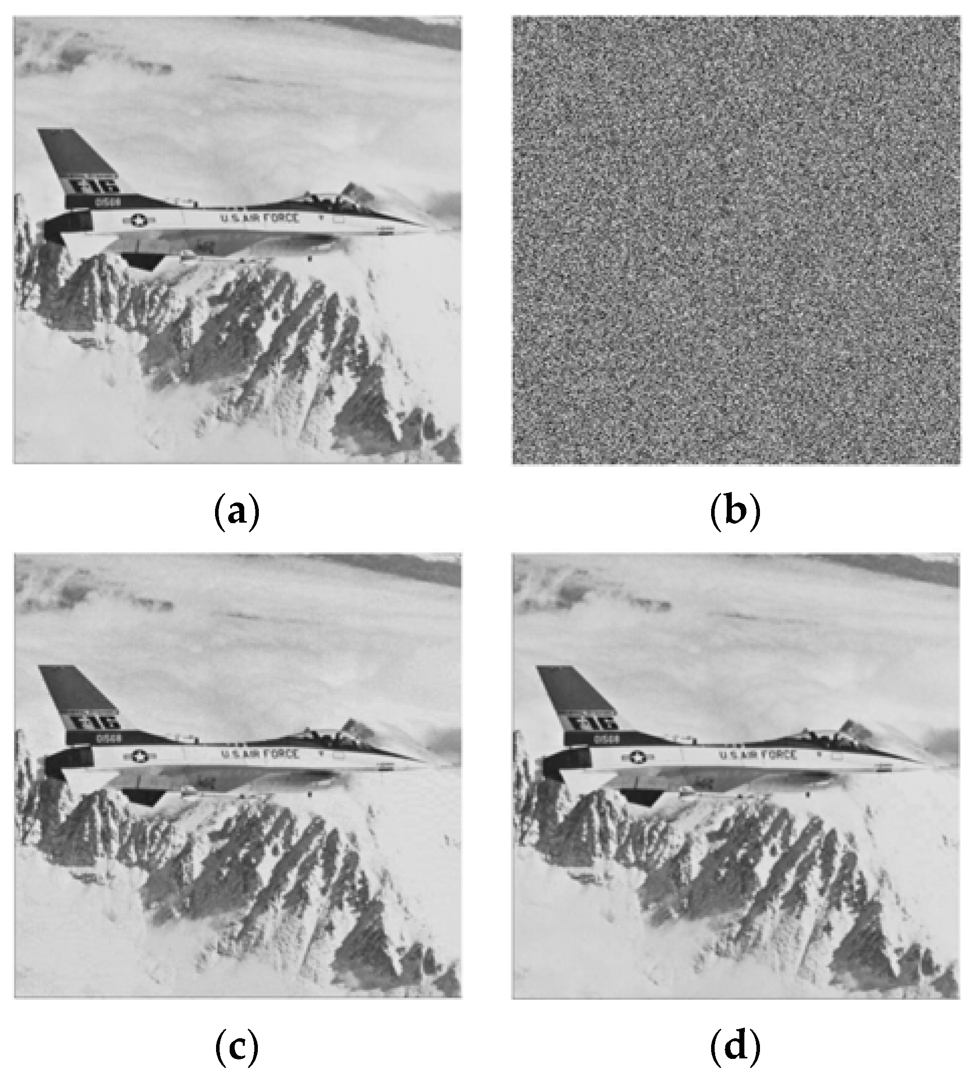
For joint data hiding system, as shown in Figure 9a, original test image Lena is encrypted to generate Figure 9b. Then, we embed 7225 bits (equivalent to a block size of 6 × 6 [15,16,17]) into the encrypted image by setting t = 5 and G = 15. After that, the image was decrypted as seen in Figure 9c. Finally, the hidden bits were successfully extracted and the original image was perfectly restored from the directly decrypted image as shown in Figure 9d.
Table 1, Table 2, Table 3 and Table 4 show the performance analysis of the proposed system for test images Lena, Jet, Peppers, and Sailboat, respectively. For the performance analysis, we consider bit error rate (BER) and embedding rate. The BER is the ratio of unrecovered bits to the total number of embedded bits, and the embedding rate is the ratio of the total embedded bits to the total pixels in the image. Figure 10 is a graphical representation of the bit error rate (%) versus data-embedding capacity (bits) for all the images. From the tables and Figure 10, we can see that the error rate increases with an increase in the embedding rate. If we embed more bits, then the error rate will also be higher. For the Lena image (Table 1 and Figure 10), when 16,384 bits (equivalent to a block size of 4 × 4 [15,16,17]) are embedded, that is the embedding rate is 0.0625, the error rate is 0; however, with 28,900 bits (equivalent to a block size of 3 × 3 [15,16,17]), the embedding rate is 0.11, and the error rate increases to 0.01. With the Jet image, as shown in Table 2 and Figure 10, when the embedding rate increases from 0.0275 to 0.0625, the error rate also rises from 0 to 0.04. Table 3 and Table 4 also show similar results.
Figure 10 also shows that the BER performance with the Lena image is better than the other images, since the spatial correlation of the Lena image is stronger than the other images. For Lena, 16,384 bits can be embedded error-free, whereas in the Jet and Pepper images, 7225 bits can be embedded error-free. On the other hand, the BER performance with Sailboat is worse than the other images because of weak spatial correlation. Therefore, the BER in the data hiding system depends on spatial correlation, too.
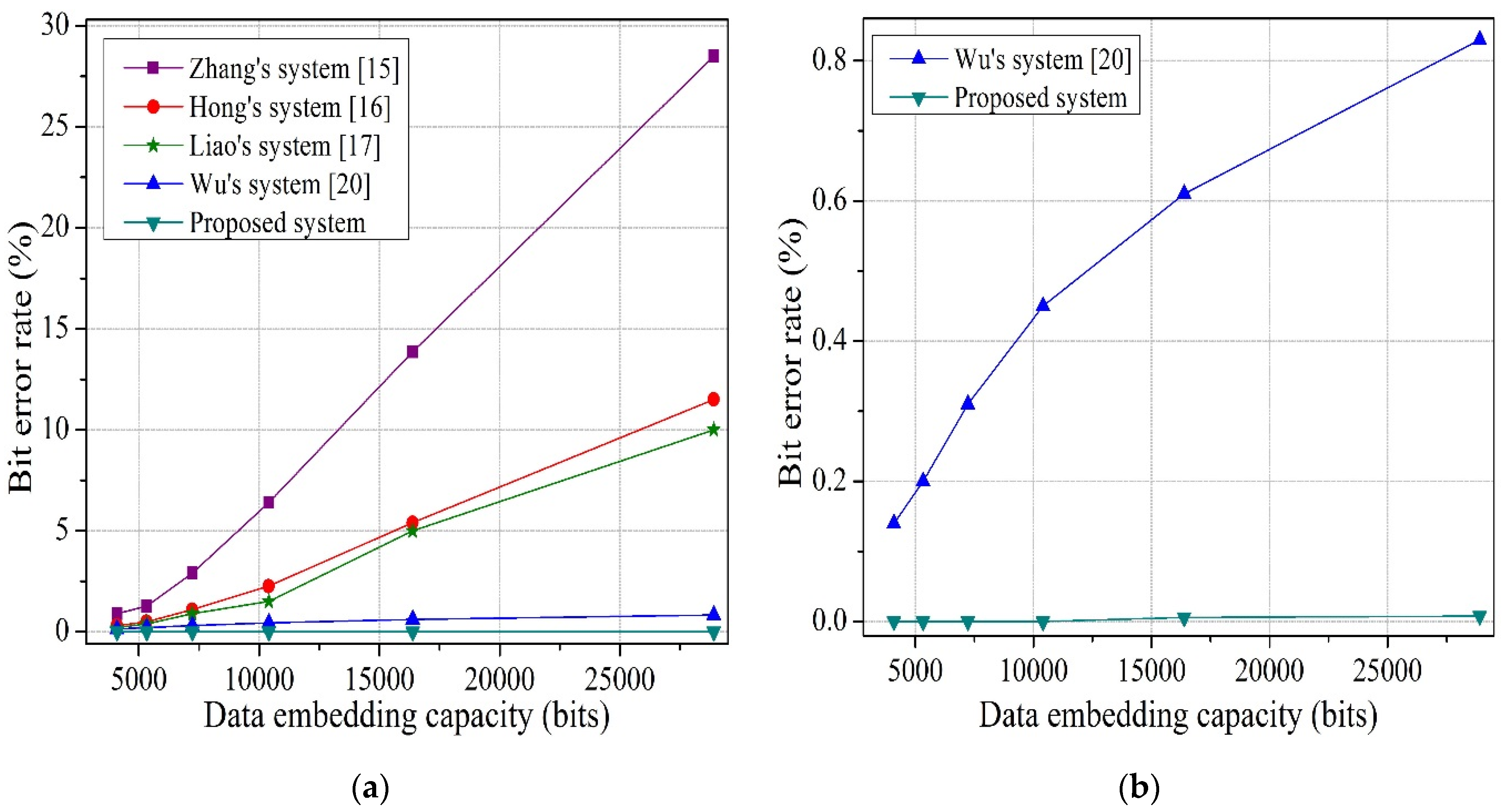
Figure 11, Figure 12, Figure 13 and Figure 14 show bit error rate comparisons between the proposed system and the referenced systems (based on embedded bits) for test images, Lena, Jet, Peppers, and Sailboat, respectively. In Figure 11a, Figure 12a, Figure 13a, and Figure 14a, the difference between the proposed system and Wu and Sun [20] is small due to the scaling factor. So, we draw Figure 11b, Figure 12b, Figure 13b, and Figure 14b, to compare the proposed system and Wu and Sun [20] and to indicate the difference clearly. For Lena, as shown in Figure 11, when 16,384 bits are embedded, the error rates for the Zhang [15], Hong et al. [16], and Liao et al. [17] systems are 15.8, 7.9, and 6.62%, respectively; whereas, the BER of the proposed system is 0, which is significantly lower than other systems. At 28,900 bits, the error rate for the Wu and Sun system [20] is 0.04%, and the result of the proposed system is 0.01%, which is four times smaller than Wu and Sun’s. As seen in Figure 12, for the Jet image, the BER for Zhang [15], Hong et al. [16], Liao et al. [17], and Wu and Sun [20] systems are 18.6, 8.1, 7.2, and 0.24%, respectively; however, with the proposed system, the error rate is only 0.04%, which is significantly lower than the others. For the Peppers and Sailboat images, (Figure 13 and Figure 14) the proposed system provides better performance than other systems. BER of the proposed scheme is almost equal to 0, since we divide the encrypted image into sets, instead of blocks; which helps to exploit the spatial correlation in natural images perfectly. Moreover, the actual value of pixels is considered, rather than an estimated value, and the absolute difference between neighboring pixels is used in preference to prediction error to calculate the smoothness.
5.2. Separable System
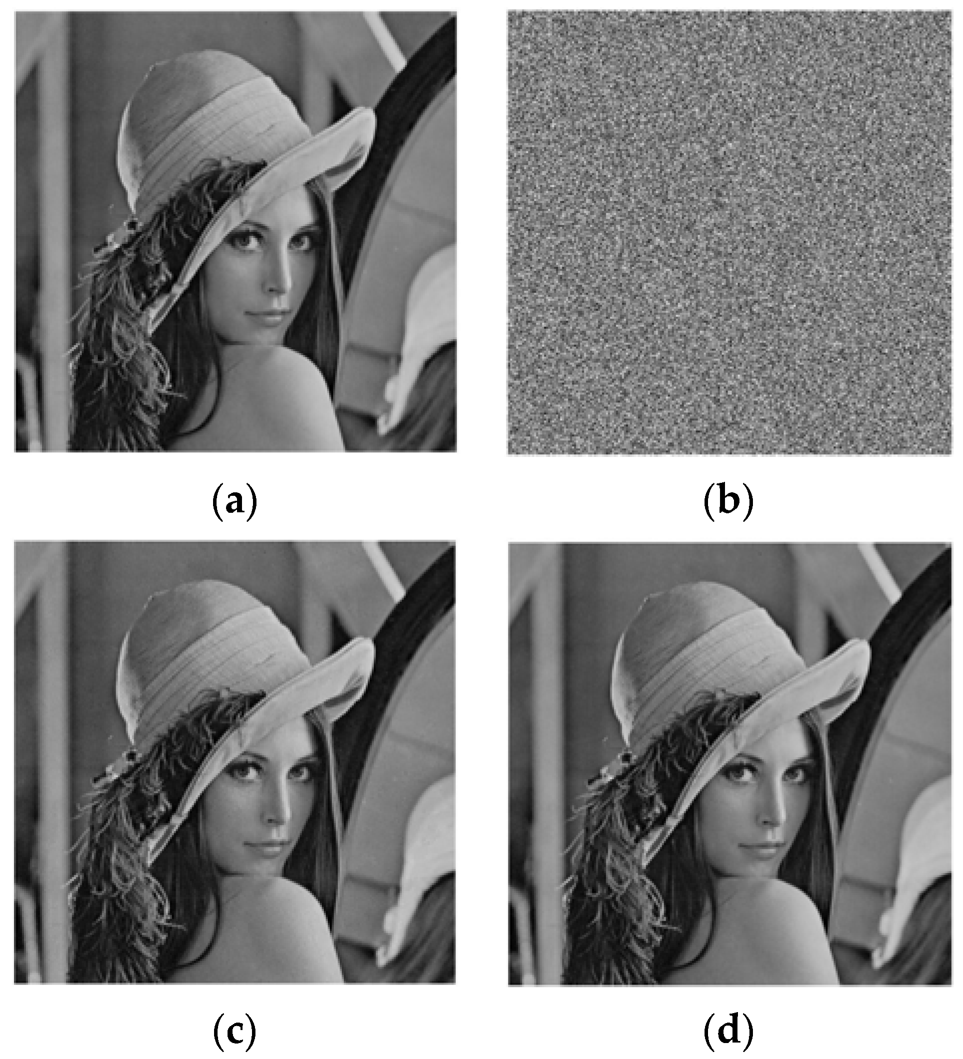
The test image Jet sized 512 × 512 shown in Figure 15a is used as the original image in the experiment of separable system. After image encryption, we embed 16,384 bits into the encrypted image by setting t = 8. That means we have embedded the information bits into the most significant bits of selected pixels. With an encrypted image containing information bits (Figure 15b), we can extract the information bits without any error using the data-hiding key. If we directly decrypt the encrypted image containing information bits with the encryption key and filter the directly decrypted image using a median filter, then, we get a filtered decrypted image, as given in Figure 15c. By exploiting both the data-hiding and the encryption keys, the embedded data can be successfully extracted and the original image can be perfectly restored from the encrypted image containing information bits. The restored image is demonstrated in Figure 15d.
To evaluate the performance of the separable system, extensive experiments are conducted, as illustrated in Table 5. In the separable method, all the embedded bits are extracted without any error. As a result, bit error rate of the extracted data is 0, and it is not mentioned in the table. In Table 5, we compare the peak signal-to-noise ratio (PSNR(dB)) of the recovered image between the proposed system and the referenced systems (based on embedding rate) for test images, Lena, Jet, Peppers, and Sailboat. For test image Lena (Table 5), the original image can be losslessly recovered for all the embedding rates by the proposed system and Wu and Suns’ system [20]. However, PSNR in Zhang’s system [21] is 44.65 dB when embedding rate is 0.1563 bpp which is significantly lower than the proposed system. For Jet and Peppers images (Table 5), complete reversibility is provided by the proposed system. However, these test images cannot be recovered to the original ones by Zhang’s [21] and Wu and Suns’ methods [20] for the demonstrated embedding rates. For the Sailboat image (Table 5), PSNR of the proposed system is 57.16 dB when 40,960 bits are embedded which is higher than other systems. That means, except the Sailboat image, the proposed separable system obtains complete reversibility especially when high embedding rates are used. As our proposed image restoration is based on spatial correlation of natural images, the Sailboat image due to the weak spatial correlation shows worse performance than other test images, especially when the embedding rate is high. It can be seen that the smoother the test image, the better the performance of image recovery is. When the embedding rate is 0.0625 for most test images, the original image can be successfully recovered. One of the techniques to guarantee small error probability over any circumstances, especially for weak correlated images, is to use data hiding systems with smaller embedding rates. However, there is a trade-off relation between embedding rates and performances.
6. Conclusions
In this work, two (joint and separable) reversible data hiding systems using an enhanced embedding pattern and a new measurement function in encrypted images which offer a high payload are proposed. In the joint system, data extraction and image restoration are done jointly. Here, the encrypted image is divided into four sets, instead of blocks, and two sets can be used for data hiding, which helps to increase the embedding capacity. Moreover, we consider the actual value of pixels, instead of an estimated value, and we exploit the absolute difference between neighboring pixels in preference to prediction error to calculate the smoothness. By avoiding block division and prediction error, we use the spatial correlation property of the natural images fully. For this reason, performance of the proposed work is superior to the performance of other works. In the separable method, data extraction and image recovery are separable and the hidden information bits are extracted without any error. Besides, as we avoid prediction error for separable method too, the proposed separable scheme outperforms other works in terms of reversibility. Furthermore, before hiding data, we can encrypt the information bits to further increase the security of the system.
Acknowledgments
This research was supported by Basic Science Research Program through the National Research Foundation of Korea (NRF-2014R1A1A1004521, NRF-2016R1D1A1B03934653).
Author Contributions
All authors discussed the contents of the manuscript and contributed to its presentation. Fatema-Tuz-Zohra Khanam designed and implemented the proposed scheme, analyzed the simulation data, and wrote the paper under the supervision of Sunghwan Kim.
Conflicts of Interest
The authors declare no conflict of interest.
References
- Hong, W.; Chen, T. A novel data embedding method using adaptive pixel pair matching. IEEE Trans. Inf. Forensics Secur. 2012, 7, 176–184. [Google Scholar] [CrossRef]
- Hussain, M.; Wahab, A.W.A.; Javed, N.; Jung, K.H. Hybrid data Hiding Scheme Using Right-Most Digit Replacement and Adaptive Least Significant Bit for Digital Images. Symmetry 2016, 8, 1–21. [Google Scholar] [CrossRef]
- Hong, W.; Chen, T.S.; Yin, Z.; Luo, B.; Ma, Y. Data hiding in AMBTC images using quantization level modification and perturbation technique. J. Vis. Commun. Image Represent. 2017, 76, 3761–3782. [Google Scholar] [CrossRef]
- Tian, J. Reversible data embedding using a difference expansion. IEEE Trans. Circuits Syst. Video Technol. 2003, 13, 890–896. [Google Scholar] [CrossRef]
- Ni, Z.; Shi, Y.Q.; Ansari, N.; Su, W. Reversible data hiding. IEEE Trans. Circuits Syst. Video Technol. 2006, 16, 354–362. [Google Scholar]
- Thodi, D.M.; Rodriguez, J.J. Expansion embedding techniques for reversible watermarking. IEEE Trans. Image Process. 2007, 16, 721–730. [Google Scholar] [CrossRef] [PubMed]
- Luo, L.; Chen, Z.; Chen, M.; Zeng, X.; Xiong, H. Reversible image watermarking using interpolation technique. IEEE Trans. Circuits Syst. Video Technol. 2010, 5, 187–193. [Google Scholar]
- Hong, W.; Chen, T.S. Reversible data embedding for high quality images using interpolation and reference pixel distribution mechanism. J. Vis. Commun. Image Represent. 2011, 22, 131–140. [Google Scholar] [CrossRef]
- Hong, W.; Chen, T.S.; Chen, J. Reversible data hiding using delaunay triangulation and selective embedment. Inf. Sci. 2015, 308, 140–154. [Google Scholar] [CrossRef]
- Kumar, M.; Agarwal, S. Reversible data hiding based on prediction error and expansion using adjacent pixels. Secur. Commun. Netw. 2016, 9, 3703–3712. [Google Scholar] [CrossRef]
- Lian, S.; Liu, Z.; Ren, Z.; Wang, H. Commutative encryption and watermarking in video compression. IEEE Trans. Circuits Syst. Video Technol. 2007, 17, 774–778. [Google Scholar] [CrossRef]
- Cancellaro, M.; Battisti, F.; Carli, M.; Boato, G.; Natale, F.G.B.; Neri, A. A commutative digital image watermarking and encryption method in the tree structured haar transform domain. Signal Process. Image Commun. 2011, 26, 1–12. [Google Scholar] [CrossRef]
- Ma, K.; Zhang, W.; Zhao, X.; Yu, N.; Li, F. Reversible data Hiding in encrypted images reserving room before encryption. IEEE Trans. Inf. Forensics Secur. 2013, 8, 553–562. [Google Scholar] [CrossRef]
- Cao, X.; Du, L.; Wei, X.; Meng, D.; Guo, X. High capacity reversible data hiding in encrypted images by patch-level sparse representation. IEEE Trans. Cybern. 2016, 46, 1132–1143. [Google Scholar] [CrossRef] [PubMed]
- Zhang, X. Reversible data hiding in encrypted images. IEEE Signal Process. Lett. 2011, 18, 255–258. [Google Scholar] [CrossRef]
- Hong, W.; Chen, T.; Wu, H. An improved reversible data hiding in encrypted images using side match. IEEE Signal Process. Lett. 2012, 19, 199–202. [Google Scholar] [CrossRef]
- Liao, X.; Shu, C. Reversible data hiding in encrypted images based on absolute mean difference of multiple neighboring pixels. Vis. Commun. Image Represent. 2015, 28, 21–27. [Google Scholar] [CrossRef]
- Pan, Z.; Wang, L.; Hu, S.; Ma, X. Reversible data hiding in encrypted image using new embedding pattern and multiple judgements. Multimed. Tools Appl. 2016, 75, 8595–8607. [Google Scholar] [CrossRef]
- Li, M.; Xiao, D.; Peng, Z.; Nan, H. A modified reversible data hiding in encrypted images using random diffusion and accurate prediction. ETRI J. 2014, 36, 325–328. [Google Scholar] [CrossRef]
- Wu, X.; Sun, W. High-capacity reversible data hiding in encrypted images by prediction error. Signal Process. 2014, 104, 387–400. [Google Scholar] [CrossRef]
- Zhang, X. Separable reversible data hiding in encrypted image. IEEE Trans. Inf. Forensics Secur. 2012, 7, 826–832. [Google Scholar] [CrossRef]
- Qian, Z.; Zhang, X. Reversible data hiding in encrypted images with distributed source encoding. IEEE Trans. Circuits Syst. Video Technol. 2016, 26, 636–646. [Google Scholar] [CrossRef]
- Xiao, D.; Xiang, Y.; Zheng, H.; Wang, Y. Separable reversible data hiding in encrypted image based on pixel value ordering and additive homomorphism. J. Vis. Commun. Image Represent. 2017. [Google Scholar] [CrossRef]
- USC-SIPI Image Database. Available online: http//sipi.usc.edu/database/ (accessed on 2 March 2016).
Figure 1.
Example to evaluate the prediction error. (a) original image; (b) embedded image.

Figure 2.
Block diagram of the proposed joint data hiding system.

Figure 3.
Pixels allocation in sets.

Figure 4.
Four cases of two adjacent pixels.

Figure 5.
Example of the proposed joint data hiding system. (a) Original image; (b) encrypted image; (c) encrypted image containing information bits; (d) decrypted image containing information bits; and (e) recovered image.
Figure 5.
Example of the proposed joint data hiding system. (a) Original image; (b) encrypted image; (c) encrypted image containing information bits; (d) decrypted image containing information bits; and (e) recovered image.

Figure 6.
Block diagram of the proposed separable data hiding system.
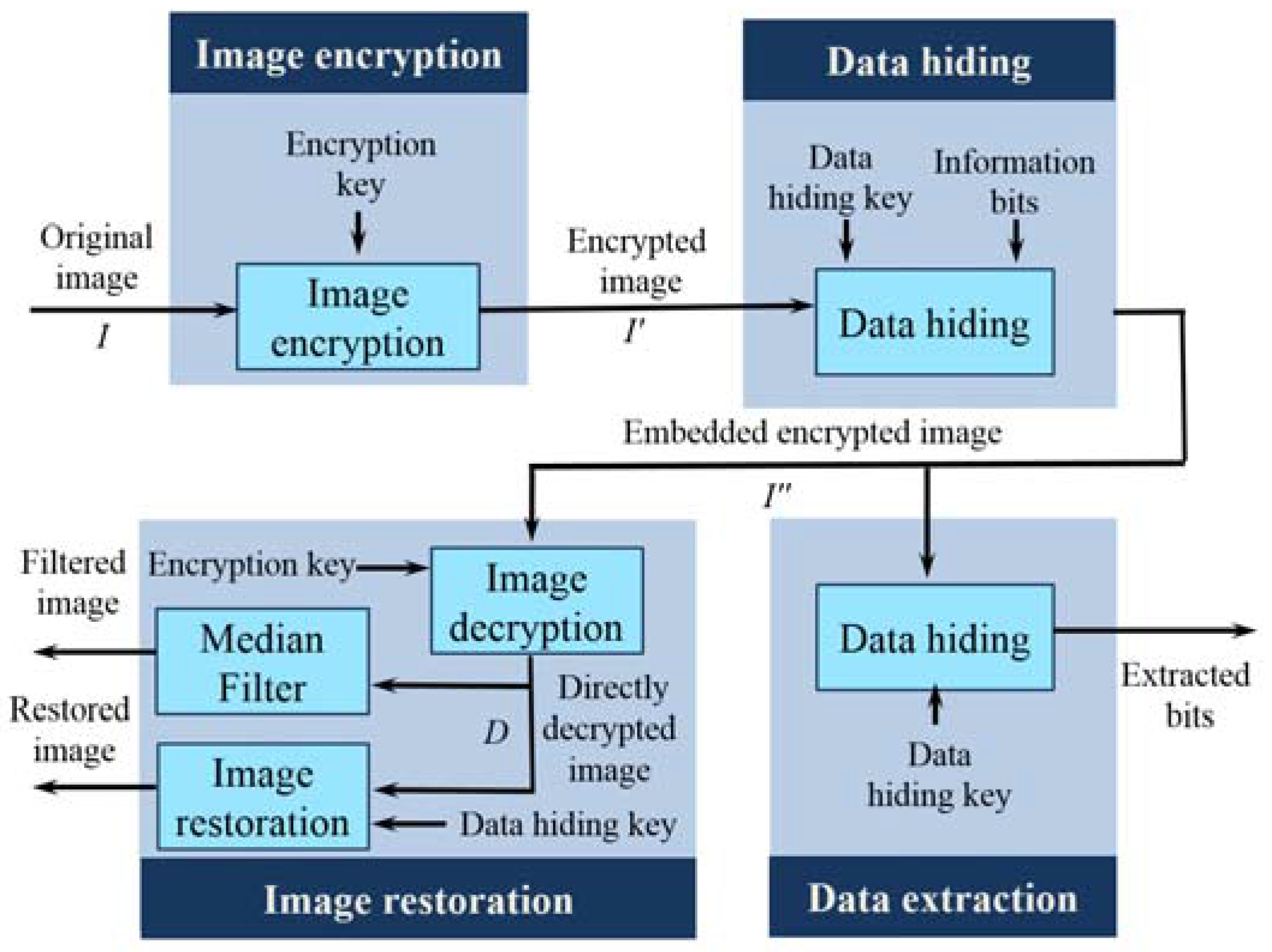
Figure 7.
Example of the proposed separable data hiding system. (a) Original image; (b) encrypted image; (c) encrypted image containing information bits; (d) decrypted image containing information bits; and (e) recovered image.
Figure 7.
Example of the proposed separable data hiding system. (a) Original image; (b) encrypted image; (c) encrypted image containing information bits; (d) decrypted image containing information bits; and (e) recovered image.

Figure 8.
Test images used for the simulation (a) Lena; (b) Jet; (c) Peppers; and (d) Sailboat [24].
Figure 8.
Test images used for the simulation (a) Lena; (b) Jet; (c) Peppers; and (d) Sailboat [24].
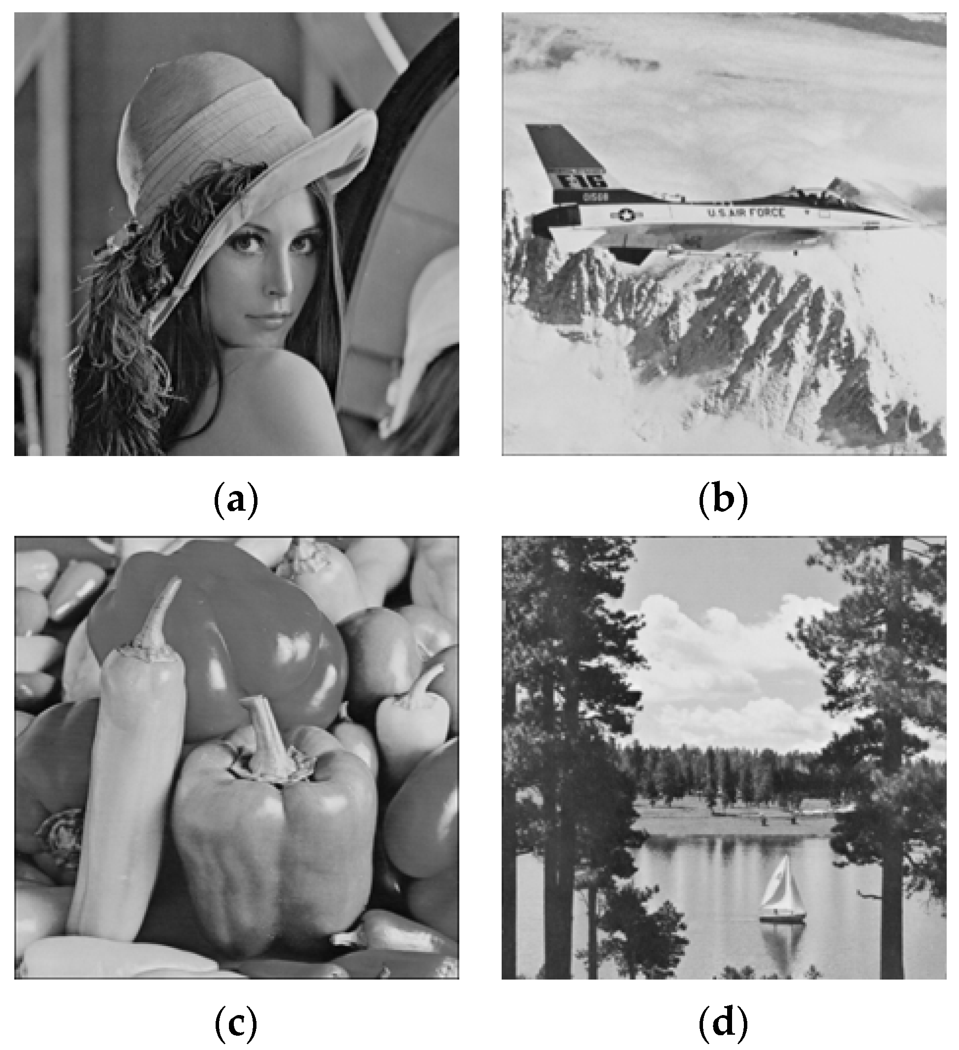
Figure 9.
Experiment by joint system. (a) Original Lena; (b) encrypted Lena; (c) decrypted Lena containing information bits; and (d) recovered Lena.
Figure 9.
Experiment by joint system. (a) Original Lena; (b) encrypted Lena; (c) decrypted Lena containing information bits; and (d) recovered Lena.

Figure 10.
Bit error rate vs. data embedding capacity.
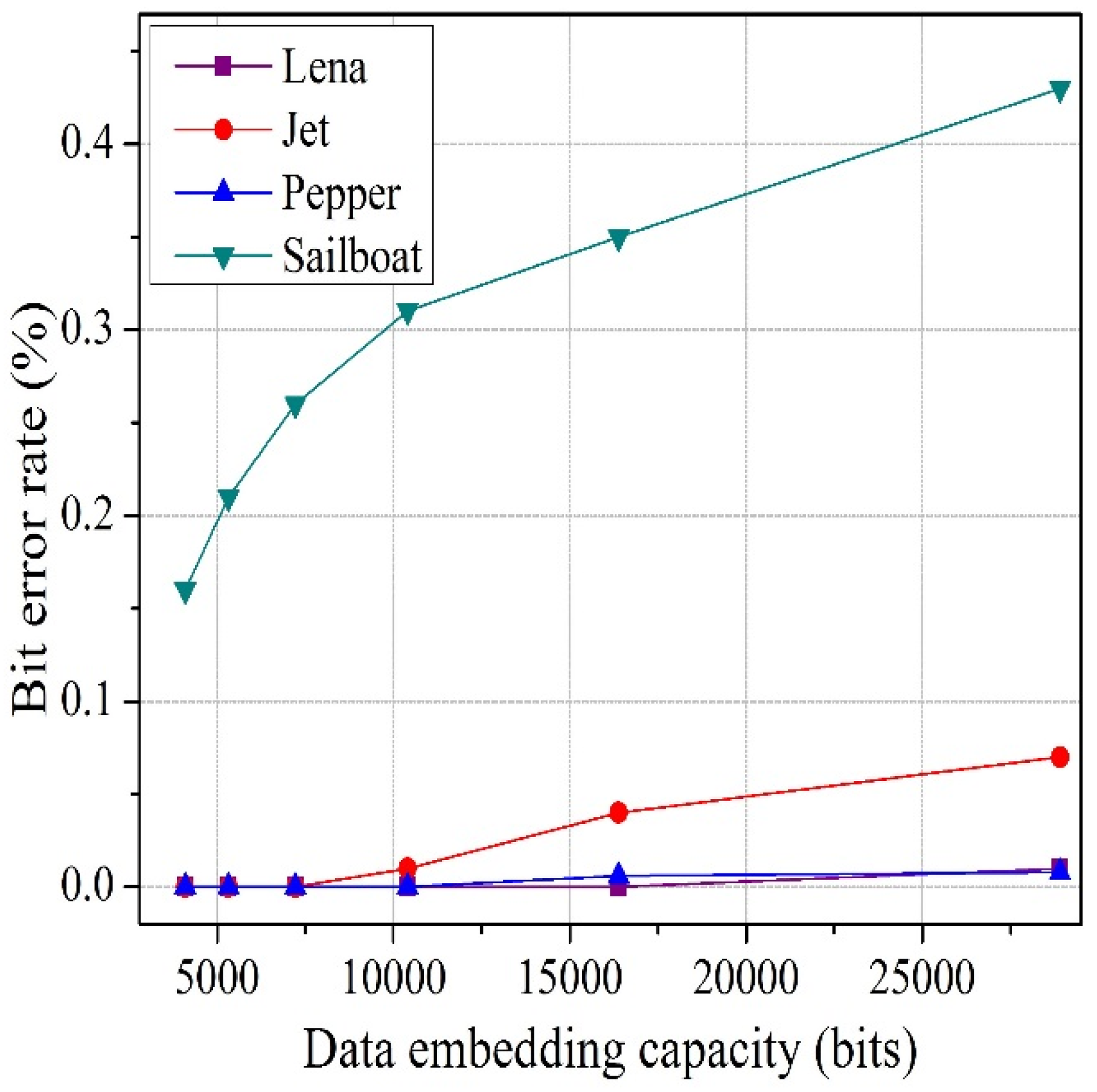
Figure 11.
BER comparison between the proposed system and the referenced systems for the test image Lena. (a) Comparison of systems mentioned. (b) Comparison of proposed system and Wu and Sun.
Figure 11.
BER comparison between the proposed system and the referenced systems for the test image Lena. (a) Comparison of systems mentioned. (b) Comparison of proposed system and Wu and Sun.
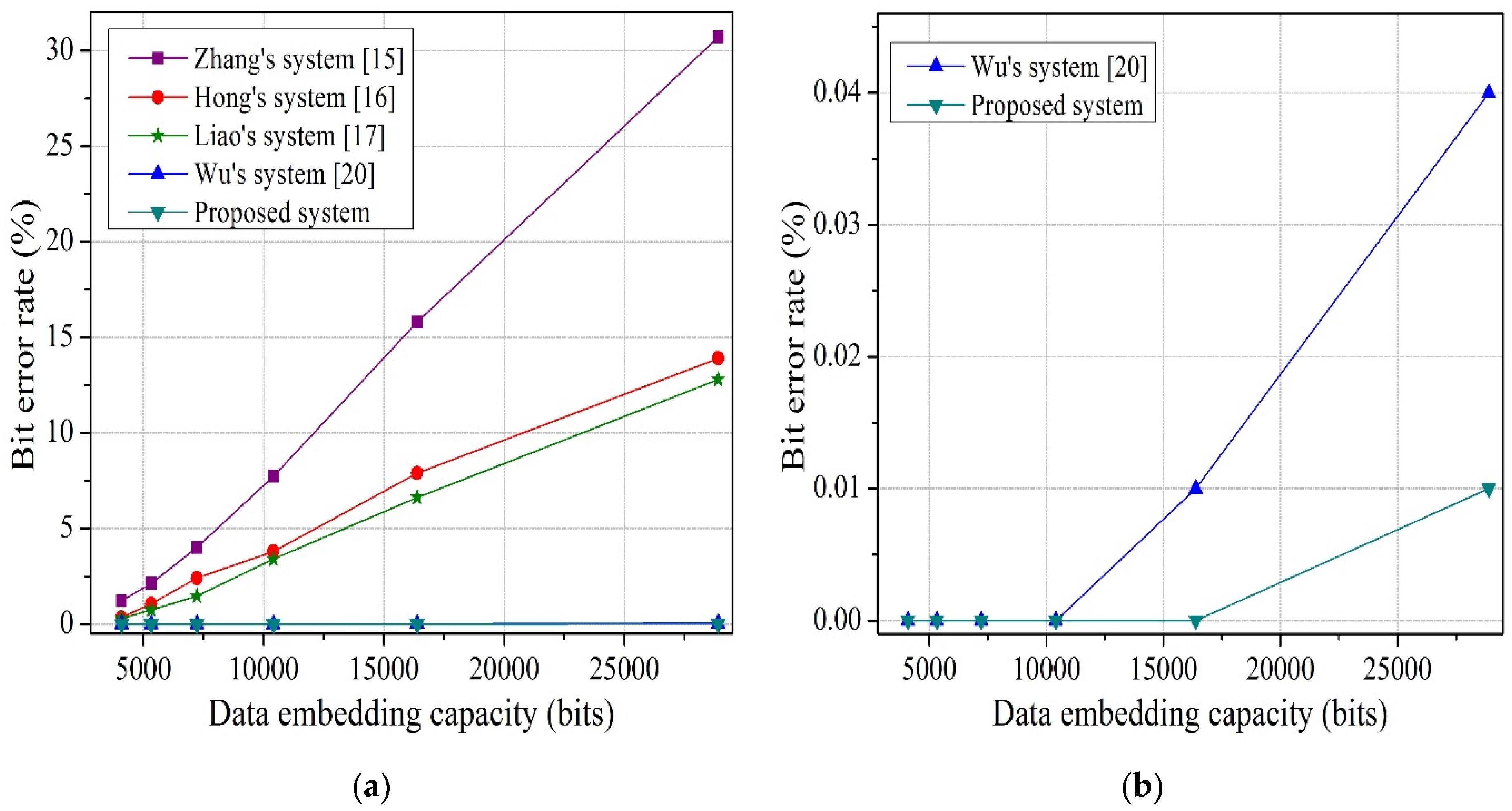
Figure 12.
BER comparison between the proposed system and the referenced systems for the test image Jet. (a) Comparison of systems mentioned. (b) Comparison of proposed system and Wu and Sun.
Figure 12.
BER comparison between the proposed system and the referenced systems for the test image Jet. (a) Comparison of systems mentioned. (b) Comparison of proposed system and Wu and Sun.
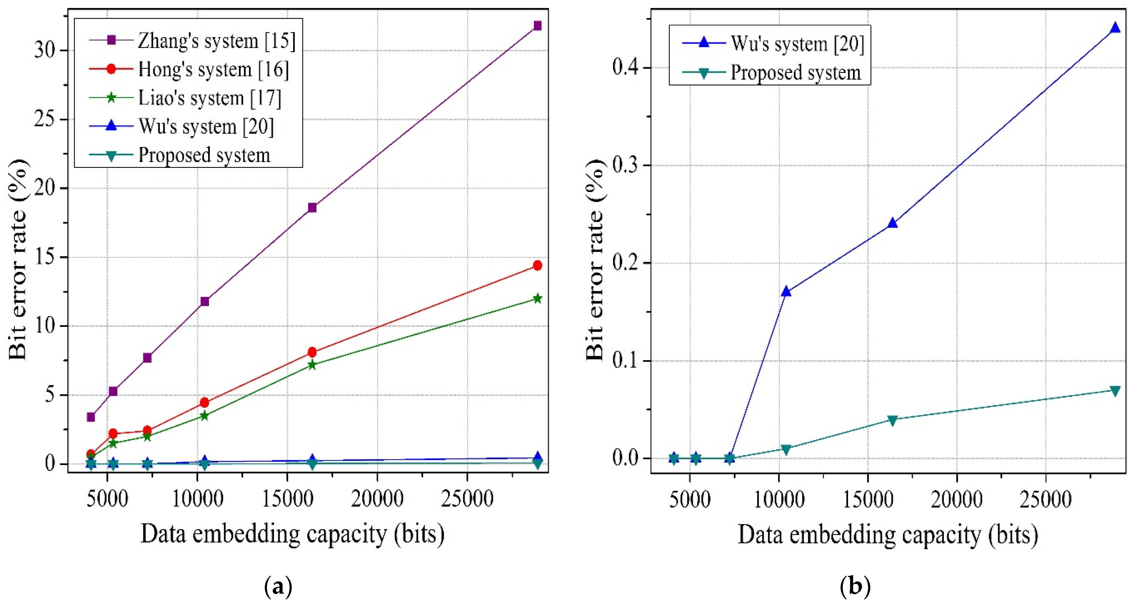
Figure 13.
BER comparison between the proposed system and the referenced systems for the test image Peppers. (a) Comparison of systems mentioned. (b) Comparison of proposed system and Wu and Sun.
Figure 13.
BER comparison between the proposed system and the referenced systems for the test image Peppers. (a) Comparison of systems mentioned. (b) Comparison of proposed system and Wu and Sun.

Figure 14.
BER comparison between the proposed system and the referenced systems for the test image Sailboat. (a) Comparison of systems mentioned. (b) Comparison of proposed system and Wu and Sun.
Figure 14.
BER comparison between the proposed system and the referenced systems for the test image Sailboat. (a) Comparison of systems mentioned. (b) Comparison of proposed system and Wu and Sun.
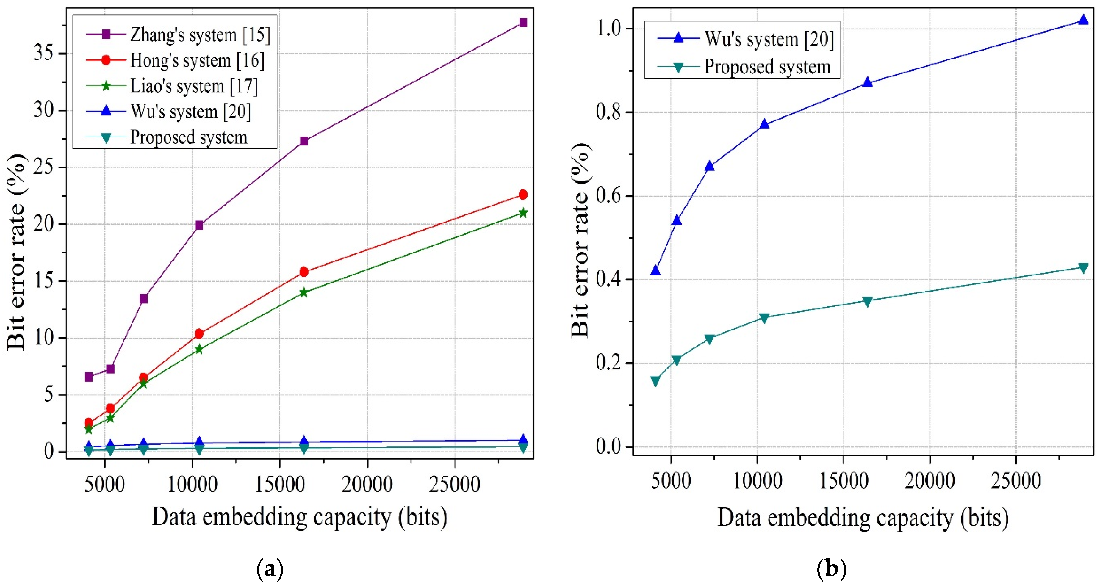
Figure 15.
Experiment by separable system. (a) Original Jet; (b) encrypted Jet containing information bits; (c) filtered decrypted Jet containing information bits; and (d) recovered Jet.
Figure 15.
Experiment by separable system. (a) Original Jet; (b) encrypted Jet containing information bits; (c) filtered decrypted Jet containing information bits; and (d) recovered Jet.

Table 1.
Performance analysis of the proposed system for the test image Lena.
| G | t | Embedded Bits | Embedding Rate (bpp) | Bit Error Rate |
|---|---|---|---|---|
| 10 | 5 | 4096 | 0.0156 | 0 |
| 4 | 6 | 4096 | 0.0156 | 0 |
| 15 | 5 | 7225 | 0.0275 | 0 |
| 4 | 6 | 7225 | 0.0275 | 0 |
| 4 | 6 | 16,384 | 0.0625 | 0 |
| 4 | 6 | 24,576 | 0.0938 | 0.008 |
| 4 | 6 | 28,900 | 0.1100 | 0.010 |
Table 2.
Performance analysis of the proposed system for the test image Jet.
| G | t | Embedded Bits | Embedding Rate (bpp) | Bit Error Rate |
|---|---|---|---|---|
| 10 | 5 | 4096 | 0.0156 | 0 |
| 4 | 6 | 4096 | 0.0156 | 0 |
| 15 | 5 | 7225 | 0.0275 | 0 |
| 4 | 6 | 7225 | 0.0275 | 0 |
| 4 | 6 | 16,384 | 0.0625 | 0.04 |
| 4 | 6 | 24,576 | 0.0938 | 0.05 |
| 4 | 6 | 28,900 | 0.1100 | 0.07 |
Table 3.
Performance analysis of the proposed system for the test image Peppers.
| G | t | Embedded Bits | Embedding Rate (bpp) | Bit Error Rate |
|---|---|---|---|---|
| 10 | 5 | 4096 | 0.0156 | 0 |
| 4 | 6 | 4096 | 0.0156 | 0 |
| 15 | 5 | 7225 | 0.0275 | 0 |
| 4 | 6 | 7225 | 0.0275 | 0 |
| 4 | 6 | 16,384 | 0.0625 | 0.006 |
| 4 | 6 | 24,576 | 0.0938 | 0.007 |
| 4 | 6 | 28,900 | 0.1100 | 0.008 |
Table 4.
Performance analysis of the proposed system for the test image Sailboat.
| G | t | Embedded Bits | Embedding Rate (bpp) | Bit Error Rate |
|---|---|---|---|---|
| 10 | 5 | 4096 | 0.0156 | 0.21 |
| 4 | 6 | 4096 | 0.0156 | 0.16 |
| 15 | 5 | 7225 | 0.0275 | 0.26 |
| 4 | 6 | 7225 | 0.0275 | 0.23 |
| 4 | 6 | 16,384 | 0.0625 | 0.35 |
| 4 | 6 | 24,576 | 0.0938 | 0.41 |
| 4 | 6 | 28,900 | 0.1100 | 0.43 |
Table 5.
PSNR (dB) comparison between the proposed system and the referenced systems for the test images.
Table 5.
PSNR (dB) comparison between the proposed system and the referenced systems for the test images.
| Test Images | Embedded Bits | Embedding Rate (bpp) | Zhang’s System [21] | Wu’s System [20] | Proposed Sytem |
|---|---|---|---|---|---|
| Lena | 4096 | 0.0156 | 65.89 | +∞ | +∞ |
| 16,384 | 0.0625 | 55.63 | +∞ | +∞ | |
| 40,960 | 0.1563 | 44.65 | +∞ | +∞ | |
| Jet | 4096 | 0.0156 | 60.14 | 60.17 | +∞ |
| 16,384 | 0.0625 | 48.66 | 60.17 | +∞ | |
| 40,960 | 0.1563 | 42.08 | 60.17 | +∞ | |
| Peppers | 4096 | 0.0156 | 56.14 | 51.14 | +∞ |
| 16,384 | 0.0625 | 41.01 | 45.17 | +∞ | |
| 40,960 | 0.1563 | 39.17 | 41.14 | +∞ | |
| Sailboat | 4096 | 0.0156 | 56.32 | 59.39 | +∞ |
| 16,384 | 0.0625 | 42.63 | 58.32 | +∞ | |
| 40,960 | 0.1563 | 39.88 | 54.84 | 57.16 |
© 2017 by the authors. Licensee MDPI, Basel, Switzerland. This article is an open access article distributed under the terms and conditions of the Creative Commons Attribution (CC BY) license (http://creativecommons.org/licenses/by/4.0/).
Share and Cite
MDPI and ACS Style
Khanam, F.-T.-Z.; Kim, S. Enhanced Joint and Separable Reversible Data Hiding in Encrypted Images with High Payload. Symmetry 2017, 9, 50. https://doi.org/10.3390/sym9040050
AMA Style
Khanam F-T-Z, Kim S. Enhanced Joint and Separable Reversible Data Hiding in Encrypted Images with High Payload. Symmetry. 2017; 9(4):50. https://doi.org/10.3390/sym9040050
Chicago/Turabian StyleKhanam, Fatema-Tuz-Zohra, and Sunghwan Kim. 2017. "Enhanced Joint and Separable Reversible Data Hiding in Encrypted Images with High Payload" Symmetry 9, no. 4: 50. https://doi.org/10.3390/sym9040050
Note that from the first issue of 2016, this journal uses article numbers instead of page numbers. See further details here.