
Reversible Data-Hiding Systems with Modified Fluctuation Functions and Reed-Solomon Codes for Encrypted Image Recovery


School of Electrical Engineering, University of Ulsan, Ulsan 44610, Korea
Symmetry 2017, 9(5), 61; https://doi.org/10.3390/sym9050061
Submission received: 29 March 2017
/
Revised: 15 April 2017
/
Accepted: 21 April 2017
/
Published: 25 April 2017
(This article belongs to the Special Issue Symmetry in Secure Cyber World)
Abstract
:In this paper, reversible data-hiding (RDH) systems with modified fluctuation functions and rate-matched Reed–Solomon (RS) codes are proposed to enhance the data recovery from encrypted images. The modified fluctuation functions are used for estimating embedded codeword bits from the correlation of pixels. Instead of direct data-bit embedding, codeword bits of RS codes are embedded by a data-hider. With the help of the error-correcting capability of RS codes, the encrypted message can be recovered from the weak correlation of adjacent pixels in the image. In the experimental results, bit error rate (BER) and peak signal to noise ratio (PSNR) performances of the proposed system are better than those of referenced data-hiding systems for three images. The proposed schemes based on the modified fluctuation function or rate-matched codes can be applied to various RDH systems with better data transmission and image recovery performance.
1. Introduction
Data-hiding has a long history and has been widely used for information security for centuries. Moreover, a good review of the recent works appeared in [1], which classified modern data-hiding techniques and cryptography as two distinguishable domains for information security and explained comprehensive analysis of information-hiding techniques. An interactive buyer-seller watermarking protocol has been proposed to not allow invisible watermarked copy [2], and a secure comparison protocol in the encrypted domain was also proposed [3].
New techniques to hide information in encrypted images have drawn much interest of researchers who have extended its applications. Data-hiding in encrypted images involves several different problems since it is impossible to directly use the contents of encrypted data. Therefore, applications of data hiding in the encrypted images have been explained in a number of papers [4,5,6,7,8,9,10,11,12,13,14,15,16,17,18,19,20,21,22,23]. The usage of an encrypted image as the cover medium for concealing data is not only a relatively new research subject, but an interesting subject due to simultaneous consideration of both cryptography and steganography technology, which have been independently developed. An encrypted image can be protected when it is transmitted through a public channel, increasing the difficulty of analyzing the embedded data.
Among data-hiding technologies, reversibility is one of the major research topics since an encrypted image should be recovered to the original image after extracting the hidden data. Reversible data-hiding (RDH) systems are designed to assign embedded data to a cover media and to allow recovery of the original image without distortion after extraction. Especially, for military and medical images, which are important applications of data-hiding, there should be no distortion in the recovered image due to data hiding.
The embedding procedure of the RDH systems with flipping least significant bit (LSB) is first to divide an encrypted image into blocks and to use the LSBs of pixels in the blocks according to the embedded data. In the receiver, spatial correlation in the natural digital image is calculated to estimate the embedded data. Zhang [4] first proposed RDH systems with flipping LSBs and suggested the fluctuation function by using the four neighboring pixels to measure the spatial correlation between pixels in each block. Hong’s system [5] separately calculated the horizontal and vertical fluctuations of the correlation. Moreover, Hong [5] proposed a side-match technique that the updated border of neighboring blocks be used for calculating the correlation in order to improve the spatial correlation, whereas the marginal pixels of the block are not used in [4]. Modified fluctuation functions were proposed according to the position of pixels in block [6], and the functions were composed of three different equations. Reversible data hiding systems were proposed by using a new embedding pattern and multiple judgments [8]. These RDH systems perfectly recovered the original image if there was no error in the extracted data.
The RDH about lossless data compression are based on data compression to make new space for the data hider to hide data. Research about lossless data compression was designed to develop efficient data compression to reduce image distortion. In [7], a separable RDH scheme for encrypted images was proposed by compressing the encrypted data using a source coding scheme with side information, making data extraction independent of encryption. An efficient data compression from low-density parity-check codes was proposed, and a new data extraction method using side information was discussed in [9] to enhance rate-distortion performance. In [10,11], the recursive code construction for binary covers was improved, and it was shown that the construction can achieve the rate-distortion bound. To improve RDH schemes based on the distortion matrices, a system estimating the optimal transition probability matrix for a general distortion matrix was proposed in [12].
In the RDH system with histogram shift, the histogram was first produced by the error value between original pixels and estimated pixels. According to embedded data and the error value, the error histogram was shifted for saving space for data embedding by shifting the bins of the histogram. In [13], the RDH based on the histogram of the prediction vector quantization-compressed image was proposed where the index of the image was used for embedding. Similarly, Ma [14] proposed RDH systems for encrypted images by reserving room, where the original image was divided into two partitions and the LSBs of one partition were embedded into the other partition by a traditional RDH algorithm [18]. In [15], generating RDH codes according to the theoretical expressions [19] of RDH were determined by the differences between the original pixel-values and the corresponding values estimated from the neighbors. An efficient RDH method was proposed by estimating pairwise prediction errors and modifying the 2D histogram of the prediction-errors in [16]. Recently, Zhang [17] proposed a combination method with a histogram modification and lossless data compression by using an entropy coder.
Recently, modified RDH systems were proposed to have better performance. Data hiding by using zero coefficient quantization table was proposed in JPEG images [20]. Hussain et al. [21] introduced a hybrid data hiding method combining the right-most digit replacement (RMDR) with an adaptive least significant bit (ALSB) for digital images. Kumar et al. [22] proposed RDH based on prediction error and expansion based on adjacent pixels. Hong et al. [23] proposed a new data-hiding technique for absolute moment block truncation coding (AMBTC) of a compressed image based on quantization level modification. Improved embedding pattern and a new measurement function were proposed in encrypted images with a high payload to enhance transmission performance [24]. One vacating room before encryption was proposed in encrypted image, where the content owner creates room for embedding data in the cover image before encryption [25]. Qian et al. [26] proposed a novel scheme of RDH in encrypted images using distributed source coding to protect the secrecy of the system. Xiao et al. [27] proposed a separable RDH technique in encrypted images based on the pixel value ordering where homomorphism encryption is used for image encryption.
The Reed–Solomon (RS) codes are named for their inventors who published the codes in 1960. RS codes have good error-correction capability for bursty errors since they are non-binary cyclic maximum distance separable codes. Therefore, they have been widely used in consumer electronics, data transmission technologies, broadcast systems, optical communications and image processing systems. During the past decades, research about RS codes has been updated quickly. The Berlekamp–Massey (BM) algorithm [28] is an efficient hard decoding algorithm of RS codes that uses a linear feedback shift register (LFSR) to determine error location polynomials with the smallest degree and error locations by solving the roots of the polynomials. A new run-length-limited decoding algorithm to increase the performance of RS codes in a visible light communication system has been proposed [29].
In this paper, efficient reversible data-hiding systems are proposed by using new fluctuation functions and rate-matched RS codes. The estimated bits of the fluctuation functions are more correct since boundary pixels and average distance are used for calculation. With the help of the error-correcting capability of RS codes, the embedded message can be recovered correctly. In order to efficiently correct the errors according to weak spatial correlation, RS codes based on the BM algorithm are considered for decoding. In the bit error rate (BER) results of three different images, our proposed system showed better performances than the data-hiding systems. Peak signal to noise ratio (PSNR) performances were also shown in the experimental results. To check the performance enhancements, fundamental RDH systems are considered as referenced systems, but our fluctuation functions or coding schemes can be applied to recently-published RDH systems with modifications.
2. System Model of the Proposed Scheme
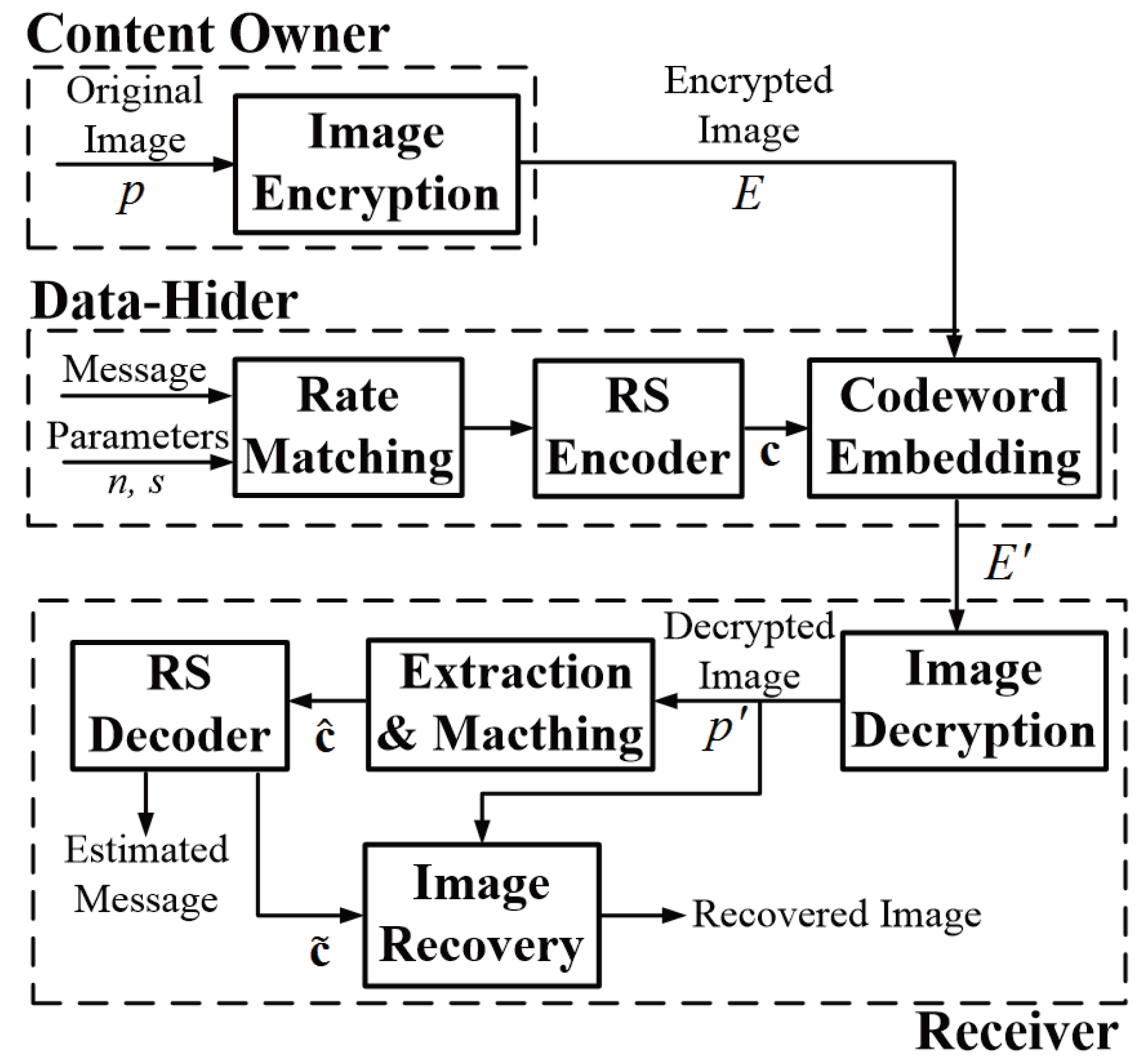
The proposed data-hiding system is shown in Figure 1. First, a content owner encrypts the original uncompressed image using an encryption key and creates an encrypted image. Then, a data-hider produces codewords from the data using an RS encoder and embeds the codewords into the encrypted image using a data-hiding key. The two different images, the encrypted image E and the codeword-embedded image , are created, and the codeword-embedded image is transmitted to the receiver. The content owner and the data-hider can be the same or different entities. When the data-hider is different from the content owner, the data-hider does not know the original image, but the data-hider can embed data in the encrypted image. In a receiver, the encrypted image containing additional data is decrypted using the encryption key. According to the data-hiding key, the estimated values for the embedded codeword are extracted, and the hidden data must be recovered after decoding the RS codes. From the help of the error-correction capability of the RS codewords, performance for recovering the image can be enhanced.
2.1. Image Encryption
The method of image encryption in this paper is similar to that in Zhang’s system [4]. It is assumed that the original image consists of pixels with their gray values [0, 255], which are represented by eight bits. Let the size of the original image and the gray value be pixels and , respectively, where for and denotes the position of the pixel. In the encryption phase, the pixels are encrypted through the bitwise exclusive-or (XOR) operations of the original pixel . It is assumed that pseudo-random values are generated by the encryption key. Then, the encrypted image for pixel is determined as:
2.2. Rate Matching and RS Encoder
For data transmission, codewords of RS codes are embedded in order to correct errors instead of directly embedding data in encrypted images. For data hiding, the encrypted image is segmented into a number of non-overlapping blocks sized . Then, the maximum number of blocks, , that can be embedded in an encrypted image is . Therefore, in rate matching, the generated message sequence is needed for embedding the codeword. To explain this process, the RS code parameter should be discussed.
RS codes [28] are defined in a Galois field, GF, where q is a positive integer. Then, the parameters of RS codes with length n and dimension k are defined as , where denotes the maximum number of symbol errors that the RS decoder can correct. The code rate of RS codes are defined as . It is known that the message and codeword of RS codes can be expressed as:
where and are a message polynomial and a codeword polynomial, respectively. The generator polynomial is defined as:
where is a primitive element of GF(). The encoding for systematic RS codes is defined as:
where is the parity polynomial with degree and is a remainder polynomial when is divided by .
The maximum number of codewords, , in the encrypted image is . In the ‘rate matching’ in Figure 1, the ()-bit message is the input for the RS encoder. The remaining bits are zero-padded. The choice of codes parameter and block size s in the proposed system is determined by the capability of data recovery. The s is dependent on the calculation of spatial correlation, and the difference of the correlation for each data increases as the size s increases. The increase of s leads to enhanced data recovery, but it needs to reduce room for data-hiding in the encrypted image. When the code rate of RS codes decreases, the error correcting capability of the RS codes is enhanced since the of RS codes increases. The decreasing code rate also leads to better data recovery, but transmission efficiency also becomes worse. Since the data recovery in the proposed systems is strongly related to image recovery, the choice of parameters for better data-recovery are required according to the purpose or environment of the systems. Therefore, discussion about the proper design of the size of s and code parameters is needed, and the analysis of performance according to code rate and the size of s is explained in the Experimental Results.
2.3. Codeword Embedding
Using the codewords of RS codes, a data-hider can embed codewords into the encrypted image. Let be the v-th codeword for , where is an element of . There exists a bijection mapping B between an element in GF and q elements in GF(2) according to a primitive polynomial of GF. Therefore, the binary bit can be determined from an element of GF by the bijection function as:
where for and GF(2) for . The mapping can be applied to codeword as:
Then, the total concatenation of all binary codeword bit is expressed as:
The -bit sequence can be defined as:
where is a permutation function. To apply to the block array, , an element of the a-th row and the b-th column in is mapped from the -th element of as:
where and .
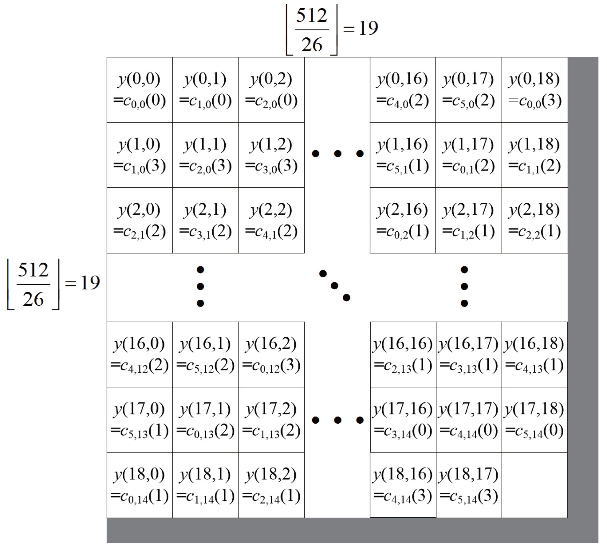
In Figure 2, an example of codeword embedding is shown. The size of the image and s is assumed as and 26, respectively. The length of RS codes is assumed as . Then, and are determined as 361 and six, respectively. The gray rectangles denote the region that does not contain embedded codeword bits in the image. A square in Figure 2 denotes one block with pixels. The square in the a-th row and b-th column array can embed one bit denoted as . The permutation function in (4) is considered as the simple rearrangement of codeword bits of in (3) according to incremental orders of v, t and l in (1)–(3).
In the block, the encrypted pixel , which satisfies , , exists within the same block, where are non-negative integers. For each block, the pixels are pseudo-randomly divided into two sets, and , uniformly distributed according to a data-hiding key. The is embedded into the block by flipping w LSBs in the group, which are determined by the value of the codeword bit. If the is zero, the w LSBs of each encrypted pixel in are flipped. Similarly, if the is one, the w LSBs of pixel in are flipped. Let be a function for flipping w LSBs of an encrypted pixel. For example, the function for flipping three LSBs, , is expressed as:
The encrypted pixel with embedded codeword bits, , can be represented as:
where .
3. Fluctuation Function and Decoding of the Proposed System
Receivers in the proposed data-hiding systems are composed of four steps: image decryption, codeword extraction and matching, RS decoder and image recovery.
3.1. Image Decryption
It is assumed that the receiver knows both the encryption key and the data-hiding key. The receiver first generates the , which was already used for the encrypted image, according to the encryption key, and the decrypted pixel is calculated by taking the XOR of the received signal in (7) and . That is, for , , is calculated as:
If is the same as , can be expressed as:
where is a value by flipping w LSBs of the original pixel . Therefore, the decrypted pixel can be expressed as:
3.2. Codeword Extraction and Matching
In order to extract the codeword bit that is embedded in a block located in the a-th row and b-th column, and for , are calculated as:
If the codeword bit is zero, is the same as , but is according to (8) and (9). Similarly, if the codeword bit is one, then is the same as , but is according to (8) and (10). In each block, this means that is the same as if a is the same as the codeword bit; otherwise, is w LSBs flips of . The hidden codeword bits are determined by comparing each fluctuation function and have the lower value of the fluctuation function due to spatial correlation in natural images.
We consider the two fluctuation functions to determine hidden codeword bits: Zhang’s fluctuation function [4] and Hong’s fluctuation function [5]. The first fluctuation functions, and , are calculated as:
Hong’s fluctuation functions, and , are represented as:
For calculating the fluctuation function, the distance from the average value from neighboring pixels is used to find the the difference when the w LSBs in the pixels are flipped. In Zhang’s fluctuation functions (11) and (12), the distance from the average value is calculated. However, the distance of boundary pixels in each block is omitted. Especially, for small s, the value of the fluctuation function is small, and estimation from the fluctuation functions becomes worse. For example, , pixels can be used to determine the fluctuation functions. In contrast, boundary pixels in the left or upper corner are included in Hong’s fluctuation functions (13) and (14). However, the distances from neighboring lower and right pixels are used, and large vertical or horizontal distance is dominant. Therefore, a small number of pixels in each block can be dominant to calculate the fluctuation functions when the pixels are widely different from neighboring pixels.
To utilize the two fluctuation functions, the new fluctuation functions, and , are proposed as:
In the proposed fluctuation functions, and , vertical and horizontal average value and boundary pixels for calculating the distance are used. Moreover, pixels in the right and left corner are used to determine the distance from the horizontal average, and similarly pixels in the top and bottom corner are used to determine the distance from the vertical average. In the Experimental Results, the performance comparison among three fluctuation functions will be discussed.
Let be one of the fluctuation functions (11), (13), (15), and similarly, let be one of the fluctuation functions (12), (14), (16). Then, if the is smaller than the , the corresponding codeword bit is zero. If otherwise, the corresponding codeword bit is one. Therefore, the estimated bit embedded into the block, , is given as:
The estimated bit corresponds to in (5). Then, the -th element of can be defined as:
The length of is . From the permutation in (4), is defined as:
where is the inverse function of . By using the mappings and in (3), (2) and (1), the estimated codeword for can be determined as:
where and are inverse mappings of and , respectively, and denotes the vectors with from the i-th elements to the j-th elements in .
3.3. RS Decoder
In the output of data extraction, there might exist errors in the estimated codewords, for which the RS decoder can be used for error correction. Among RS decoding algorithms, the BM algorithm [28] and Forney algorithm [30] are considered in the proposed systems. Let be one of for and be the polynomial form of . Then, the polynomial can be expressed as:
where is an element of GF. The received polynomial can be regarded as the summation of a codeword polynomial and an error polynomial :
To determine error locations and values, syndromes for are calculated as:
where is a primitive element in GF, for and . Let the error location polynomial be defined as:
where u is the number of errors and . There is a relation between syndromes and the coefficients of error location polynomials:
In the BM algorithm, coefficients of the error location polynomial are determined from (20) and (21). LFSR can be used for the implementation to calculate the coefficients. Then, error locations can be found by solving the roots of the polynomial.
Forney’s algorithm [30] utilizes each error location to determine corresponding error values. Before the error values are computed, two necessary definitions, syndrome polynomial, , and error evaluator polynomial, , are established using (18), and they are defined as:
The error values, , are computed as:
where is the derivative of (19) and w is from zero to . The error polynomial, , is computed using (20), (21) and (22), and then, we determine the RS codeword, , using the error polynomial.
After decoding of codewords, recovered codewords for are calculated. Since systematic RS codes are considered, the recovered messages are obtained by concatenating bits of the recovered codewords.
3.4. Image Recovery
The inputs of image recovery are recovered codewords and decrypted pixels . The recovered codeword bits are calculated by applying the process from (1) to (5) where recovered codewords are used instead of . From the decrypted pixels calculated in image decryption, the recovered pixels are expressed as:
where and is an element on the a-th row and the b-th column in .
The PSNR can be used for evaluating the image recovery performance and can be defined as:
where MAX denotes the maximum value of pixels in the image and MSE is the mean squared error defined as:
If the MSE is zero, the PSNR is infinite.
4. Experimental Results
In this paper, the three gray-scale Lena, Peppers and Jet images, shown in Figure 3, are considered. The size of the three gray images is . The range of the block size s is from six to 38, which was already considered in [4,5]. The function to flip w LSBs is considered as , which is shown in (6).
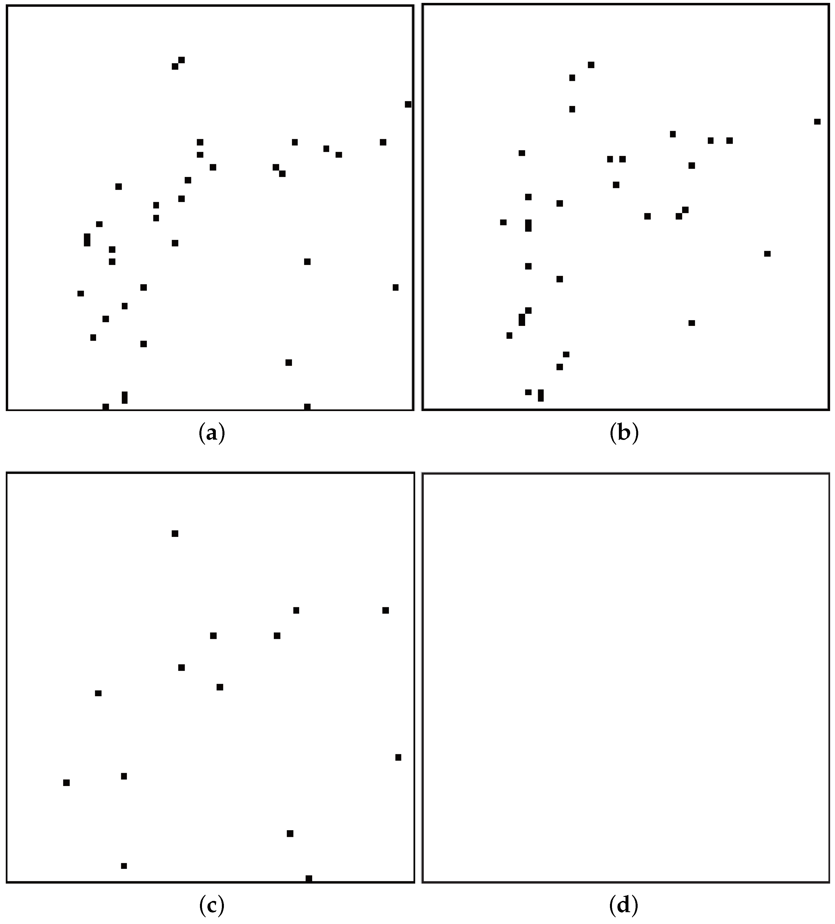
To compare the proposed data-hiding systems with the referenced systems, the error pattern of the data-hiding system is shown in Figure 4. For a Lena image and , error positions of Zhang’s system [4], Hong’s system [5], the proposed system with fluctuation functions in (15) and (16) and the proposed system with the fluctuation function and RS(15,11) codes are shown in (a), (b), (c) and (d) in Figure 4, respectively. The small black square in a large square in Figure 4 denotes error pixels in a Lena image. From Figure 4a to Figure 4c, the recovery performance of the system with the proposed fluctuation functions in (15) and (16) is better than the ones of Zhang’s system [4] and Hong’s system [5] for s = 8 and the Lena image. Moreover, there is no error pattern in (d) of Figure 4 when the proposed system with RS(15,11) codes is used.
To investigate how RS codes can help recover the error in RDH systems, an example for the proposed system with RS codewords is shown in Figure 5. Figure 5a is similar to Figure 4c. One error in Figure 5a is located at . It is assumed that the codewords of RS(15,11) start from and are assigned to the right sequentially. Then, the error at belong to the 11th codeword, which starts at and ends at . The gray rectangle in Figure 5a denotes the 11th codeword, and the codewords are also shown in Figure 5b. The codeword is composed of 15 symbols, which corresponds to 60 bits. A blue rectangle in Figure 5b denotes a symbol of codewords. From Figure 5b, one symbol of the codeword is an error, and it is known that RS(15,11) can correct up to two error symbols. Therefore, the error pattern at can be recovered from the RS codes. Similarly, the other errors can be recovered by the help of RS codes.
In Figure 6, the BER performances of the referenced systems and proposed system without RS codes are shown according to the size of s when the Lena, Peppers and Jet image in Figure 3 are considered. The ‘Ref. Zhang [4]’ and ‘Ref. Hong [5]’ in these figures denote BERs for Zhang’s scheme in [4] and Hong’s scheme in [5], respectively. The ‘Pro. Fluc.’ in these figures stands for BERs for the proposed fluctuation functions in (15) and (16). In Figure 6, as block size s increases, the BERs of two referenced system sand the proposed system without RS codes become better. BER performances of two referenced systems and the proposed system without RS codes in Figure 6a,b are better than BER performances in Figure 6c, since the Jet is a weakly correlated image. In Figure 6a,b, BER performances of the proposed fluctuation function are always better than the referenced systems. It is shown that the proposed fluctuation functions are effective for the RDH system without the help of RS codes. In Figure 6c, the BER of the proposed system without RS codes is the same or better than the BER of Zhang’s system. For a small length of s, the BERs of three systems turn around since the reliability of the fluctuation function in the weakly correlated image is small. For some value of s, the BER of Zhang’s system is better than the BER of the proposed system without RS codes, since the embedding process is different, and the fluctuation functions in Zhang’s system are based on the difference of neighboring pixels.
To investigate the performances of the proposed systems with RS codes, four RS codes are used, which are an RS(15, 11), an RS(15, 7), an RS(31, 23) and an RS(31, 15) code in this simulation. The code rates of the four RS codes are 0.73, 0.47, 0.74 and 0.48, respectively, and they correspond to around 1/2 and 3/4. The lengths of the codes are 15 and 31. These RS codes can be used for estimating the performance change according to the length and rate of RS codes.
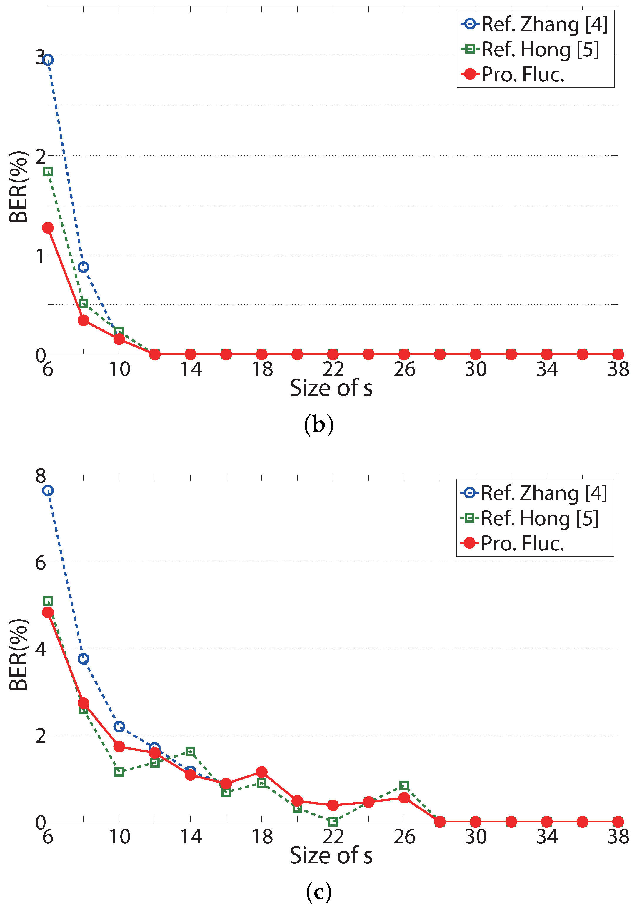
In Figure 7, BER performances of the referenced systems and the proposed systems are shown according to the size of s when the Lena, Peppers, and Jet images in Figure 3 are considered. The ‘Ref. Zhang [4]’ and ‘Ref. Hong [5]’ in these figures also denote BERs for Zhang’s scheme in [4] and Hong’s scheme in [5], respectively. The notations ‘Pro. RS(15, 11),’ ‘Pro. RS(15, 7),’ ‘Pro. RS(31, 23),’ and ‘Pro. RS(31, 15)’ represent the proposed systems with RS(15, 11), RS(15, 7), RS(31, 23) and RS(31, 15) codes, respectively. For most values of s, the BER performances of the proposed systems with four RS codes are better than those of the referenced systems [4,5]. In Figure 7c, it is shown that the BER performance of RS(15, 11) fluctuates as s increases, since the RS codes can correct up to two error symbols. For s = 14, 18 and 20, there are less than three error symbols in every codeword of RS(15, 11) codes, and the BER is zero. In Figure 7a,b, the BER of the proposed system is 0 for , though the BER of the referenced systems [4,5] is non-zero. In Figure 7c, BERs of the proposed systems with RS(15,7) and RS(31,15) codes are better than the two referenced systems. If s is larger than or equal to 10, BERs of the two proposed systems are zero over the weakly correlated image. For high rate RS codes, such as RS(15,11) and RS(31, 23), BER performances in Figure 7c turn around as s increases, since the image is weakly correlated, and the error capability of the codes is small.
Since the proposed systems consider RS codes with code rates of 0.75 and 0.5, the transmission efficiencies of the proposed systems are less than those of the referenced systems. Therefore, for fixed BER, the effective length of the embedded message must be considered for proper transmission. For fair comparison, the number of messages for BER = 0 is considered, where BER = 0 means that embedded messages are extracted without error. The main results of the proposed systems and the referenced systems [4,5] are listed in Table 1, Table 2 and Table 3 for BER = 0 when the Lena, Peppers, and Jet images are considered, respectively. The ‘Ref. Zhang [4],’ ‘Ref. Hong [5],’ and ‘Pro. RS(15, 11), Pro. RS(15, 7), Pro. RS(31, 23), Pro. RS(31, 15),’ in Table 1, Table 2 and Table 3 correspond to the referenced systems [4,5] and the proposed system with RS(15, 11), RS(15, 7), RS(31, 23) and RS(31, 15) codes, respectively. The ‘Rate’ in these tables denotes the code rates of the considered systems; since the referenced systems have no RS codes, their code rates are one. The ‘Min. s’ in these tables stands for the minimum size of s that guarantees BER = 0. The ‘No. messages’ in these tables denotes the number of actual embedded messages corresponding to minimum s. The ‘Gain’ in these tables denotes the ratio of message length of the proposed systems to the message length of the referenced system and is written as a percentage. The ‘G1’ and ‘G2’ are gains when the referenced systems are those in [4,5], respectively.
As can be seen in Table 1, Table 2 and Table 3, the minimum s of the proposed systems is always smaller than that of the referenced systems. The number of embedded messages in the proposed systems is also larger than that in the referenced systems. In Table 1, when the Lena image is considered, the proposed systems with an RS(15, 11) code and an RS(31, 23) show about three times more efficient transmission than the referenced system [4]. In Table 3, the proposed systems with an RS(15, 7) code and an RS(31, 15) are more than two times more efficient than the referenced systems [4,5].
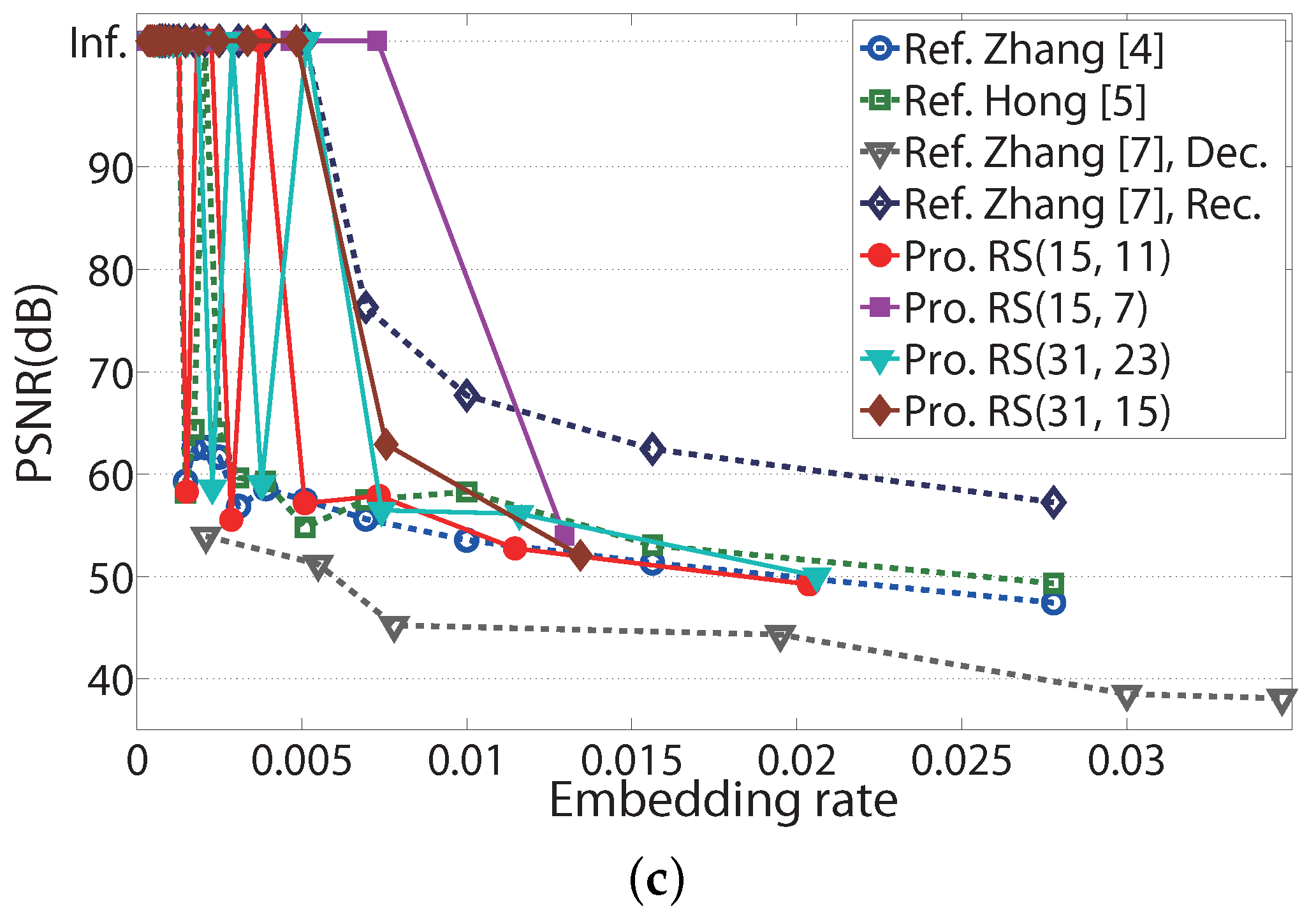
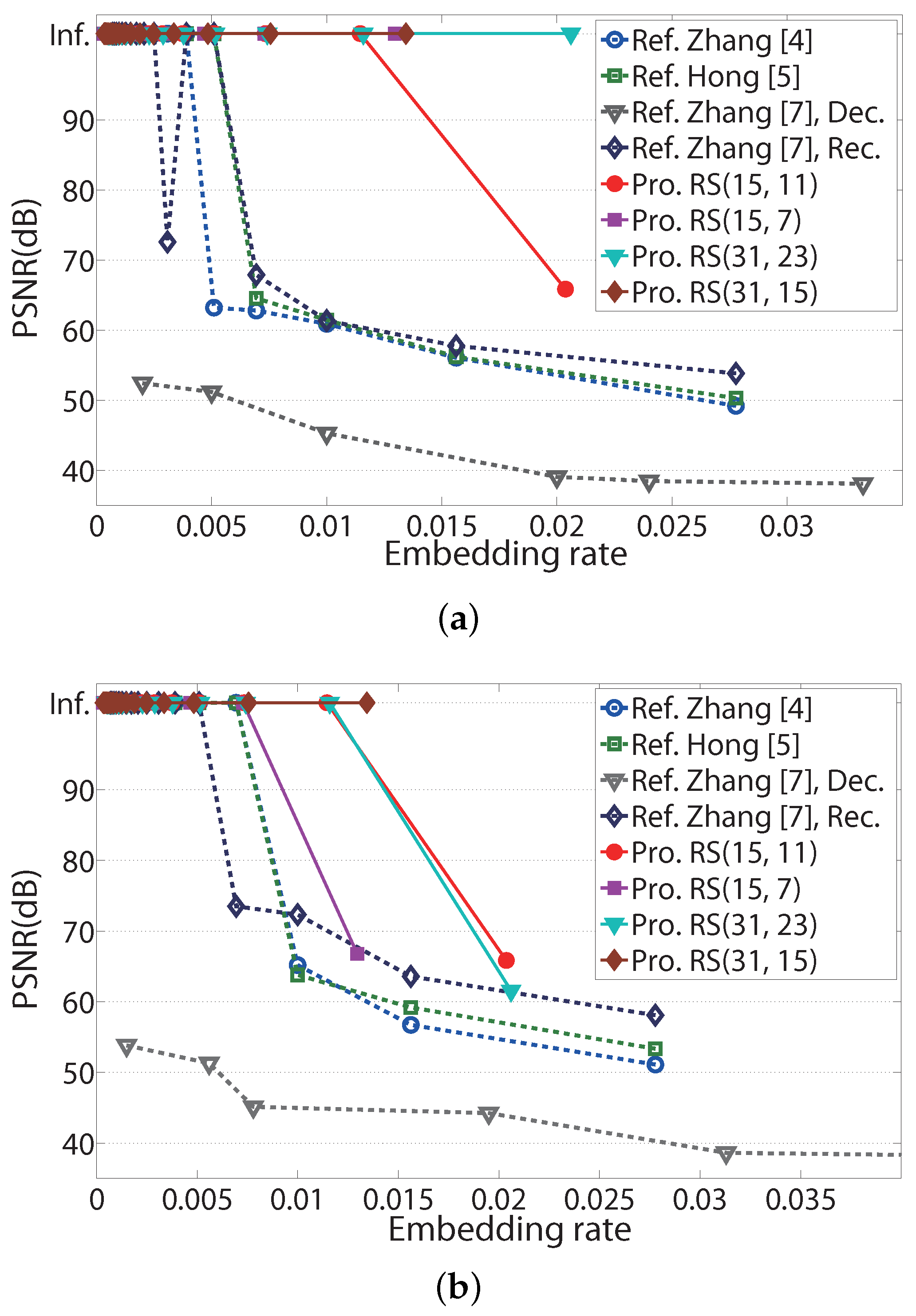
To verify the performance of image recovery, PSNR performances for the three images in Figure 3 according to the embedding rate are shown in Figure 8. The ‘Embedding rate’ in Figure 8 represents the ratio of the number of embedded messages to the number of pixels in an embedded image. The ‘Inf.’ in Figure 8 denotes infinite PSNR. Infinite PSNR cannot be illustrated in these figures; however, for convenience, it is located at 103.4 dB, the MSE of which corresponds to (≈). Since the pixels in the images are represented with eight bits, MAX in (24) is 255. The ‘Ref. Zhang [7], Dec.’ and ‘Ref. Zhang [7], Rec.’ in Figure 8 denote PSNRs in directly decrypted image and recovered image of Zhang’s scheme in [7], respectively. M and S, which represent the number of LSBs of pixels and the number of hidden data per a group in [7], are considered as two and one, respectively. The PSNRs in directly decrypted images and in recovered images represent those before image recovery and after image recovery in [7], respectively, and PSNR performances in directly decrypted images were shown in [7].
In Figure 8, most embedding rates of the proposed systems are higher than those of the referenced systems, which satisfy the infinite PSNR. In Figure 8a, the proposed scheme with RS(31, 23) codes has an embedding range up to 0.02, which guarantees an infinite PSNR, while the referenced systems have an embedding range up to 0.007. Similarly, in Figure 8b, the proposed scheme with RS(31, 15) codes has an embedding range up to 0.014 for infinite PSNR.
5. Conclusions
In this paper, improved data-hiding systems based on modified fluctuation functions and RS codes are proposed for efficient data recovery. The proposed fluctuation functions show enhanced estimation performance than referenced functions. The error-correcting capability of RS codes can be used to improve the weak correlation of adjacent pixels in data-hiding systems. The BER and PSNR performances in the experimental results show that the proposed systems are more effective than the referenced systems. For fair comparison, the number of messages of the proposed systems and referenced systems is calculated for zero BER, and embedding rates are also discussed for infinite PSNR. It is verified that the proposed data-hiding systems show more efficient data transmission and image recovery than the referenced fundamental RDH systems. Our approaches started from the fundamental RDH systems, but the proposed fluctuation functions or coding scheme can be applied to recent RDH systems with modification for performance enhancement.
Acknowledgments
This research was supported by Basic Science Research Program through the National Research Foundation of Korea (NRF-2014R1A1A1004521, NRF-2016R1D1A1B03934653).
Author Contributions
All authors discussed the contents of the manuscript and contributed to its presentation. Sunghwan Kim designed and implemented the proposed scheme, analyzed the simulation data and wrote the paper.
Conflicts of Interest
The authors declare no conflict of interest.
References
- Cheddad, A.; Condell, J.; Curran, K.; McKevitt, P. Digital image steganography: Survey and analysis of current methods. Signal Process. 2010, 90(3), 727–752. [Google Scholar] [CrossRef]
- Memon, N.; Wong, P.W. A buyer-seller watermarking protocol. IEEE Trans. Image Process. 2001, 10, 643–649. [Google Scholar] [CrossRef] [PubMed]
- Zhao, B.; Delp, E.J. Secret sharing in the encrypted domain with secure comparison. In Proceedings of the Global Telecommunications Conference (GLOBECOM 2011), Houston, TX, USA, 5–9 December 2011; pp. 1–5. [Google Scholar]
- Zhang, X. Reversible data hiding in encrypted images. IEEE Signal Process. Lett. 2011, 18(4), 255–258. [Google Scholar] [CrossRef]
- Hong, W.; Chen, T.-S.; Wu, H.-Y. An improved reversible data hiding in encrypted images using side match. IEEE Signal Process. Lett. 2012, 19(4), 199–202. [Google Scholar] [CrossRef]
- Liao, X.; Shu, C. Reversible data hiding in encrypted images based on absolute mean difference of multiple neighboring pixels. Vis. Commun. Image Represent. 2015, 28, 21–27. [Google Scholar] [CrossRef]
- Zhang, X. Separable reversible data hiding in encrypted image. IEEE Trans. Inf. Forensics Secur. 2012, 7, 826–832. [Google Scholar] [CrossRef]
- Pan, Z.; Wang, L.; Hu, S.; Ma, X. Reversible data hiding in encrypted image using new embedding pattern and multiple judgments. Multimed. Tools Appl. 2016, 75, 8595–8607. [Google Scholar] [CrossRef]
- Zhang, X.; Qian, Z.; Feng, G.; Ren, Y. Efficient reversible data hiding in encrypted images. J. Vis. Commun. Image R. 2014, 25(2), 322–328. [Google Scholar] [CrossRef]
- Zhang, W.; Chen, B.; Yu, N. Capacity-approaching codes for reversible data hiding. In Proceedings of the 13th Information Hiding (IH’2011) LNCS 6958, Prague, Czech Republic, 18–20 May 2011; pp. 255–269. [Google Scholar]
- Zhang, W.; Chen, B.; Yu, N. Improving various reversible data hiding schemes via optimal codes for binary covers. IEEE Trans. Image Process. 2012, 21, 2991–3003. [Google Scholar] [CrossRef] [PubMed]
- Zhang, W.; Hu, X.; Li, X.; Yu, N. Optimal transition probability of reversible data hiding for general distortion metrics and its applications. IEEE Trans. Image Process. 2015, 24, 294–304. [Google Scholar] [CrossRef] [PubMed]
- Tsai, T. Histogram-based reversible data hiding for vector quantisation-compressed images. IET Image Process. 2009, 3, 100–114. [Google Scholar] [CrossRef]
- Ma, K.; Zhang, W.; Zhao, X.; Yu, N.; Li, F. Reversible data hiding in encrypted images by reserving room before encryption. IEEE Trans. Inf. Forensics Secur. 2013, 8, 553–562. [Google Scholar] [CrossRef]
- Zhang, X. Reversible data hiding with optimal value transfer. IEEE Trans. Multimed. 2013, 15, 316–325. [Google Scholar] [CrossRef]
- Ou, B.; Li, X.; Ni, R.; Shi, T.-Q. Pairwise prediction-error expansion for efficient reversible data hiding. IEEE Trans. Image Process. 2013, 22, 5010–5012. [Google Scholar] [CrossRef] [PubMed]
- Zhang, W.; Hu, X.; Li, X.; Yu, N. Recursive histogram modification: establishing equivalency between reversible data hiding and lossless data compression. IEEE Trans. Image Process. 2013, 22, 2775–2785. [Google Scholar] [CrossRef] [PubMed]
- Luo, L.; Chen, Z.; Chen, M.; Zeng, X.; Xiong, Z. Reversible image watermarking using interpolation technique. IEEE Trans. Inf. Forensics Secur. 2010, 5, 187–193. [Google Scholar]
- Ni, Z.; Shi, Y.-Q.; Ansari, N.; Su, W. Reversible data hiding. IEEE Trans. Circuits Syst. Video Technol. 2006, 16, 354–362. [Google Scholar]
- Nikolaidis, A. Reversible data hiding in JPEG images utilising zero quantised coefficients. IET Image Process. 2015, 9, 560–568. [Google Scholar] [CrossRef]
- Hussain, M.; Wahab, A.W.A.; Javed, N.; Jung, K.H. Hybrid data hiding scheme using right-most digit replacement and adaptive least significant bit for digital images. Symmetry 2016, 8, 1–21. [Google Scholar] [CrossRef]
- Kumar, M.; Agarwal, S. Reversible data hiding based on prediction error and expansion using adjacent pixels. Secur. Commun. Netw. 2016, 9, 3703–3712. [Google Scholar] [CrossRef]
- Hong, W.; Chen, T.S.; Yin, Z.; Luo, B.; Ma, Y. Data hiding in AMBTC images using quantization level modification and perturbation technique. J. Vis. Commun. Image Represent. 2017, 76, 3761–3782. [Google Scholar] [CrossRef]
- Khanam, F.-T.-Z.; Kim, S. Enhanced joint and separable reversible data hiding in encrypted images with high payload. Symmetry 2017, 9, 1–20. [Google Scholar] [CrossRef]
- Cao, X.; Du, L.; Wei, X.; Meng, D.; Guo, X. High capacity reversible data hiding in encrypted images by patch-level sparse representation. IEEE Trans. Cybern. 2016, 46, 1132–1143. [Google Scholar] [CrossRef] [PubMed]
- Qian, Z.; Zhang, X. Reversible data hiding in encrypted images with distributed source encoding. IEEE Trans. Circuits Syst. Video Technol. 2016, 26, 636–646. [Google Scholar] [CrossRef]
- Xiao, D.; Xiang, Y.; Zheng, H.; Wang, Y. Separable reversible data hiding in encrypted image based on pixel value ordering and additive homomorphism. J. Vis. Commun. Image Represent. 2017. [Google Scholar] [CrossRef]
- Proakis, J.G.; Salehi, M. Digital Communications; McGraw-Hil: New York, NY, USA, 2008; pp. 471–475. [Google Scholar]
- Wang, H.; Kim, S. New RLL decoding algorithm for multiple candidates in visible light communication. IEEE Photon. Technol. Lett. 2015, 27, 15–17. [Google Scholar] [CrossRef]
- Moon, T.K. Error Correction Coding; Wiley-Interscience: Hoboken, NJ, USA, 2004. [Google Scholar]
- USC-SIPI Image Database. Available online: http//sipi.usc.edu/database/ (accessed on 2 March 2016).
Figure 1.
Block diagram of the proposed data-hiding system.

Figure 2.
Example of embedded codewords when , , .

Figure 3.
Test images used for the simulation. (a) Lena; (b) Peppers; (c) Jet [31].
Figure 3.
Test images used for the simulation. (a) Lena; (b) Peppers; (c) Jet [31].
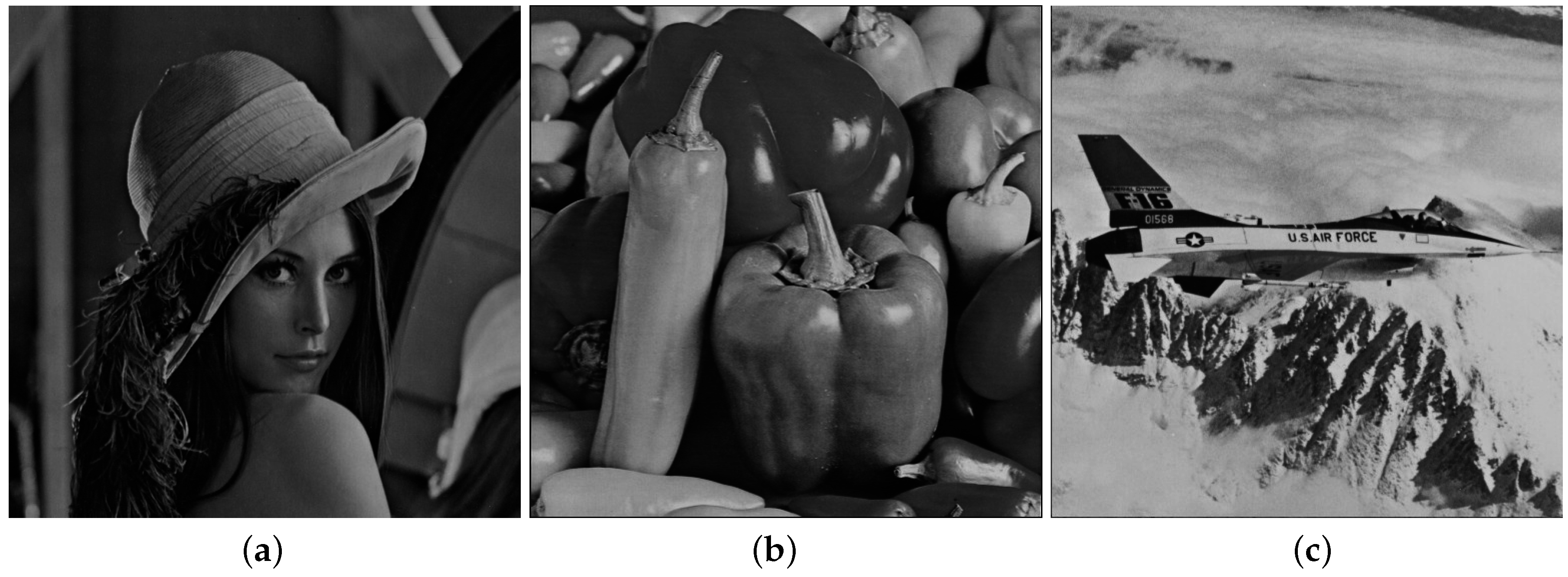
Figure 4.
Error patterns of Zhang’s system [4], Hong’s system [5], and the proposed scheme in the Lena image for s=8. (a) in (11) and (12); (b) in (13) and (14); (c) in (15) and (16); (d) in (15) and (16) + RS(15,11) code.

Figure 5.
Example of error recovery by using RS codes in the Lena image. (a) Error pattern in Figure 4c; (b) Analysis of the codeword for the error pattern.
Figure 5.
Example of error recovery by using RS codes in the Lena image. (a) Error pattern in Figure 4c; (b) Analysis of the codeword for the error pattern.
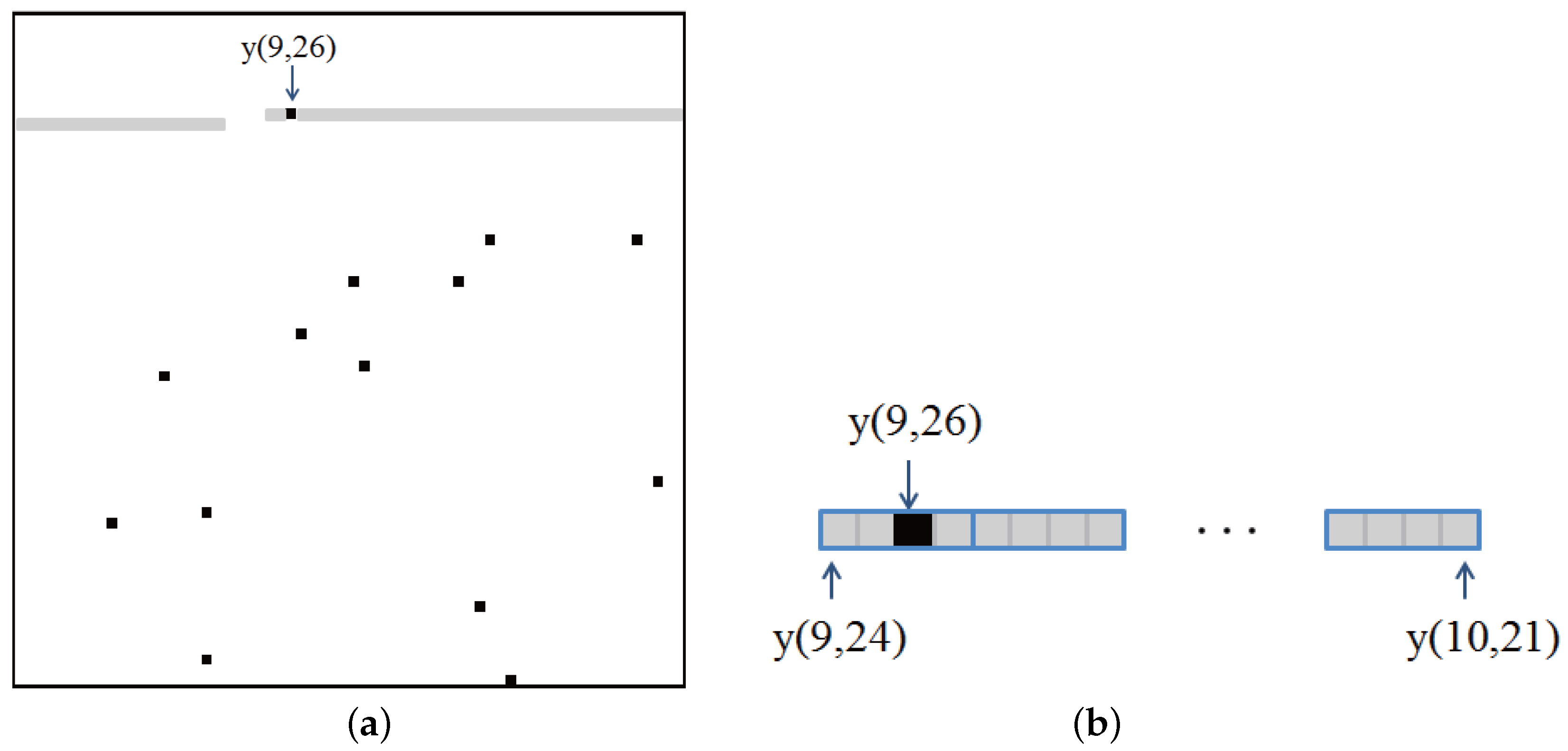
Figure 6.
BER performances of referenced and proposed fluctuation functions for the three images. (a) Lena; (b) Peppers; (c) Jet.
Figure 6.
BER performances of referenced and proposed fluctuation functions for the three images. (a) Lena; (b) Peppers; (c) Jet.
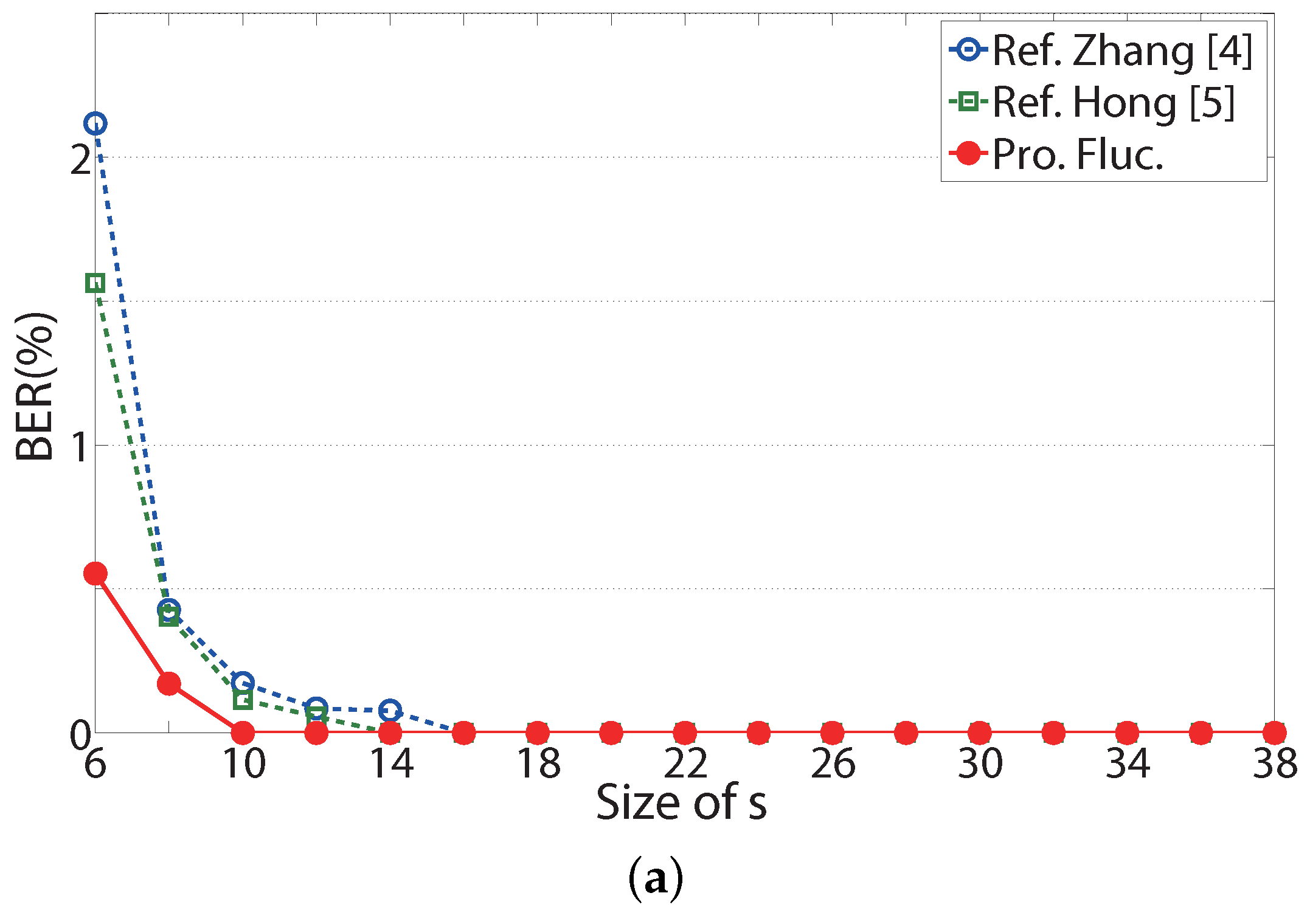

Figure 7.
BER performances of the proposed reversible data-hiding (RDH) systems with Reed–Solomon (RS) codes for the three images. (a) Lena; (b) Peppers; (c) Jet.
Figure 7.
BER performances of the proposed reversible data-hiding (RDH) systems with Reed–Solomon (RS) codes for the three images. (a) Lena; (b) Peppers; (c) Jet.
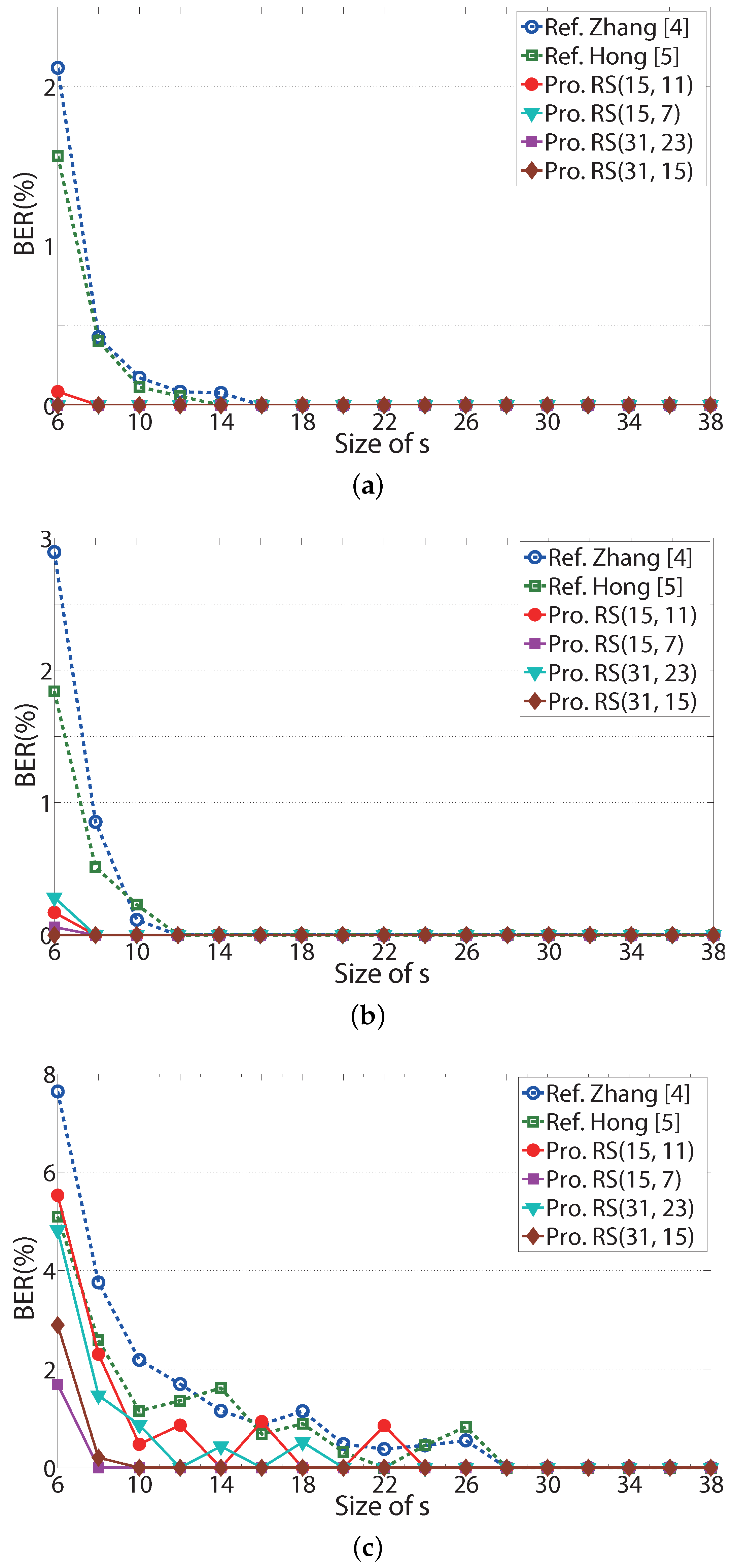
Figure 8.
PSNR performances of the proposed RDH systems with RS codes for the three images. (a) Lena; (b) Peppers; (c) Jet.
Figure 8.
PSNR performances of the proposed RDH systems with RS codes for the three images. (a) Lena; (b) Peppers; (c) Jet.


Table 1.
Minimum size of s for BER = 0 when the Lena image is used. G, gain.
| Rate | Min. s | No. Messages | Gain (%) | ||
|---|---|---|---|---|---|
| Ref. Zhang [4] | 1 | 16 | 1024 | G1 | G2 |
| Ref. Hong [5] | 1 | 14 | 1296 | ||
| Pro. RS(15, 11) | 0.73 | 8 | 3004 | 293.3 | 231.8 |
| Pro. RS(15, 7) | 0.47 | 6 | 3372 | 329.3 | 260.2 |
| Pro. RS(31, 23) | 0.74 | 6 | 5360 | 523.5 | 413.6 |
| Pro. RS(31, 15) | 0.48 | 6 | 3496 | 341.4 | 269.8 |
© 2017 by the author. Licensee MDPI, Basel, Switzerland. This article is an open access article distributed under the terms and conditions of the Creative Commons Attribution (CC BY) license (http://creativecommons.org/licenses/by/4.0/).
Share and Cite
MDPI and ACS Style
Kim, S. Reversible Data-Hiding Systems with Modified Fluctuation Functions and Reed-Solomon Codes for Encrypted Image Recovery. Symmetry 2017, 9, 61. https://doi.org/10.3390/sym9050061
AMA Style
Kim S. Reversible Data-Hiding Systems with Modified Fluctuation Functions and Reed-Solomon Codes for Encrypted Image Recovery. Symmetry. 2017; 9(5):61. https://doi.org/10.3390/sym9050061
Chicago/Turabian StyleKim, Sunghwan. 2017. "Reversible Data-Hiding Systems with Modified Fluctuation Functions and Reed-Solomon Codes for Encrypted Image Recovery" Symmetry 9, no. 5: 61. https://doi.org/10.3390/sym9050061
Note that from the first issue of 2016, this journal uses article numbers instead of page numbers. See further details here.