Article

Planning of Knotting Based on Manipulation Skills with Consideration of Robot Mechanism/Motion and Its Realization by a Robot Hand System

1
Graduate School of Information Science and Technology, The University of Tokyo, Tokyo 113-8656, Japan
2
Department of Mechanical Engineering, Chiba University, Chiba 263-8522, Japan
*
Author to whom correspondence should be addressed.
These authors contributed equally to this work.
Symmetry 2017, 9(9), 194; https://doi.org/10.3390/sym9090194
Submission received: 25 August 2017 / Revised: 4 September 2017 / Accepted: 12 September 2017 / Published: 15 September 2017
(This article belongs to the Special Issue Knot Theory and Its Applications)

Abstract

:
This paper demonstrates the relationship between the production process of a knot and manipulation skills. First, we define the description (rope intersections, grasp type and fixation positions) of a knot. Second, we clarify the characteristics of the manipulation skills from the viewpoint of the knot description. Next, in order to obtain the production process of the knot, we propose an analysis method based on the structure of the knot and the characteristics of the manipulation skills. Using the proposed analysis method, we analyzed eight kinds of knots, formed with a single rope, two ropes or a single rope and an object. Finally, in order to validate the production process obtained by the proposed analysis method, we show experimental results of an overhand knot and a half hitch produced by using a robot hand system.

1. Introduction

Manipulation of flexible linear objects is an important problem in the field of robotics, and the number of studies addressing this problem has been increasing recently. The authors have also developed new methods for the skills required by a robot hand in a knotting task and achieved a so-called overhand knot with a high-speed robot system [1].
However, it has not been demonstrated that the skills proposed in our previous work can produce many different types of knots. Therefore, in this paper, we examine this problem based on an original knotting algorithm. The goal of this paper is to analyze the knotting process and to define the relationship between the knotting process and the individual skills that can be performed by a robot hand.
In this paper, a “task” (knotting) is defined as one manipulation carried out by a robot, and “skill” (manipulation skill) is defined as a minimum required element to achieve the task and a meaningful element that changes the rope state. Therefore, one task is achieved by the combination of a certain number of skills. In order to further develop the manipulation theory and its implementation, it is important not only to achieve many tasks, but also to integrate the skills that are needed for task realization, as shown in Figure 1. This paper is summarized as follows:
  • We define a problem setting for knotting manipulation (Section 2).
  • We extract several basic manipulation skills for knotting (Section 3.1).
  • We propose a knot description based on knot theory (Section 3.2), and we identify the characteristics of manipulation skills using the knot description (Section 3.3).
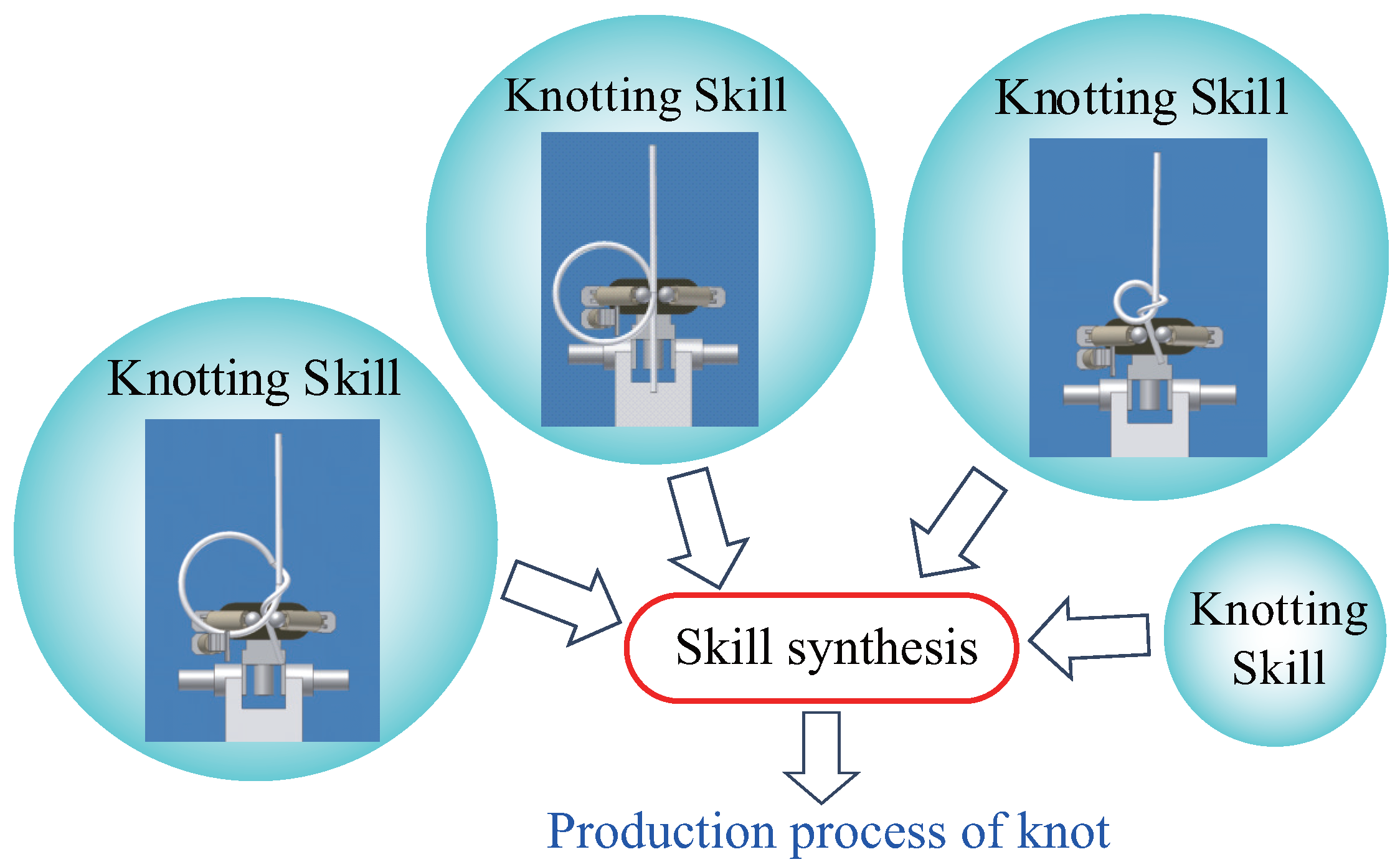
  • We also suggest a method for obtaining a knotting procedure in which several knots can be achieved by synthesizing these skills (Section 4.1).
  • We analyzed several types of knots using the proposed method (Section 4.2, Section 4.3 and Section 4.4).
  • We realized two kinds of knots (overhand knot and half hitch) using a robot hand system (Section 5).
  • We finally conclude this article and discuss future work (Section 6).

1.1. Related Work

Several researchers have focused on the manipulation of linear flexible objects. For example, Inaba et al. proposed a method of knotting a rope with a manipulator [2]. Matsuno et al. used an imaging system to recognize the shape of a rope and demonstrated knotting using dual manipulators [3]. Saha et al. suggested a topological motion planner for manipulating flexible linear objects [4]. Morita et al. proposed a knot planning technique using a system called Knot Planning from Observation (KPO) [5]. Wakamatsu et al. formulated a description of knots and a process of knot manipulation [6]. In their study, they considered the geometry of the knot and proposed a knotting process. In other researches, a knotting task that takes into consideration the robot motion and a rope model was executed by a robot arm [7,8], and knotting using a special mechanism with fixation of the rope and the geometrical relation of the knot was studied [9,10].
However, the main topic in the above studies was the analysis of the knot geometry. In experiments conducted by those authors, a manipulator was typically controlled along a trajectory based on the knot geometry. However, the characteristics of the manipulator and end-effector were not considered. As a result, there was considerable redundancy in the motions of the manipulator. In order to achieve knotting at high speed, it is necessary to develop the skills required by the manipulator and end-effector for the knotting task. The aim of our research is to identify the manipulation skills required by a general robot arm and robot hand to achieve a knotting task, as shown in Figure 2.

1.2. Contribution

In order to achieve knotting manipulation for any reference knot, a knotting procedure is strongly required, as shown in Figure 1 [11,12,13]. In this article, we propose an entirely new method for obtaining the knotting procedure based on manipulation skills for knotting by a robot system, as shown in Figure 2. By using the proposed method, we can perform various knotting manipulations with the robot. In particular, the originality of our proposed method is that we consider not only the knot structure, but also the robot mechanism and motion in the knotting procedure. Moreover, we describe several knotting procedures using the proposed method, and we show actual knotting manipulations of two kinds of knots produced by a high-speed robot system.

2. Problem Setting

The knots to be handled in this research include:
  • a knot formed with a single rope,
  • a knot formed with two ropes and
  • a knot formed with a single rope and an object.
Although a knot has a three-dimensional shape, we consider the projected shape of the knot in a two-dimensional plane. This implies that the conventional knot description based on the intersection description in the knot theory can be introduced [6,14], and the actual knotting performed by the robot is performed in a two-dimensional plane, such as on a tabletop. This plane is called the “knot production plane” in this paper.
Under this setting, the following conditions for high-speed knotting manipulation are assumed:
  • As shown in Figure 3, a rope is manipulated by an end-effector with two fingers and a robot arm, where the two fingers perform grasping and manipulation of the rope.
  • The knot shape during manipulation can be held at multiple fixation points.
  • The knot is produced on the knot production plane, and the robot can approach the knot production plane from only one direction, such as from above.
Knotting manipulation is performed by the following procedure:
  • Given a reference knot,
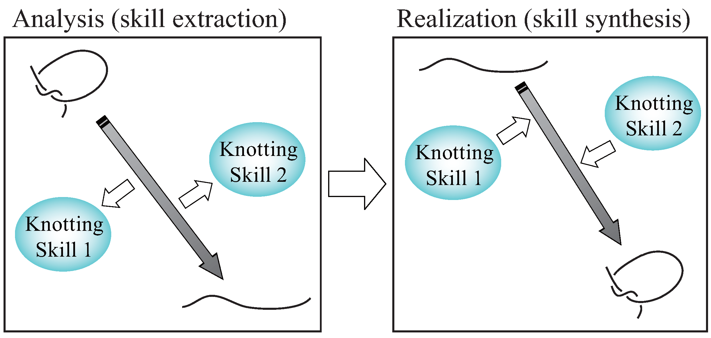
  • Describe the knot and analyze the knot while unraveling it,
  • Develop a plan to tie the knot based on the analysis result and
  • Produce the knot with a robot system.

3. Manipulation Skills and Knot Description

First, we extract manipulation skills for planning the knot manipulation and realizing the knot with a robot. Next, we define the knot description based on knot theory, and we describe the characteristics of the manipulation skills.

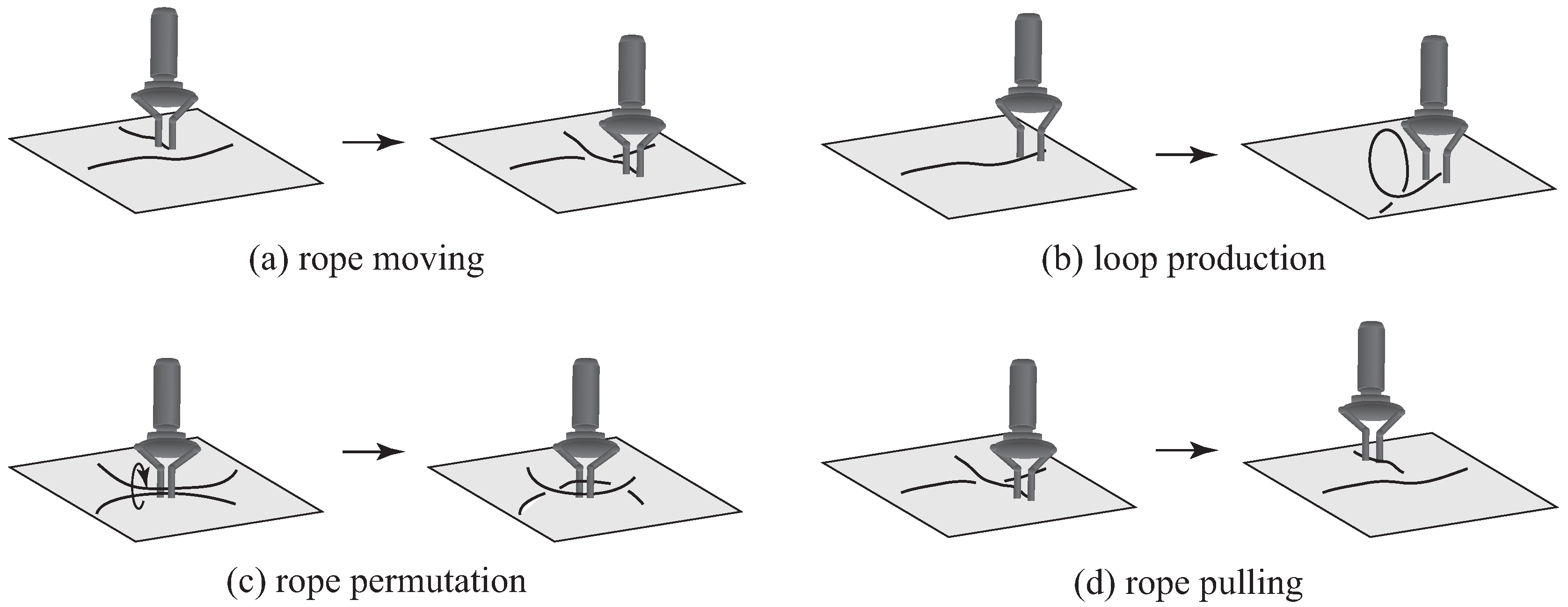
3.1. Extraction of Manipulation Skills

Extracting the necessary and appropriate manipulation skills is extremely important for producing the knot with the robot. We first analyzed how a human subject tied a knot (overhand knot, shown in Figure 4) to extract the required manipulation skills. Figure 4a–c shows loop production using hand motion. Figure 4d,e shows rope permutation using finger motion. Figure 4f–h shows rope pulling using hand motion. From these results, we can extract three manipulation skills, namely “loop production”, “rope permutation” and “rope pulling”. In addition to these three manipulation skills, we add one more manipulation skill, “rope moving”, in order to handle the end of the rope. Therefore, the manipulation skills required for knotting are summarized as follows, and these manipulation skills are illustrated in Figure 5: (1) loop production (Figure 5b), (2) rope permutation (Figure 5c), (3) rope pulling (Figure 5d) and (4) rope moving (Figure 5a).

3.2. Knot Description

This section defines descriptions of intersections, grasp types of intersections, and fixation locations of the rope.

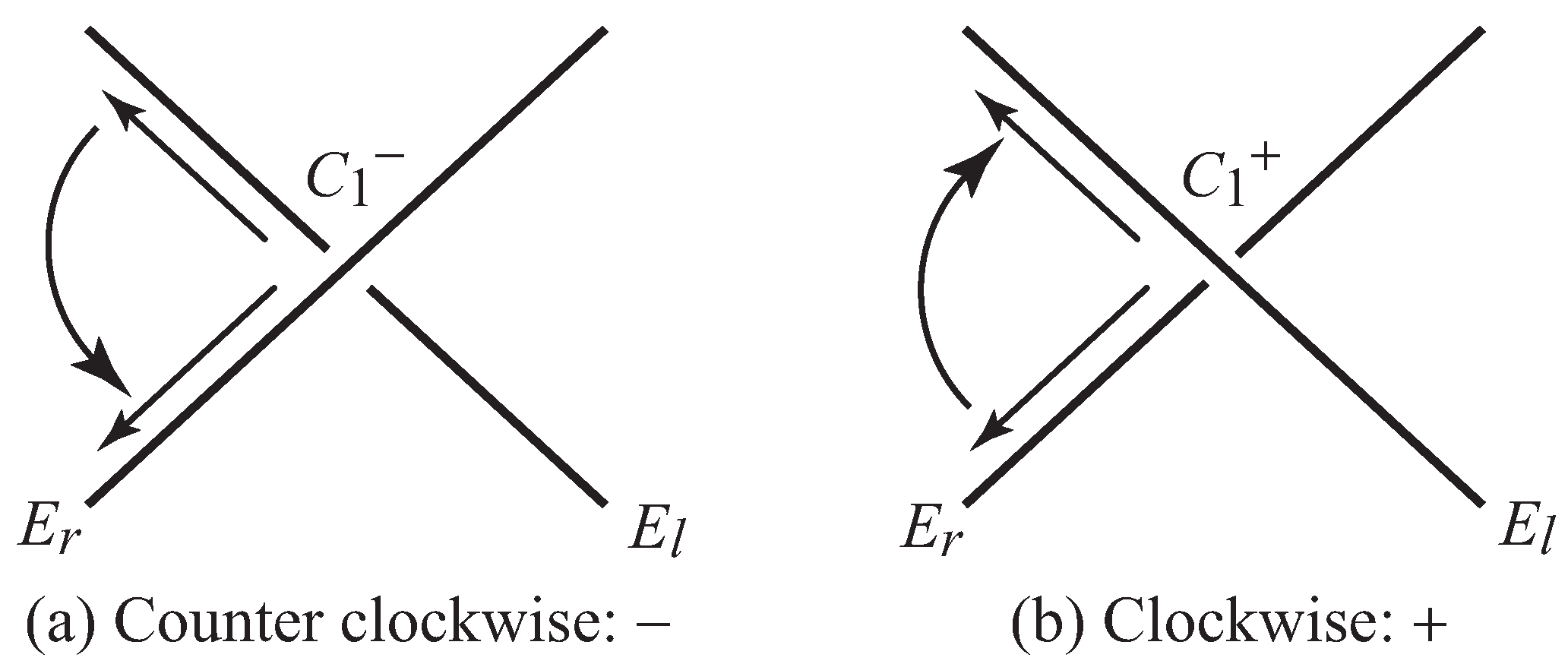
3.2.1. Description of Intersections

Figure 6 shows signs assigned to intersections. In the case of a knot in a single rope, the two ends of the rope are represented by E l and E r ; and in the case of knots in two ropes and knots in a single rope and an object, the ends of the ropes and the object are represented by l 1 , l 2 , r 1 and r 2 . Descriptions of the intersections C i { + , } are assigned for all intersections from E l E r or from l 1 l 2 , where the subscript i is an intersection number. The sign “ + , ” shows the intersection sign. The sign “−” is counter clockwise (Figure 6a), and the sign “+” is clockwise (Figure 6b).

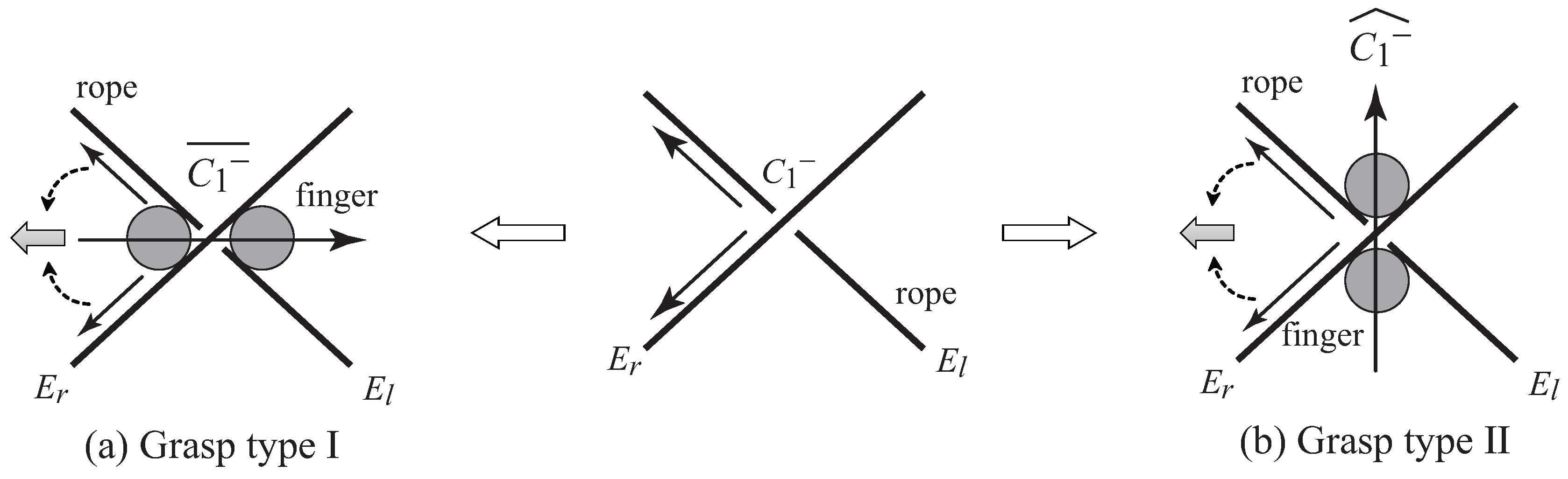
3.2.2. Description of Grasp Types of Intersections

In addition to the description of intersections, we introduce a new description of the grasp types of intersections. In the case where an intersection is grasped by two fingers, the relationship between the grasp type and the manipulation skill can be easily identified by distinguishing between grasp types. Thus, we define the relationship between the grasp type and the description as shown in Figure 7. Figure 7 shows a cross-sectional view of the grasp types of intersections, where the grasp types are divided into the two types shown in Figure 7a,b. We consider only the grasp state of the intersection by two fingers, and the angle between the two sections of the rope is not considered.
First, the two directions of the rope at “outlets” of the intersection are summed, which is the gray arrow shown in Figure 7. Second, the line that connects the two fingers grasping the intersection is considered. Finally, the relationship between the summed rope direction and this connecting line is examined. If the relationship is parallel, the description of the intersection shown in Figure 7a is defined as C i { + , } ¯ . If the relationship is orthogonal, the description of the intersection shown in Figure 7b is also defined as C i { + , } ^ . This description method is used in loop production, in particular.

3.2.3. Description of Fixation Locations of Rope

Let us consider a case where the intersection on the loop is grasped by the robot and the intersection is produced by permutation. However, the whole loop is rotated by permutating the intersection in this case, as shown in Figure 8. As a result, the geometrical structure (production of intersection) cannot be changed by this operation. Moreover, the geometrical structure may be unexpectedly changed by this operation. In order to solve these problems and perform operations appropriately, fixation of the rope is required. Therefore, the necessary fixation locations of rope are considered as follows: (1) end point of rope, (2) rope intersection and (3) one point on the loop.
Fixation at the edge point of the rope is needed so as to fix the initial position of the edge, and fixation of the rope intersection is needed so as to maintain the geometrical relation of the knot. Fixation of one point on the loop is also needed so as not to rotate the whole loop. The descriptions of these fixation locations are indicated by the subscripts f, m and p. In the case of the fixation of the edge point of the rope, the description is E l , f ( l 1 , f ). In the case of the fixation of the rope intersection and one point on the loop, the descriptions are defined as C i , m { + , } and C i , p { + , } , respectively. Concrete descriptions together with manipulation characteristics will be explained in the next section.
Actual methods for fixing the rope include fixing the rope by using another finger or applying tension to the rope.

3.3. Characteristics of Manipulation Skills
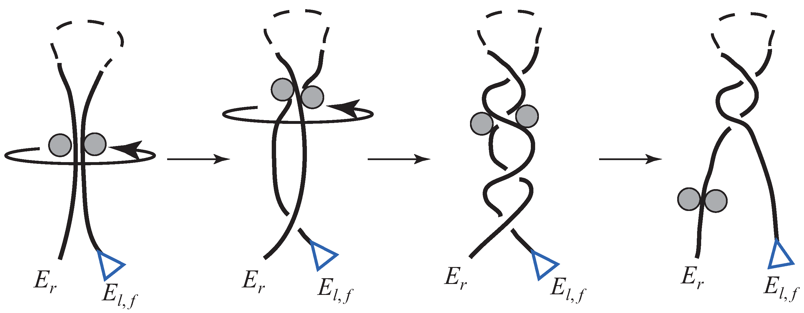
This section discusses manipulation skills in order to understand their characteristics based on the description of the knot.

3.3.1. Rope Moving

Rope moving is defined as free motion of the end of the rope on the knot production plane. Rope moving is used to cross the two sections of the rope (Figure 9a) or to set one section close to another (Figure 9b). The dotted line in Figure 9 indicates a simplified structure of the knot for this part.
Starting from E l , we walk along the rope writing down each crossing that we meet together with its sign until we reach E r . During this process, each crossing is met twice. For example, in the case where the two sections are intersected, as shown in Figure 9a, one intersection is created, and the description of the intersection can be written as,
E l , f E r E l , f C 1 { + , } C 1 { + , } E r ( single rope )
l 1 , f l 2 l 1 , f C 1 { + , } l 2 r 1 , f r 2 , f r 1 , f C 1 { + , } r 2 , f ( two ropes ) .
In the case where one section of the rope approaches another, as shown in Figure 9b, an intersection is not made.
In rope moving of a single rope in the case where there are intersections already, fixation at the intersection and the loop is needed to maintain the geometrical relation of the knot, as shown by the blue triangle in Figure 10a. The two fixation locations are indicated by subscripts m and p as follows:
E l , f C i , m p { + , } C i , m p { + , } E r .
In the same way, fixation for rope moving of two ropes is also needed to maintain the geometrical relation of the knot, as shown by the blue triangle in Figure 10b. The fixation is indicated by subscript m as follows:
l 1 , f C i , m { + , } l 2 r 1 , f C i , m { + , } r 2 , f .

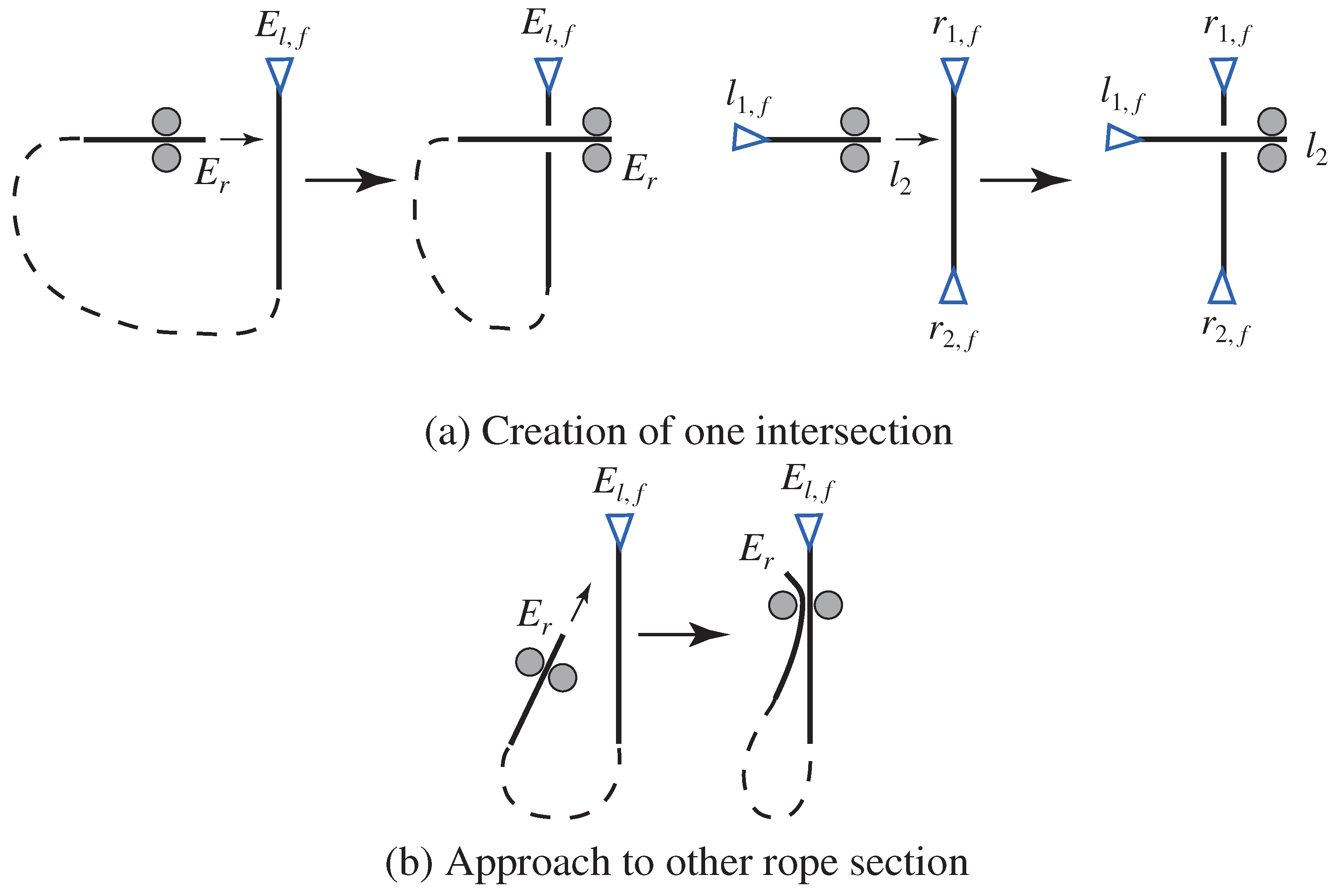
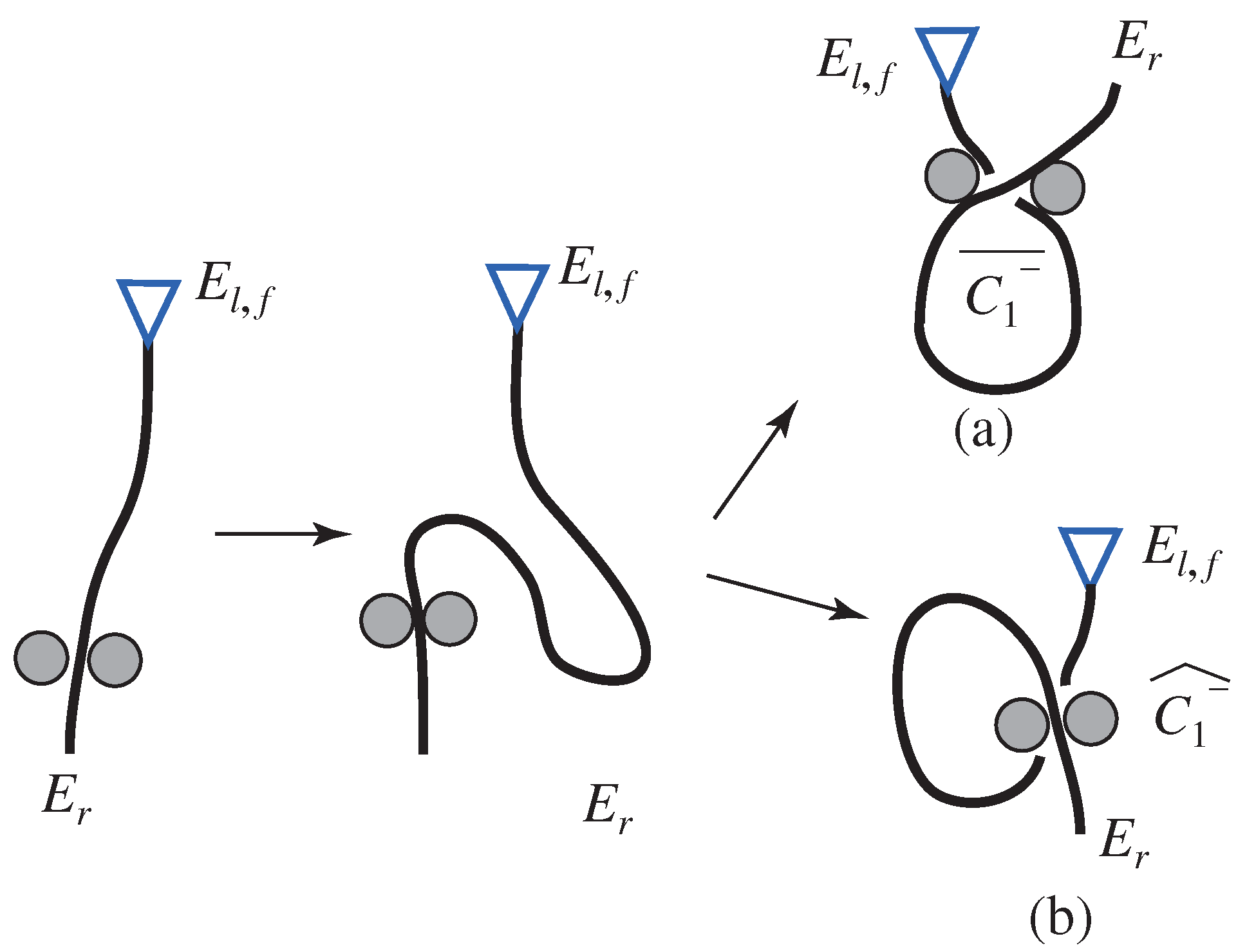
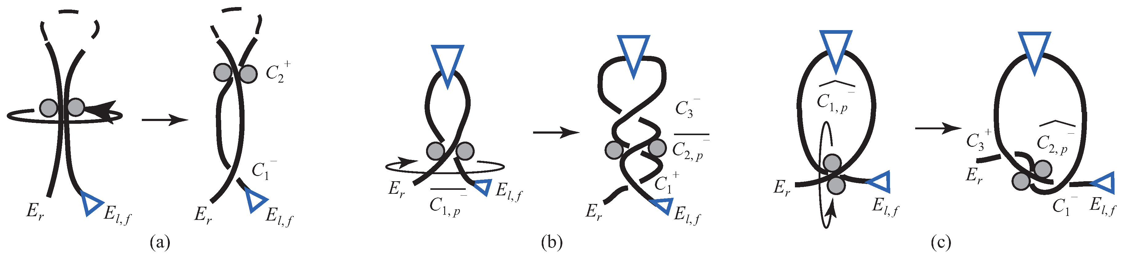
3.3.2. Loop Production

Loop production is a special example of rope moving and is an operation that makes one intersection in a single rope, as shown in Figure 11. The description of the intersection can be written as (see Figure 11a),
E l , f E r E l C 1 { + , } ¯ C 1 { + , } ¯ E r
or (see Figure 11b)
E l , f E r E l C 1 { + , } ^ C 1 { + , } ^ E r .
The cross sign of the intersection depends on the positioning of the loop, that is which is the overpassing arc and which the underpassing. The grasp type also depends on the loop production method.

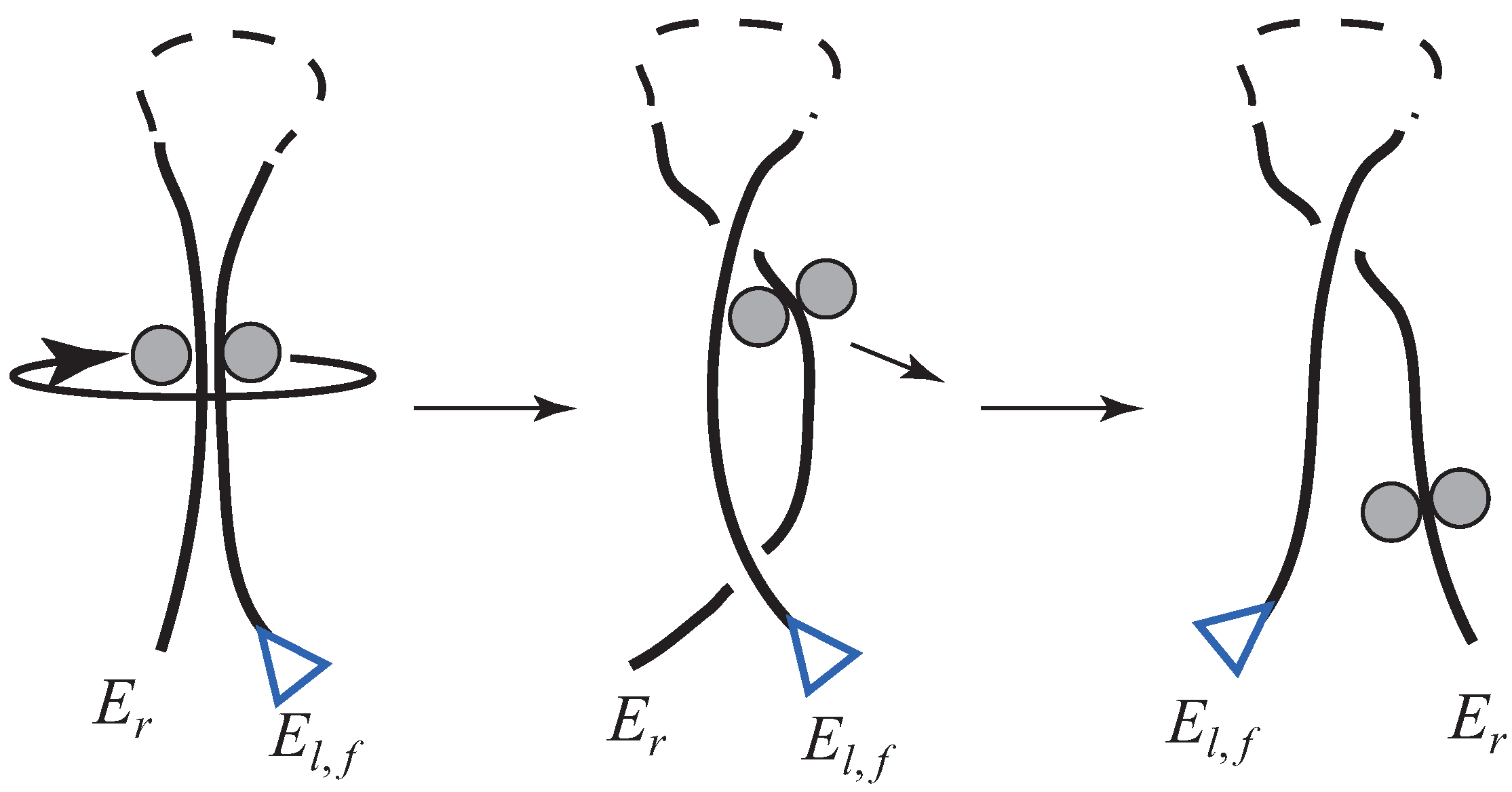
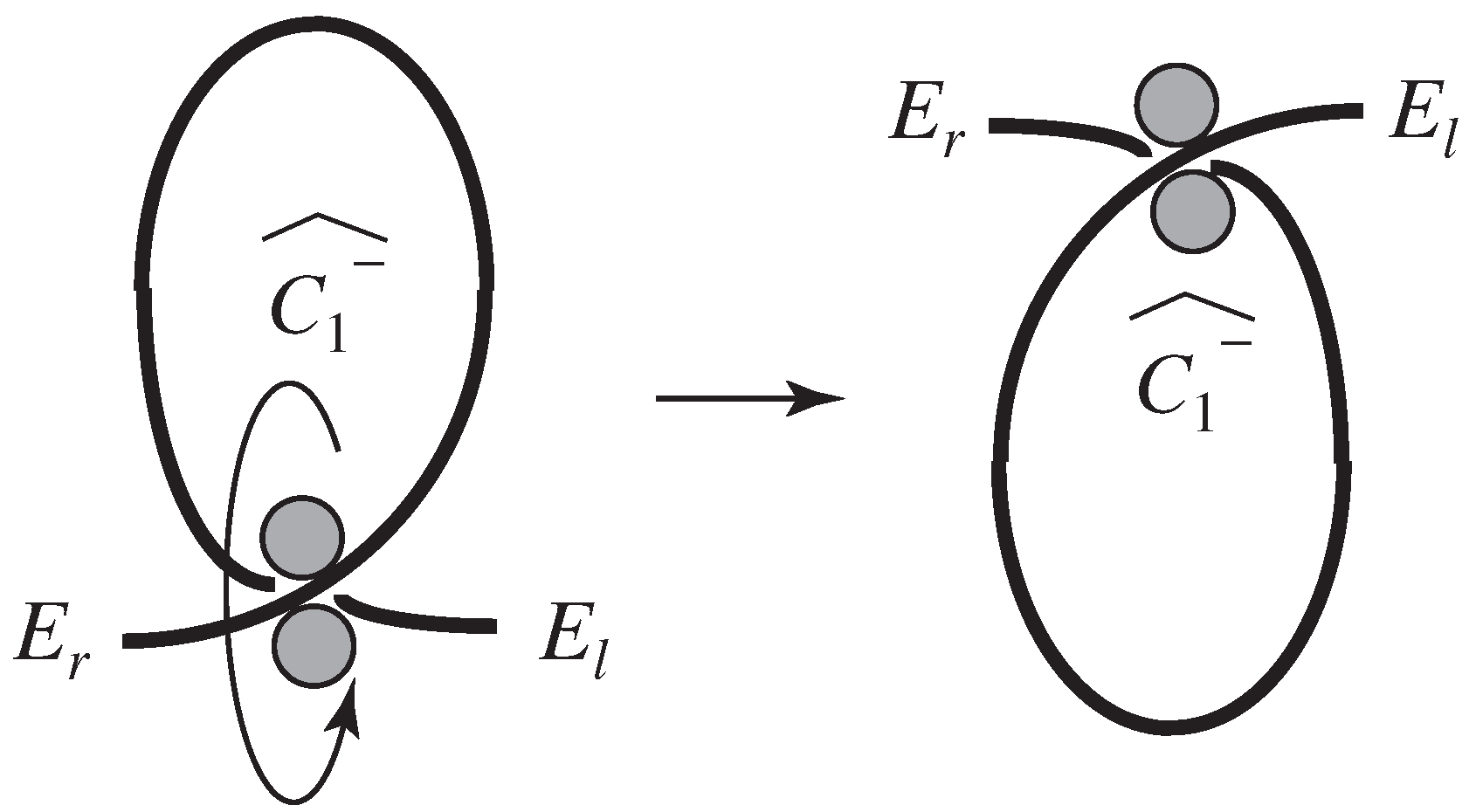
3.3.3. Rope Permutation
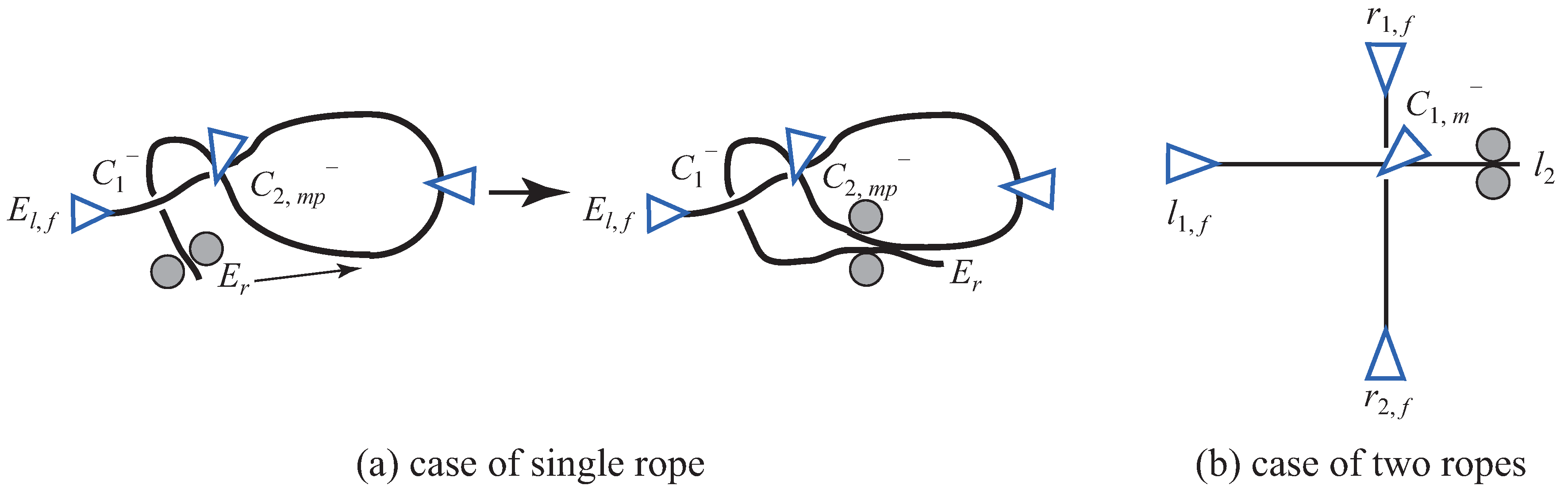
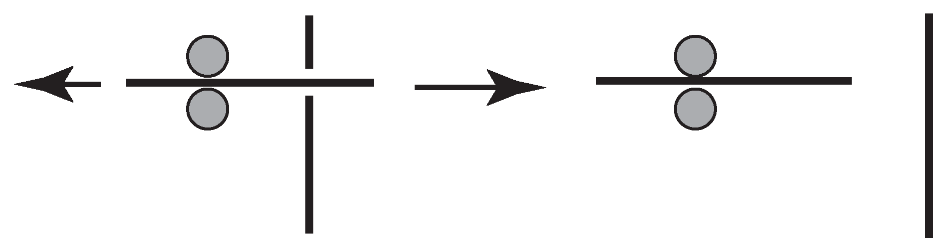
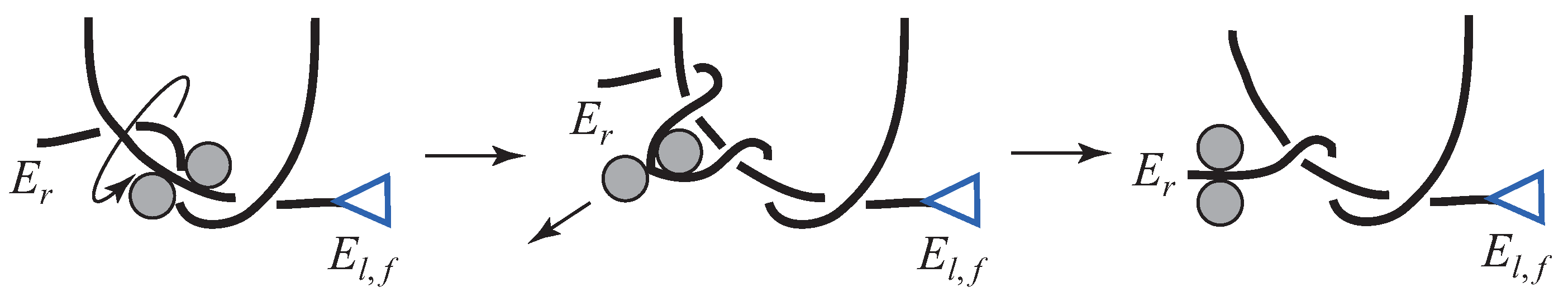
Rope permutation is divided into three types as shown in Figure 12a–c. Figure 12a represents the rope permutation in the case where the robot grasps two parallel sections that do not possess intersections, and the description of the intersection is as follows:
E l , f E r E l , f C 1 { + , } C 2 { , + } C 2 { , + } C 1 { + , } E r .
Figure 12b shows the state after loop production and corresponds to Figure 11a. Here, fixation is needed so as not to rotate the whole loop. In the description, the subscript p is added to indicate this fixation. In this operation, two intersections are created, and the description is expressed as,
E l , f C 1 , p { + , } ¯ C 1 , p { + , } ¯ E r E l , f C 1 { , + } C 2 , p { + , } ¯ C 3 { + , } C 3 { + , } C 2 , p { + , } ¯ C 1 { , + } E r .
In addition, Figure 12c also shows the state after loop production and corresponds to Figure 11b. In this case, fixation is also required. The description of the intersection is:
E l , f C 1 , p { + , } ^ C 1 , p { + , } ^ E r E l , f C 1 { + , } C 2 , p { + , } ^ C 3 { , + } C 1 { + , } C 2 , p { + , } ^ C 3 { , + } E r .

3.3.4. Rope Pulling

Rope pulling is an operation that basically removes the intersection, as shown in Figure 13. This skill is effective when used together with rope permutation.

Rope Permutation and Rope Pulling

By utilizing rope permutation and rope pulling, three skills can be executed, such as the production of continuous multiple intersections (Figure 14), changing the cross sign of an intersection (Figure 15) and crossing one section under the rope on the knot production plane (Figure 16).
In the case where the number of intersections is increased (Figure 14), the description becomes:
E l , f E r E l , f C 1 { + , } C 2 { , + } C 2 { , + } C 1 { + , } E r ( single rope )
l 1 , f l 2 l 1 , f C 1 { + , } C 2 { , + } l 2 r 1 , f r 2 , f r 1 , f C 1 { + , } C 2 { , + } r 2 , f ( two ropes ) .
Moreover, in the case where the sign at one intersection is changed (Figure 15), the description becomes:
E l , f C 1 { + , } C i { + , } C 1 { + , } E r
E l , f C 1 { + , } C i { , + } C 1 { + , } E r .
In addition, in the case where the rope makes a cross under the rope (Figure 16), the description becomes:
E l , f E r E l , f C 1 { + , } C 1 { + , } E r .

4. Knot Analysis

Here, we propose an analysis method for knot planning, and we analyze various kinds of knots using the proposed method. In particular, we deal with the following types of knots:
  • a knot formed with a single rope,
  • a knot formed with two ropes, and
  • a knot formed with a single rope and an object.

4.1. Analysis Method

In this section, we describe the analysis method for obtaining the procedure for knotting manipulation by a robot system. To achieve this, we introduce an assumption and summarize the rules for the manipulation skills. We also propose an analysis method including concrete algorithm flows for unraveling and knotting.

4.1.1. Constraint Condition for Knotting Manipulation
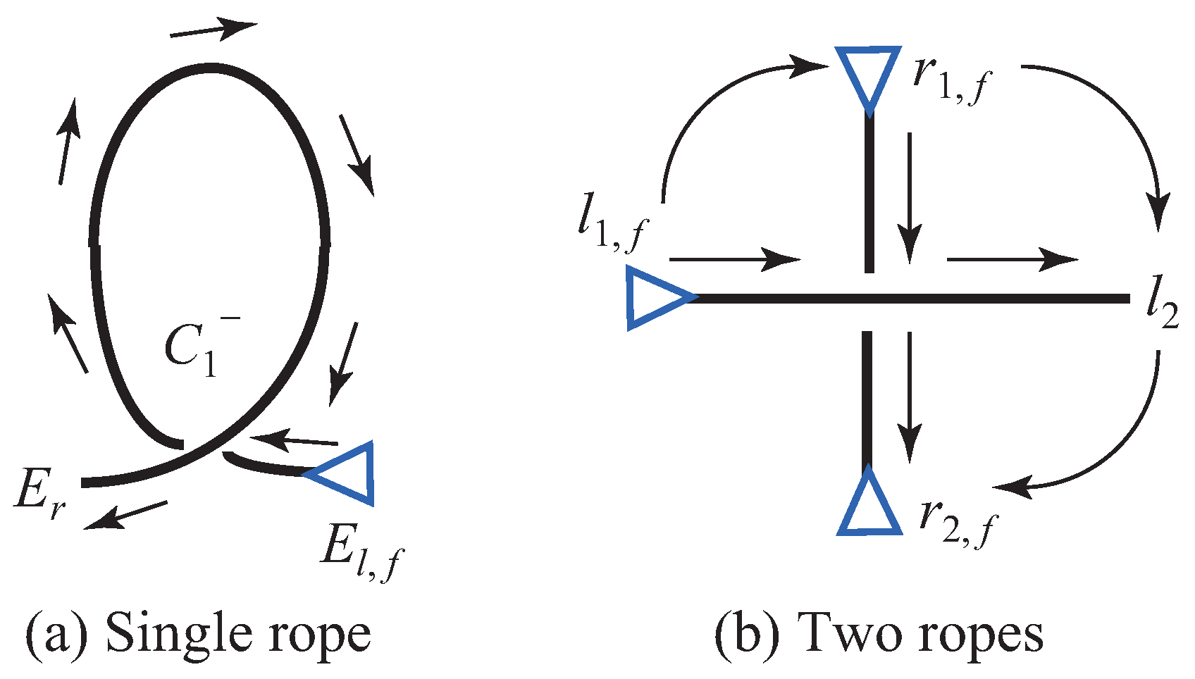
First, we define a constraint condition for the analysis. In the knotting manipulation, a production process for the first intersection is not specified, and thus, an intersection with a + or − cross sign is produced. In order to specify that the first intersection has the cross sign −, we introduce the following condition. Here, the reason that the first intersection with the sign − is chosen is that it is convenient, and the first operation is specified as overpassing in the knot production plane.
Case of the knot in single rope (see Figure 17a):
  • E l is fixed ( E l , f ), and E r is freely moved by the robot.
  • The first intersection is produced so as to change the rope direction clockwise from E l , f to E r .
  • E r passes over the rest of the string.
Case of the knot with two ropes (see Figure 17b):
  • l 1 , r 1 and r 2 are fixed ( l 1 , f , r 1 , f , r 2 , f ), and l 2 is freely moved by the robot.
  • The first intersection is produced so as to assign the direction ( l 1 , f r 1 , f l 2 r 2 , f ) clockwise.
  • l 2 passes over the rest of the string.
By introducing this assumption, the first intersection is produced on the rope as shown in Figure 17.

4.1.2. Rules for Manipulation Skills

Here, we discuss rules for the manipulation skills based on the constraint condition described in the previous section.
The first intersection, which is created under the constraint condition, must be C 1 . According to this condition, we can summarize the manipulation skills as shown in Table 1. Thus, since we know, from the unraveling, the location and the cross sign of the next intersection to be created, we can identify the manipulation skill while following the unraveling sequence in reverse. In Table 1, the manipulation skills are represented as follows: rope moving (S), loop production (T), rope permutation (U) and rope pulling (V). Furthermore, UV means that rope permutation and rope pulling are performed in sequence. These symbols are used in the analysis results presented in Section 4.2, Section 4.3 and Section 4.4.

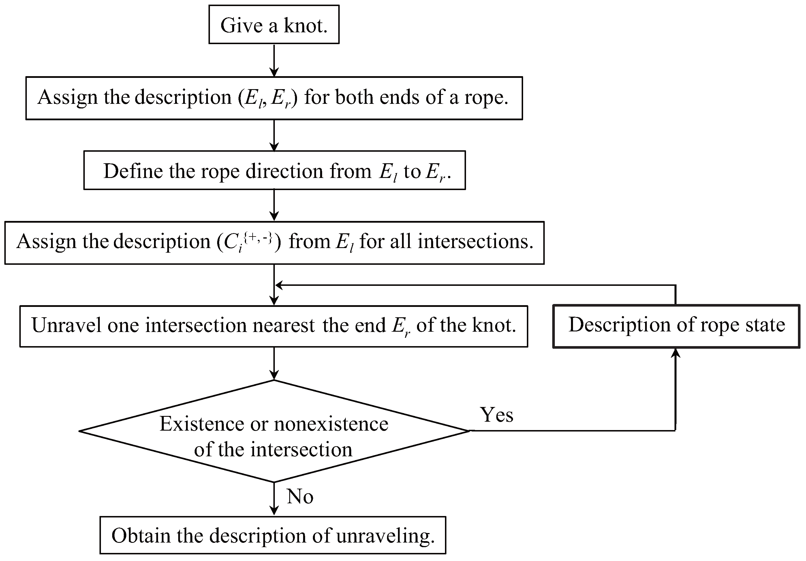
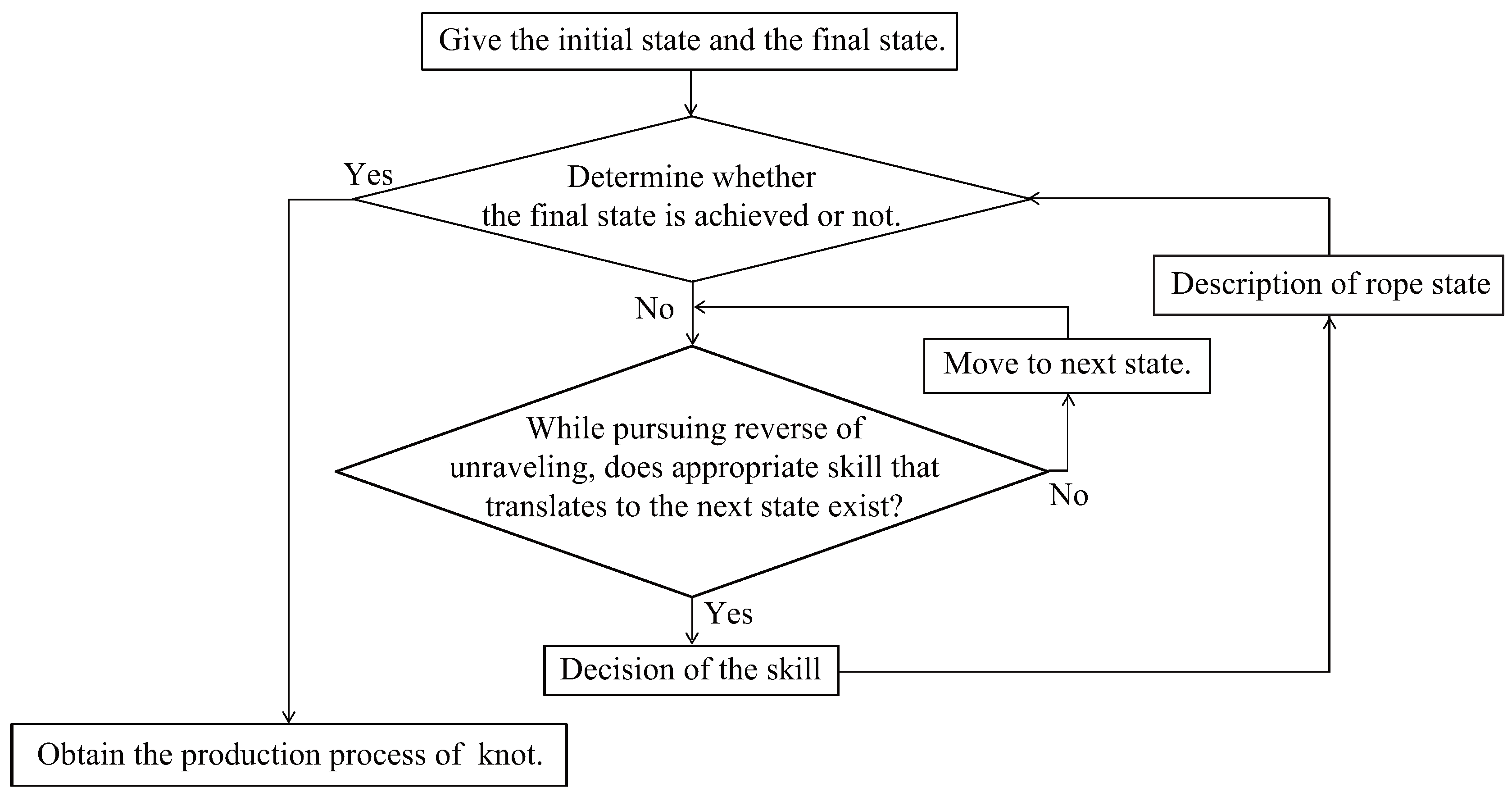
4.1.3. Overall Procedure

Here, we explain the overall procedure of the analysis method, and then, we describe the concrete algorithm flow in the method. The overall procedure is as follows:
  • Represent a knot based on the knot description explained in the previous section.
  • Unravel one intersection of the knot, starting from the intersection nearest the end of the rope.
  • Iterate Step 2 until all intersections disappear. As a result, a sequence of operations for removing the intersections is obtained.
  • Apply appropriate manipulation skills to the sequence, while following the sequence obtained in Step 3 in reverse.
With this process, the location and the sign of each intersection are identified. As a result, it can be determined how to generate the intersection. This analysis can be applied not only to a knot formed with one rope, but also to a knot formed with one rope and one object and a knot formed with two ropes. Although the knot production process obtained by the proposed method may not be optimal, this method can always provide one solution for the knot production process.
The concrete flow for knot analysis is as shown in Figure 18 (unraveling) and Figure 19 (knotting).

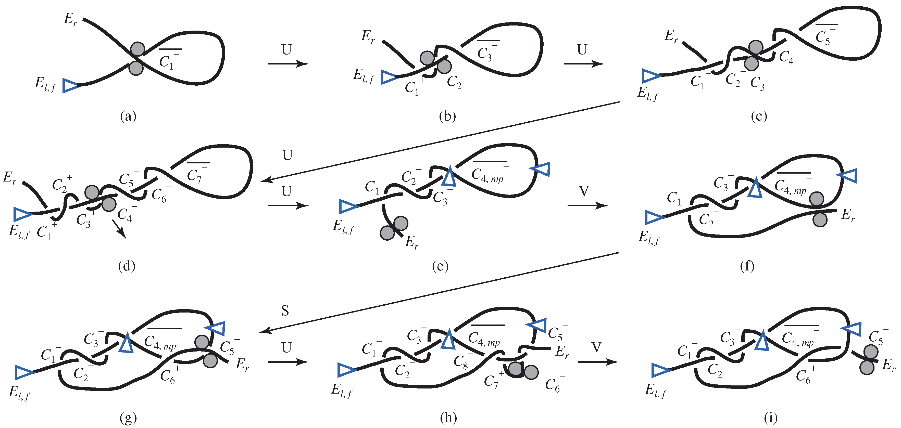
4.2. Knots with a Single Rope

Here, we consider the description and production method of a knot with a single rope. Pick one endpoint as the beginning of the rope, and denote it by E l . The end of the rope is represented by E r . As concrete examples of knots, we deal with: (1) an overhand knot, (2) a figure-eight knot and (3) a stevedore knot.
Due to space limitations, we show all analysis results only for the overhand knot, and we describe only the procedure of knotting manipulation for the other two knots.

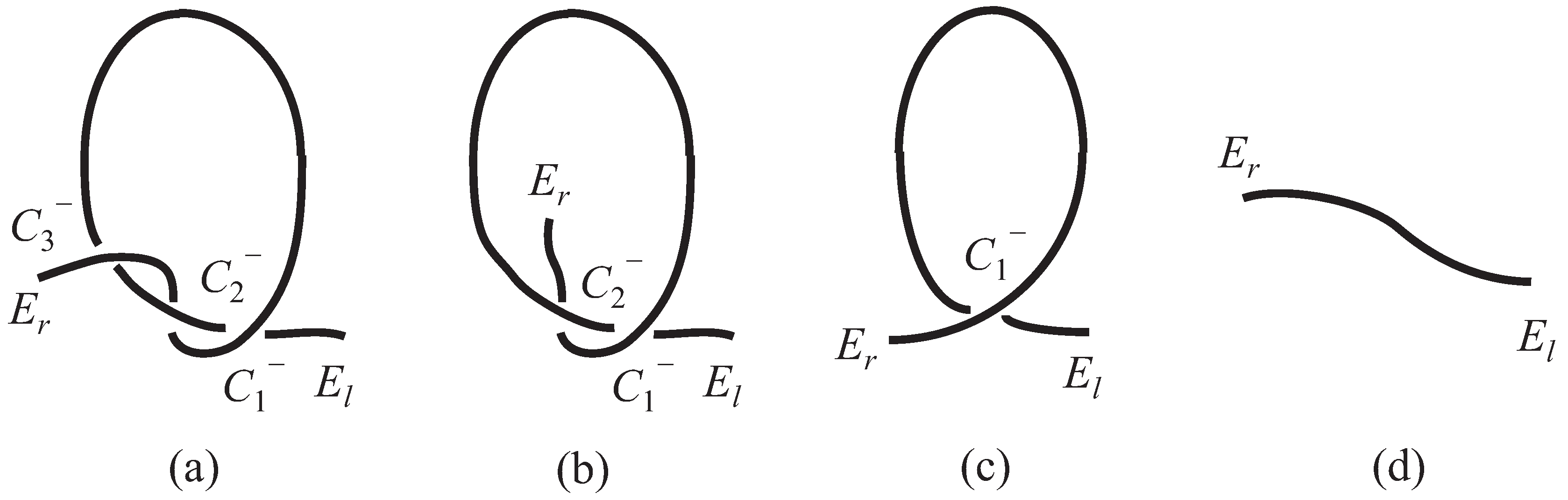
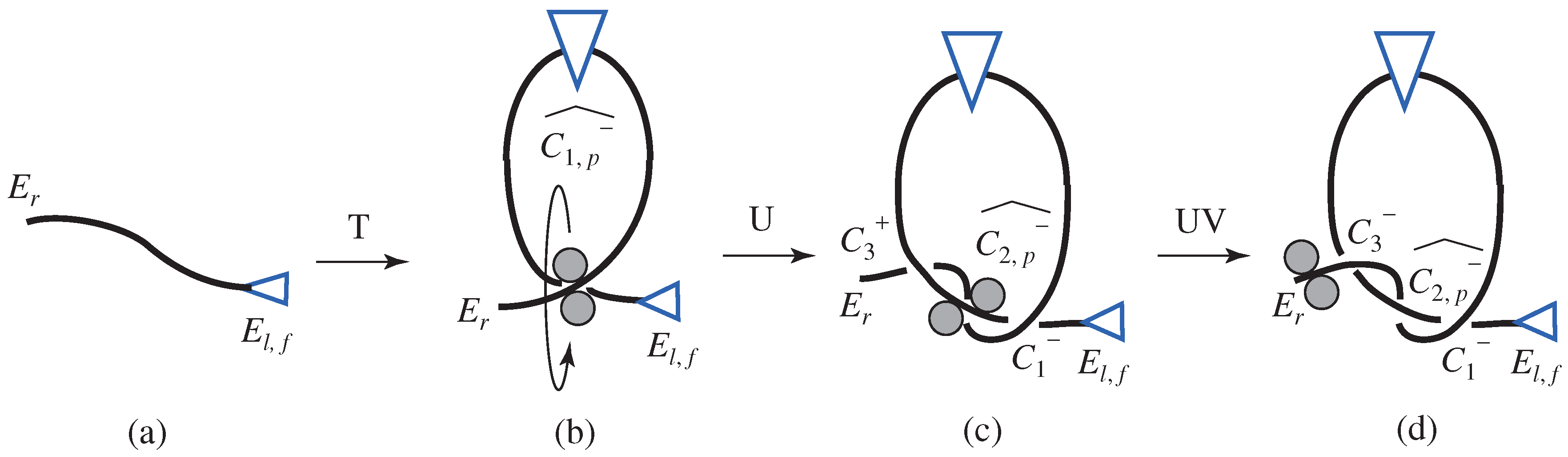
4.2.1. Overhand Knot

The first example is the “overhand knot”, which is the simplest and most typical knot.

Unraveling of Overhand Knot

By unraveling one intersection, starting from the intersection ( C 3 ) near the end ( E r ) of the rope, the analysis result can be obtained as follows (Figure 20a–d):
E l C 1 C 2 C 3 C 1 C 2 C 3 E r ( a )
E l C 1 C 2 C 1 C 2 E r ( b )
E l C 1 C 1 E r ( c )
E l E r ( d )
The production process of the overhand knot can be obtained by following this process in reverse while considering the description of the intersections.

Knotting of Overhand Knot

First, loop production is performed, and the intersection C 1 ^ is created (Figure 21b). Second, the intersection C 2 is produced. However, it is not effective to produce only the intersection C 2 . By checking the final type of knot, it is found that two intersections should be made after the intersection C 1 . In addition, the final intersection C 3 should pass under the rope. For these reasons, the state shown in Figure 21c can be produced only by performing rope permutation (Figure 12c). Finally, using rope permutation and rope pulling, the overhand knot is achieved, as shown in Figure 21d. The description of the intersections for the overhand knot production process is as follows:
E l , f E r ( a )
E l , f C 1 , p ^ C 1 , p ^ E r ( b )
E l , f C 1 C 2 , p ^ C 3 + C 1 C 2 , p ^ C 3 + E r ( c )
E l , f C 1 C 2 , p ^ C 3 C 1 C 2 , p ^ C 3 E r ( d )

4.2.2. Figure-Eight Knot

First, loop production is performed, and the intersection C 1 ¯ is created as shown in Figure 22b. Second, according to the rules of the manipulation skills, rope permutation and rope pulling (Figure 16) are carried out to create an even-numbered intersection with sign − (second intersection), and then, the intersection C 1 is produced (Figure 22c). Next, the state shown in Figure 22d can be obtained by rope moving, in which the fixation of the rope is needed, and the description of this fixation is added. Finally, the intersections C 3 + and C 4 + are created by performing rope permutation and rope pulling twice, thus completing the figure-eight knot, as shown in Figure 22e,g.
E l , f E r ( a )
E l , f C 1 ¯ C 1 ¯ E r ( b )
E l , f C 1 C 2 , m p ¯ C 2 , m p ¯ C 1 E r ( c )
E l , f C 1 C 2 , m p ¯ C 3 C 4 + C 2 , m p ¯ C 1 C 4 + C 3 E r ( e )
E l , f C 1 C 2 , m p ¯ C 3 + C 4 + C 2 , m p ¯ C 1 C 4 + C 3 + E r ( g )

4.2.3. Stevedore’s Knot

First, an intersection C 1 ¯ is made by loop production (Figure 23a). Then, three intersections ( C 1 , C 2 , C 3 ) are created by performing rope permutation (Figure 12a) three times in sequence and performing rope pulling (Figure 23e) once. Next, the state shown in Figure 23f is obtained by rope moving, in which the fixation of the rope is needed, and the description of this fixation is added. Moreover, two intersections ( C 5 + , C 6 + ) are produced by performing rope permutation two times and rope pulling one time, thus completing the stevedore knot (Figure 23i).
E l , f E r
E l , f C 1 ¯ C 1 ¯ E r ( a )
E l , f C 1 C 2 C 3 C 4 , m p ¯ C 4 , m p ¯ C 3 C 2 C 1 E r ( e )
E l , f C 1 C 2 C 3 C 4 , m p ¯ C 5 C 6 + C 4 , m p ¯ C 3 C 2 C 1 C 6 + C 5 E r ( g )
E l , f C 1 C 2 C 3 C 4 , m p ¯ C 5 + C 6 + C 4 , m p ¯ C 3 C 2 C 1 C 6 + C 5 + E r ( i )

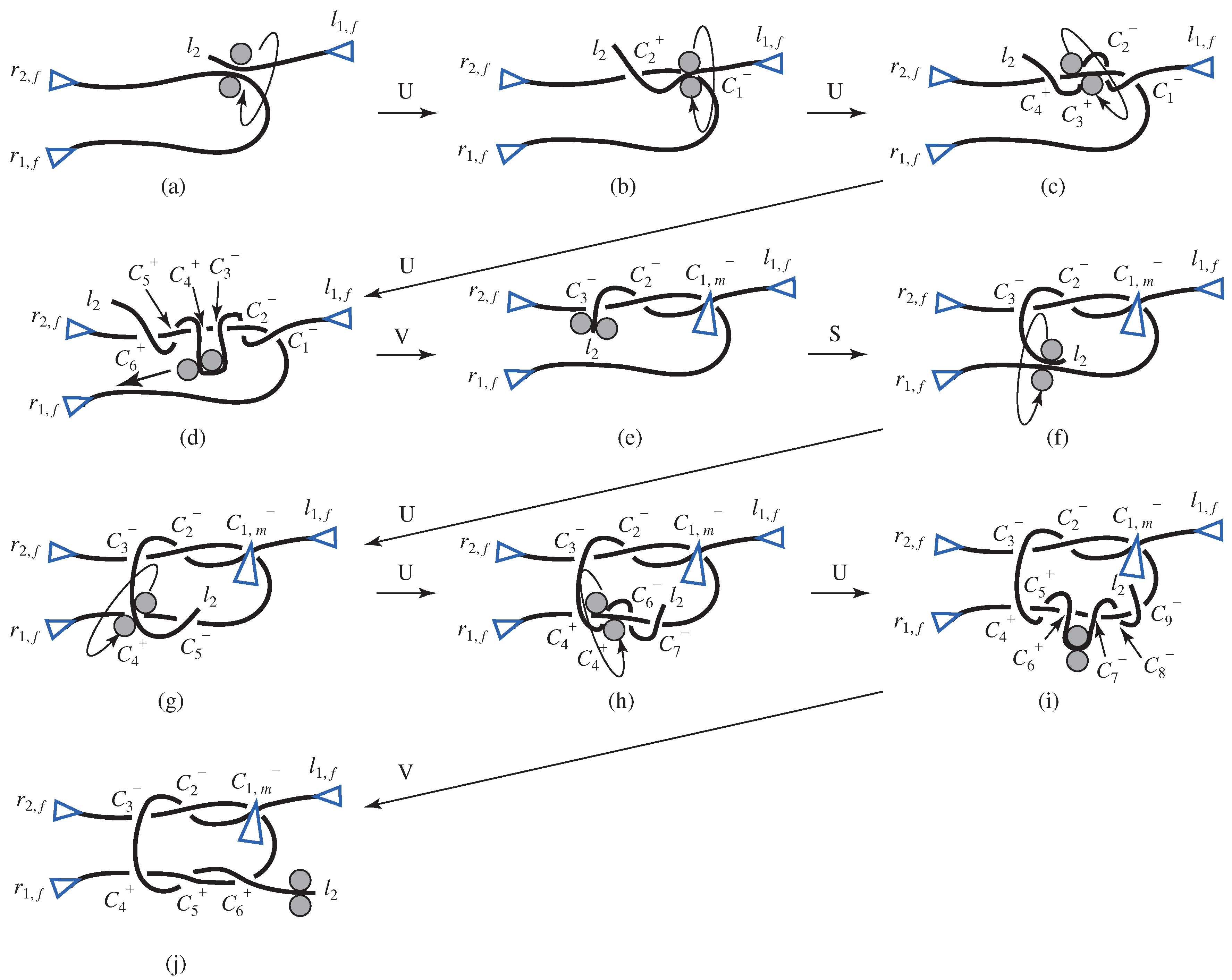
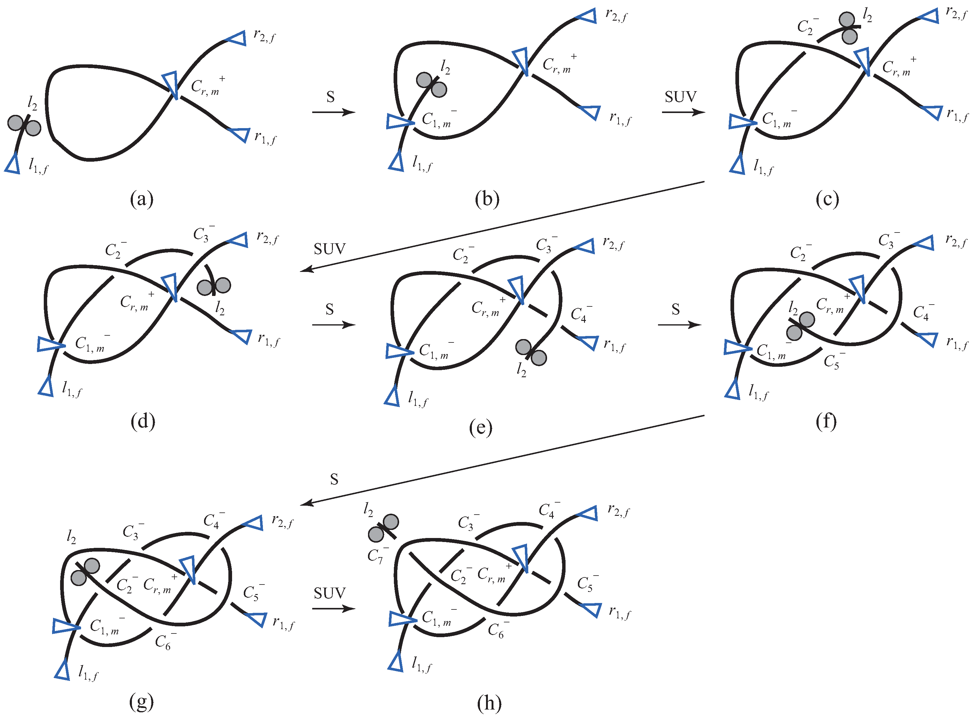
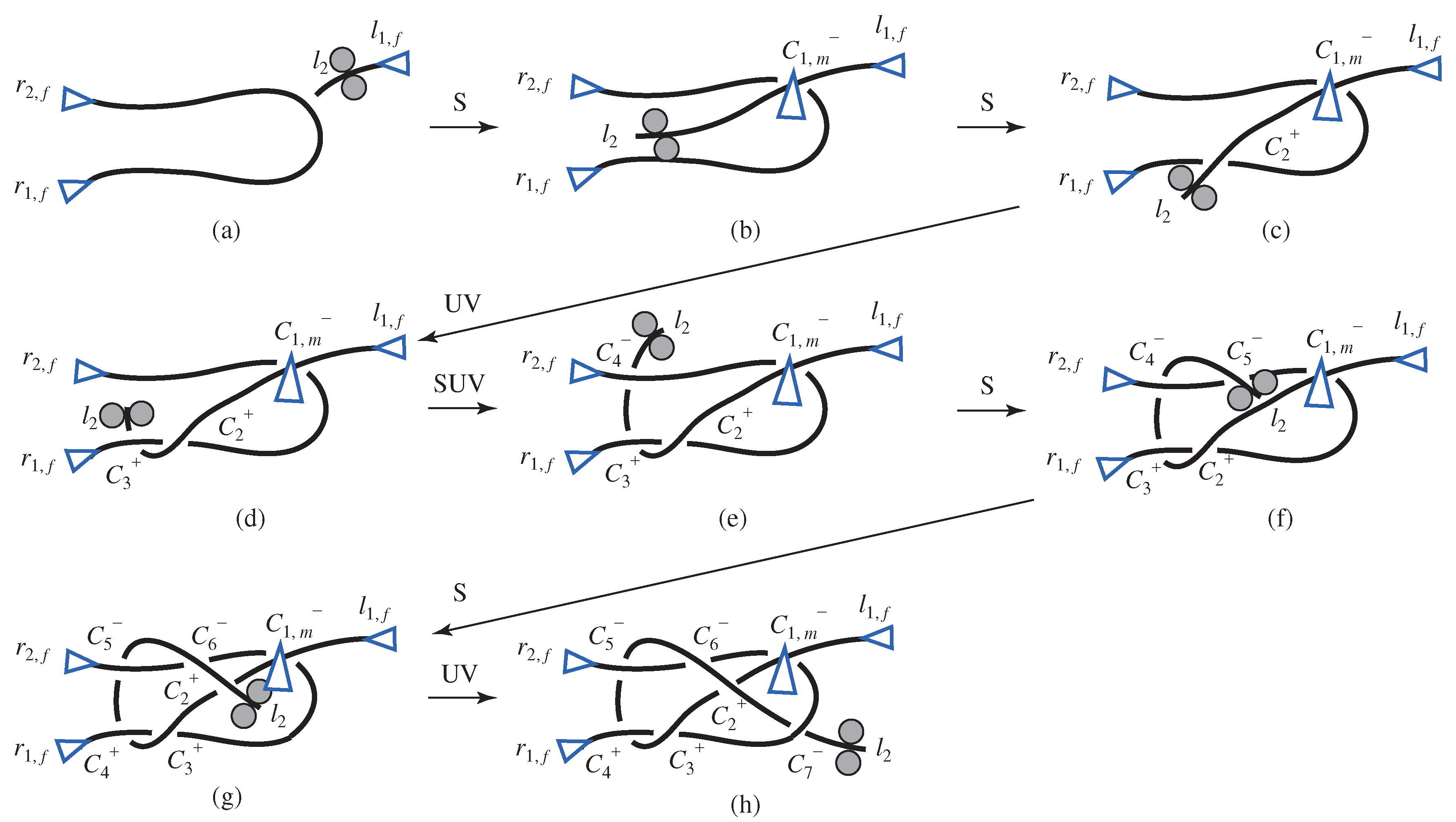
4.3. Knots with Two Ropes

In this section, we analyze knots formed with two ropes. Three kinds of knots are considered: (1) a sheet bend, (2) a square knot and (3) a granny knot.
The left end and the right end of one rope are represented by l 1 and l 2 , and the left end and the right end of the other rope are represented by r 1 and r 2 . The description of the intersections on the two ropes is performed in the order from the initial location. In the analysis, the knot is unraveled from l 2 .

4.3.1. Sheet Bend

The one rope described by r 1 , f , r 2 , f is fixed at the initial state, as shown in Figure 24a. The intersection C 1 is produced by rope moving (Figure 24b), in which the intersection is fixed, and a description of this fixation is added. To create an even-numbered intersection with sign + (second intersection), rope moving is performed, and the intersection C 2 + is created (Figure 24c). Next, the intersection C 3 + , which is an odd-numbered intersection with sign + (third intersection), is created by rope permutation and rope pulling (Figure 24d). Then, the intersection C 4 , which is an even-numbered intersection with sign − (fourth intersection), is made by rope moving, rope permutation and rope pulling (Figure 24e). Moreover, the intersection C 5 , which is an odd-numbered intersection with sign − (fifth intersection), is created by rope moving (Figure 24f), and the intersection C 2 + , which is an even-numbered intersection with sign + (sixth intersection), is also created by rope moving (Figure 24g). Finally, to create an odd-numbered intersection with sign − (seventh intersection), rope permutation and rope pulling are executed, then the intersection C 7 is produced. As a result, a sheet bend knot is completed (Figure 24h).
l 1 , f l 2 r 1 , f r 2 , f ( a )
l 1 , f C 1 , m l 2 r 1 , f C 1 , m r 2 , f ( b )
l 1 , f C 1 , m C 2 + l 2 r 1 , f C 2 + C 1 , m r 2 , f ( c )
l 1 , f C 1 , m C 2 + C 3 + l 2 r 1 , f C 3 + C 2 + C 1 , m r 2 , f ( d )
l 1 , f C 1 , m C 2 + C 3 + C 4 l 2 r 1 , f C 3 + C 2 + C 1 , m C 4 r 2 , f ( e )
l 1 , f C 1 , m C 2 + C 3 + C 4 C 5 l 2 r 1 , f C 3 + C 2 + C 1 , m C 5 C 4 r 2 , f ( f )
l 1 , f C 1 , m C 2 + C 3 + C 4 + C 5 C 6 C 2 + l 2 r 1 , f C 4 + C 3 + C 1 , m C 6 C 5 r 2 , f ( g )
l 1 , f C 1 , m C 2 + C 3 + C 4 + C 5 C 6 C 2 + C 7 l 2 r 1 , f C 4 + C 3 + C 7 C 1 , m C 6 C 5 r 2 , f ( h )

4.3.2. Square Knot

The initial state is set as shown in Figure 25a, which is the same as the sheet bend knot. By performing rope permutation three times and rope pulling one time, the intersections C 1 , C 2 and C 3 are created (Figure 25e). Here, the first intersection is fixed, and the description of the fixation is added. Next, the state shown in Figure 25f is obtained by rope moving. Lastly, by performing rope permutation three times and rope pulling one time, the intersections C 4 + , C 5 + and C 6 + are created, thus completing the square knot (Figure 25j).
l 1 , f l 2 r 1 , f r 2 , f ( a )
l 1 , f C 1 , m C 2 C 3 l 2 r 1 , f C 1 , m C 2 C 3 r 2 , f ( e )
l 1 , f C 1 , m C 2 C 3 C 4 + C 5 + C 6 + l 2 r 1 , f C 4 + C 5 + C 6 + C 1 , m C 2 C 3 r 2 , f ( j )

4.3.3. Granny Knot

By creating the intersection C r , m + , the initial state is set as shown in Figure 26a. Then, the intersection C 1 is made by rope moving (Figure 26b). Here, the first intersection is fixed, and the description of the fixation is added. Next, the intersection C 2 is created by rope permutation and rope pulling (Figure 26c). Moreover, the intersection C 3 is created by rope permutation and rope pulling (Figure 26d), and the intersection C 4 is also made by rope moving (Figure 26e). The intersections C 5 , C 6 and C 2 are created by rope moving in sequence (Figure 26g). Finally, the intersection C 7 is created by rope permutation and rope pulling, thus completing the granny knot (Figure 26h).
l 1 , f l 2 r 1 , f C r , m + C r , m + r 2 , f ( a )
l 1 , f C 1 , m l 2 r 1 , f C r , m + C 1 , m C r , m + r 2 , f ( b )
l 1 , f C 1 , m C 2 l 2 r 1 , f C r , m + C 2 C 1 , m C r , m + r 2 , f ( c )
l 1 , f C 1 , m C 2 C 3 l 2 r 1 , f C r , m + C 2 C 1 , m C r , m + C 3 r 2 , f ( d )
l 1 , f C 1 , m C 2 C 3 C 4 l 2 r 1 , f C 4 C r , m + C 2 C 1 , m C r , m + C 3 r 2 , f ( e )
l 1 , f C 1 , m C 2 C 3 C 4 C 5 l 2 r 1 , f C 4 C r , m + C 2 C 1 , m C 5 C r , m + C 3 r 2 , f ( f )
l 1 , f C 1 , m C 2 C 3 C 4 C 5 C 6 C 2 l 2 r 1 , f C 5 C r , m + C 3 C 1 , m C 6 C r , m + C 4 r 2 , f ( g )
l 1 , f C 1 , m C 2 C 3 C 4 C 5 C 6 C 2 C 7 l 2 r 1 , f C 5 C r , m + C 3 C 7 C 1 , m C 6 C r , m + C 4 r 2 , f ( h )

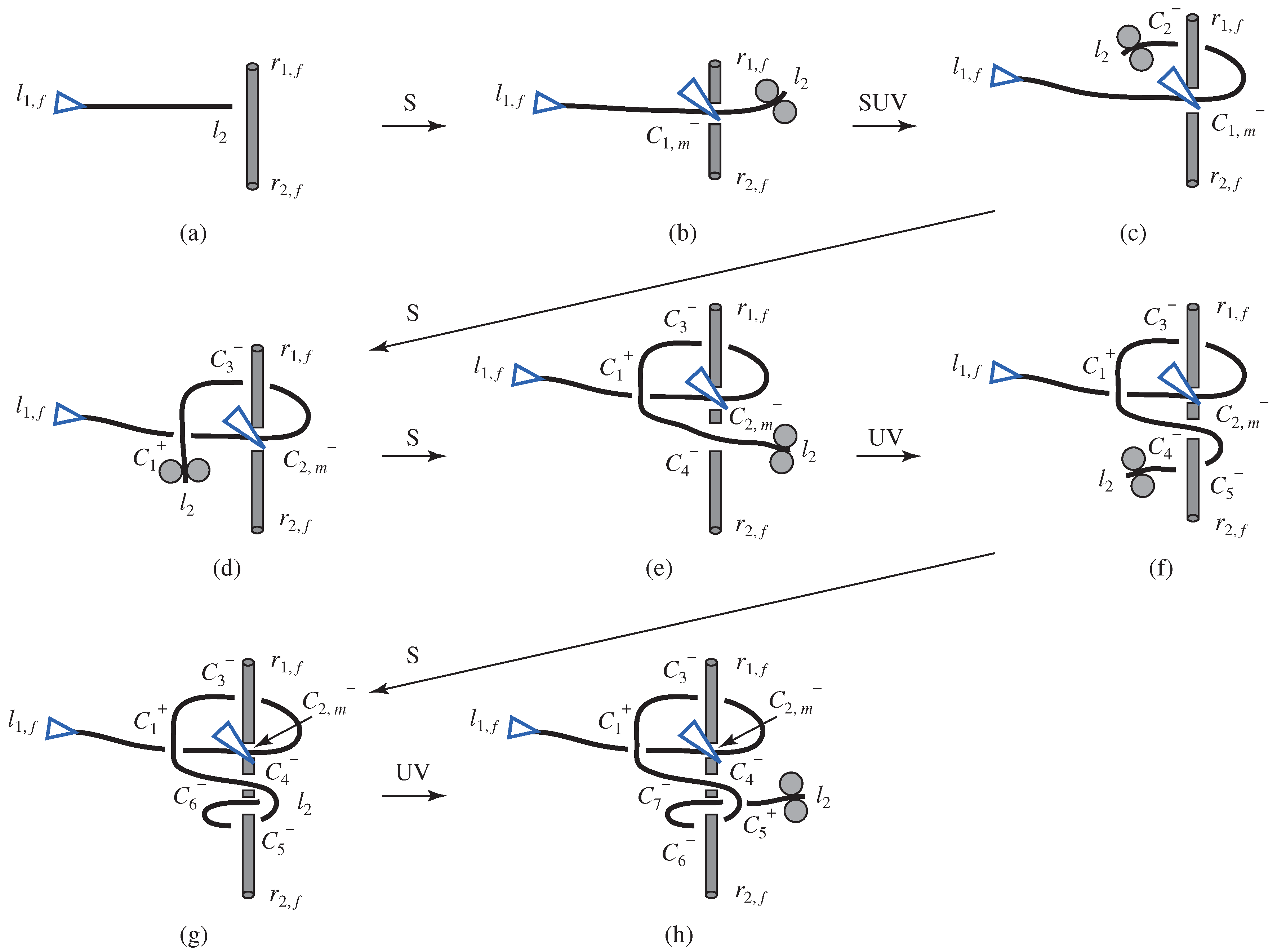
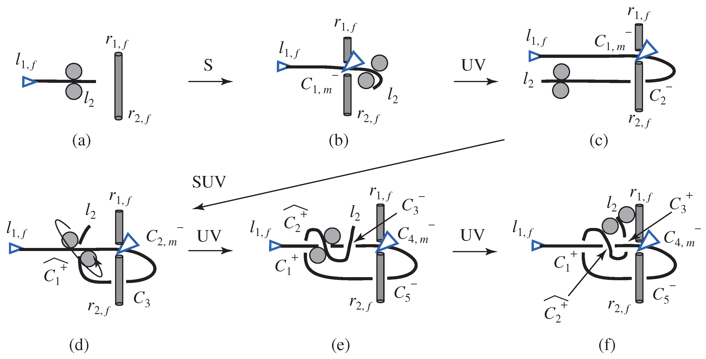
4.4. Knot with Single Rope and Object
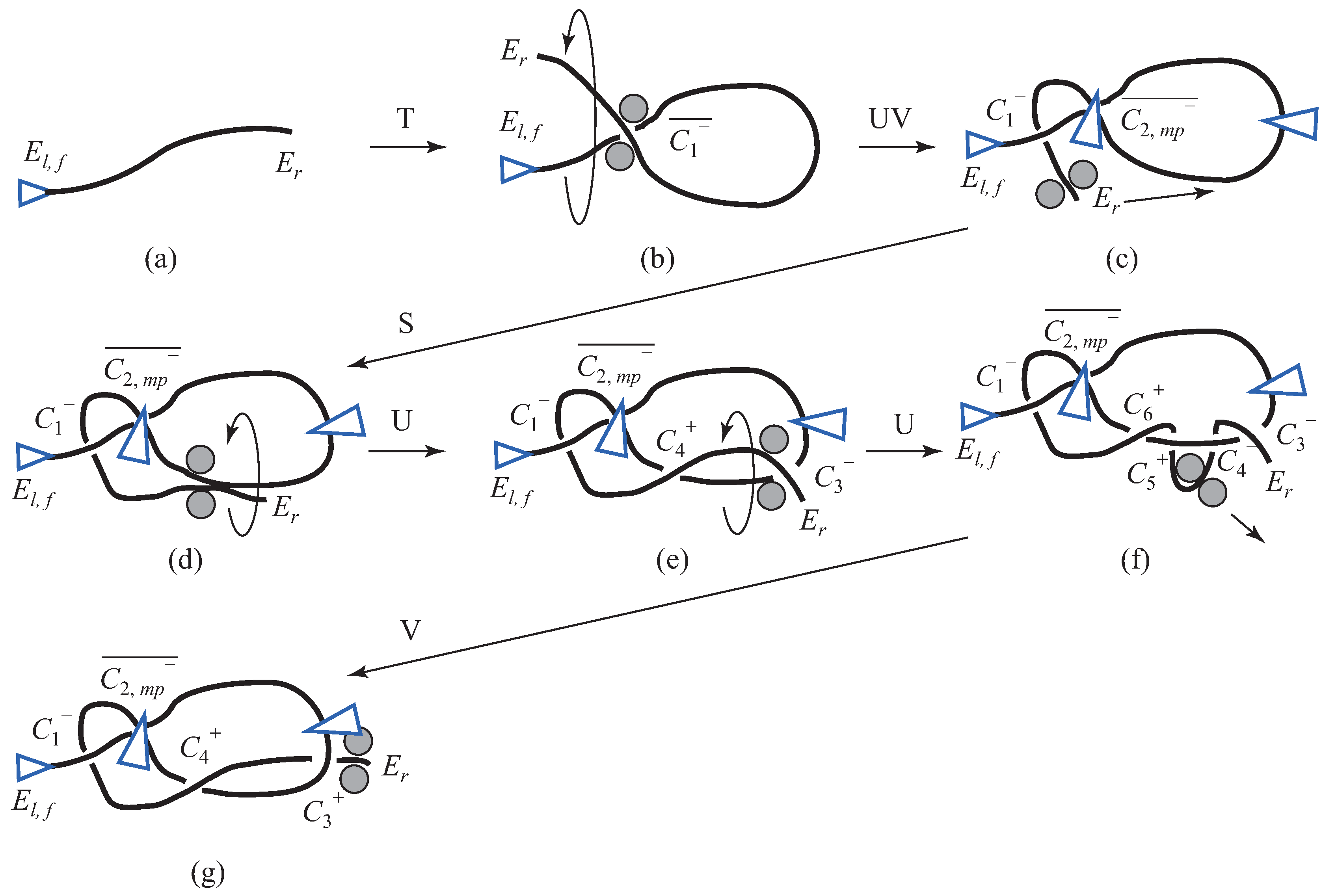
Here, we discuss a knot formed with a single rope and an object. As representative examples of such knots, we analyze: (1) a half hitch and (2) a clove hitch.
The left end and the right end of the rope are represented by l 1 and l 2 , and the left end and the right end of the object are represented by r 1 and r 2 , like the descriptions of the knots formed with two ropes. The description of intersections on the rope and the object is performed in order from the initial location.

4.4.1. Half Hitch

First, the intersection C 1 is created by rope moving (Figure 27b), and the fixation is performed and the description of the fixation added. The intersection C 2 , which is an even-numbered intersection with sign − (second intersection), is created by rope permutation and rope pulling (Figure 27c). Next, the intersection C 1 + , which is an odd-numbered intersection with sign + (third intersection), is also created (Figure 27d). Finally, rope permutation is performed two times and rope pulling one time to complete the half hitch (Figure 27f).
l 1 , f l 2 r 1 , f r 2 , f ( a )
l 1 , f C 1 , m l 2 r 1 , f C 1 , m r 2 , f ( b )
l 1 , f C 1 , m C 2 l 2 r 1 , f C 1 , m C 2 r 2 , f ( c )
l 1 , f C 1 + ^ C 2 , m C 3 C 1 + ^ l 2 r 1 , f C 2 , m C 3 r 2 , f ( d )
l 1 , f C 1 + C 2 + ^ C 3 C 4 , m C 5 C 1 C 2 + ^ C 3 l 2 r 1 , f C 4 , m C 5 r 2 , f ( e )
l 1 , f C 1 + C 2 + ^ C 3 + C 4 , m C 5 C 1 + C 2 + ^ C 3 + l 2 r 1 , f C 4 , m C 5 r 2 , f ( f )

4.4.2. Clove Hitch

The first intersection C 1 is created by rope moving, as shown in Figure 28b, and the description of the fixation of the first intersection is added. Secondly, the intersection C 2 , which is an even-numbered intersection with sign − (second intersection), is created by rope permutation and rope pulling (Figure 28c). Two intersections C 1 + and C 4 are produced by rope moving (Figure 28e). The intersection C 5 is created by rope permutation and rope pulling, and the intersection C 6 is also created by rope moving (Figure 28g). Finally, the intersection C 5 + is created by rope permutation and rope pulling, thus completing the clove hitch (Figure 28h).
Although multiple procedures can be obtained and these procedure may not be identified in conventional methods, our proposed method can always obtain one procedure. This is the advantage of our proposed method. In addition, the proposed method considers the robot mechanism and the robot motion required for the procedure, and therefore, it is considered that the procedure obtained by the proposed method can be easily implemented on a robot system.
l 1 , f l 2 r 1 , f r 2 , f ( a )
l 1 , f C 1 , m l 2 r 1 , f C 1 , m r 2 , f ( b )
l 1 , f C 1 , m C 2 l 2 r 1 , f C 2 C 1 , m r 2 , f ( c )
l 1 , f C 1 + C 2 , m C 3 C 1 + l 2 r 1 , f C 3 C 2 , m r 2 , f ( d )
l 1 , f C 1 + C 2 , m C 3 C 1 + C 4 l 2 r 1 , f C 3 C 2 , m C 4 r 2 , f ( e )
l 1 , f C 1 + C 2 , m C 3 C 1 + C 4 C 5 l 2 r 1 , f C 3 C 2 , m C 4 C 5 r 2 , f ( f )
l 1 , f C 1 + C 2 , m C 3 C 1 + C 4 C 5 C 6 l 2 r 1 , f C 3 C 2 , m C 4 C 6 C 5 r 2 , f ( g )
l 1 , f C 1 + C 2 , m C 3 C 1 + C 4 C 5 + C 6 C 7 C 5 + l 2 r 1 , f C 3 C 2 , m C 4 C 7 C 6 r 2 , f ( h )

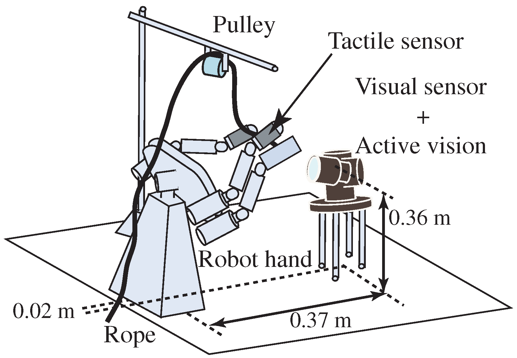
5. Knotting Manipulation by a High-Speed Robot System

Here, we show actual knotting manipulation by a high-speed robot system, which consisted of a high-speed multi-fingered hand [15], high-speed tactile sensors [16], a high-speed vision system including image processing [17] and an active vision system for gaze control.
We formed two kinds of knots, namely an overhand knot and a half hitch. Concrete explanations about the robot motion and the sensory feedback control method for performing the manipulation skills were described in a previous paper [1,12].

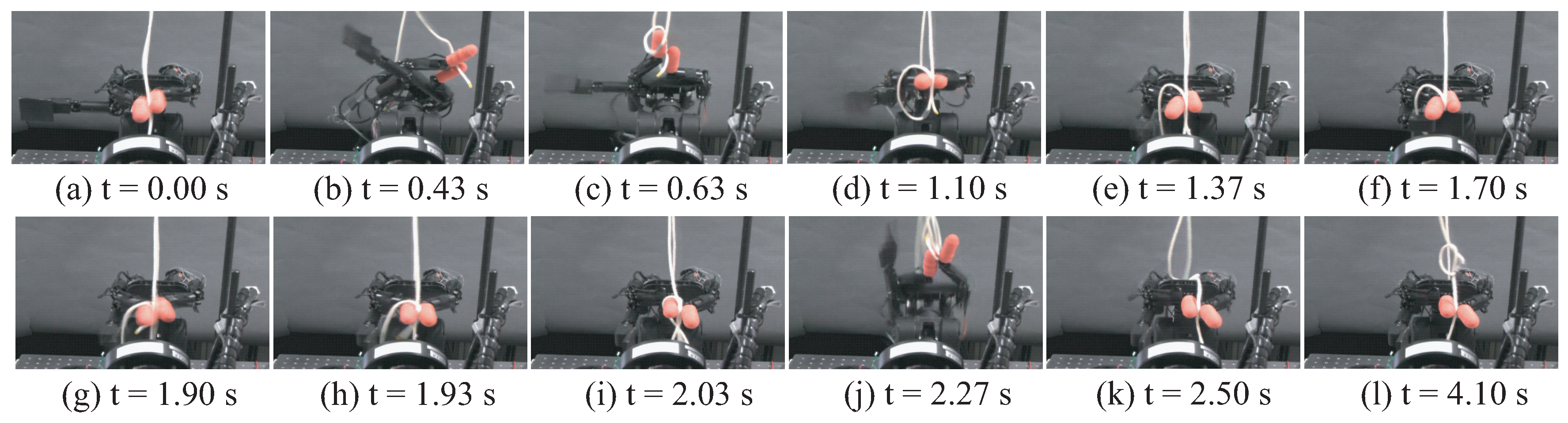
5.1. Experimental Result for Overhand Knot

Figure 29 shows the experimental setup for overhand knot manipulation, and Figure 30 shows the experimental result. In Figure 30a–e, the loop production was performed using wrist motion. Figure 30f,g shows the rope pushing motion for rope permutation. Figure 30h,i shows the rope permutation, and Figure 30j–l shows rope pulling. As a result, the overhand knot could be achieved successfully by the robot system.

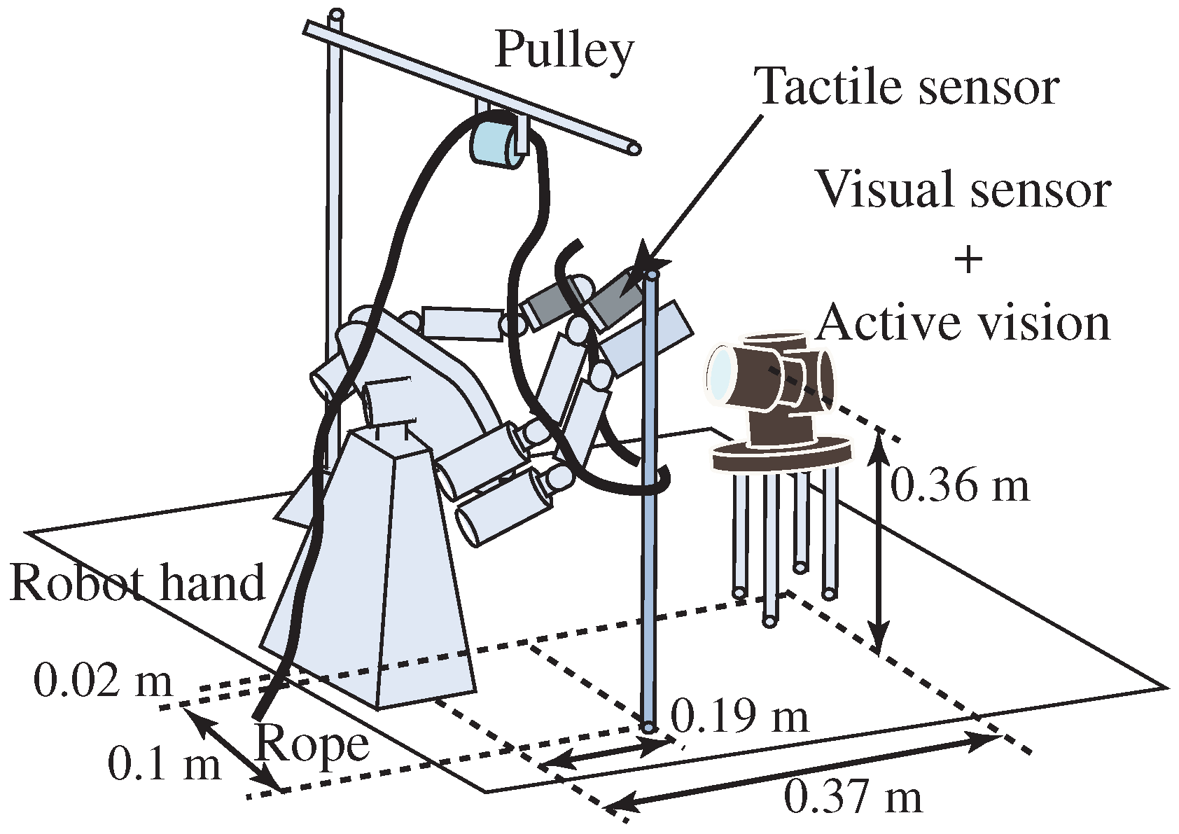
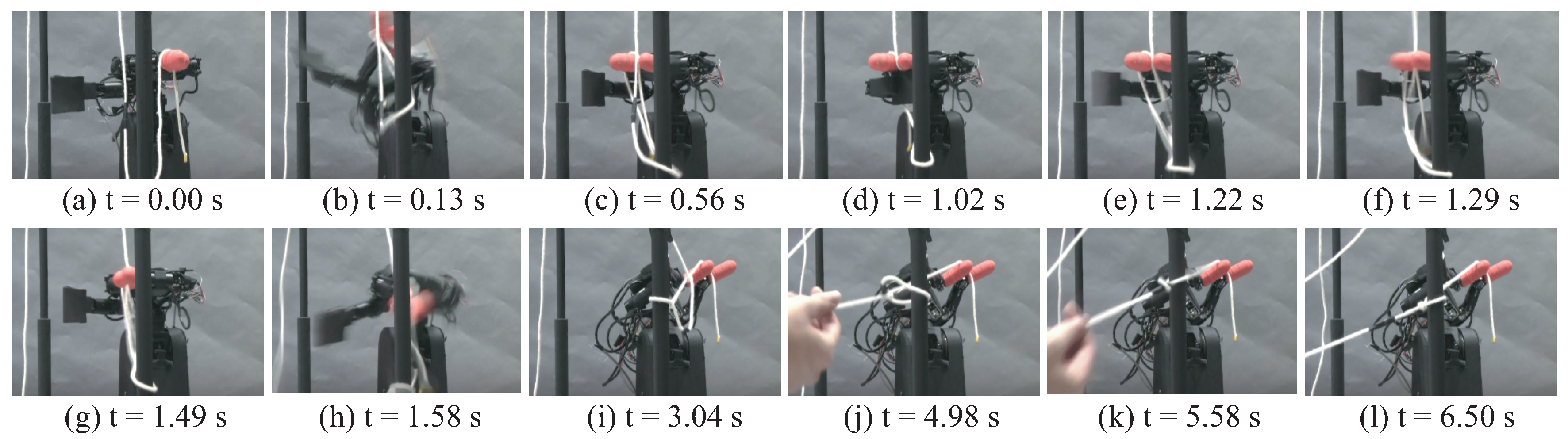
5.2. Experimental Result of Half Hitch

Figure 31 shows an overview of the experimental system for half hitch manipulation. In this experiment, the robot system did not have a translational motion mechanism, and therefore, the state in which the rope moving is finished (Figure 27c) was set at the initial state. Figure 32 shows the experimental result. Figure 32a depicts the initial state; Figure 32b,c illustrate the loop production; Figure 32d illustrates rope pushing for rope permutation; Figure 32e–g shows rope permutation; and Figure 32h,i shows rope pulling. Finally, as shown in Figure 32j–l, a human strengthened the knot in order to make the resulting half hitch more visible.
From these experimental results, we confirmed that the proposed method is effective for knotting manipulation, and two knots were achieved successfully by using our proposed method and the robot system. The results can be seen on our web site [18,19].

6. Conclusions

Our goal was to achieve knotting of a flexible rope as an example of dexterous manipulation of a linear flexible object. A summary of the work described in this article is as follows:
  • We analyzed the knotting motion of a human hand to identify the necessary knotting skills. Then, we proposed a knot description methodology and a method of obtaining the production process of a knot based on combinations of these skills.
  • We suggested a knotting strategy that does not depend on the flexible characteristics of the rope. A real-time tactile and visual sensory feedback control method was proposed to improve the success rate and robustness for various ropes.
  • We demonstrated experimental results achieved by a high-speed multi-fingered hand system.
In the future, we plan to achieve several other knots in addition to the overhand knot and half hitch demonstrated here, according to the procedure obtained from the analysis result described in this paper.

Acknowledgments

This work was supported by JSPS KAKENHI Grant Numbers JP24220005, JP24680020.

Author Contributions

Y.Y.analyzed the knotting plans and performed the experiments using the high-speed robot system. A.N. proposed the analysis method of the knotting planning. M.I. developed the high-speed robot system including the high-speed vision. M.S developed the high-speed tactile sensor.

Conflicts of Interest

The authors declare no conflict of interest.

References

  1. Yamakawa, Y.; Namiki, A.; Ishikawa, M.; Shimojo, M. One-handed Knotting of a Flexible Rope with a High-speed Multifingered Hand having Tactile Sensors. In Proceedings of the IEEE/RSJ International Conference on Intelligent Robots and Systems, San Diego, CA, USA, 29 October–2 November 2007; pp. 703–708. [Google Scholar]
  2. Inoue, H.; Inaba, M. Hand-Eye Coordination in Rope Handling; Robotics Research: The First International Symposium; MIT Press: Cambridge, MA, USA, 1984; pp. 163–174. [Google Scholar]
  3. Matsuno, T.; Fukuda, T.; Arai, F. Flexible Rope Manipulation by Dual Manipulator System Using Vision Sensor. In Proceedings of the IEEE/ASME International Conference on Advanced Intelligent Mechatronics, Como, Italy, 8–12 July 2001; pp. 677–682. [Google Scholar]
  4. Saha, M.; Isto, P. Motion Planning for Robotic Manipulation of Deformable Linear Object. In Proceedings of the IEEE International Conference on Robotics and Automation, Orlando, FL, USA, 15–19 May 2006; pp. 2478–2484. [Google Scholar]
  5. Morita, T.; Takamatsu, J.; Ogawara, K.; Kimura, H.; Ikeuchi, K. Knot Planning from Observation. In Proceedings of the IEEE International Conference on Robotics and Automation, Taipei, Taiwan, 14–19 September 2003; pp. 3887–3892. [Google Scholar]
  6. Wakamatsu, H.; Arai, E.; Hirai, S. Knotting/Unknotting Manipulation of Deformable Linear Objects. Int. J. Robot. Res. 2006, 25, 371–395. [Google Scholar] [CrossRef]
  7. Onda, H.; Kudoh, S.; Suehiro, T. Handling and Describing String-Tying Operations Based on Metrics Using Segments between Crossing Sections. IEEE Robot. Autom. Lett. 2016, 1, 375–382. [Google Scholar] [CrossRef]
  8. Vinh, T.V.; Tomizawa, T.; Kudoh, S.; Suehiro, T. Knotting task execution based a hand-rope relation. Adv. Robot. 2017, 31, 570–579. [Google Scholar] [CrossRef]
  9. Wang, W.; Balkcom, D. Towards Arranging and Tightening Knots and Unknots with Fixtures. IEEE Trans. Autom. Sci. Eng. 2015, 12, 1318–1331. [Google Scholar] [CrossRef]
  10. Wang, W.; Balkcom, D. Towards tying knots precisely. In Proceedings of the IEEE International Conference on Robotics and Automation, Stockholm, Sweden, 16–21 May 2016; pp. 3639–3646. [Google Scholar]
  11. Yamakawa, Y.; Namiki, A.; Ishikawa, M.; Shimojo, M. Knotting Manipulation of a Flexible Rope with a High-speed Multifingered Hand System based on Skill Synthesis. In Proceedings of the IEEE/RSJ International Conference on Intelligent Robots and Systems, Nice, France, 22–26 September 2008; pp. 2691–2696. [Google Scholar]
  12. Yamakawa, Y.; Namiki, A.; Ishikawa, M.; Shimojo, M. One-handed Knotting of a Linear Flexible Object based on Reconfigurable Skill Synthesis Strategy. In Proceedings of the ASME/IFToMM International Conference on Reconfigurable Mechanisms and Robots, London, UK, 22–24 June 2009; pp. 486–493. [Google Scholar]
  13. Yamakawa, Y.; Namiki, A.; Ishikawa, M.; Shimojo, M. Knotting a Flexible Rope using a High-speed Multifingered Hand System based on Synthesis of Knotting Manipulation Skills. In Robotics 2010 Current and Future Challenges; InTech: Rijeka, Croatia, 2010; pp. 149–166. [Google Scholar]
  14. Adams, C.C. The Knot Book—An Elementary Introduction to the Mathematical Theory of Knots; American Mathematical Society: Providence, RI, USA, 2004. [Google Scholar]
  15. Namiki, A.; Imai, Y.; Ishikawa, M.; Kaneko, M. Development of a High-speed Multifingered Hand System and Its Application to Catching. In Proceedings of the IEEE/RSJ International Conference on Intelligent Robots and Systems, Las Vegas, NV, USA, 27–31 October 2003; pp. 2666–2671. [Google Scholar]
  16. Ishikawa, M.; Shimojo, M. A Method for Measuring the Center Position of a Two Dimensional Distributed Load Using Pressure-Conductive Rubber. Trans. Soc. Instrum. Control Eng. 1982, 18, 730–735. (In Japanese) [Google Scholar] [CrossRef]
  17. Nakabo, Y.; Ishikawa, M.; Toyoda, H.; Mizuno, S. 1 ms column parallel vision system and its application of high speed target tracking. In Proceedings of the International Conference on Robotics and Automation, San Francisco, CA, USA, 24–28 April 2000; pp. 650–655. [Google Scholar]
  18. Ishikawa Watanabe Laboratory, One Handed Knotting of flexible rope using a High-speed Multifingered Hand. Available online: http://www.k2.t.u-tokyo.ac.jp/fusion/Knotting/index-e.html (accessed on 20 August 2017).
  19. Ishikawa Watanabe Laboratory, Knotting manipulation based on skill synthesis. Available online: http://www.k2.t.u-tokyo.ac.jp/fusion/SkillSynthesis/index-e.html (accessed on 20 August 2017).
Figure 1. Manipulation model.
Symmetry 09 00194 g001
Figure 2. Concept of this research.
Symmetry 09 00194 g002
Figure 3. Problem setting.
Symmetry 09 00194 g003
Figure 4. One-handed knotting by a human.
Symmetry 09 00194 g004
Figure 5. Overview of manipulation skills. (a) Rope moving; (b) Loop production; (c) Rope permutation; (d) Rope pulling.
Symmetry 09 00194 g005
Figure 6. Intersection signs. (a) Counter clockwise: –; (b) Clockwise: +.
Symmetry 09 00194 g006
Figure 7. Grasp types. (a) Grasp type 1; (b) Grasp type 2.
Symmetry 09 00194 g007
Figure 8. Failure of rope permutation.
Symmetry 09 00194 g008
Figure 9. Rope moving. (a) Creation of one intersection; (b) Approach to other rope section.
Symmetry 09 00194 g009
Figure 10. Fixation location on rope moving. (a) Case of single rope; (b) Case of two ropes.
Symmetry 09 00194 g010
Figure 11. Loop production.
Symmetry 09 00194 g011
Figure 12. Rope permutation.
Symmetry 09 00194 g012
Figure 13. Rope pulling.
Symmetry 09 00194 g013
Figure 14. Permutation + pulling (I).
Symmetry 09 00194 g014
Figure 15. Permutation + pulling (II).
Symmetry 09 00194 g015
Figure 16. Permutation + pulling (III).
Symmetry 09 00194 g016
Figure 17. Constraint condition for the first intersection. (a) Single rope; (b) Two ropes.
Symmetry 09 00194 g017
Figure 18. Flowchart for the unraveling procedure.
Symmetry 09 00194 g018
Figure 19. Flowchart for the knotting procedure.
Symmetry 09 00194 g019
Figure 20. Unraveling of an overhand knot.
Symmetry 09 00194 g020
Figure 21. Knotting of an overhand knot.
Symmetry 09 00194 g021
Figure 22. Figure-eight knot.
Symmetry 09 00194 g022
Figure 23. Stevedore’s knot.
Symmetry 09 00194 g023
Figure 24. Sheet bend.
Symmetry 09 00194 g024
Figure 25. Square knot.
Symmetry 09 00194 g025
Figure 26. Granny knot.
Symmetry 09 00194 g026
Figure 27. Half hitch.
Symmetry 09 00194 g027
Figure 28. Clove hitch.
Symmetry 09 00194 g028
Figure 29. Overall system of the overhand knot experiment.
Symmetry 09 00194 g029
Figure 30. Continuous photographs of the overhand knot experiment. (a) t = 0.00 s; (b) t = 0.43 s; (c) t = 0.63 s; (d) t = 1.10 s; (e) t = 1.37 s; (f) t = 1.70 s; (g) t = 1.90 s; (h) t = 1.93 s; (i) t = 2.03 s; (j) t = 2.27 s; (k) t = 2.50 s; (l) t = 4.10 s.
Symmetry 09 00194 g030
Figure 31. Overall system for the half hitch experiment.
Symmetry 09 00194 g031
Figure 32. Continuous photographs of the half hitch experiment. (a) t = 0.00 s; (b) t = 0.13 s; (c) t = 0.56 s; (d) t = 1.02 s; (e) t = 1.22 s; (f) t = 1.29 s; (g) t = 1.49 s; (h) t = 1.58 s; (i) t = 3.04 s; (j) t = 4.98 s; (k) t = 5.58 s; (l) t = 6.50 s.
Symmetry 09 00194 g032
Table 1. Rule of manipulation skills.
Production of IntersectionManipulation Skill
Add an intersection ‘−’ in case that
there is no intersection in a single ropeLoop production (T)
Add an intersection ‘−’ : intersection of odd numberRope moving (S)
: intersection of even numberRope permutation + Rope pulling (UV)
Add an intersection ‘+’ : intersection of odd numberRope permutation + Rope pulling (UV)
: intersection of even numberRope moving (S)
Add two intersectionsRope permutation (U)
Change cross sign of intersectionRope permutation + Rope pulling (UV)
Delete intersections from one intersection to E r or l 2 Rope pulling (V)

