Increasing the Fine Flaky Graphite Recovery in Flotation via a Combined MultipleTreatments Technique of Middlings


1
School of Chemical Engineering and Energy, Zhengzhou University, Zhengzhou 450001, China
2
School of Resources and Environmental Engineering, Wuhan University of Technology, Luoshi Road 122, Wuhan 430070, China
*
Author to whom correspondence should be addressed.
Minerals 2017, 7(11), 208; https://doi.org/10.3390/min7110208
Submission received: 9 October 2017
/
Revised: 19 October 2017
/
Accepted: 19 October 2017
/
Published: 1 November 2017
Abstract
:As the residual flaky graphite ores become miscellaneous and fine, a single treatment technique for the middlings from the flotation process of graphite ore cannot efficiently recover the valuable graphite in the multistage grinding-flotation technology. In the study, the existence form of graphite and relationship of graphite with the associated gangue minerals were estimated by optical microscope analysis. The results indicated that the fine flaky graphite particles embedded with gangue minerals like a honeycomb, making it difficult to be beneficiated using the typical flotation technique. A combination technique of individual process and concentrated returning for the treatment of middlings was used to increase the graphite recovery based on the co-existing relationship between graphite and gangue minerals in the middlings. The graphite recovery of the final concentrate upgraded from 51.81% to 91.14% at a fixed carbon (FC) content of 92.01% by a beneficiation process consisted of once coarse (94.41% passing 74 μm) and rougher, five stages regrinding and six stages cleaning. The proposed treatment technique for middlings is of great significance to increase the recovery of fine flaky graphite.
1. Introduction
Graphite is one of the three forms of naturally found crystalline carbon [1]. In general, natural graphite was classified as flaky, lump and amorphous graphites according to the difference of crystalline morphology [2,3,4]. Graphite, considered to be one of the most important non-metallic minerals, is widely applied in foundry facings, refractories, lubricants, pencils, batteries, brake linings, bearings, conductive coatings and crucibles due to its unique physical and chemical properties [5].
Flaky graphite can be easily purified by flotation due to its high natural hydrophobicity [6,7]. Generally, the flaky graphite ore was purified via multi-stage grinding-flotation (as shown in Figure 1a) to prevent the graphite flakes from being destroyed during the following regrinding, and a large amount of middling was naturally produced in the process [8,9,10]. In the typical technique for graphite beneficiation, the treatment techniques for the graphite middlings contain concentrated returning (Figure 1b), returning step-by-step (Figure 1c), individual process (Figure 1d), etc. [11,12]. Concentrated middlings returning can simplify the flowsheet, but resulting in an adverse effect on the flotation when the amount of middling is large or great differences exist in the property of middlings [13]. Returning middlings step-by-step is adapted to enhance the recovery of the graphite ore with poor floatability [14]. It can dramatically reduce the amount of returning middlings, extra supplementary water, and the loads of concentration, rougher and scavenger, which benefits to the increase of the graphite recovery. However, when more mineral combinations exist in the middlings or the pulp concentration is high, the technique of returning middlings step-by-step can easily lead to a decline of the fixed carbon (FC) of the final concentrate [6]. Individual process of middling is to merge all or part of the middlings and process individually. The merged middlings can directly discard, directly refloat or individually regrinding and refloat according to their different properties [15]. The advantage of individual process is that it can reduce the amount of the circulating middlings, relieve the loads of rougher and scavenger, benefit to lower the FC content of tailing and improve the recovery. It is appropriate for the ore with graphite intercalated in the aperture of gangue minerals or wrapped by gangue minerals [16]. Specifically, the residual graphite ores present the characteristics of poor, miscellaneous and fine due to the excessive consumption [17]. The above methods for the treatment of middlings cannot efficiently recover the fine flaky graphite in the residual graphite ores individually, and the combined multiple treatment of middlings would be a potential method.
In this work, X-ray powder diffraction (XRD), X-ray fluorescence (XRF) and optical microscope were used to analyze the composition, flake size of graphite and symbiotic way of the graphite and gangue minerals. The optimum experimental parameters of rougher flotation were determined by a series of single-factor experiments. And a combined multiple treatments for the middlings was first proposed to increase the recovery of the fine flaky graphite based on the relationship of graphite with the associated gangue minerals.
2. Materials and Methods
2.1. Materials
200 kg of the fine flaky graphite ore, taken from Nanjiang in Sichuan province (China), was crushed by double toggle jaw crusher (PE400 × 250) to less than 2 mm. Then, some representative samples were obtained to study mineralogical and chemical compositions, and the other samples were used for flotation tests.
The X-ray fluorescence (XRF) analysis for the raw ore is given in Table 1, showing that the main compositions are SiO2, Al2O3, TFe2O3, CaO, K2O, MgO, SO3 and Na2O. In addition, the raw ore was analyzed 25.95% FC content.
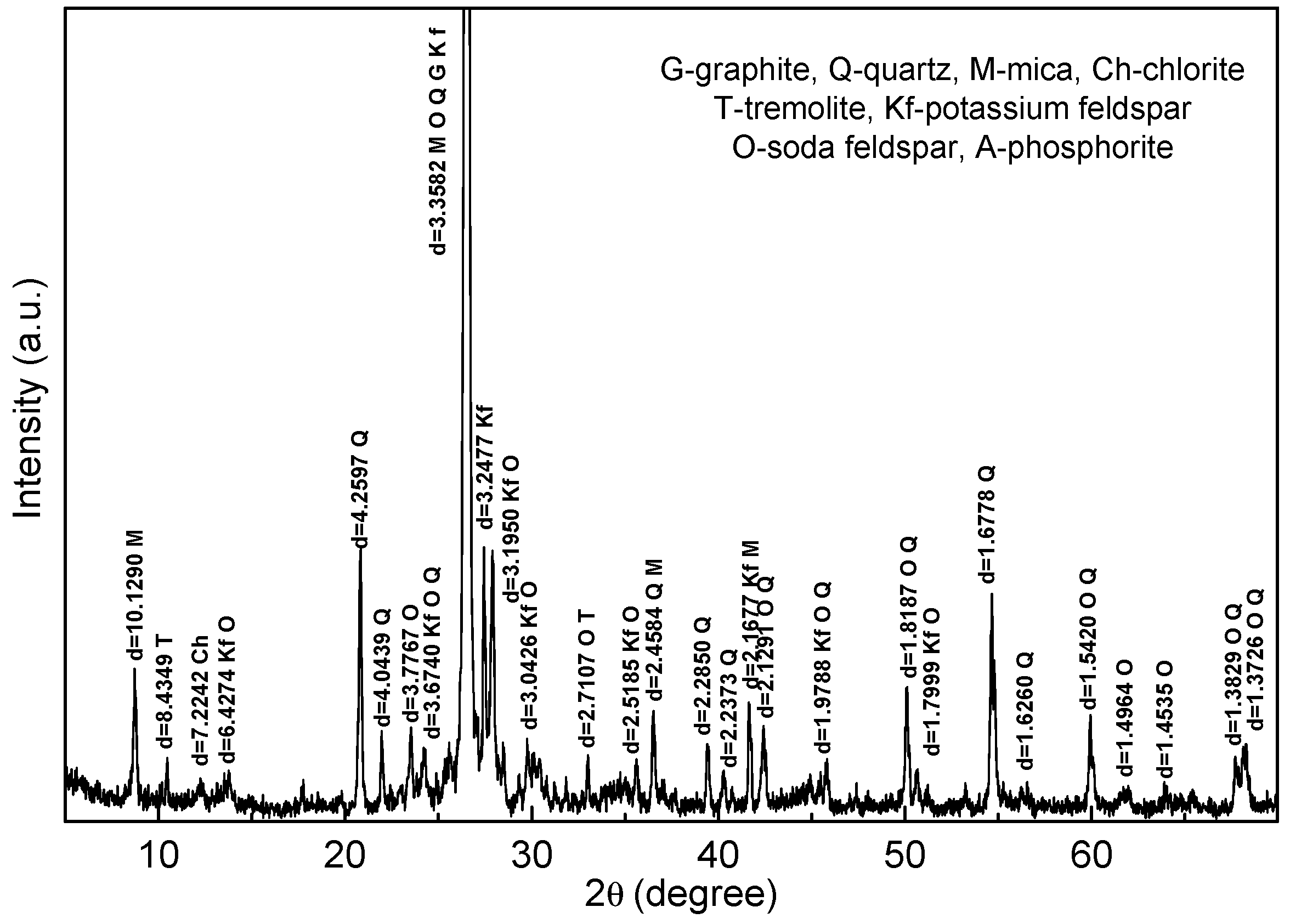
Figure 2 shows the XRD pattern of the raw ore, and the contents of the gangue minerals are summarized in Table 2. It can be seen that the main gangue minerals associated in the graphite ore are feldspar, quartz, mica, tremolite, chlorite and phosphorite.
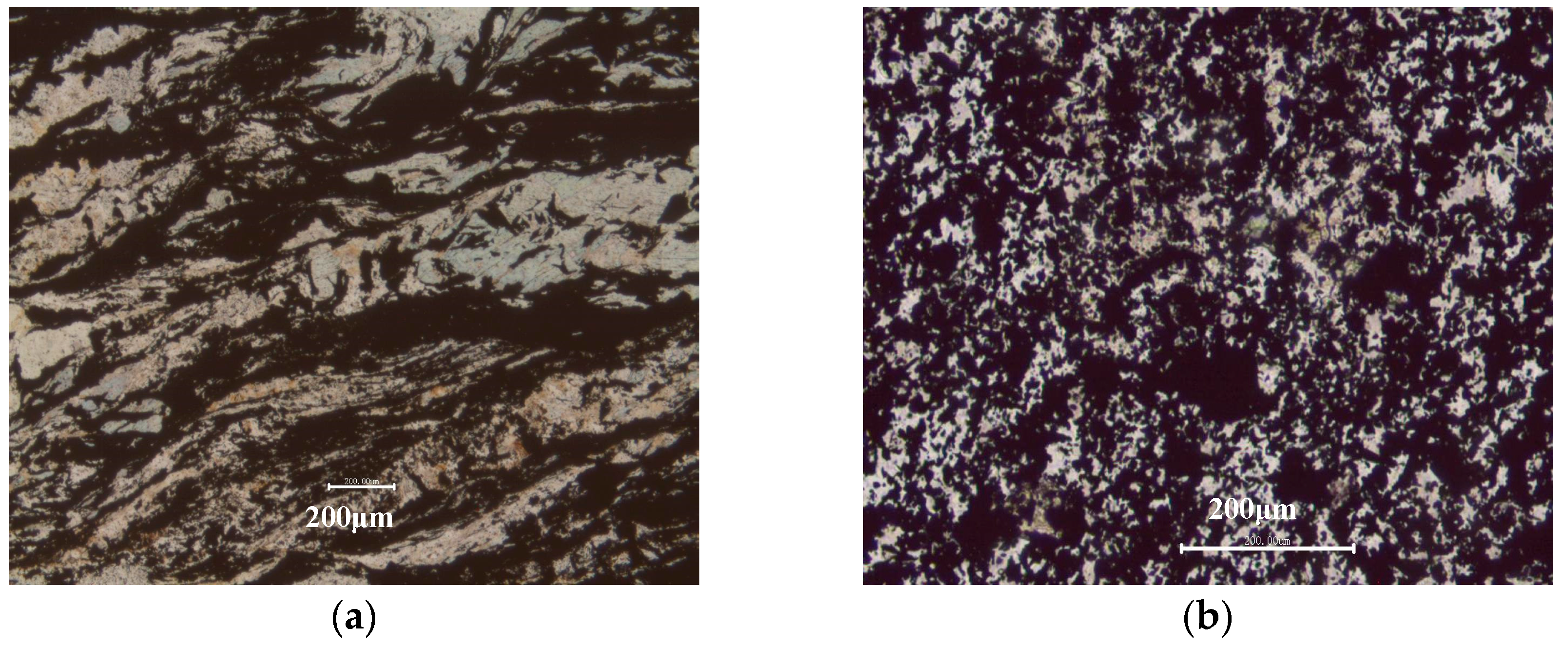
The morphology of the raw ore was observed, and the images are shown in Figure 3. It can be seen from Figure 3a that the graphite is directional distribution and the graphite stripe presents to be puckered. The part of graphite could be easily dissociated from the gangue minerals via crushing and multistage grinding. Moreover, Figure 3b shows that the other part of graphite is embedded with gangue minerals like a honeycomb, and the fine intertexture of graphite and gangue minerals makes full individual liberation via mechanical method very difficult, which also leads to a reduction of the FC content and recovery of the final graphite concentrate.
2.2. Methods
Chemical compositions of the raw ore were determined via a X-ray fluorescence Spectrometer (AXIOS, PANalytical. B.V, Almelo, The Netherlands). Compositions of the raw ore were identified using an advance X-ray diffractometer (D8, Bruker, Karlsruhe, Germany) with Cu Kα radiation (k = 1.5406 nm) at 40 kV and 100 mA. The morphology of the raw ore was observed using optical microscope (A2 pol, Leica, Wetzlar, Germany). More than ten blocks of rough crushed ore were chosen randomly to prepare polished sections and thin sections for the study, and the direction of cutting sections for the samples are typically highly anisotropic. The merged middlings mixture was washed with ethyl alcohol and sandwiched into a pair of micro slide prior to observe its morphology. The FC content (wt %) was analyzed based on the Chinese standard method (GB/T3521-2008).
The raw ore was divided into 250 g each for flotation tests. Before flotation, the sample was first rough grinded in XMQ-67Φ240×90 conical ball mill to the desired fineness. Bench-scale laboratory flotation tests were carried out in a XFD II mechanically agitated flotation machine with a 1.0 L cell at an impeller speed of 1400 rpm, and the flotation time was 5 min over the whole process. The regrinding was performed in XMQ-67Φ150×50 conical ball mill. Kerosene and terpenic oil purchased from Kermel Chemical Reagent Co. (Tianjin, China) were used as collector and frother, respectively, and the pH value of the pulp in rougher flotation was adjusted by lime obtained from Tianjin Dingshengxin Chemical Industry Co., Ltd. (Tianjin, China).
3. Results and Discussion
3.1. Experimental Parameters of Rougher Flotation
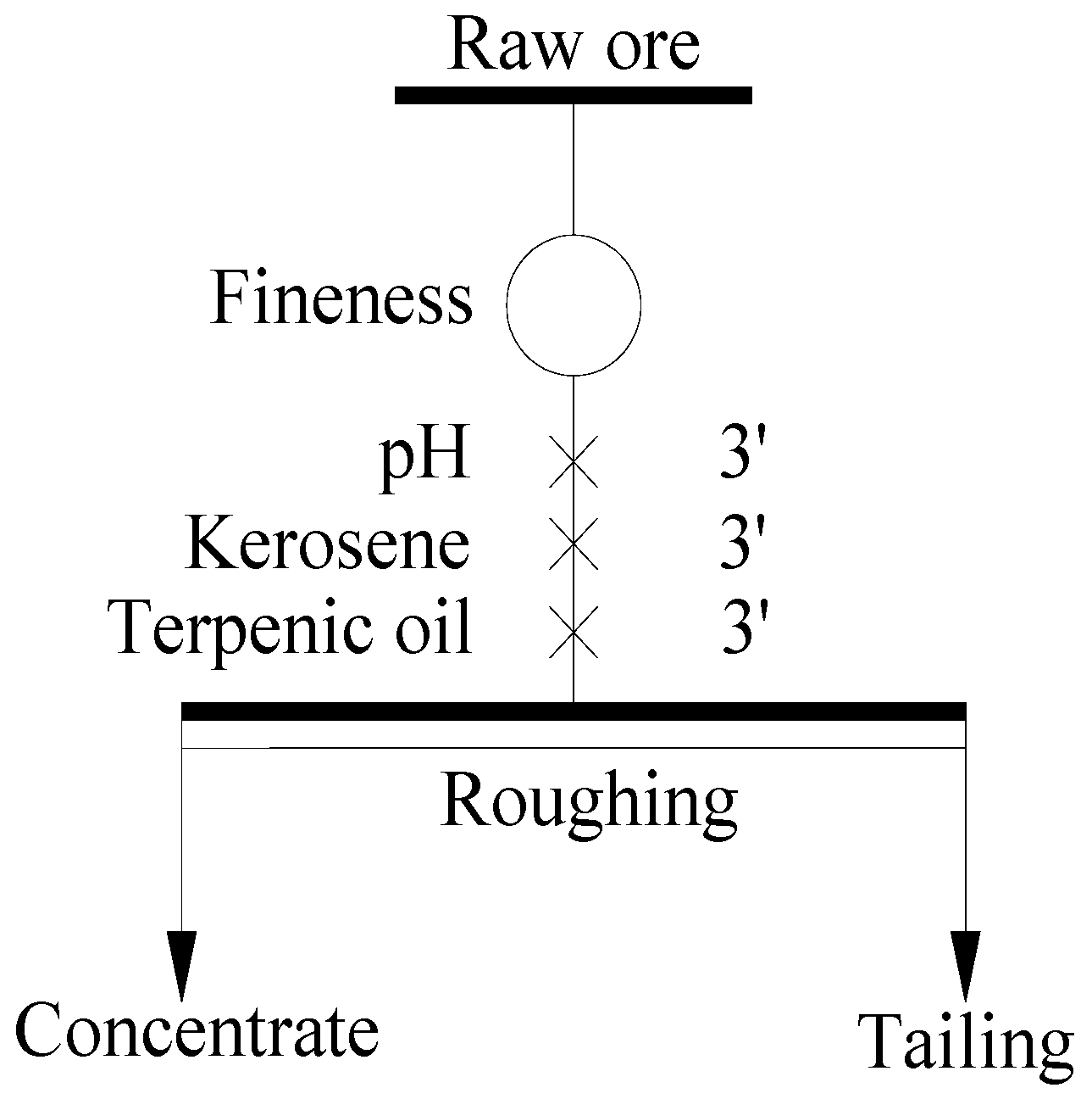
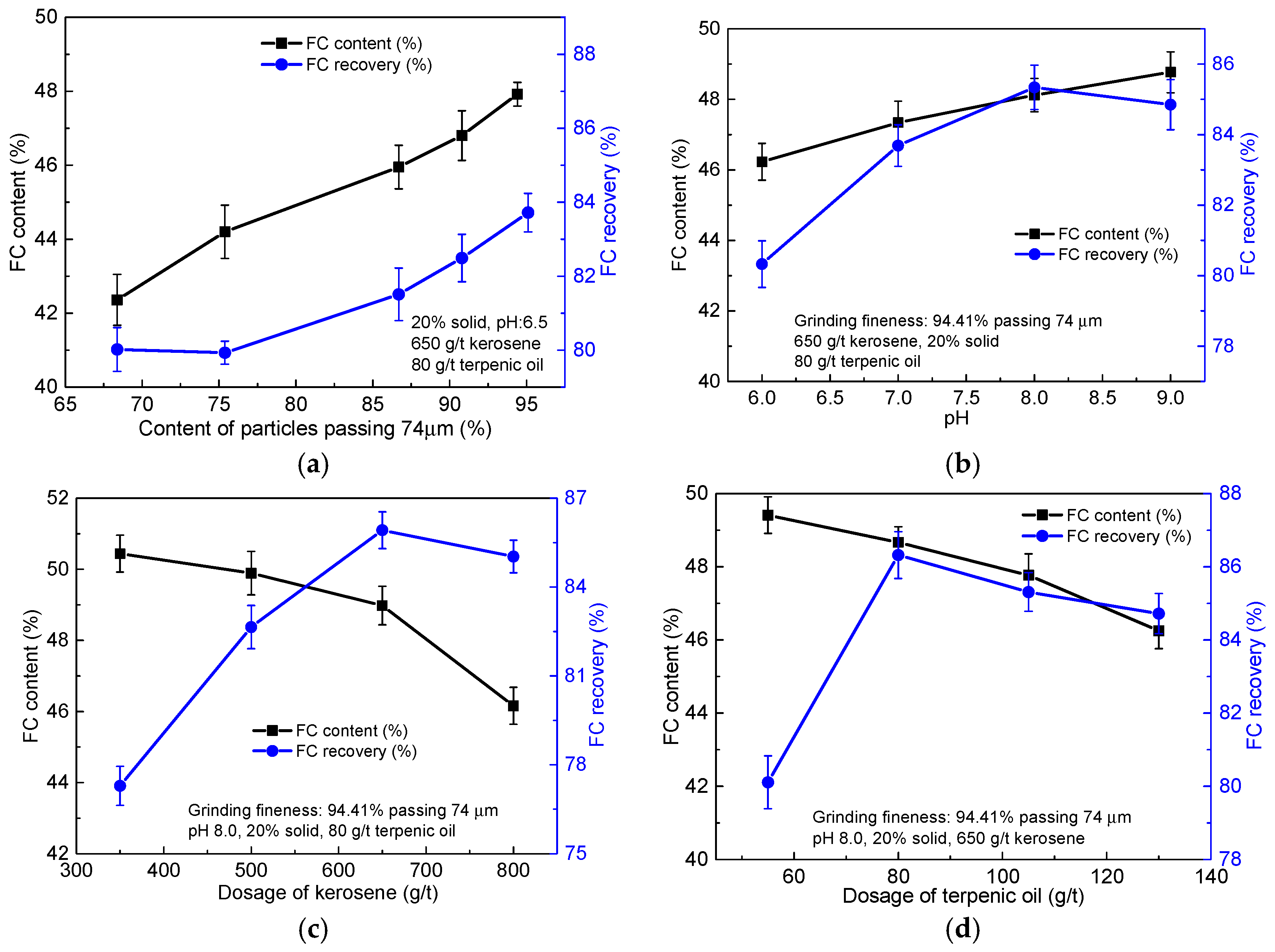
The rougher flotation tests of the raw ore were conducted as shown in Figure 4. Lime, kerosene and terpenic oil were added into the pulp one by one with an interval time of 3 min. The experimental parameters, such as grinding fineness of the raw ore, pulp pH, dosage of kerosene and terpenic oil were considered, and the relevant results are shown in Figure 5.
Grinding fineness greatly contributed to the individual liberation of the valuable mineral and gangue minerals, and then directly influenced the quality and recovery of the final concentrate [2,18]. Figure 5a shows that the FC content and recovery of the rougher concentrate increased with the content of particles passing 74 μm of the raw ore. When the −74 μm content of the raw ore reached 94.41%, the FC content and recovery of the rougher concentrate were 47.92% and 83.72%, respectively. Further increase the −74 μm content of the raw ore will surely consume more energy and reagent [19]. Therefore, the optimum grinding fineness of the raw ore was 94.41% passing 74 μm and applied for further flotation tests.
Pulp pH, considered to be one of the most important parameters of flotation, could directly affect the surface property of the mineral in the flotation system [14]. The effect of pulp pH on the FC content and recovery of the rougher concentrate are shown in Figure 5b. It can be seen from Figure 5b that the FC content of the rougher concentrate increased with the pulp pH, while the recovery first increased, and then decreased with further increasing the pulp pH. A maximum recovery (85.34%) was obtained at the pulp pH 8.0, which is in accordance with the precious report [20]. Therefore, it is appropriate to take pulp pH as 8.0 for continuing tests.
Although graphite holds high natural hydrophobicity, collector was also used to enhance the recovery in the flotation processing [14]. Figure 5c illustrates that the FC content of the rougher concentrate decreased from 50.44% to 46.16% with the dosage of kerosene increasing from 350 g/ton to 800 g/ton, while the recovery first increased and then reduced with the kerosene dosage. It may be due to that high concentration of kerosene lead to the selectively of the collector becomes poor. The maximum recovery (85.92%) was achieved when the dosage of kerosene was 650 g/ton. Hence, 650 g/ton kerosene concentration was chosen as suitable for further tests.
The dosage of terpenic oil also affected the FC content and recovery of the rougher concentrate, and results are shown in Figure 5d. The FC content and recovery of the rougher concentrate both first increased with the dosage of terpenic oil, and then decreased. Under the dosage of terpenic oil was 80 g/ton, the FC content (48.67%) and recovery (86.32%) of the rougher concentrate reached the maximum values. It is suggested that the terpenic oil concentration should be 80 g/ton for further flotation tests.
3.2. Open Circuit Test
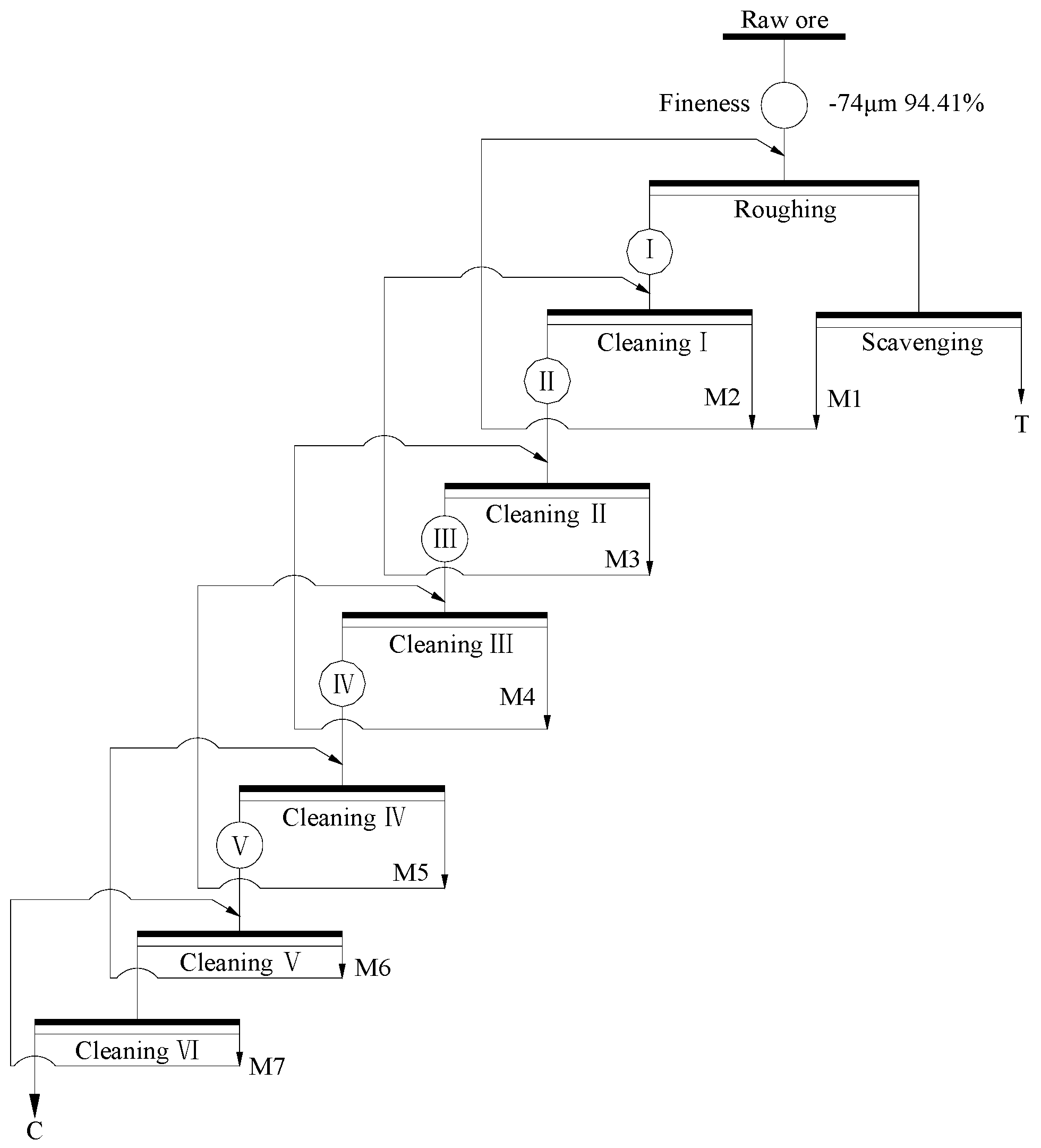
Based on the results of experimental parameters tests, an open circuit test of the raw ore was performed (as shown in Figure 6), and the pulp density and forth height of each flotation operation are summarized in Table 3. The results of the open circuit are shown in Table 4. As shown in Table 4, the raw ore via once coarse grinding and rougher flotation, and then the rougher concentrate re-grinded five times and refloated six times, the FC content and recovery of the final concentrate achieved to be 94.23% and 51.81%, respectively. The FC content of the final concentrate had a significant upgrade, while the recovery should be further enhanced.
3.3. Closed-Circuit Test
A closed-circuit test was conducted according to the above open-circuit test. The middlings were returned one by one as shown in Figure 7, and the results were summarized in Table 5. It can be seen that the FC content of the final concentrate decreased from 94.23% to 89.77% with the FC recovery increased from 51.81% to 79.48%. Moreover, the FC content of tailing reached 6.87%, and approximately 20.52% of the fine graphite was discarded. It may be due to that the fine intertexture of graphite and gangue minerals in the middlings cannot be well liberated with the used technological process. The fine intertexture was accumulated to tailing due to its poor floatability, and resulting in a great loss of graphite. Therefore, a suitable approach must be adopted to recover the fine graphite in the middlings as much as possible.
3.4. Middling Treatment Test
It can be seen from Table 4 that the total yield of M(1~4) reached up to be 40.35%, and the FC content of the merged M(1~4) mixture was 20.58%, less than that of the raw ore. Therefore, directly returning the merged M(1~4) mixture to the coarse grinding could not only increase the load of coarse grinding and rougher flotation, but also reduce the FC content of the feed ore of the rougher, resulting in a significant reduction of the FC content of the rougher concentrate. Therefore, an appropriate method must be adopted to deal with the middlings in order to increase the recovery of the fine flaky graphite.
Optical microscope was adopted to observe the merged M(1~4) mixture, and the obtained polarizing microscope images are shown in Figure 8. It can be observed from Figure 8 that the particle size of the merged M(1~4) mixture was very fine, and most particles were less than 30 μm. In addition, the residual graphite was wrapped by the gangue minerals, and most of the remained graphite particles were larger than that of the gangue minerals. Therefore, regrinding must be performed to make a further monomer liberation of the graphite and gangue minerals, and to efficiently recover the residual graphite.
Hence, the merged M(1~4) mixture was proposed to first regrinding and then scavenging (as shown in Figure 9), and the results are shown in Table 6. When the merged M(1~4) mixture was regrinded to 94.02% passing 45 μm, the FC content of M8 upgraded to be 57.36% with 31.64% recovery. The FC content of M8 was approximately 10% greater than that of the rougher concentrate, and less than that of the concentrate of the first cleaning. Therefore, directly returning M8 to the first regrinding could not only increase the FC content of the feed ore and the recovery of the final concentrate, but also make a further liberation of M8. Moreover, the FC content and losses of graphite of T2 were 3.98% and 4.35%, respectively, which could be directly discarded with T1.
Moreover, Table 4 also shows that the total yield of M(5~7) was 4.74%, and the FC content of the merged M(5~7) mixture was closed to that of the first cleaning concentrate. Furthermore, the polarizing microscope images of the merged M(5~7) mixture showed that there were many unsegregated gangue minerals adhered to the margin of graphite particles. For those reason, the merged M(5~7) mixture was considered to directly return to the second regrinding to obtain a further liberation before the third cleaning.
According to the morphology analysis and grinding-flotation test, a combined multiple treatment of middlings was proposed, consisting of the merged low FC content middlings (M1~4) via once regrinding-scavenging and the concentrate of scavenging (M8) directly return to the first regrinding, the middle FC content middlings (M5~7) return concentratedly to the second regrinding.
3.5. The Proposed Closed-Circuit Test
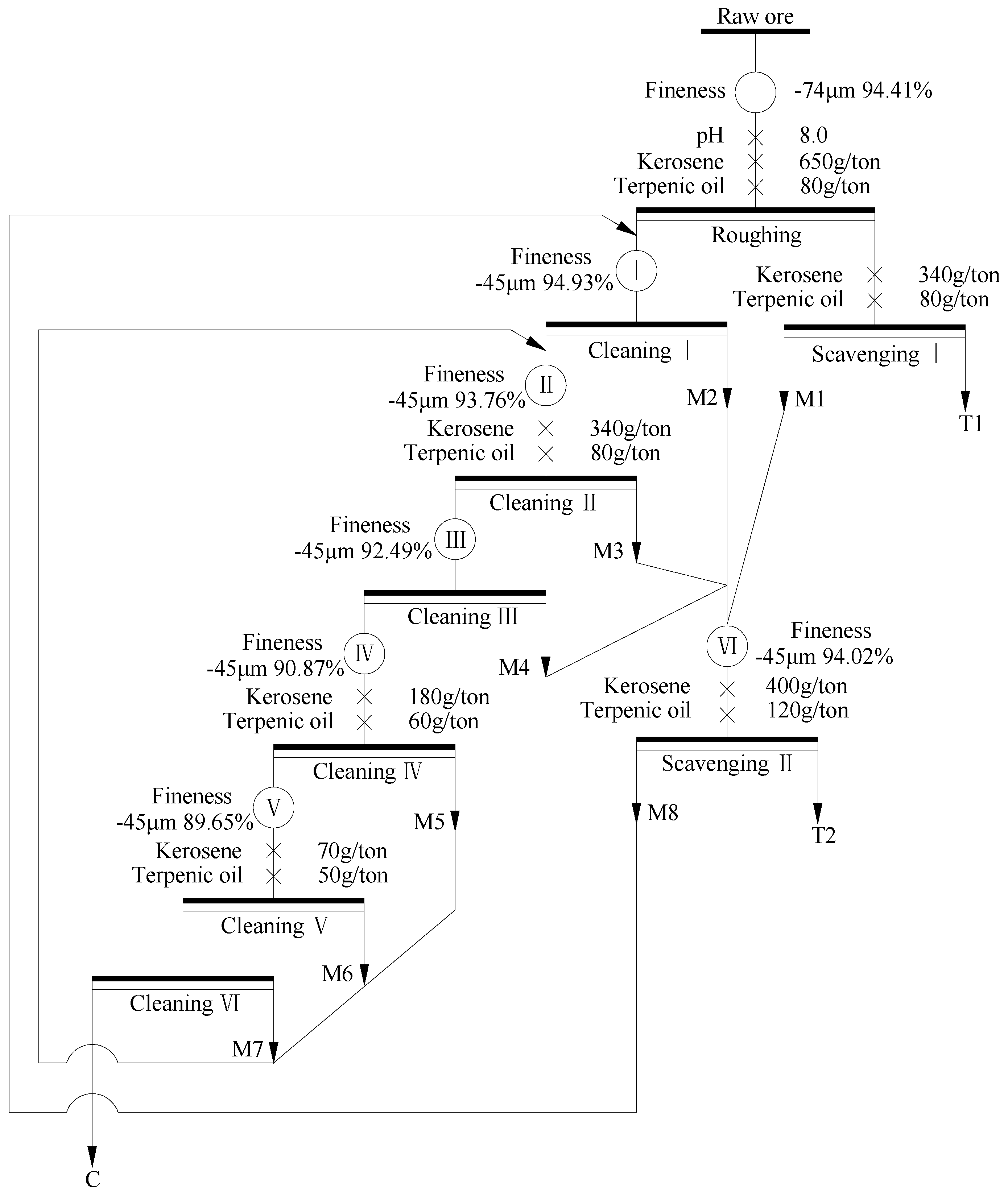
On the basis of the open-circuit test and proposed combined multiple treatment of middlings, 1.5 kg of the raw ore was used to perform the proposed closed-circuit test as shown in Figure 10, and the pulp density and forth height of each flotation operation are list in Table 7. The results of the proposed closed-circuit are shown in Table 8. The FC content of the final concentrate (C) was 92.01%, decreased a little, which may be attributed to the under-liberated interlocked graphite ore or the entrainment of superfine gangue minerals. Specifically, the yield of the final concentrate increased from 14.18% to 25.71%, and the recovery drastically increased to 91.14%. It indicated that the combination technique of individual processing and concentrated returning for the treatment of middlings had a significant improvement in the recovery of the fine flaky graphite ore via the multi-stage grinding-flotation technique.
4. Conclusions
In the work, a suitable strategy for the treatment of middlings was applied to enhance the recovery of the fine flaky graphite ore. The raw ore via once coarse grinding and roughing, and then the rougher concentrate regrinded five times and refloated six times, the final concentrate with 94.23% FC content and only 51.81% recovery was achieved. Optical microscope images indicated that most of the residual graphite particles in the middlings were still wrapped by the gangue minerals. Thus, the low FC content middlings (M1~4) merged and via once regrinding and scavenging, and the concentrate of scavenging (M8) directly return to the first regrinding. The middle FC content middlings (M5~7) return concentratedly to the second regrinding. The graphite recovery of the final concentrate upgraded to 91.14% at a FC content of 92.01%, indicating that the combination technique of individual processing and concentrated returning for the treatment of middlings could efficiently enhance the recovery of the fine flaky graphite ore.
Acknowledgments
The work is supported by the Development Fund for Outstanding Young Teachers of Zhengzhou University. Also, the financial supports for this work from the National Natural Science Foundation of China under the project No. 51504176, 51474167 and 51674183 are gratefully acknowledged.
Author Contributions
Weijun Peng conceived and designed the experiments, performed the experiments, and wrote the paper under the supervision of Lingyan Zhang and Shaoxian Song. Yangshuai Qiu and Junfang Guan revised the manuscripts and approved the manuscripts.
Conflicts of Interest
The authors declare no conflict of interest.
References
- Florena, F.F.; Syarifuddin, F.; Hanam, E.S.; Trisko, N.; Kustiyanto, E.; Enilisiana; Rianto, A.; Arinton, G. Floatability study of graphite ore from southeast Sulawesi (Indonesia). In AIP Conference Proceedings; American Institute of Physics: College Park, MD, USA, 2016; Volume 1712, No. 050005. [Google Scholar]
- Acharya, B.; Rao, D.; Prakash, S.; Reddy, P.; Biswal, S. Processing of low grade graphite ores of Orissa, India. Miner. Eng. 1996, 9, 1165–1169. [Google Scholar] [CrossRef]
- Mitchell, C. Industrial Minerals Laboratory Manual: Flake Graphite; British Geological Survey: Nottingham, UK, 1992. [Google Scholar]
- Zhang, X.; Zhang, L.Y.; Qiu, Y.S.; Qu, X. Beneficiation of a Low-Grade Flaky Graphite Ore from Australia by Flotation. In Advanced Materials Research; Trans Tech Publication: Zurich, Switzerland, 2015; pp. 188–192. [Google Scholar]
- Luke, L.; Chang, Y. Industrial Mineralogy: Materials, Processes, and Uses; Prentice Hall: Upper Saddle River, NJ, USA, 2002. [Google Scholar]
- Oney, O.; Samanli, S. Optimization of the Graphite Flotation Parameters Using a Central Composite Design, Optimization; IJETMAS: Delhi, India, 2016; Volume 4, pp. 15–16. [Google Scholar]
- Crossley, P. Graphite—High-tech supply sharpens up. Ind. Miner. 2000, 398, 31–47. [Google Scholar]
- Chelgani, S.C.; Rudolph, M.; Kratzsch, R.; Sandmann, D.; Gutzmer, J. A review of graphite beneficiation techniques. Miner. Process. Extr. Metall. Rev. 2016, 37, 58–68. [Google Scholar] [CrossRef]
- Nagaraj, D. Minerals Recovery and Processing, Kirk-Othmer Encyclopedia of Chemical Technology; John Wiley & Sons Inc.: Hoboken, NJ, USA, 2005. [Google Scholar]
- Weng, X.; Li, H.; Song, S.; Liu, Y. Reducing the Entrainment of Gangue Fines in Low Grade Microcrystalline Graphite Ore Flotation Using Multi-Stage Grinding-Flotation Process. Minerals 2017, 7, 38. [Google Scholar] [CrossRef]
- Andrews, P.R. The Beneficiation of Canadian Graphite Ores—A Review of Processing Studies at CANMET. CIM Bull. 1992, 85, 76–83. [Google Scholar]
- Mukherjee, S. Industrial Mineralogy: Mineral Processing, Beneficiations and Other Related Mineral Usage. In Appl. Mineral.; Springer: Berlin, Germany, 2011; pp. 428–489. [Google Scholar]
- Jianping, X.; Xin, Z.; Lingyan, Z. Experimental research on beneficiation of aphanitic graphite ore from Jilin area by flotation. China Non-Met. Miner. Ind. 2015, 5, 19–22. [Google Scholar]
- Wakamatsu, T.; Numata, Y. Flotation of graphite. Miner. Eng. 1991, 4, 975–982. [Google Scholar] [CrossRef]
- Zhang, L.; Huang, W.; Qiu, Y.; Pan, L.; Tu, W. Experimental Study on Purification of a Low-carbon Graphite Ore by Flotation. Wuhan Ligong Daxue Xuebao (J. Wuhan Univ. Technol.) 2011, 33, 107–111. [Google Scholar]
- Zhang, L.; Li, X.; Qiu, Y.; Guan, J.; Peng, W.; Qin, Y.; Jiang, F. Experimental Research on Beneficiation of a Refractory Graphite Ore from Sichuan. Jinshu Kuangshan/Met. Mine 2012, 7, 95–98. [Google Scholar]
- Qiu, Y.; Yu, Y.; Zhang, L.; Qian, Y.; Ouyang, Z. An Investigation of Reverse Flotation Separation of Sericite from Graphite by Using a Surfactant: MF. Minerals 2016, 6, 57. [Google Scholar] [CrossRef]
- Yu, X.-B.; Fang, H.-P.; Xiao, Y.-J.; Zhang, L.-Y. Experimental study on purification of a fine-scaled graphite ore by flotation. Conserv. Util. Miner. Resour. 2000, 1, 003. [Google Scholar]
- Qiming, F. Study on Wet Grinding Parameters for Producing Ultra-fine Graphite Particles. China Non-Met. Min. Ind. Her. 2003, 6, 005. [Google Scholar]
- Arbiter, N. Flotation. In SME Mineral Processing Handbook; Society of Mining Engineering: New York, NY, USA, 1985. [Google Scholar]
Figure 1.
(a) Typical multi-stage grinding-flotation technique for the flotation of graphite; (b) concentrated returning; (c) returning step-by-step; and (d) individual process techniques for the treatment of graphite middlings.
Figure 1.
(a) Typical multi-stage grinding-flotation technique for the flotation of graphite; (b) concentrated returning; (c) returning step-by-step; and (d) individual process techniques for the treatment of graphite middlings.
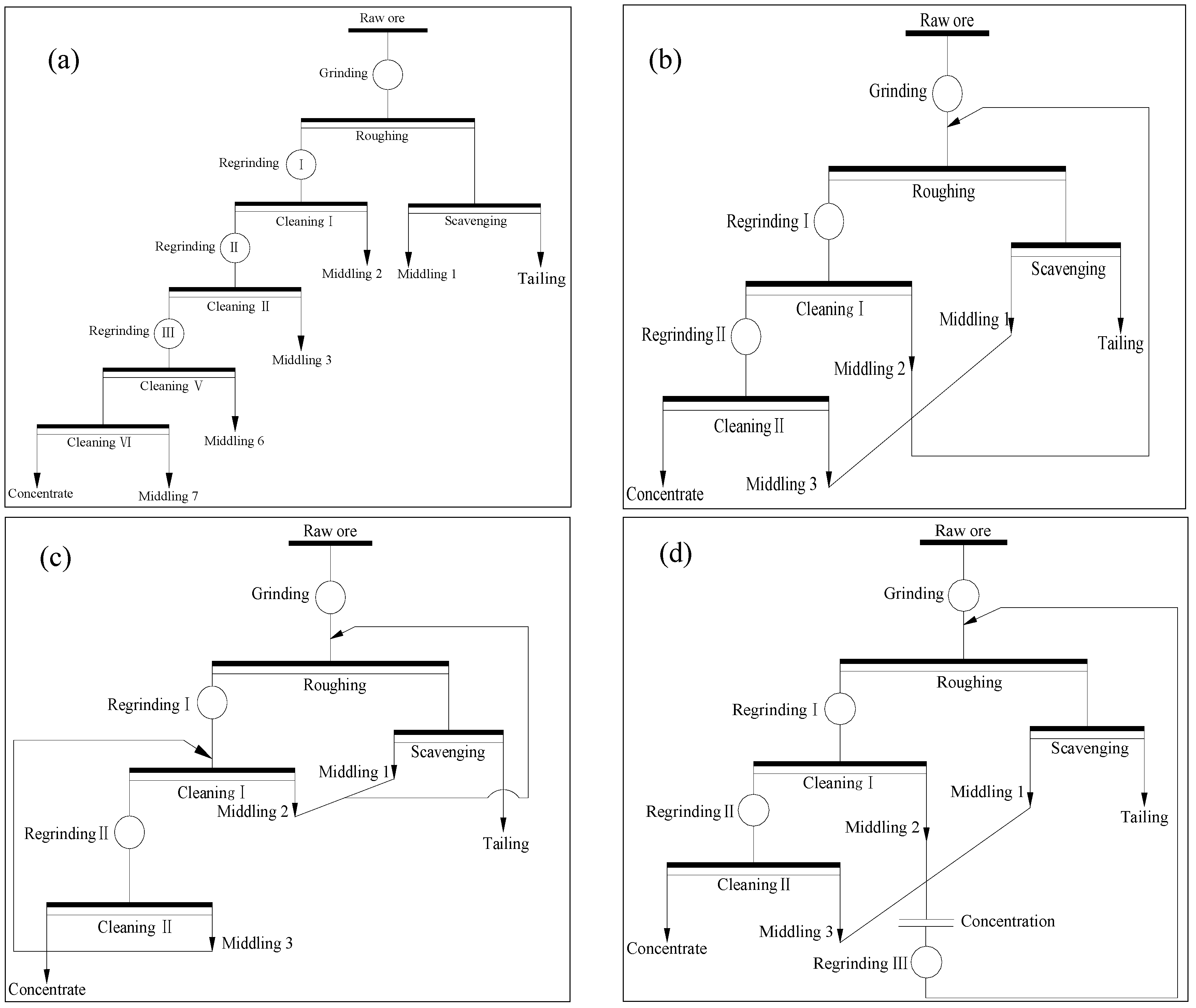
Figure 2.
XRD pattern of the raw ore.

Figure 3.
Polarizing microscope images of the raw ore: (a) directional distribution of graphite stripe; (b) fine intertexture of graphite and gangue minerals (the black is graphite, and the others are gangue minerals).
Figure 3.
Polarizing microscope images of the raw ore: (a) directional distribution of graphite stripe; (b) fine intertexture of graphite and gangue minerals (the black is graphite, and the others are gangue minerals).

Figure 4.
Flow chart of rougher flotation for experimental parameters.

Figure 5.
(a) Experimental parameters of rougher flotation tests; (b) grinding fineness of the raw ore; (c) pulp pH, and dosage of kerosene; and (d) terpenic oil.
Figure 5.
(a) Experimental parameters of rougher flotation tests; (b) grinding fineness of the raw ore; (c) pulp pH, and dosage of kerosene; and (d) terpenic oil.

Figure 6.
Flow chart of open circuit test.
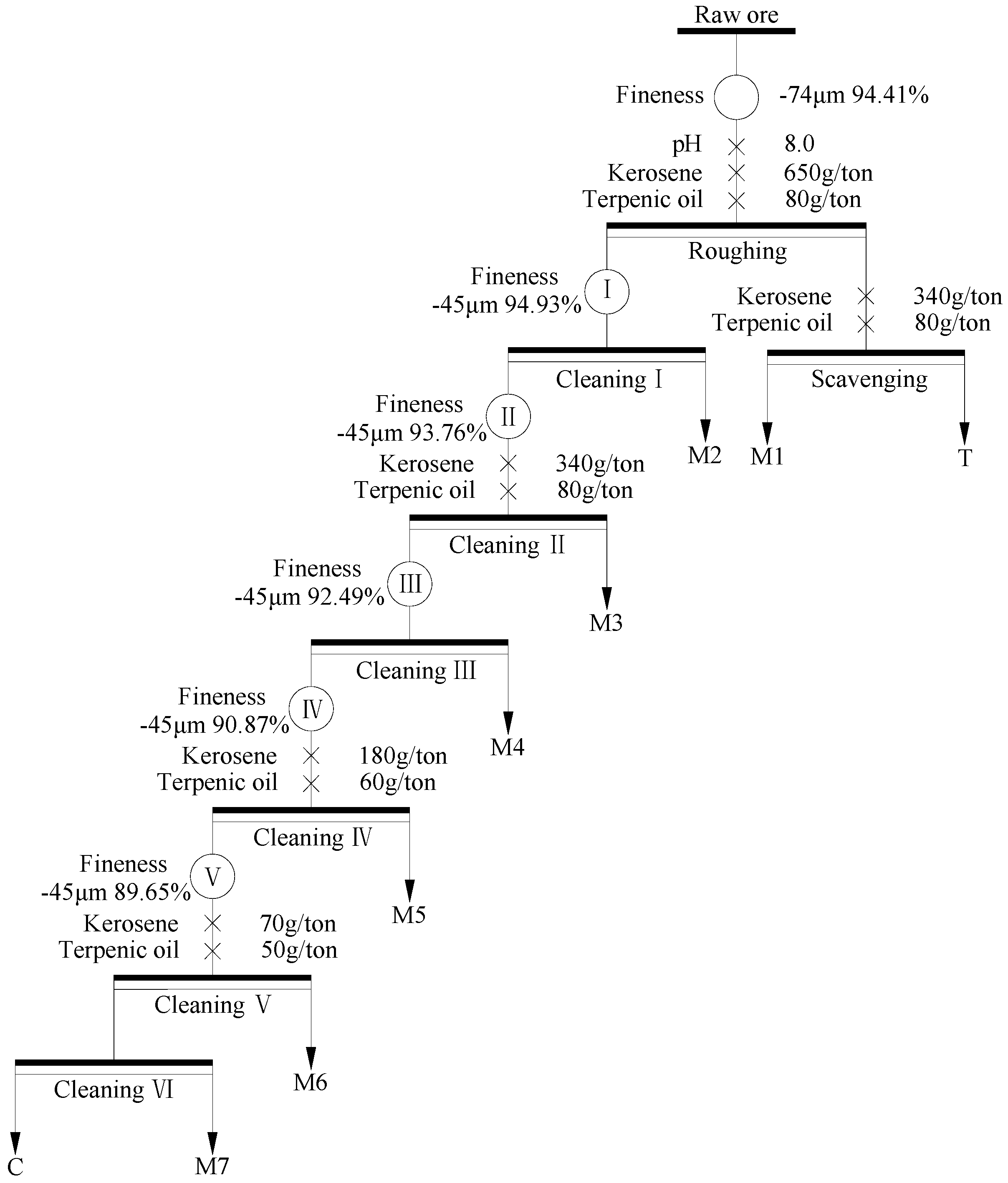
Figure 7.
Flow chart of closed-circuit test.

Figure 8.
Polarizing microscope images of the merged M(1~4) mixture (the black is graphite, and the others are gangue minerals).
Figure 8.
Polarizing microscope images of the merged M(1~4) mixture (the black is graphite, and the others are gangue minerals).
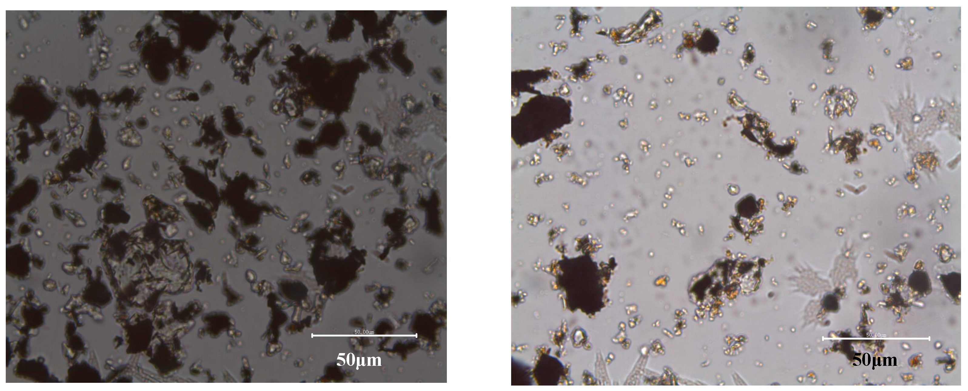
Figure 9.
Flow chart of the treatment of middling (1~4) with low FC content.
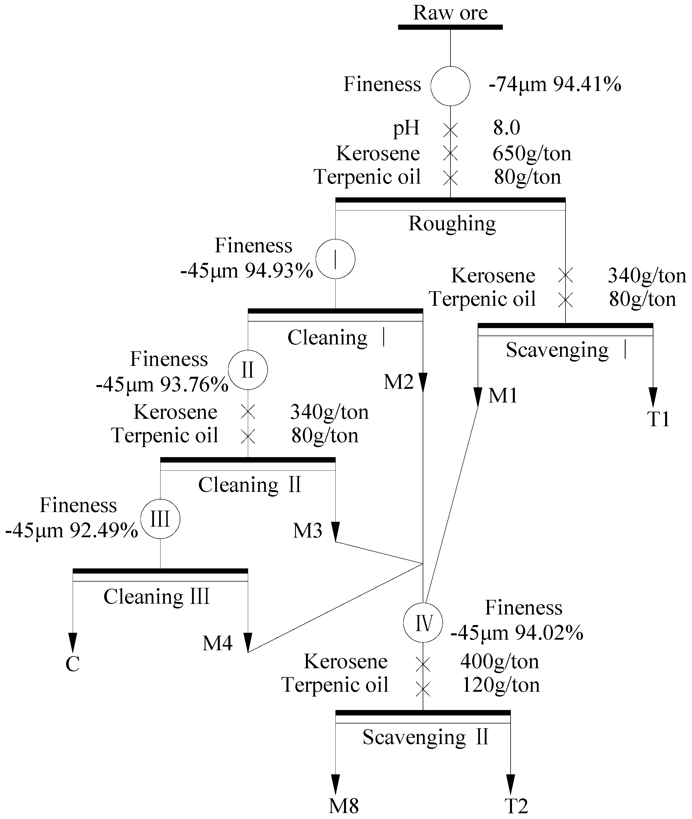
Figure 10.
Flow chart of the close circuit test.

Table 1.
Chemical compositions analysis of the raw ore (wt %).
| Composition | SiO2 | Al2O3 | TFe2O3 | MgO | CaO | Na2O | K2O |
| Content, % | 47.85 | 8.17 | 4.84 | 2.26 | 2.59 | 1.87 | 2.46 |
| Composition | TiO2 | P2O5 | MnO | H2O | SO3 | loss | FC |
| Content, % | 0.54 | 0.28 | 0.034 | 0.13 | 2.04 | 28.43 | 25.95 |
Table 2.
Mineral compositions of the raw ore (wt %).
| Species | Feldspar | Graphite | Quartz | Mica | Tremolite | Chlorite | Phosphorite | Others |
|---|---|---|---|---|---|---|---|---|
| Content % | 28 | 25 | 25 | 10 | 6 | 2 | 2 | 3 |
Table 3.
Pulp density and forth height of each flotation operation in open circuit.
| Flotation Parameters | Roughing | Cleanning I | Cleanning II | Cleanning III | Cleanning IV | Cleanning V | Cleanning VI | Scavenging |
|---|---|---|---|---|---|---|---|---|
| Pulp density (wt %) | 20 | 10.55 | 6.89 | 5.41 | 4.52 | 4.06 | 3.70 | 11.67 |
| Forth height (mm) | 19 | 24 | 26 | 26 | 25 | 26 | 25 | 13 |
Table 4.
Result of open circuit test.
| Products | Yield % | FC % | Recovery % |
|---|---|---|---|
| Concentrate | 14.18 | 94.23 | 51.81 |
| M1 | 12.11 | 24.14 | 11.45 |
| M2 | 17.54 | 13.15 | 9.03 |
| M3 | 6.75 | 19.08 | 5.04 |
| M4 | 3.95 | 45.23 | 7.00 |
| M5 | 2.00 | 50.77 | 3.97 |
| M6 | 1.56 | 63.11 | 3.86 |
| M7 | 1.18 | 79.72 | 3.67 |
| T | 40.73 | 2.45 | 3.91 |
| Raw ore | 100.00 | 25.54 | 100.00 |
Table 5.
Result of closed-circuit test.
| Products | Yield % | FC % | Recovery % |
|---|---|---|---|
| Concentrate | 22.87 | 89.77 | 79.48 |
| T | 77.13 | 6.87 | 20.52 |
| Raw ore | 100.00 | 25.83 | 100.00 |
Table 6.
Results of the treatment of middling (1~4) with low FC content.
| Product | Yield/% | FC/% | Recovery/% |
|---|---|---|---|
| Concentrate | 17.86 | 86.52 | 60.36 |
| M8 | 14.12 | 57.36 | 31.64 |
| T1 | 40.05 | 2.34 | 3.66 |
| T2 | 27.97 | 3.98 | 4.35 |
| Raw ore | 100.00 | 25.60 | 100.00 |
Table 7.
Pulp density and forth height of each flotation operation in the proposed closed-circuit.
| Flotation Parameters | Roughing | Cleanning I | Cleanning II | Cleanning III | Cleanning IV | Cleanning V | Cleanning VI | Scavenging I | Scavenging II |
|---|---|---|---|---|---|---|---|---|---|
| Pulp density (wt %) | 20 | 17.54 | 11.90 | 10.18 | 9.15 | 7.70 | 6.57 | 12.27 | 11.47 |
| Forth height (mm) | 19 | 26 | 29 | 31 | 29 | 30 | 28 | 14 | 18 |
Table 8.
Results of the closed-circuit test.
| Product | Yield % | FC % | Recovery % |
|---|---|---|---|
| Concentrate | 25.71 | 92.01 | 91.14 |
| T1 | 40.05 | 2.26 | 3.49 |
| T2 | 34.24 | 4.07 | 5.37 |
| Raw ore | 100.00 | 25.95 | 100.00 |
© 2017 by the authors. Licensee MDPI, Basel, Switzerland. This article is an open access article distributed under the terms and conditions of the Creative Commons Attribution (CC BY) license (http://creativecommons.org/licenses/by/4.0/).
Share and Cite
MDPI and ACS Style
Peng, W.; Qiu, Y.; Zhang, L.; Guan, J.; Song, S. Increasing the Fine Flaky Graphite Recovery in Flotation via a Combined MultipleTreatments Technique of Middlings. Minerals 2017, 7, 208. https://doi.org/10.3390/min7110208
AMA Style
Peng W, Qiu Y, Zhang L, Guan J, Song S. Increasing the Fine Flaky Graphite Recovery in Flotation via a Combined MultipleTreatments Technique of Middlings. Minerals. 2017; 7(11):208. https://doi.org/10.3390/min7110208
Chicago/Turabian StylePeng, Weijun, Yangshuai Qiu, Lingyan Zhang, Junfang Guan, and Shaoxian Song. 2017. "Increasing the Fine Flaky Graphite Recovery in Flotation via a Combined MultipleTreatments Technique of Middlings" Minerals 7, no. 11: 208. https://doi.org/10.3390/min7110208
Note that from the first issue of 2016, this journal uses article numbers instead of page numbers. See further details here.