
Feasibility of Recycling Ultrafine Leaching Residue by Backfill: Experimental and CFD Approaches


1
School of Resources and Safety Engineering, Central South University, Changsha 410083, China
2
School of Civil, Environmental and Mining Engineering, The University of Western Australia, Crawley 36009, Australia
*
Authors to whom correspondence should be addressed.
Minerals 2017, 7(4), 54; https://doi.org/10.3390/min7040054
Submission received: 3 March 2017
/
Revised: 24 March 2017
/
Accepted: 2 April 2017
/
Published: 5 April 2017
(This article belongs to the Special Issue Minerals in Mine Wastes: Contributions to the Circular Economy)
Abstract
:Large amounts of leaching residue are released into tailings dams from mines, and their acid content can cause environmental pollution. The aim of this study was to research the feasibility and value of a leaching residue backfill recycling method. The combination of property detection, laboratory tests (the neutralization method, strength test and diffusivity test) and numerical simulation methods (3D computational fluid dynamics (CFD) simulations of pipeline transportation properties) were used to assess the performance of the leaching residue backfill. The results show that backfill body with the cement:sand mass ratio of 1:3, the leaching residue:classified tailings ratio of 1:6, and slurry mass concentration of 71 wt % can meet the strength and pipeline self-flowing transportation requirements of mine backfill. The leaching residue is a good backfill aggregate, and its recovery ratio can reach 19.5 wt %. In addition, the recycling of leaching residue effectively alleviates the problem of mine waste emissions and protects the ecological environment surrounding the mining area. This study serves as a guide for the recycling of fine tailings and the environmental governance of the mining area.
1. Introduction
The processing and management of mine tailings has been receiving more and more attention around the world [1,2]. As the main solid waste of mines, most of the tailings are stored in tailings dams and are hard to recycled. Many large tailings dams have to be built to contain mining waste [3,4]. However, they are often accompanied by many types of hazards, and the harm of waste tailings to the environment, the safety of lives and property is very significant [5,6,7,8]. In order to address those issues that mine tailings entail, some mining researchers proposed the backfill method to improve the recovery of the tailings. Furthermore, the paste backfill technology has been widely used all over the world for mine tailings treatment [9,10]. As pointed out by Edraki et al. [11] and Benzaazoua et al. [12], the mine backfill is an effective method to dispose of the tailings.
The Fan Kou lead–zinc mine, located in the northeastern Guangdong Province of China, outputs 1.4 million tons of ore per year. Also, more and more advanced technologies are used to increase the extraction rate of minerals by grinding the crushed ore into finer and finer particles. This leads to 26,000 tons of super fine leaching residue that are piled into the tailings dam every year. It is well known that the ultrafine tailings will reduce the mass concentration of backfill slurry significantly, and the strength of backfill will also decline correspondingly, which makes it impossible to uses ultrafine tailings as a backfill aggregate separately [13]. However, on the other side, the ultrafine particles have been proven to be of benefit to the transportation of the backfill slurry [14]. Combined with that, there is a large amount of classified tailings in this mine that will harm the pipeline due to its coarse particles when utilized as a backfill aggregate. Thus, the question is raised: what if utilizing a mixture of ultrafine leaching residue and coarse classified tailings as an aggregate? To test this idea, it is necessary to research the backfill characteristics with different mixing ratios of the two materials. As we know, in industrial production, the strength of backfill and the fluidity of backfill slurry are both key factors affecting the efficient recycling of tailings [15]. Without the optimized mixing ratio, the inevitable sedimentation and segregation in backfill will lead to the coarse particles gathering at the bottom of a stope and the fine particles gathering at the top with water, i.e., low strength [16]. What is more, backfill technology is generally utilized in pipeline transportation, therefore transportability is also a key factor that affects the choice of mixing ratio [17]. There is a series of technical problems in deep mining, with the problem of backfill pipeline transportation being a significant one [18]. For this mine, the common fluidity experiments in the laboratory, such as slump tests, diffusivity and the looping pipe experiment, however, cannot fully reflect the flow state and the pipeline resistance. The computational fluid dynamics (CFD) technology is applied to study the pressure and velocity of slurry transport by building a pipeline transportation model [19,20,21]. Thus, it is also a reliable way to illustrate the details of slurry transport resistance and flow state.
Therefore, in this study, a series of scientific research methods was used to find the suitable backfill method to recycle leaching residues effectively. The recycling of leaching residue can not only bring huge economic benefits, but also protect the environment of the mining area.
2. Materials and Methods
2.1. Physicochemical Properties
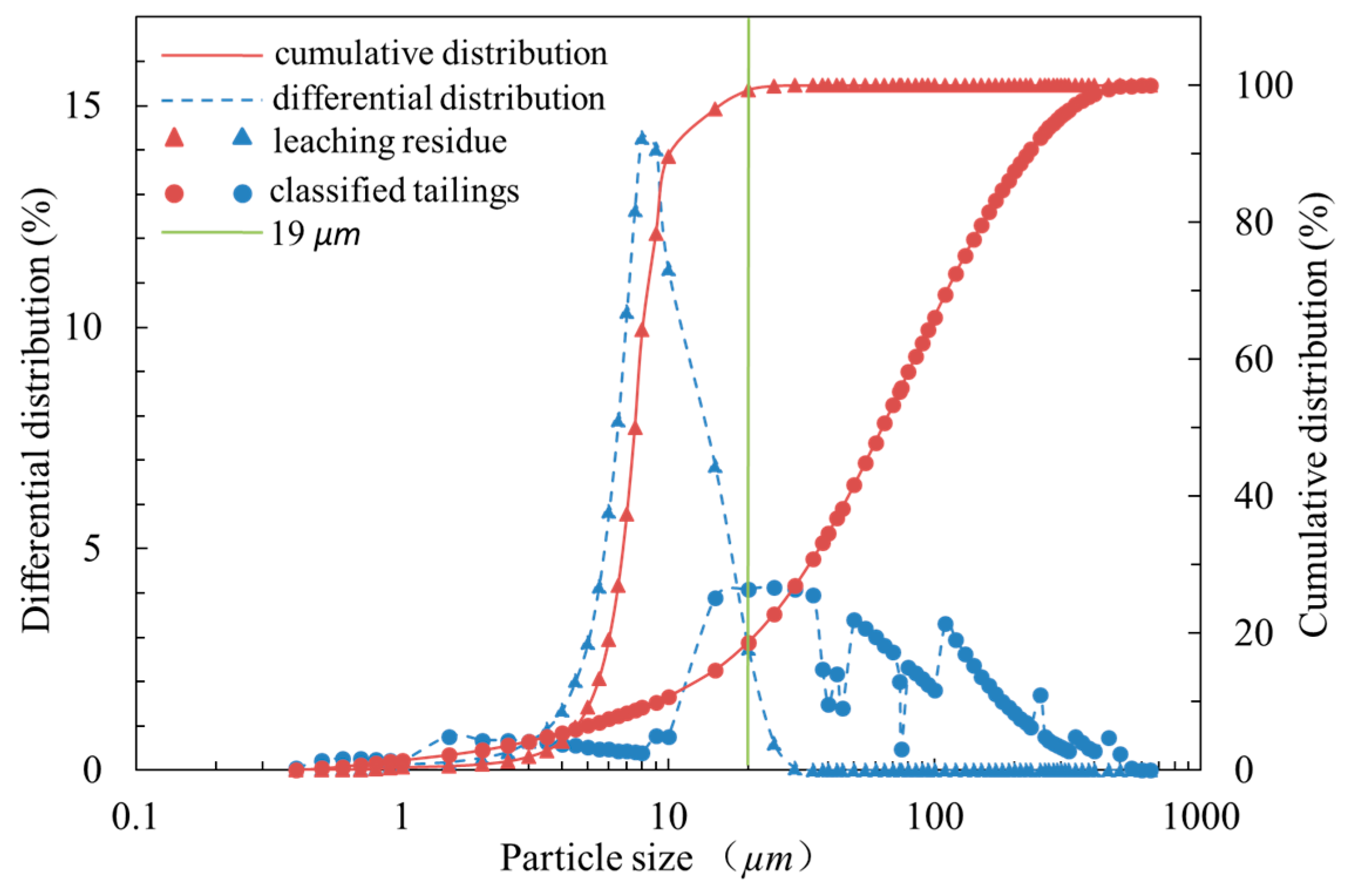
The applied research measured the leaching residue size and classified tailings size using a laser granulometer (S3500, Microtrac, FL, USA), and the results are shown in Figure 1. Figure 1 shows that the leaching residue in the Fan Kou mine is ultrafine with proportions of more than 99 wt % for particles less than 19 µm in diameter. An excess of ultrafine particles makes the slurry become a paste at lower mass concentrations, which cannot meet the high mass concentration transport requirements [22,23,24]. The physical properties and the chemical composition of the leaching residue and classified tailings are listed in Table 1 and Table 2. The non-uniform coefficient of the leaching residue is less than 5, which indicates that it has poor gradation. In addition, the leaching residue backfill body cannot be dehydrated over time, and the strength is not sufficient due to the low permeability. Therefore, the leaching residue cannot be used as a backfill aggregate alone, and it must be used in conjunction with the classified tailings. Table 2 shows that the SiO2 content in the leaching residue is as high as 84.08 wt %, indicating that the leaching residue is a good backfill aggregate.
Table 1 shows that leaching residue is strongly acidic (pH = 3.29–3.79). Because it is easy for acid tailings to cause widespread land contamination and river pollution and because acid slurries can cause corrosion of the backfill pipe [25], the neutralization treatment of leaching residues should be carried out first to keep the backfill slurry weakly alkaline. The essence of the neutralization reaction is a process of hydrogen ion (H+) and hydroxyl ion (OH−) combination to form water (H2O) [26]. Table 3 shows that the extraction toxicity of the leaching residue is within the identification standards for the hazardous wastes of China. Therefore, we just need to address the acidity of the leached residue.
2.2. Strength Test
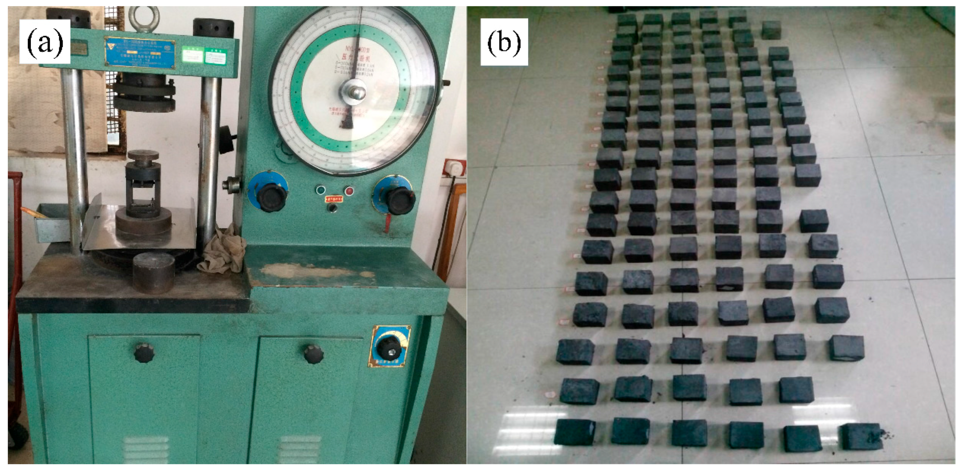
The strength of the backfill is an important factor to ensure the safe working conditions of stopes [16]. The orthogonal test is a method for designing a study to determine the influences of multiple factors and multiple levels [28]. Therefore, in this work, the orthogonal test was chosen to study the compressive strength of the backfill body. The three factors are (A) the cement:sand mass ratio; (B) the leaching residue:classified tailings mass ratio; (C) and the slurry mass concentration. Every factor has four levels, and they are as follows: 1:3 (A1), 1:4 (A2), 1:5 (A3) and 1:6 (A4); 1:4 (B1), 1:5 (B2), 1:6 (B3) and 1:7 (B4); and 67 wt % (C1), 69 wt % (C2), 71 wt % (C3), and 73 wt % (C4). According to the principles of the orthogonal test, the orthogonal table of L16 (43) was chosen to implement the backfill test. The backfill test specimens were made using a 7.07 cm × 7.07 cm × 7.07 cm standard triple test mold and cured in a standard curing box with a temperature of 21 °C and a humidity of 81%. Finally, as shown in Figure 2, the compressive strengths at 3 days, 7 days and 28 days were measured using a WDW-2000 rigid hydraulic pressure servo machine (Ruite, Guilin, China).
2.3. Rheological Properties
2.3.1. Diffusivity
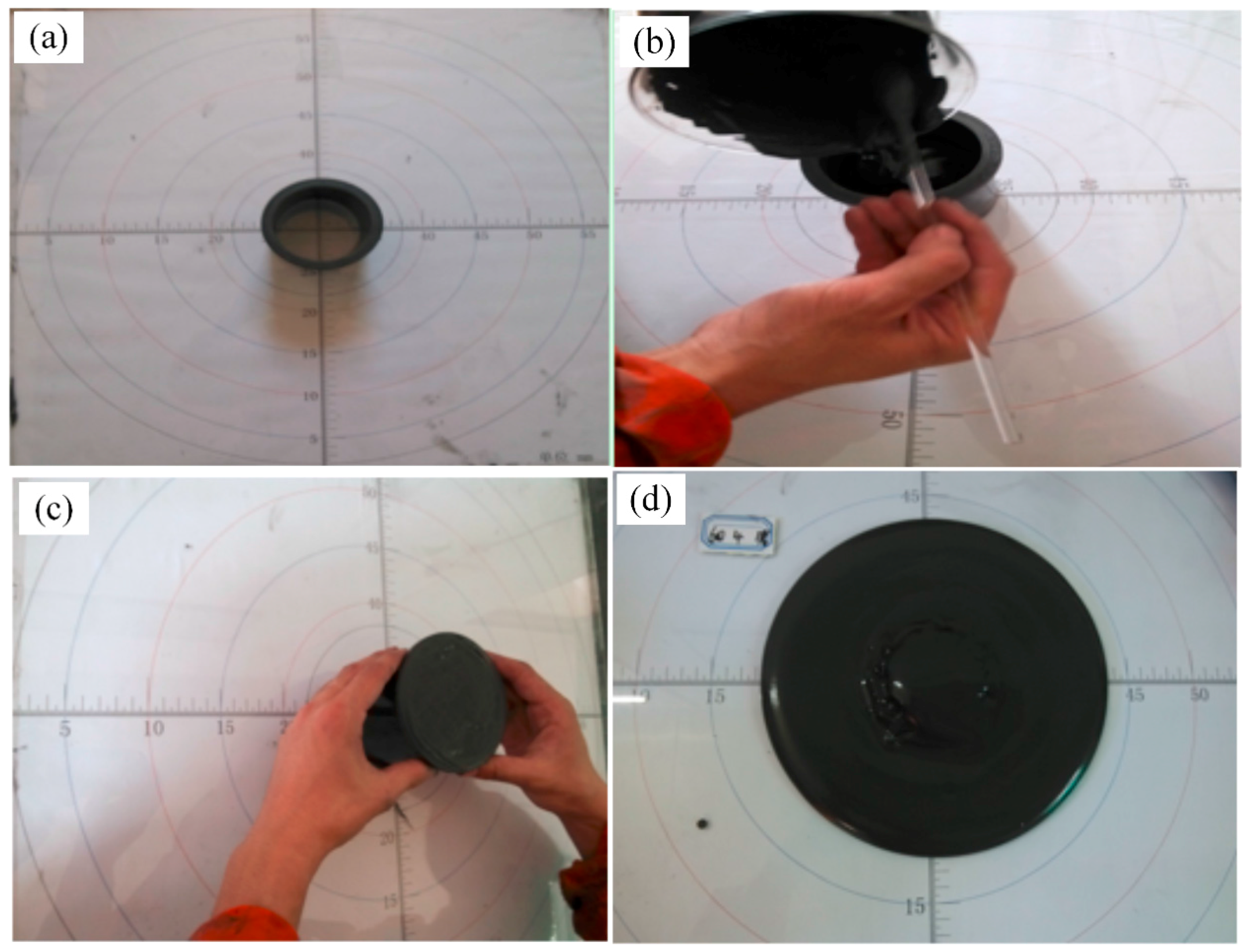
The backfill slurry must be transported to the stope under the force of gravity or by pumping. Diffusivity tests were used to measure the fluidity of flowing concrete by the resulting dispersion area from the natural accumulation. Diffusion degree is used as a quantitative index to characterize the fluidity of the slurry; the greater the dispersion area, the better the fluidity of the slurry. The experiments were carried out using a self-designed device, which included a cylinder that was 8 cm high with an upper and lower diameter of 8 cm. Figure 3 shows the experimental method.
2.3.2. CFD Simulations of Pipeline Transportation
Finally, the recovery and utilization of the leaching residue are achieved through pipeline transportation. Therefore, research into the resistance of pipe flow with different pipe diameters, slurry mass concentrations and transportation velocities is very important. As shown in Figure 4, a three-dimensional model was developed for a typical L-shaped backfill pipeline for long-distance transportation, which is used here to study the transport properties of the backfill slurry. The pipe was made of a seamless steel pipe, and its detailed geometrical parameters include a 200 m vertical pipe height, a 500 m horizontal pipe length, a 150 mm inner pipe diameter, a 168 mm outer pipe diameter (with a 9 mm pipe wall thickness), a 90° elbow angle and a 1 m elbow radius. In addition, its backfill ability is 80 m3/h.
The leaching residue slurry is a paste slurry material because of its high mass fraction, low water content and good integrity. In the present work, the flow of the slurry was modeled as a Bingham fluid [29]. The shear stress model for a Bingham fluid is:
where τ is the shear stress (Pa), τ0 is the yield stress (Pa), µ is the plastic viscosity (Pa·s), and is the shear rate (1/s).
The slurry enters the backfill pipe under the action of gravity and flows through the backfill pipe. The steady conservation equations for continuous momentum and pressure are expressed as follows [30]:
where t is the time, ρ is the density of the slurry, v is the velocity of the slurry, X, Y and Z are the surface forces in the different directions, F is the force on the fluid element, Fi is the pressure at the corresponding position, g is the gravitational acceleration, and hf is the resistance from z1 to z2.
The effects of heat exchange, vibration, stress waves and compression were not considered in the simulations. The applicable boundary conditions were as follows [31,32]:
- (1)
- At the walls, the standard wall function was used in all pipe segments.
- (2)
- At the pipe inlet, the velocity (v) function given below was used at the inlet face.
- (3)
- At the pipe outlet, the outflow function was used at the outlet face.
The governing equations together with the computational model and boundary conditions were solved using the finite volume CFD code Fluent 14.5 [30]. The equations were solved with the Semi-Implicit Pressure-Linked Equation (SIMPLE) algorithm, using second-order upwind discretization.
3. Results and Discussion
3.1. Neutralization Method
Because the leaching residue contains hydrochloric acid (HCl), the backfill slurry prepared by the leaching residue is acidic. Therefore, slaked lime [Ca(OH)2] was used to neutralize the acidity. A mass of 100 g of the leaching residue was used to prepare a leached residue solution mass concentration of 13.2 wt %. Ca(OH)2 was added until the measured pH value was greater than 7. Acid-base titration was performed to ensure that the backfill slurry was weakly alkaline. The mass concentration of the leaching residue solution was maintained at 13.2 wt %, and Ca(OH)2 was added until the solution pH reached 9.76. After repeated experiments using 100 g of leaching residue, the usage of Ca(OH)2 was 1 g. The weakly alkaline backfill slurry can avoid pipeline corrosion and pollution of the underground environment. Figure 5 shows the experimental.
3.2. Variance Analysis
The results and the orthogonal table are shown in Table 4. SPSS software [33,34] was used to analyze the variance of the strength test and diffusivity test results, and the analysis results are shown in Table 5. When the significance level is greater than 0.05, the influence of the factors is not significant.
3.2.1. Strength Analysis
Table 5 shows that factor B has no significant effect on the strength of the backfill specimens, and the significance order is B = C > A. This means that the effect of the slurry mass concentration on the backfill body strength is the largest, followed by the cement:sand mass ratio and then the influence of the leaching residue:classified tailings mass ratio.
The average compressive strength values corresponding to each level are shown in Figure 6. Figure 6 shows that the strength of the backfill specimens increased with both the cement:sand mass ratio and slurry mass concentration. However, the strength effect with the leaching residue:classified tailings mass ratio has a minimum value at B2 (1:5). This indicates that from B2 (1:5) to B1 (1:4), the increase in the leaching residue causes many fine aggregates to fill the gaps between the coarse aggregates, increasing the strength of the backfill body. However, from B4 (1:7) to B2 (1:5), the increase in the fine aggregates is not sufficient to make up for the influence of the coarse aggregates on the strength of the backfill body, so the strength decreases.
3.2.2. Diffusivity Analysis
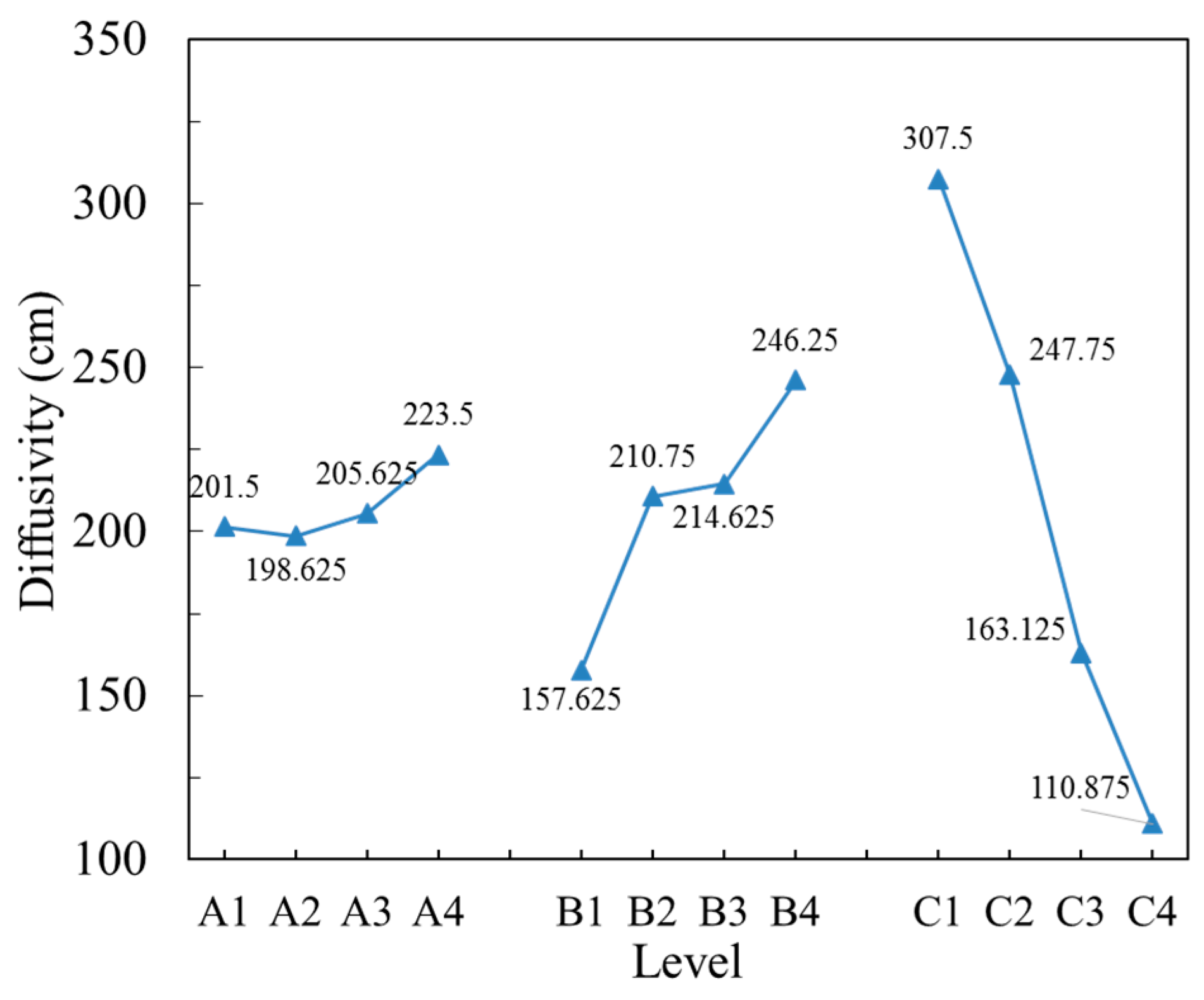
Table 5 shows that the factor A has no significant effect on the diffusivity of the backfill slurry, and the significance order is C > A > B. This means that the effect of the slurry mass concentration and the leaching residue:classified tailings ratio on the backfill slurry diffusivity is larger than that of the cement:sand mass ratio.
The average diffusivity values corresponding to each level are shown in Figure 7. Figure 7 shows that the diffusivity increases as the leaching residue:classified tailings mass ratio decreases, but it decreases as the leaching residue:classified tailings mass ratio increases. The reason for this is that the leaching residue is made of ultrafine tailings, and its high viscosity can easily increase the flow resistance. In addition to slurry compositions at low mass concentrations, it is easy to form a paste with a large number of fine tailings, and it can cause the viscosity of the slurry to increase and show poor fluidity. Therefore, we consider the leaching residue:classified tailings mass ratios of 1:5–1:7 (B2 and B3) and slurry mass concentrations of 69 wt %–71 wt % (C2 and C3) as the range for achieving good diffusivity.
3.2.3. Proportioning Scheme
To meet the safety requirements for production, the strength of the backfill body is as follows:
- (1)
- room stopes: the cement:sand mass ratio is 1:6~1:8; 28 days compressive strength is greater than 4 MPa;
- (2)
- pillar stopes: the cement:sand mass ratio is above 1:12; 28 days compressive strength is 2–3 MPa;
- (3)
- artificial bottom, casting surface and first backfill layer: the cement:sand mass ratio is 1:3–1:4; 3 days compressive strength is greater than 1.5 MPa, and 28 days compressive strength is greater than 5 MPa.
Based on the test results and strength requirements, the proportioning scheme includes the cement:sand mass ratio of 1:3, the leaching residue:classified tailings mass ratios of 1:4, 1:6 and 1:7, and a slurry mass concentration of 71 wt % and 73 wt %. Regarding alignment of the required strength and diffusivity (with the leaching residue:classified tailings mass ratio 1:5–1:7 and slurry mass concentration 69 wt %–71 wt %), the proportioning scheme includes the cement:sand mass ratio of 1:3, the leaching residue:classified tailings mass ratios of 1:6 and 1:7, and slurry mass concentration of 71 wt %.
3.3. Pipeline Transportation Properties
3.3.1. Pressure
Preparation of the slurry using the proportioning scheme that we chose (the cement:sand mass ratio of 1:3, the leaching residue:classified tailings mass ratios of 1:6 and 1:7, and slurry mass concentration of 71 wt %), and the results of the pressure tests, are shown in Table 6. To achieve the self-flowing transport of a backfill material through a pipeline, the gravitational potential energy must be greater than the resistance loss of the pipeline, which is defined as the total pressure difference between the inlet and outlet of the pipeline. The equations for the gravitational potential energy and resistance loss are as follows [35]:
where p is the gravitational potential energy (Pa), g is the gravitational acceleration (i.e., 9.8 m/s2), h is the height difference (m), hf is the resistance loss (Pa), py is the total pressure difference (Pa), pin is the total pressure at the inlet (Pa), and pout is the total pressure at the outlet (Pa).
As shown in Table 6, the resistance values of case 1 and case 2 are smaller than the gravitational potential energy, and both meet the requirements for self-flowing transportation. Thus, the backfill slurry can be carried to the stopes properly; eliminating the use of the pump will greatly decrease the cost of backfill.
3.3.2. Velocity
Controlling the transport velocity of the slurry is also an important factor in pipeline transport [36]. The speed needs to be maintained within a suitable range to prevent the solid particles from settling or the pipe wall from wearing. The velocities of the slurry at the elbow for different cases are shown in Figure 8. As shown in Figure 8, the flow core zone gradually becomes smaller and moves from the center of the pipe to the exterior of the elbow, and the flow state of the slurry fluctuates. The maximum velocities for the different leaching residue:classified tailings mass ratios of 1:6 and 1:7 are 2.69 m/s and 2.72 m/s, respectively.
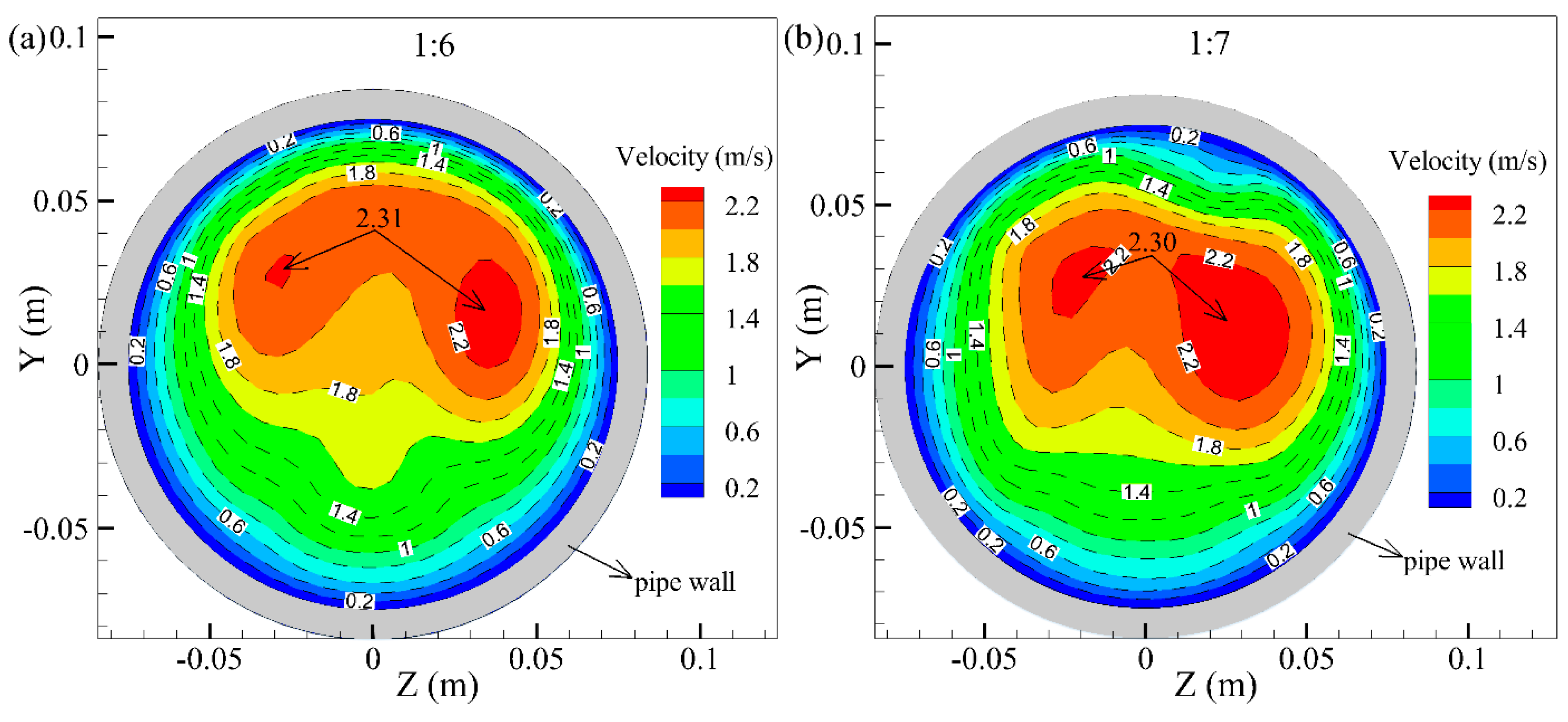
Figure 9 shows the velocity distribution at the outlet of the pipe with different leaching residue:classified tailings mass ratios. As shown in Figure 9, the velocity distribution has areas of localized enlargement, and the high velocity areas are still concentrated in the center of the pipe. The maximum velocities for the different leaching residue:classified tailings mass ratios of 1:6 and 1:7 are 2.30 m/s and 2.31 m/s, respectively.
The velocity variation trend shows an increase in the vertical pipe and a decrease in the horizontal pipe; the maximum velocity occurs at the elbow of the pipe. The mine backfill experience of South Africa indicated that the velocity of the horizontal pipe should not exceed 4 m/s [19]. Therefore, the two proportioning schemes both meet the requirements of backfill.
3.4. Recoverability
Regarding the comprehensive analysis above, to recycle the leaching residue as much as possible under the premise of meeting the strength and pipeline transportation requirements, the final proportioning scheme should have the cement:sand mass ratio of 1:3, leaching residue:classified tailings ratio of 1:6, and slurry mass concentration of 71 wt %; this meets the highest strength requirement of mine backfill (a more detailed standard is given in the Proportioning scheme section), and the tailings recovery is the lowest in this case. The Fan Kou lead–zinc mine outputs 1.4 million tons of ore per year. Given the 330 working days per year and the ore quantity of 4 tons per day, the daily backfill mission is approximately 1060 cubes per day. According to the proportioning scheme and the properties of the materials, the material content that meets the daily backfill requirements is shown in Table 7.
As shown in Table 7, 15.6 tons of leaching residue are recoverable per day, and the recovery ratio is 19.5 wt %. Recycling the leaching residue can reduce the cost of tailings transportation, tailings dam construction and environmental restoration. More importantly, to a certain extent, mine backfill can prevent environmental pollution due to acid leaching residues and can protect the health of the vegetation, soil and water.
4. Conclusions
Mine backfill offers an opportunity to recycle ultrafine acid leaching residues and to reduce their environmental impact. By combining experimental and modelling approaches, this study shows that leaching residues containing a large amount of SiO2 can serve as good backfill aggregates. Additionally, the proportioning scheme using the cement:sand mass ratio of 1:3, the leaching residue:classified tailings mass ratio of 1:6 and slurry mass concentration of 71 wt % meets the strength and pipeline transportation requirements for mine backfill. The recoverable amount of leaching residue per day is 15.6 tons, and the recovery ratio of the leaching residue using this method can reach 19.5 wt %. This means that recycling the leaching residue will effectively reduce the cost of mine tailings treatment and prevent environmental pollution. In a sense, this will effectively use resources and reduce harm. Further studies are needed to research methods for improving the recovery ratio and the backfill method of different types of ultrafine tailings.
Acknowledgments
The authors would like to thank the 12th National Five-Year Plan for the Development of Science and Technology of China (Grant No. 2013BAB02B05), the Innovation-Driven Plan of Central South University of China (Grant No. 2015CX005), and the Fundamental Research Funds for the Central Universities of Central South University (No. 2016zztx096) for their financial support.
Author Contributions
X.C., X.S. and Q.C. conceived and designed the experiments; X.C. and C.Y. performed the experiments; X.C. performed the simulations; X.C., J.Z. and Q.C. analyzed the data; X.C. and X.S. contributed reagents/materials/analysis tools; X.C. wrote the paper.
Conflicts of Interest
The authors declare no conflict of interest.
References
- Kim, B.J.; Jang, J.G.; Park, C.Y.; Han, O.H.; Kim, H.K. Recycling of arsenic-rich mine tailings in controlled low-strength materials. J. Clean. Prod. 2016, 118, 151–161. [Google Scholar] [CrossRef]
- Sivakugan, N.; Rankine, R.M.; Rankine, K.J.; Rankine, K.S. Geotechnical considerations in mine backfilling in Australia. J. Clean. Prod. 2006, 14, 1168–1175. [Google Scholar] [CrossRef]
- Li, B.C.; Wang, N.P.; Wan, J.H.; Xiong, S.Q.; Liu, H.T.; Li, S.J.; Zhao, R. In-situ gamma-ray survey of rare-earth tailings dams—A case study in Baotou and Bayan Obo Districts, China. J. Environ. Radioact. 2016, 151, 304–310. [Google Scholar] [CrossRef] [PubMed]
- Jackson, L.M.; Parbhakar-Fox, A. Mineralogical and geochemical characterization of the Old Tailings Dam, Australia: Evaluating the effectiveness of a water cover for long-term AMD control. Appl. Geochem. 2016, 68, 64–78. [Google Scholar] [CrossRef]
- Rico, M.; Benito, G.; Díez-Herrero, A. Floods from tailings dam failures. J. Hazard Mater. 2008, 154, 79–87. [Google Scholar] [CrossRef] [PubMed]
- Déjeant, A.; Galoisy, L.; Roy, R.; Calas, G.; Boekhout, F.; Phrommavanh, V.; Descostes, M. Evolution of uranium distribution and speciation in mill tailings, COMINAK Mine, Niger. Sci. Total Environ. 2016, 545, 340–352. [Google Scholar] [CrossRef] [PubMed]
- Fourie, A. Preventing catastrophic failures and mitigating environmental impacts of tailings storage facilities. Procedia Earth Planet. Sci. 2009, 9, 1067–1071. [Google Scholar] [CrossRef]
- Schoenberger, E. Environmentally sustainable mining: The case of tailings storage facilities. Resour. Policy 2016, 49, 119–128. [Google Scholar] [CrossRef]
- Ghirian, A.; Fall, M. Coupled thermo-hydro-mechanical–chemical behaviour of cemented paste backfill in column experiments: Part II: Mechanical, chemical and microstructural processes and characteristics. Eng. Geol. 2014, 170, 11–23. [Google Scholar] [CrossRef]
- Koohestani, B.; Koubaa, A.; Belem, T.; Bussière, B.; Bouzahzah, H. Experimental investigation of mechanical and microstructural properties of cemented paste backfill containing maple-wood filler. Constr. Build Mater. 2016, 121, 222–228. [Google Scholar] [CrossRef]
- Edraki, M.; Baumgartl, T.; Manlapig, E.; Bradshaw, D.; Franks, D.M.; Moran, C.J. Designing mine tailings for better environmental, social and economic outcomes: A review of alternative approaches. J. Clean. Prod. 2014, 84, 411–420. [Google Scholar] [CrossRef]
- Benzaazoua, M.; Bussière, B.; Demers, I.; Aubertin, M.; Fried, É.; Blier, A. Integrated mine tailings management by combining environmental desulphurization and cemented paste backfill: Application to mine Doyon, Quebec, Canada. Miner. Eng. 2008, 21, 330–340. [Google Scholar] [CrossRef]
- Deng, D.Q.; Liu, L.; Yao, Z.L.; Song, K.I.; Lao, Z.D. A practice of ultra-fine tailings disposal as filling material in a gold mine. J. Environ. Manag. 2017, 196, 100–109. [Google Scholar] [CrossRef] [PubMed]
- Chen, Q.S.; Zhang, Q.L.; Wang, X.M.; Xiao, C.C.; Hu, Q. A hydraulic gradient model of paste-like crude tailings backfill slurry transported by a pipeline system. Environ. Earth Sci. 2016, 75, 1099. [Google Scholar] [CrossRef]
- Zhang, Q.L.; Chen, Q.S.; Wang, X.M. Cemented Backfilling Technology of Paste-Like Based on Aeolian Sand and Tailings. Minerals 2016, 6, 132. [Google Scholar] [CrossRef]
- Liu, G.S.; Li, L.; Yao, M.; Landry, D.; Malek, F.; Yang, X.C.; Guo, L.J. An Investigation of the Uniaxial Compressive Strength of a Cemented Hydraulic Backfill Made of Alluvial Sand. Minerals 2017, 7, 4. [Google Scholar] [CrossRef]
- Zhang, Q.L.; Hu, G.; Wang, X.M. Hydraulic calculation of gravity transportation pipeline system for backfill slurry. J. Cent. South Univ. Technol. 2008, 15, 645–649. [Google Scholar] [CrossRef]
- Zhou, J.; Li, X.B.; Mitri, H.S. Classification of rockburst in undergroud projects: comparison of ten supervised learning methods. J. Comput. Civ. Eng. ASCE 2016, 30, 04016003. [Google Scholar] [CrossRef]
- Wang, X.M.; Zhao, J.W.; Xue, J.H.; Yu, G.F. Features of pipe transportation of paste-like backfilling in deep mine. J. Cent. South Univ. Technol. 2011, 18, 1413–1417. [Google Scholar] [CrossRef]
- An, H.; Li, A.; Sasmito, A.P.; Kurnia, J.C.; Jangam, S.V.; Mujumdar, A.S. Computational fluid dynamics (CFD) analysis of micro-reactor performance: Effect of various conFigureurations. Chem. Eng. Sci. 2012, 75, 85–95. [Google Scholar] [CrossRef]
- Sasmito, A.P.; Mujumdar, A.S. Performance evaluation of a polymer electrolyte fuel cell with a dead-end anode: A computational fluid dynamic study. Int. J. Hydrog. Energy 2011, 36, 10917–10933. [Google Scholar] [CrossRef]
- Sun, W.; Wu, A.X.; Hou, K.P.; Yang, Y.; Liu, L.; Wen, Y.M. Experimental Study on the Microstructure Evolution of Mixed Disposal Paste in Surface Subsidence Areas. Minerals 2016, 6, 43. [Google Scholar] [CrossRef]
- Ke, X.; Zhou, X.; Wang, X.S.; Hou, H.B.; Zhou, M. Effect of tailings fineness on the pore structure development of cemented paste backfill. Constr. Build. Mater. 2016, 126, 345–350. [Google Scholar] [CrossRef]
- Shettima, A.U.; Hussin, M.W.; Ahmad, Y.; Miraz, J. Evaluation of iron ore tailings as replacement for fine aggregate in concrete. Constr. Build. Mater. 2016, 120, 72–79. [Google Scholar] [CrossRef]
- Panossian, Z.; de Almeida, N.L.; de Sousa, R.M.F.; de Souza Pimenta, G.; Marques, L.B.S. Corrosion of carbon steel pipes and tanks by concentrated sulfuric acid: A review. Corros. Sci. 2012, 58, 1–11. [Google Scholar] [CrossRef]
- Liu, Y.W.; Wu, R.J.; Yang, P.; Wang, T.G.; Liu, H.H.; Wang, L.H. Parameter study of the injection conFigureuration in a zero boil-off hydrogen storage tank using orthogonal test design. Appl. Therm. Eng. 2016, 109, 283–294. [Google Scholar] [CrossRef]
- China, E.P.A. Identification Standard for Hazardous Wastes-Identification for Extraction Procedure Toxicity; GB 5085. 3-2007; China Environmental Science Press: Beijing, China, 2007; Available online: http://kjs.mep.gov.cn/hjbhbz/bzwb/gthw/wxfwjbffbz/200705/W020120104532752182600.pdf?COLLCC=541750128& (accessed on 20 January 2017).
- Gao, J.; Yin, J.; Zhu, F.; Chen, X.; Tong, M.; Kang, W.Z.; Zhou, Y.B.; Lu, J. Orthogonal test design to optimize the operating parameters of CO2 desorption from a hybrid solvent MEA-Methanol in a packing stripper. J. Taiwan Inst. Chem. E. 2016, 64, 196–202. [Google Scholar] [CrossRef]
- Gopala, V.R.; à Nijeholt, J.A.L.; Bakker, P.; Haverkate, B. Development and validation of a CFD model predicting the backfill process of a nuclear waste gallery. Nucl. Eng. Des. 2011, 241, 2508–2518. [Google Scholar] [CrossRef]
- Fluent, A. 14.5 User’s Guide; Fluent Inc.: Lebanon, NH, USA, 2012. [Google Scholar]
- Chanteloup, V.; Mirade, P.S. Computational fluid dynamics (CFD) modelling of local mean age of air distribution in forced-ventilation food plants. J. Food Eng. 2009, 90, 90–103. [Google Scholar] [CrossRef]
- Kurnia, J.C.; Sasmito, A.P.; Mujumdar, A.S. CFD simulation of methane dispersion and innovative methane management in underground mining faces. Appl. Math. Model. 2014, 38, 3467–3484. [Google Scholar] [CrossRef]
- Maric, M.; de Haan, E.; Hogendoorn, S.M.; Wolters, L.M.; Huizenga, H.M. Evaluating statistical and clinical significance of intervention effects in single-case experimental designs: An SPSS method to analyze univariate data. Behav. Ther. 2015, 46, 230–241. [Google Scholar] [CrossRef] [PubMed]
- Sabzi, S.; Javadikia, P.; Rabani, H.; Adelkhani, A. Mass modeling of Bam orange with ANFIS and SPSS methods for using in machine vision. Measurement 2013, 46, 3333–3341. [Google Scholar] [CrossRef]
- Zhang, Q.L.; Liu, Q.; Zhao, J.W.; Liu, J.G. Pipeline transportation characteristics of filling paste-like slurry pipeline in deep mine. Chin. J. Nonferr. Met. 2015, 25, 3190–3195. (In Chinese) [Google Scholar]
- Beltrán, J.P.; Ceci, P.; Miguez, P.; Casali, P. Construction of slurry pipelines. Procedia Eng. 2016, 138, 27–130. [Google Scholar] [CrossRef]
Figure 1.
Particle size grading of leaching residue and classified tailings.

Figure 2.
Pressure testing machine and test block: (a) pressure testing machine and (b) test block.

Figure 3.
Diffusivity test of the slurry: (a) mould; (b) grouting; (c) release and (d) measure.

Figure 4.
The diagram of the pipeline transport system.
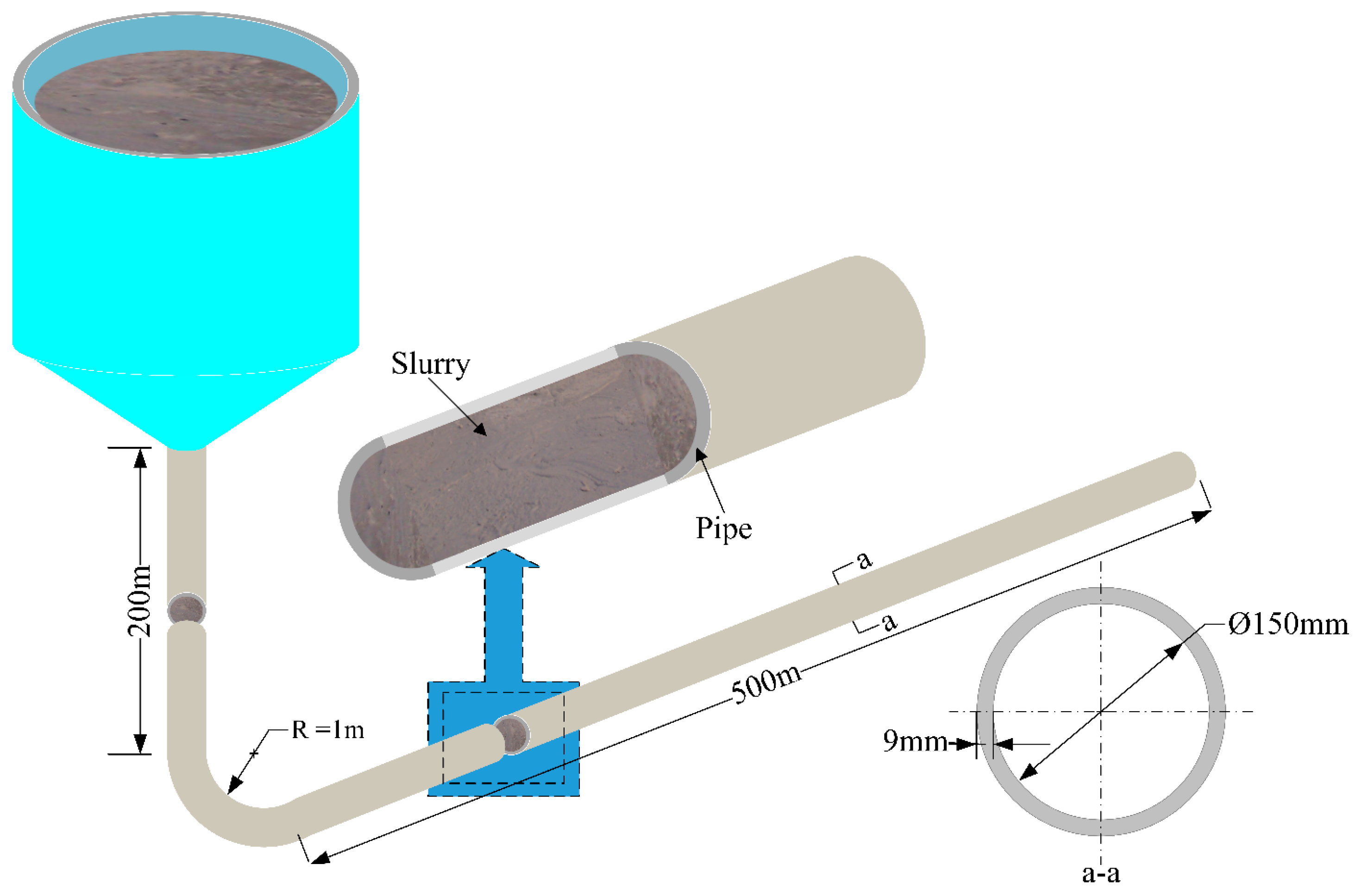
Figure 5.
Neutralization reaction of leaching residue.
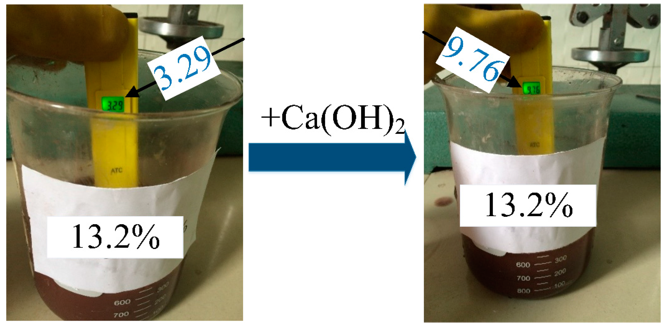
Figure 6.
The average compressive strength (curing age: 3 days, 7 days and 28 days) of the backfill body at each level.
Figure 6.
The average compressive strength (curing age: 3 days, 7 days and 28 days) of the backfill body at each level.
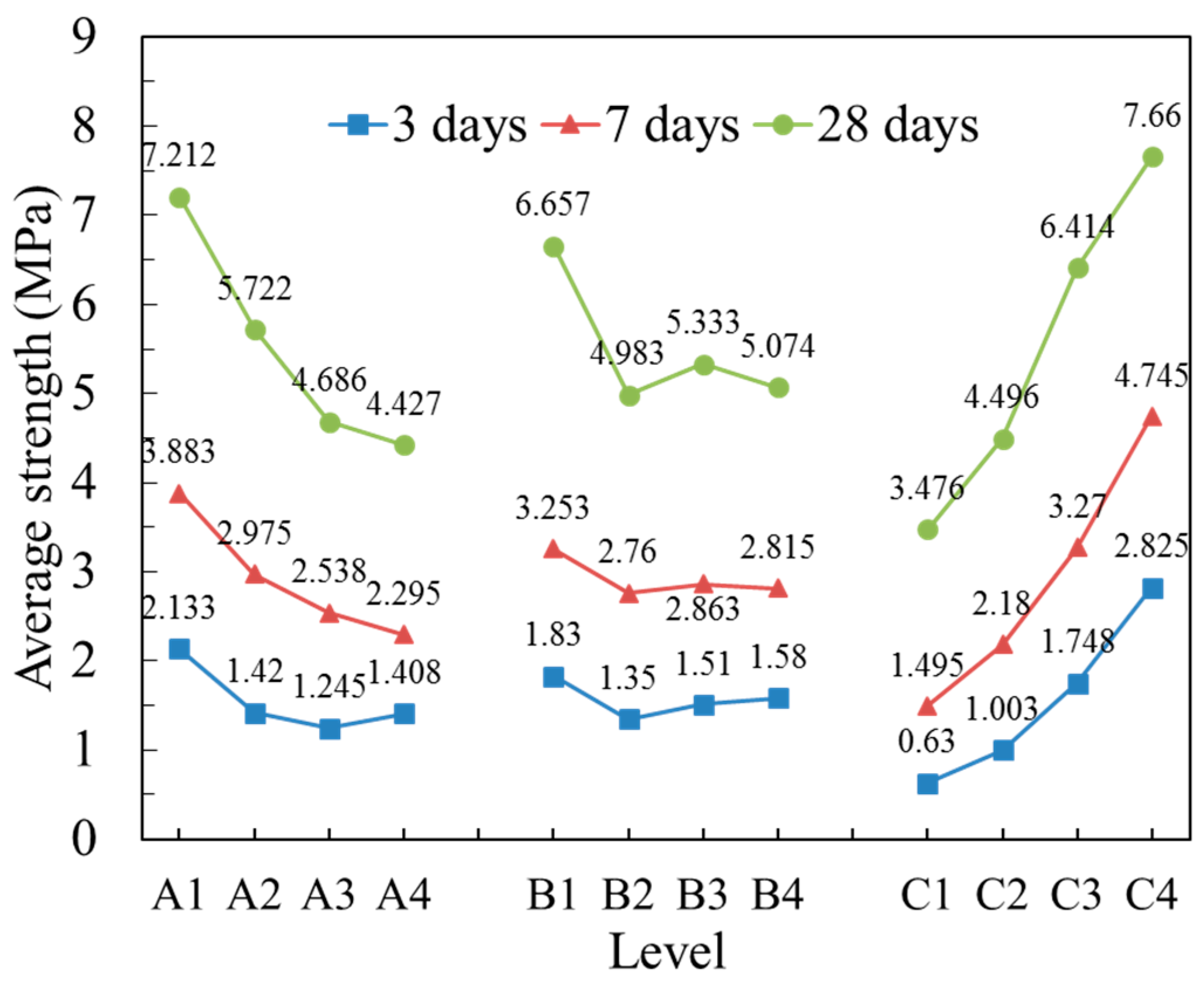
Figure 7.
The average diffusivity of the slurry at each level.

Figure 8.
Velocity contours at the elbow for different leaching residue:classified tailings mass ratios: (a) 1:6 and (b) 1:7.
Figure 8.
Velocity contours at the elbow for different leaching residue:classified tailings mass ratios: (a) 1:6 and (b) 1:7.
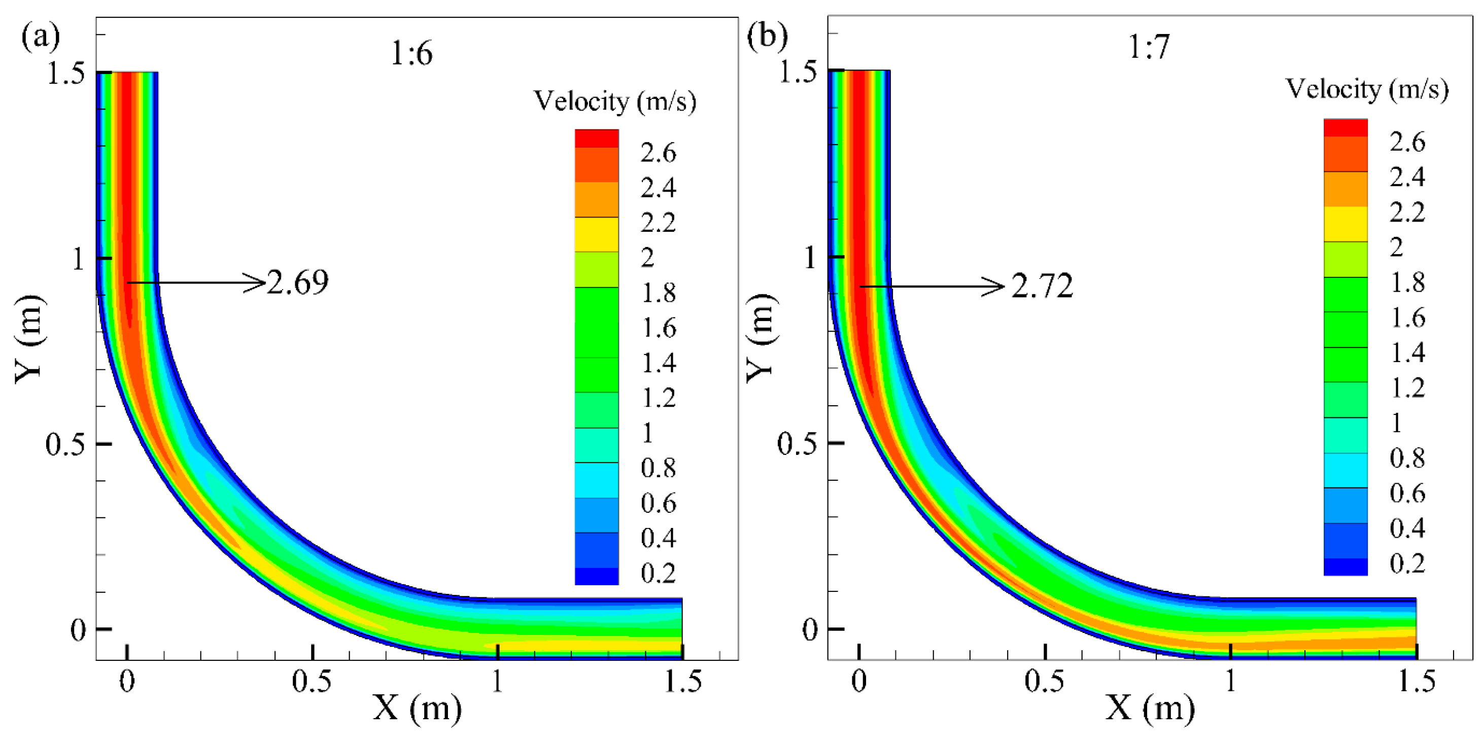
Figure 9.
Velocity contours at the outlet for different leaching residue:classified tailings mass ratios: (a) 1:6 and (b) 1:7.
Figure 9.
Velocity contours at the outlet for different leaching residue:classified tailings mass ratios: (a) 1:6 and (b) 1:7.

Table 1.
Physical properties of leaching residue and classified tailings.
| Tailings | Density (t/m3) | Average Unit Weight (kN/m3) | Porosity (wt %) | –19 µm Content (wt %) | () | Osmotic Coefficient (cm/h) | Slurry pH |
|---|---|---|---|---|---|---|---|
| leaching residue | 3.72 | 10.67 | 48.46 | 99.33 | 2.83 | 2.6 | 3.29–3.79 |
| classified tailings | 3.11 | 14.52 | 53.22 | 18.73 | 9.33 | 5.8 | 8.12–8.95 |
Table 2.
Chemical composition of leaching residue size and classified tailings (unit in wt %).
| Tailings | Zn | Pb | S | SiO2 | LOI | TiO2 | Al2O3 |
| leaching residue | 0.09 | 0.11 | 1.21 | 84.08 | 8.40 | 0.73 | 1.38 |
| classified tailings | 0.65 | 0.56 | 12.95 | 38.07 | 10.53 | 0.12 | 3.89 |
| Tailings | Fe2O3 | MnO | MgO | CaO | Na2O | K2O | P2O5 |
| leaching residue | 2.15 | 0.02 | 0.21 | 0.47 | <0.1 | 1.04 | 0.01 |
| classified tailings | 6.14 | 0.39 | 2.58 | 18.14 | 0.14 | 2.67 | 0.17 |
Table 3.
Extraction toxicity of the leaching residue (unit in mg/L).
| Metallic Element | Cu | Zn | Cd | Pb | Cr | Cr(VI) | Hg | Ni | Ag |
|---|---|---|---|---|---|---|---|---|---|
| Content | 3.59 | 36.8 | 0.05 | 3.61 | 0.00 | 0.00 | 0.0020 | 1.99 | 0.11 |
| Limited Value [27] | 100 | 100 | 1 | 5 | 15 | 5 | 0.1 | 5 | 5 |
Table 4.
The results of the compressive strength test and diffusivity test.
| Case | Factor | Compressive Strength (MPa) | Diffusivity (cm) | ||||
|---|---|---|---|---|---|---|---|
| Cement:Sand (Mass Ratio) (A) | Leaching Residue: Classified Tailings (Mass Ratio) (B) | Slurry Mass Concentration (C/wt %) | 3 Days | 7 Days | 28 Days | ||
| 1 | 1:3 | 1:4 | 67 | 1.06 | 2.35 | 6.11 | 246.50 |
| 2 | 1:4 | 1:4 | 69 | 1.26 | 2.87 | 6.30 | 188.50 |
| 3 | 1:5 | 1:4 | 71 | 1.75 | 3.56 | 6.92 | 105.00 |
| 4 | 1:6 | 1:4 | 73 | 3.25 | 4.23 | 7.30 | 90.50 |
| 5 | 1:3 | 1:5 | 69 | 1.39 | 2.96 | 5.29 | 256.50 |
| 6 | 1:4 | 1:5 | 67 | 0.61 | 1.53 | 3.30 | 297.50 |
| 7 | 1:5 | 1:5 | 73 | 2.07 | 4.02 | 5.77 | 104.00 |
| 8 | 1:6 | 1:5 | 71 | 1.33 | 2.53 | 5.57 | 185.00 |
| 9 | 1:3 | 1:6 | 71 | 2.37 | 4.28 | 7.85 | 163.50 |
| 10 | 1:4 | 1:6 | 73 | 2.27 | 4.79 | 7.97 | 109.50 |
| 11 | 1:5 | 1:6 | 67 | 0.73 | 1.03 | 2.59 | 326.50 |
| 12 | 1:6 | 1:6 | 69 | 0.67 | 1.35 | 2.92 | 259.00 |
| 13 | 1:3 | 1:7 | 73 | 3.71 | 5.94 | 9.60 | 139.50 |
| 14 | 1:4 | 1:7 | 71 | 1.54 | 2.71 | 5.32 | 199.00 |
| 15 | 1:5 | 1:7 | 69 | 0.69 | 1.54 | 3.47 | 287.00 |
| 16 | 1:6 | 1:7 | 67 | 0.38 | 1.07 | 1.91 | 359.50 |
Table 5.
Variance analysis of the compressive strength test and diffusivity test.
| Factor | Dependent Variable (Compression Strength) | Sum of Class III Squares | Freedom | Mean Square Deviation | F | Significance |
|---|---|---|---|---|---|---|
| A | 3 days strength | 1.878 | 3 | 0.626 | 5.039 | 0.044 |
| 7 days strength | 5.865 | 3 | 1.955 | 11.376 | 0.007 | |
| 28 days strength | 19.178 | 3 | 6.393 | 12.984 | 0.005 | |
| diffusivity | 1496.562 | 3 | 498.854 | 3.438 | 0.092 | |
| B | 3 days strength | 0.521 | 3 | 0.174 | 1.399 | 0.332 |
| 7 days strength | 0.602 | 3 | 0.201 | 1.167 | 0.397 | |
| 28 days strength | 7.259 | 3 | 2.420 | 4.914 | 0.047 | |
| diffusivity | 16,201.062 | 3 | 5400.453 | 37.222 | 0.000 | |
| C | 3 days strength | 11.243 | 3 | 3.748 | 30.165 | 0.001 |
| 7 days strength | 24.125 | 3 | 8.042 | 46.791 | 0.000 | |
| 28 days strength | 42.412 | 3 | 14.137 | 28.714 | 0.001 | |
| diffusivity | 91,701.812 | 3 | 30,567.271 | 210.688 | 0.000 |
Table 6.
The results of the compression strength test and diffusivity test.
| Case | Factor | Inlet Pressure (Pin/MPa) | Outlet Pressure (Pout/MPa) | Resistance (hf/MPa) | Gravitational Potential Energy (P/MPa) | Self-Flowing Transportation | ||
|---|---|---|---|---|---|---|---|---|
| Cement:Sand (Mass Ratio) (A) | Leaching Residue: Classified Tailings (Mass Ratio) (B) | Slurry Mass Concentration (C/wt %) | ||||||
| 1 | 1:3 | 1:6 | 71 | 0.0022 | 3.1776 | 3.1754 | 3.7965 | Yes |
| 2 | 1:3 | 1:7 | 71 | 0.0022 | 3.2497 | 3.2475 | 3.7984 | Yes |
Table 7.
The material content per day.
| Material | Cement (ton) | Leaching Residue (ton) | Classified Tailings (ton) | Water (ton) | The Output of Leaching Residue (ton) | Recovery Ratio (wt %) |
|---|---|---|---|---|---|---|
| Content | 36.4 | 15.6 | 93.6 | 59.5 | 80.0 | 19.5 |
© 2017 by the authors. Licensee MDPI, Basel, Switzerland. This article is an open access article distributed under the terms and conditions of the Creative Commons Attribution (CC BY) license (http://creativecommons.org/licenses/by/4.0/).
Share and Cite
MDPI and ACS Style
Chen, X.; Shi, X.; Zhou, J.; Chen, Q.; Yang, C. Feasibility of Recycling Ultrafine Leaching Residue by Backfill: Experimental and CFD Approaches. Minerals 2017, 7, 54. https://doi.org/10.3390/min7040054
AMA Style
Chen X, Shi X, Zhou J, Chen Q, Yang C. Feasibility of Recycling Ultrafine Leaching Residue by Backfill: Experimental and CFD Approaches. Minerals. 2017; 7(4):54. https://doi.org/10.3390/min7040054
Chicago/Turabian StyleChen, Xin, Xiuzhi Shi, Jian Zhou, Qiusong Chen, and Chao Yang. 2017. "Feasibility of Recycling Ultrafine Leaching Residue by Backfill: Experimental and CFD Approaches" Minerals 7, no. 4: 54. https://doi.org/10.3390/min7040054
Note that from the first issue of 2016, this journal uses article numbers instead of page numbers. See further details here.