Microwave-Supported Leaching of Electric Arc Furnace (EAF) Slag by Ammonium Salts


1
The State Key Laboratory of Refractories and Metallurgy, Wuhan University of Science and Technology, Wuhan 430081, China
2
The Key Laboratory of Extraordinary Bond Engineering and Advanced Materials Technology, Yangtze Normal University, Chongqing 408100, China
*
Author to whom correspondence should be addressed.
Minerals 2017, 7(7), 119; https://doi.org/10.3390/min7070119
Submission received: 1 June 2017
/
Revised: 1 July 2017
/
Accepted: 7 July 2017
/
Published: 13 July 2017
Abstract
:The effect of microwave-supported leaching of electric arc furnace (EAF) slag by ammonium salts was investigated to improve calcium leaching ratio for CO2 mineral sequestration process. The results show that the calcium leaching ratio from EAF slag at the constant temperature in the microwave field increases about 10% than that under the water bath at the same leaching time. The greater the microwave power, the higher the impact of calcium leaching rate, which proves that microwave treatment can improve the leaching ratio of calcium. The rapid calcium leaching step (up to 5 min) is possibly due to the easy reaction of calcium silicate, while the slower calcium leaching step (after 5 min) is owing to the difficult reaction of calcium ferroaluminates for the hydrolysis of iron and aluminum. The leaching behaviors of magnesium and calcium ions affected by different leaching parameters are similar and the concentration of aluminum, iron and phosphorus can be neglected. Calcium ion is probably not precipitated in the real leaching solution from steel slag by ammonium chloride solution as its concentration is less than 0.32 mol/L. However, the concentration of magnesium ion starts to drop sharply when the pH value is higher than 10 and it has precipitated completely at pH value of 11.6.
1. Introduction
As fossil fuels will still be the main power source in the near future and its combustion would emit significant amounts of greenhouse gases, an economically viable approach to sequestrate CO2 is becoming more and more necessary. Meanwhile, the worldwide production of crude steel has reached 1.63 × 10⁶ Mt in 2016 [1], large amounts of steel slag generated simultaneously, which are estimated to about 10~15% by weight of the total produced crude steel [2]. Furthermore, the iron and steel industry is recognized as one of the largest CO2 emission industries with total amounts of 1500~1600 Mt CO2 emission [3]. Currently, the waste steelmaking slag are mainly used as fluxing agent of iron and steel smelting [4,5], fertilizer of agricultural production [6,7], construction materials (such as slag cement, brick, concrete and construction aggregate) [8], soil conditioner [9], as well as adsorbent of environmental protection [10]. However, for these applications only a small part of the slag can be utilized, especially in China, where the utilization rate of steel slag is only 22%, which is far behind the developed countries [11]. The uses of CO2 in the waste off-gas and unused slag are limited for various causes and difficulties. Therefore, large amounts of slag are stockpiled, which are costly and seriously harmful to the environment, such as damaging soil and vegetation or polluting air and water.
In 1990, Seifritz proposed a safe and permanent method of CO2 sequestration based on chemically combining CO2 with abundant raw materials to form stable carbonate minerals [12]. It was improved by using waste slag to sequestrate CO2 due to significant levels of calcium, high alkalinity in the slag and in situ CO2 mineral carbonation in iron and steel plants. An approach involving calcium ion leaching from the waste slag with the ammonium salts, and subsequently reacting with CO2 to produce precipitation calcium carbonate (PCC), has been reported recently [13,14,15,16,17]. The usage of ammonium chloride solution as an extraction reagent in the indirect aqueous processes of CO2 sequestration is currently widely investigated for high efficiency and selective extraction of calcium and easy purification process. The process mainly consists of a two-step reaction as follows.
2CaO·SiO2(s) + 4NH4Cl(aq)→2CaCl2(aq) + 2H2O + SiO2(s)↓ + 4NH3(aq)
4NH3(aq) + 2CO2(aq) + 2CaCl2(aq) + 4H2O(l)→2CaCO3(s)↓ + 4NH4Cl(aq)
Ammonium chloride is consumed in the first step and regenerated in the second step, thus, the extraction agent can be recycled. Compared with ammonium salts leaching, the pH of the leached system needs to be improved after leaching for nitric acid and sulfuric acid to make the following carbonation reaction possible, while using acetic acid as a leaching solution would leach large amounts of other elements besides calcium, such as magnesium [18,19,20,21]. Therefore, the whole process cost would be reduced by using ammonium chloride as a leaching agent, due to fewer requirements for the pH adjusting and purification process. However, the calcium extraction efficiency with ammonium salts is much lower than that with acidic extraction. In order to improve the calcium leaching ratio from electric arc furnace (EAF) slag, this paper proposes the methods of assisting the calcium leaching in a microwave field and proves the possibility of improving calcium extraction efficiency from EAF slag, and the optimization of the process was also studied.
2. Experimental Procedure
The as-received carbon steel EAF slag was provided by a local steelmaking plant, and the main chemical composition of EAF slag was analyzed with inductively coupled plasma emission spectroscopy (IRIS Advantage ER/S) as 39% CaO, 28% Fe2O3, 12% SiO2, 8% MgO and 4% Al2O3, which indicates that it is suitable for mineral CO2 sequestration due to its high basicity (CaO/SiO2 > 2.7) and calcium content. A batch of 2 kg EAF slag was crushed in a vibratory disk mill and ground in a planet-type ball mill. The ground slag was subsequently dried in an oven at 110 °C for 24 h.
In order to compare the calcium extraction efficiency in the microwave leaching process, a first batch of leaching experiments at the constant temperature with water bath and in a microwave field were carried out in a three-necked flask, respectively. In the experiment, the particle size of EAF slag, which is smaller than 54 μm, was selected. The leaching process was assisted by magnetic stirring at the maximum rate, and the other leaching process parameters were 20 mL/g liquid–solid ratio, 200 mL solution volume and 2 mol/L ammonium chloride solution. Moreover, the effect of various leaching parameters (stirring speed, leaching solution volume, liquid-solid ratio, leaching solution concentration) on calcium leaching ratio from EAF slag was also studied on a second experimental batch at fixed temperature (60 °C) under microwave field, on EAF slag particles grinded less than 100 μm.
In the conventional leaching experiment, the reaction temperature was conducted with water bath and the leachant was stirred magnetically. The microwave chemical reactor MCR-3 can provide two kinds of microwave outputs, i.e., a stable microwave power and a stable temperature with variable microwave heating output. The experiment temperature in the microwave field was monitored with a trifluoroethylene thermocouple. Both conventional and microwave leaching experiments were equipped with a condenser pipe system.
In the microwave leaching process of constant temperature, the leaching solution was heated to the aimed temperature, then the EAF slag was added into the leaching solution and the microwave chemical reactor was switched on immediately, while the leaching reaction in the leaching process of constant microwave power begins from room temperature. At a certain time, a part of the reactant was sampled and filtered. The calcium concentrations of leachate were analyzed with the ethylenediaminetetraacetic acid (EDTA) titration method of GB/T 15452-2009 [22]. Moreover, the concentrations of magnesium, aluminum, iron and phosphorus at the final leaching solution were analyzed by inductively coupled plasma emission spectroscopy (IRIS Advantage ER/S, Thermo Jarrell Ash, Franklin, MA, USA). The filtered leached slag residue was washed with Reverse Osmosis water (RO water) three times and dried at 115 °C for 24 h. The mineralogical phases of the slag residue were determined by an X’Pert PRO MPD X-ray diffractometer with Cu Kα. A field emission scanning electron microscopy (Nova 400 NanoSEM, FEI, Hillsboro, OR, USA) coupled with energy dispersive spectrometer (INCAIE 350 PentaFET X-3 EDS, Oxford, UK) was used to analyse the as-received slag sample and the leached slag residue.
The leaching ratio of calcium ion was calculated by the following equation:
where is the leaching ratio of calcium; is the concentration of Ca2+ in the filtrate, μg/mL; VT is the total volume of the leaching solution, mL; is the mass of the EAF slag, g; is the content of CaO in the EAF slag, %; MCa, MCaO are the molecular mass of Ca and CaO, respectively.
3. Results and Discussion
3.1. Calcium Leaching by NH4Cl with Conventional and Microwave Leaching Processes
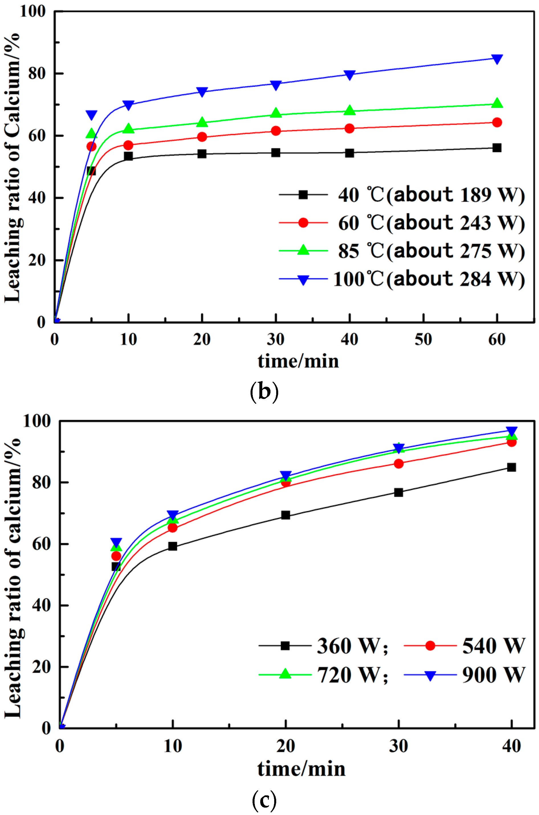
The calcium leaching ratio from the EAF slag by NH4Cl under different leaching environments are shown in Figure 1. It can be seen from Figure 1a that the calcium leaching ratio rose significantly at the initial period (5 min) and then tends to the maximum value, which attains ~87% with 120 min leaching at 100 °C. Figure 1b is the variation of calcium leaching ratio with leaching time at constant temperature in a microwave field. Comparing with Figure 1a,b, the tendencies of the calcium leaching ratios are similar, which attains the maximum leaching ratio within 5 min. However, the calcium leaching ratio at the constant temperature in the microwave field increases about 10% than that under the water bath at the same time. This is possibly due to the fact that the polar molecules in the leaching system vibrate rapidly in the microwave field, producing a large amount of energy, which heats the solution and increases the collision frequency between the slag materials and solution. Moreover, the fresh surfaces in the slag particles exposed on the crack caused by the microwave are beneficial for the extraction reaction [23,24,25].
It can be seen from Figure 1b,c that the greater the microwave power, the higher the impact of calcium leaching ratio, which proves that the thermal effect and non-thermal effect generated by the microwave field improve the leaching ratio. Meanwhile, the leaching solutions are boiling within several minutes at constant power in the microwave field. Therefore, the following experiments were further studied at the constant temperature in the microwave field.
XRD analysis of the as-received EAF slag and the leached slag residue after different leaching processes are shown in Figure 2. The crystalline phases of the as-received EAF slag, containing Ca(Fe,Al)2O5, CaFe(Si2O6), RO phase, CaCO3, CaMgSi2O6, CaSiO3, Ca2SiO4 and Ca3SiO5, are complex, while the crystalline phases of the leached slag residue at different leaching parameters are similar. Compared with the as-received EAF slag and the leached slag residue, it can be found that CaSiO3, Ca2SiO4 and Ca3SiO5 are disappeared and SiO2 is detected after the leaching process, which indicates that CaSiO3, Ca2SiO4 and Ca3SiO5 are dissolved in the ammonium chloride solution and SiO2 is produced.
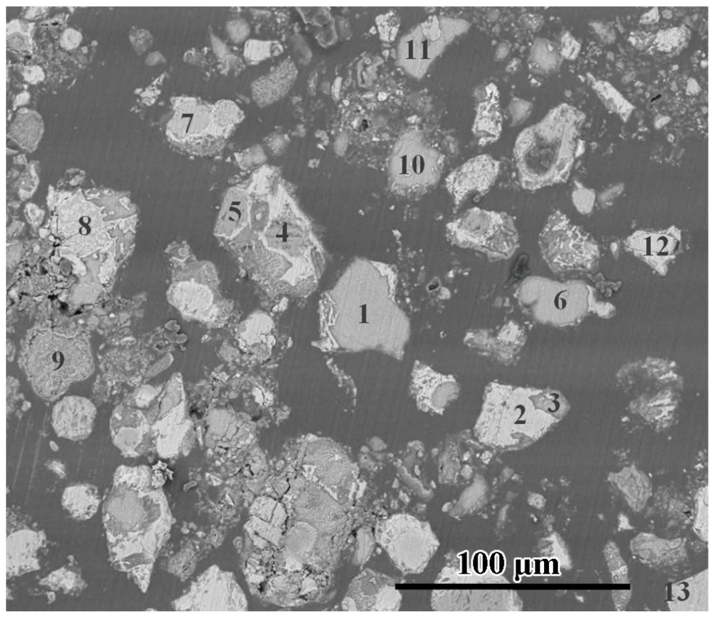
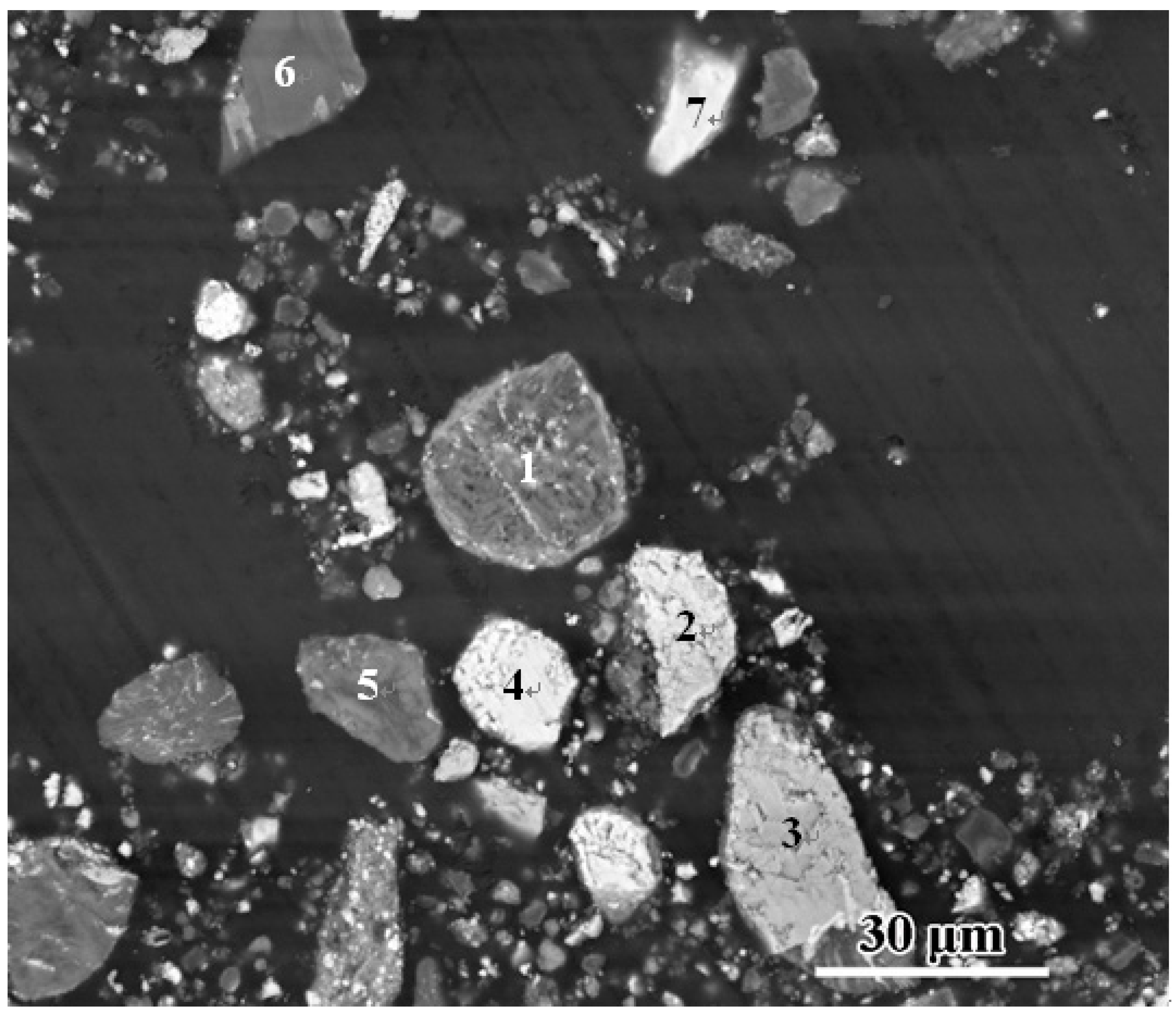
Figure 3 and Figure 4 are the SEM images of as-received EAF slag and the leached slag residue with microwave (85 °C) for 60 min, respectively. Table 1 shows the EDS results of the related compounds. Not only the phases detected in the XRD such as Ca2SiO4, Ca2(Fe,Al)2O5 and RO phase in Figure 3, but also the phases undetected in the XRD such as SiO2, f-CaO (free calcium oxide) and metal Fe are observed in the SEM images. This may be due to metallic iron and free lime being below the detection limit of conventional XRD. It can also be seen that the RO phase and calcium-ferrite solid solution often coexist with the calcium silicate [26,27]. Besides containing iron, the RO phase, with poor hydration activity, contains high magnesium. Calcium-ferrite solid solution usually contains aluminum existing as calcium ferroaluminates. In Figure 4, it is found that the particles with high contents of iron mainly contain RO phase and calcium ferroaluminates. The RO phase contains low calcium element at original phase, while the calcium ferroaluminates contain relatively high calcium element. Given that the calcium ferroaluminates in the slag residue leached by ammonium chloride solution still contain relatively high contents of calcium, it shows that the calcium in the form of calcium ferroaluminates is difficult to extract. Moreover, as the phosphorus is mainly dissolved in C2S and C3S in the steelmaking slag [28,29], the leached slag residue particles containing phosphorus, probably the calcium silicates before leaching, have high levels of silicon and less amounts of iron and calcium, which indicates that most of the calcium has been leached from C2S and C3S phases by ammonium chloride solution. The SEM results are consistent with the XRD analysis.
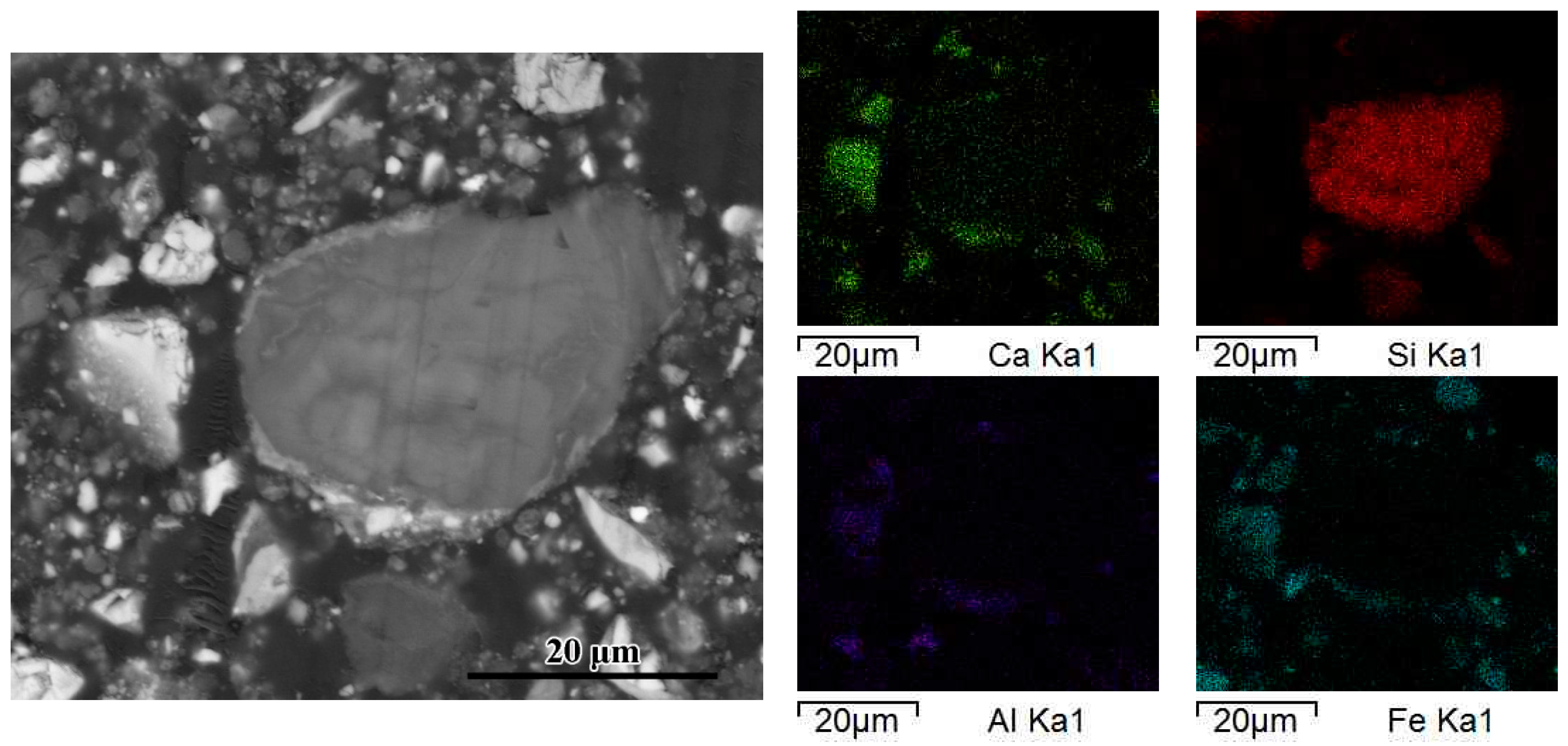
Figure 5 is the element mapping of typical leached slag residue with microwave power of 540 W for 10 min radiation. It shows that the particles with large amounts of calcium are rich in iron and aluminum, while those particles with less calcium are rich in silicon. Based on the thermodynamics analysis that calcium silicate and calcium ferroaluminates can react with ammonium chloride [30], as well as the fact that iron and aluminum will completely hydrolyze in the system of NH4Cl–NH3–H2O, it can predict that CaSiO3, Ca2SiO4 and Ca3SiO5 easily react in ammonium chloride solution and the hydrolysis of iron and aluminum on the surface of the particles hinders further calcium leaching from calcium ferroaluminates.
Since the principal phases of EAF slag are calcium silicate, RO phase and calcium ferroaluminates, and RO phase contains little calcium; the main calcium sources in the leaching reaction process are calcium silicate and calcium ferroaluminates. From Figure 1, the rapid calcium leaching step (up to 5 min) is possibly due to the easy reaction of calcium silicate, and the slower calcium leaching step (after 5 min) is owing to the difficult reaction of calcium ferroaluminates for the hydrolysis of iron and aluminum.
3.2. Effect of Different Leaching Parameters on Calcium Leaching Ratio from EAF Slag
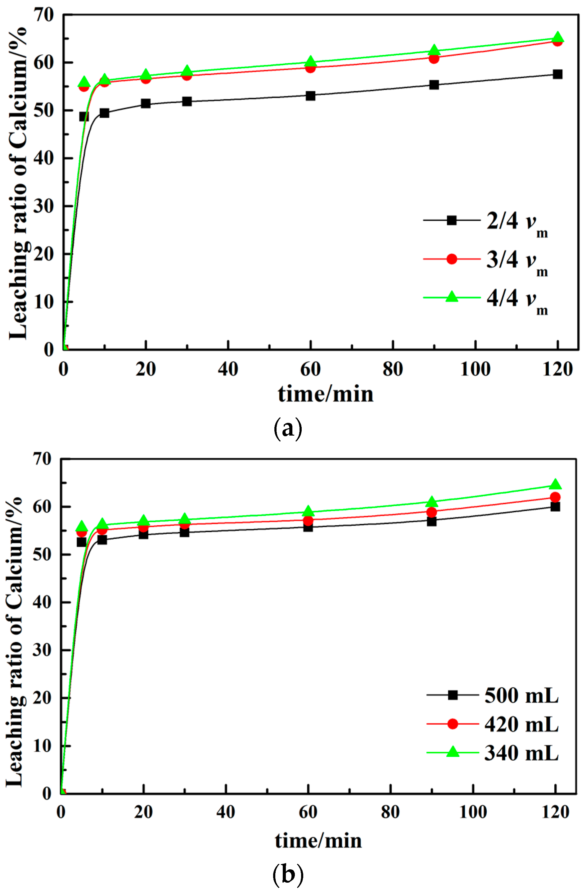
Although the leaching rate of calcium increases with the increasing of microwave power, the higher microwave power makes the solution temperature too high, even boiling and resulting in an overflow of ammonia, which goes against the absorption of carbon dioxide and the formation of calcium carbonate in the follow-up carbonate step. Therefore, the following calcium leaching experiments are studied at 60 °C under microwave fields. Figure 6 is the effect of different process parameters on the calcium leaching behavior. In Figure 6a, calcium leaching ratio increases significantly when the stirring rate is raised from 2/4 vm to 3/4 vm (vm is the maximum stirring rate of magnetic stirring); however, the leaching ratio does not increase much with the stirring rate increased from 3/4 vm to 4/4 vm. It indicates that the external diffusion is not the restrictive conditions of calcium leaching when the stirring is 3/4 vm. It is shown in Figure 6b that the calcium leaching ratio slightly increases with leaching solution volume decreasing, which may be due to the solution of the mixing intensity being relatively lower under a certain stirring rate when the reaction solution volume increased significantly. In Figure 6c,d, the calcium leaching ratio increases with the liquid–solid ratio increasing. Meanwhile, the concentration of calcium in the solution drops rapidly. Therefore, a suitable liquid–solid ratio is required considering the calcium leaching ratio and the concentration of calcium. With the concentration of ammonium chloride solution increasing, the concentration of calcium in the leachate rises (Figure 6e). It is possibly due to the fact that the lower pH value of the leaching system leaded by the higher concentration of ammonium chloride is favorable for the calcium leaching [2]. However, the excessive concentration of ammonium chloride solution is also not good to avoid impacting the absorption and precipitation of CO2 at the subsequent carbonate process.
As the extraction ratio of calcium in EAF slag is nearly 70% and reaction ratio of calcium in leaching solution with carbon dioxide almost reaches 100% [31], CO2 uptakes can be calculated as 306 g CO2/kg slag for the EAF slag containing 39% calcium oxide, compared to the thin-film condition and slurry-phase route (176~280 g CO2/kg slag) [3].
3.3. Leaching Behaviors of Impurity Ions from EAF Slag
Figure 7 is the variation of concentration of calcium, magnesium, aluminum, iron and phosphorus ions in the leached solution under different leaching parameters for 120 min. The concentration of aluminum, iron and phosphorus ions are less than 10−6 mol/L, which indicates that it can be neglected. In addition, the leaching behaviors of magnesium and calcium ions are similar. Although the concentration of magnesium is much less than that of calcium, it may be necessary to remove magnesium ion before the carbonate process [32,33].
3.4. Removal of Impurity Ions from the Leachate
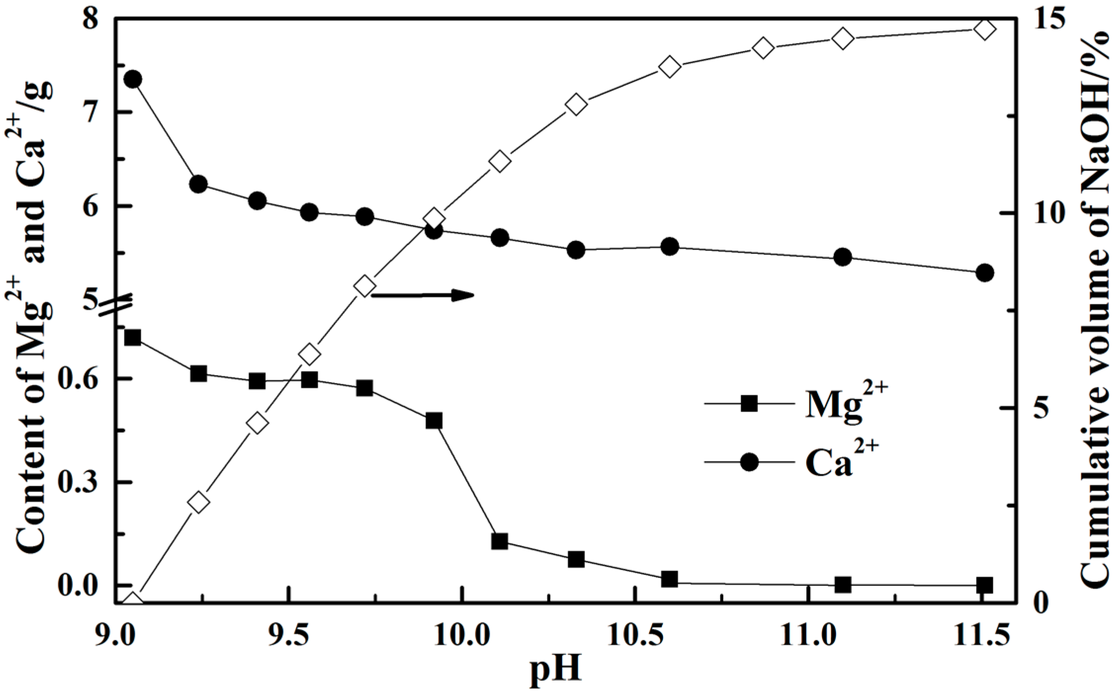
As the concentrations of aluminum, iron and phosphorus ions can be neglected, and magnesium ion is the major impurity in the leached solution, the removal of magnesium ion by adjusting pH value was studied. A 500 mL experimental solution was set up containing 0.5 mol/L CaCl2, 0.2 mol/L MgCl2, 1 mol/L NH3·H2O and 2 mol/L NH4Cl, and then the configured solution was shaken up and left standing for 24 h, after which the configured solution was filtered, and the filtrate was selected as the solution for the removal experiment of magnesium ion by adding 15 mol/L sodium hydroxide solution.
In Figure 8, it can be seen that the required volume of sodium hydroxide solution to raise the pH value of the solution reduces gradually, which is due to the buffering effect caused by the system of NH4Cl–NH4–H2O. In addition, the concentration of calcium in the solution, 0.32 mol/L when the pH value is 11.6, is still high, which indicates that the calcium ion is probably not precipitated in the real leaching solution from steel slag by NH4Cl solution as the calcium concentration of the real solution is less than 0.32 mol/L (Figure 7). This is important to obtain high carbonation efficiency, since only dissolved Ca can be used for CO2 sequestration. Indeed, Ca precipitation negatively affects CO2 uptake. For this reason, is important to allow only Mg precipitation, maintaining Ca ions in the solution. However, the concentration of magnesium ion starts to drop sharply when the pH value is higher than 10 and it has precipitated completely at pH value of 11.6. This is due to the solubility of calcium being much bigger than that of magnesium.
4. Conclusions
- (1)
- The calcium leaching ratio at the constant temperature in the microwave field increases about 10% than that under the water bath at the same time. The greater the microwave power, the higher the impact of calcium leaching ratio, which proves that microwave treatment can improve the leaching ratio. Meanwhile, the leaching solutions are boiling within several minutes at constant power in the microwave field.
- (2)
- The rapid calcium leaching step (up to 5 min) is possibly due to the easy reaction of calcium silicate and the slower calcium leaching step (after 5 min) is owing to the difficult reaction of calcium ferroaluminates for the hydrolysis of iron and aluminum.
- (3)
- The leaching behaviors of magnesium and calcium ions affected by different leaching parameters are similar and the concentration of aluminum, iron and phosphorus can be neglected.
- (4)
- Calcium ion is probably not precipitated in the real leaching solution from steel slag by NH4Cl solution as its concentration is less than 0.32 mol/L. However, the concentration of magnesium ion starts to drop sharply when the pH value is higher than 10 and it has precipitated completely at pH value of 11.6.
Acknowledgments
The authors gratefully acknowledge the National Natural Science Foundation of China (51374161).
Author Contributions
Zhibo Tong contributed to the experimental data and analysis presented in this manuscript; Guojun Ma contributed to the conception of the study and discussion on the experimental results; Xiang Zhang and Yongsheng Cai helped review this manuscript.
Conflicts of Interest
The authors declare no conflict of interest.
References
- Edwin, B. World Steel in Figures 2017; World Steel Association: Brussels, Belgium, 2017. [Google Scholar]
- Baciocchi, R.; Costa, G.; Polettini, A.; Pomi, R. Effects of thin-film accelerated carbonation on steel slag leaching. J. Hazard. Mater. 2015, 286, 369–378. [Google Scholar] [CrossRef] [PubMed]
- Baciocchi, R.; Costa, G.; Di Gianfilippo, M.; Polettini, A.; Pomi, R.; Stramazzo, A. Thin-film versus slurry-phase carbonation of steel slag: CO2 uptake and effects on mineralogy. J. Hazard. Mater. 2015, 283, 302–313. [Google Scholar] [CrossRef] [PubMed]
- Topkaya, Y.; Sevinç, N.; Günaydın, A. Slag treatment at kardemir integrated iron and steel works. Int. J. Miner. Process. 2004, 74, 31–39. [Google Scholar] [CrossRef]
- Tong, Z.B.; Ma, G.J.; Cai, X.; Xue, Z.L.; Wang, W.; Zhang, X. Characterization and valorization of kanbara reactor desulfurization Waste Slag of Hot Metal Pretreatment. Waste Biomass Valoriz. 2016, 7, 1–8. [Google Scholar] [CrossRef]
- Wang, W.; Sardans, J.; Lai, D.; Wang, C.; Zeng, C.; Tong, C.; Liang, Y.; Peñuelas, J. Effects of steel slag application on greenhouse gas emissions and crop yield over multiple growing seasons in a subtropical paddy field in China. Field Crops Res. 2015, 171, 146–156. [Google Scholar] [CrossRef]
- Wang, X.; Cai, Q.-S. Steel slag as an iron fertilizer for corn growth and soil improvement in a pot experiment. Pedosphere 2006, 16, 519–524. [Google Scholar] [CrossRef]
- Huang, X.; Wang, Z.; Liu, Y.; Hu, W.; Ni, W. On the use of blast furnace slag and steel slag in the preparation of green artificial reef concrete. Constr. Build. Mater. 2016, 112, 241–246. [Google Scholar] [CrossRef]
- Das, B.; Prakash, S.; Reddy, P.; Misra, V. An overview of utilization of slag and sludge from steel industries. Resour. Conserv. Recycl. 2007, 50, 40–57. [Google Scholar] [CrossRef]
- Kang, H.; An, K.; Kim, D. Utilization of steel slag as an adsorbent of ionic lead in wastewater. J. Environ. SCI Health 2004, 39, 3015–3028. [Google Scholar] [CrossRef]
- Yi, H.; Chen, H. An overview of utilization of steel slag. Int. Conf. Waste Manag. Technol. Chin. Soc. Environ. Sci. 2012, 16, 791–801. [Google Scholar] [CrossRef]
- Seifritz, W. CO2 disposal by means of silicates. Nature 1990, 345, 486. [Google Scholar] [CrossRef]
- Teir, S.; Eloneva, S.; Fogelholm, C.; Zevenhoven, R. Dissolution of steelmaking slags in acetic acid for precipitated calcium carbonate production. Energy 2007, 32, 528–539. [Google Scholar] [CrossRef]
- Hall, C.; Large, D.; Adderley, B.; West, H. Calcium leaching from waste steelmaking slag: Significance of leachate chemistry and effects on slag grain mineralogy. Miner. Eng. 2014, 65, 156–162. [Google Scholar] [CrossRef]
- Sun, Y.; Yao, M.; Zhang, J.; Yang, G. Indirect CO2 mineral sequestration by steelmaking slag with NH4Cl as leaching solution. Chem. Eng. J. 2011, 173, 437–445. [Google Scholar] [CrossRef]
- Kodama, S.; Nishimoto, T.; Yamamoto, N.; Yogo, K.; Yamada, K. Development of a new pH-swing CO2 mineralization process with a recyclable reaction solution. Energy 2008, 33, 776–784. [Google Scholar] [CrossRef]
- Fagerlund, J.; Nduagu, E.; Romão, I.; Zevenhoven, R. CO2 fixation using magnesium silicate minerals part 1: Process description and performance. Energy 2012, 41, 184–191. [Google Scholar] [CrossRef]
- Doucet, F. Effective CO2-specific sequestration capacity of steel slags and variability in their leaching behaviour in view of industrial mineral carbonation. Miner. Eng. 2010, 23, 262–269. [Google Scholar] [CrossRef]
- Eloneva, S.; Teir, S.; Salminen, J.; Fogelholm, C.; Zevenhoven, R. Fixation of CO2 by carbonating calcium derived from blast furnace slag. Energy 2008, 33, 1461–1467. [Google Scholar] [CrossRef]
- Chiang, Y.; Santos, R.; Elsen, J.; Meesschaert, B.; Martens, J.A.; Gerven, T. Towards zero-waste mineral carbon sequestration via two-way valorization of ironmaking slag. Chem. Eng. J. 2014, 249, 260–269. [Google Scholar] [CrossRef]
- Kakizawa, M.; Yamasaki, A.; Yanagisawa, Y. A new CO2 disposal process via artificial weathering of calcium silicate accelerated by acetic acid. Energy 2001, 26, 341–354. [Google Scholar] [CrossRef]
- CN-GB. GB/T 15452–2009 Industrial Circulating Cooling Water-Determination of Calcium and Magnesium-EDTA Titration Method; Standardization Administration of China: Beijing, China, 2009. [Google Scholar]
- Al-Harahsheh, M.; Kingman, S. Microwave-assisted leaching-A review. Hydrometallurgy 2004, 73, 189–203. [Google Scholar] [CrossRef]
- Bayca, S. Microwave radiation leaching of colemanite in sulfuric acid solutions. Sep. Purif. Technol. 2013, 105, 24–32. [Google Scholar] [CrossRef]
- Madakkaruppan, V.; Pius, A.; Sreenivas, T.; Giri, N.; Sarbajna, C. Influence of microwaves on the leaching kinetics of uraninite from a low grade ore in dilute sulfuric acid. J. Hazard. Mater. 2016, 313, 9–17. [Google Scholar] [CrossRef] [PubMed]
- Wang, Y.; Ye, G. A study of the mineral phases of oxygen converter slag and their cementious properties. J. Chin. Ceram. Soc. 1981, 9, 302–308. [Google Scholar]
- Dong, O.; Yuping, X.; Junyuan, H. Composition, mineral morphology and cementitious properties of converter slag. J. Chin. Ceram. Soc. 1991, 19, 488–494. [Google Scholar]
- Wu, X.; Wang, P.; Li, L.; Wu, Z.; Chen, R. Distribution and enrichment of phosphorus in solidified BOF steelmaking slag. Ironmak. Steelmak. 2013, 38, 185–188. [Google Scholar] [CrossRef]
- Li, G.H.; Wu, B.; Zhang, Y.B.; Zhang, K.C.; Chen, Y.L.; Jiang, T. Mineralogical characteristics and comprehensive utilization of converter steel slag. J. Cent. South Univ. 2010, 41, 2065–2071. [Google Scholar]
- Zhang, X.; Ma, G.J.; Tong, Z.B.; Xue, Z.L. Microwave-assisted selective leaching behavior of calcium from Basic Oxygen Furnace (BOF) slag with ammonium chloride solution. J. Min. Metall. B. 2017, 2, 139–146. [Google Scholar] [CrossRef]
- Tong, Z.B. Basic research of microwave strengthening calcium leaching from EAF steelmaking slag by ammonium salts and its fixation of carbon dioxide. Wuhan Univ. Sci. Technol. 2017, in press. [Google Scholar]
- Lackner, K.S.; Wendt, C.H.; Butt, D.P.; Joyce, E.L., Jr.; Sharp, D.H. Carbon dioxide disposal in carbonate minerals. Energy 1995, 20, 1153–1170. [Google Scholar] [CrossRef]
- Alamdari, A.; Alamdari, A.; Mowla, D. Kinetics of calcium carbonate precipitation through CO2 absorption from flue gas into distiller waste of soda ash plant. J. Ind. Eng. Chem. 2014, 20, 3480–3486. [Google Scholar] [CrossRef]
Figure 1.
Calcium leaching ratio from the electric arc furnace (EAF) slag by NH4Cl under the different environments: (a) at constant temperature under water bath; (b) at constant temperature in the microwave field; (c) at constant power in the microwave field.
Figure 1.
Calcium leaching ratio from the electric arc furnace (EAF) slag by NH4Cl under the different environments: (a) at constant temperature under water bath; (b) at constant temperature in the microwave field; (c) at constant power in the microwave field.
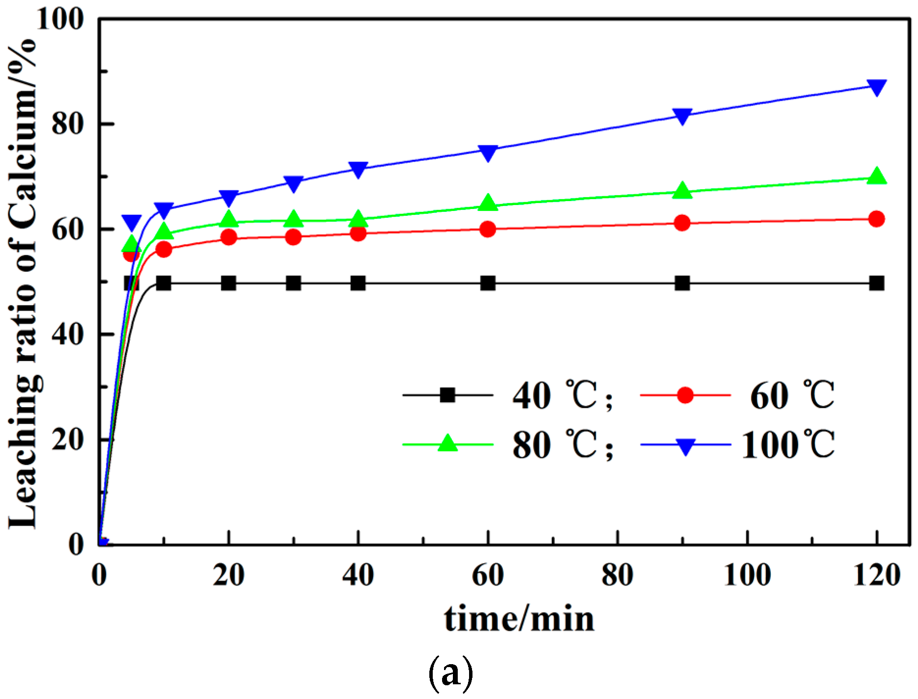

Figure 2.
Representative XRD pattern of slag under different process (Cu Kα) (▲ CaFA; ○ Ca3Fe2(SiO4)3; * CaFe(SiO3)2; ♦ CaMgSi2O6; ● RO; ■ CaCO3; △CS; □C2S; ▼ C3S; ► SiO2; ◄ MgO). (a) as-received EAF slag; (b) leached slag residue without microwave (85 °C); (c) leached slag residue with microwave (85 °C); (d) leached slag residue with microwave (540 W).
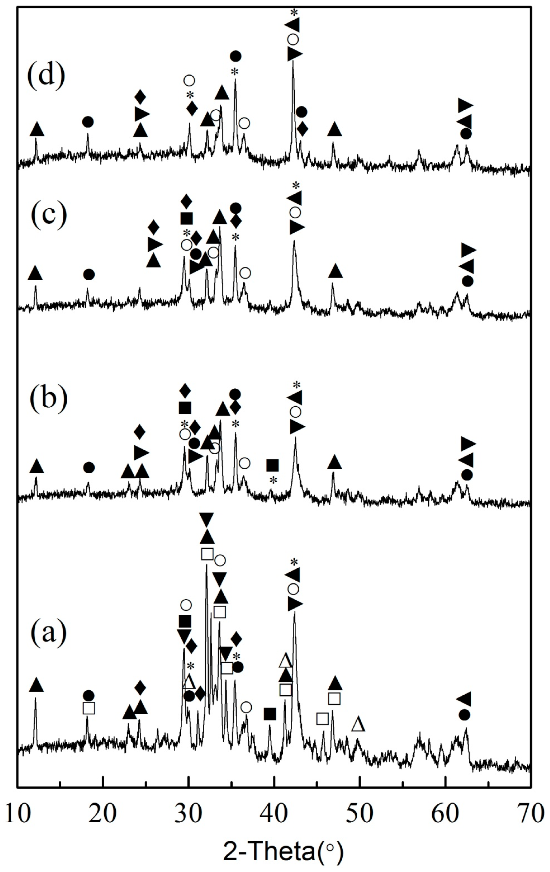
Figure 3.
The SEM images of as-received EAF slag.

Figure 4.
The SEM images of leached slag residue with microwave (85 °C) for 60 min.

Figure 5.
Element mapping of typical leached slag with 540 W microwave (10 min).

Figure 6.
Effect of different technological parameters on calcium leaching: (a) the stirring speeds; (b) the volume of leaching solution; (c,d) the liquid-solid ratio; (e) the leaching solution concentration.
Figure 6.
Effect of different technological parameters on calcium leaching: (a) the stirring speeds; (b) the volume of leaching solution; (c,d) the liquid-solid ratio; (e) the leaching solution concentration.

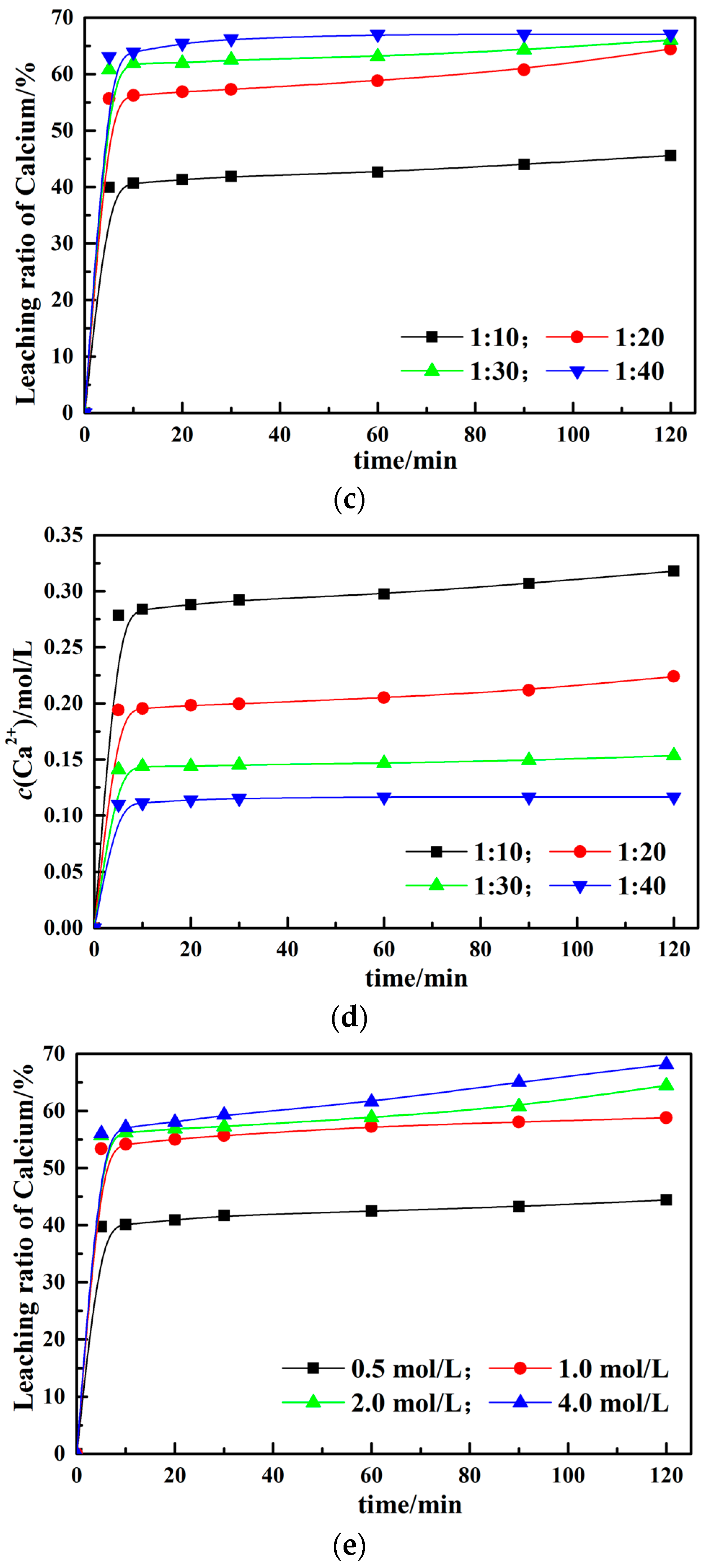
Figure 7.
Effect of different experimental parameters on Men+ leaching: (a) the stirring speeds; (b) the volume of leaching solution; (c) the liquid–solid ratio; (d) the leaching solution concentration.
Figure 7.
Effect of different experimental parameters on Men+ leaching: (a) the stirring speeds; (b) the volume of leaching solution; (c) the liquid–solid ratio; (d) the leaching solution concentration.
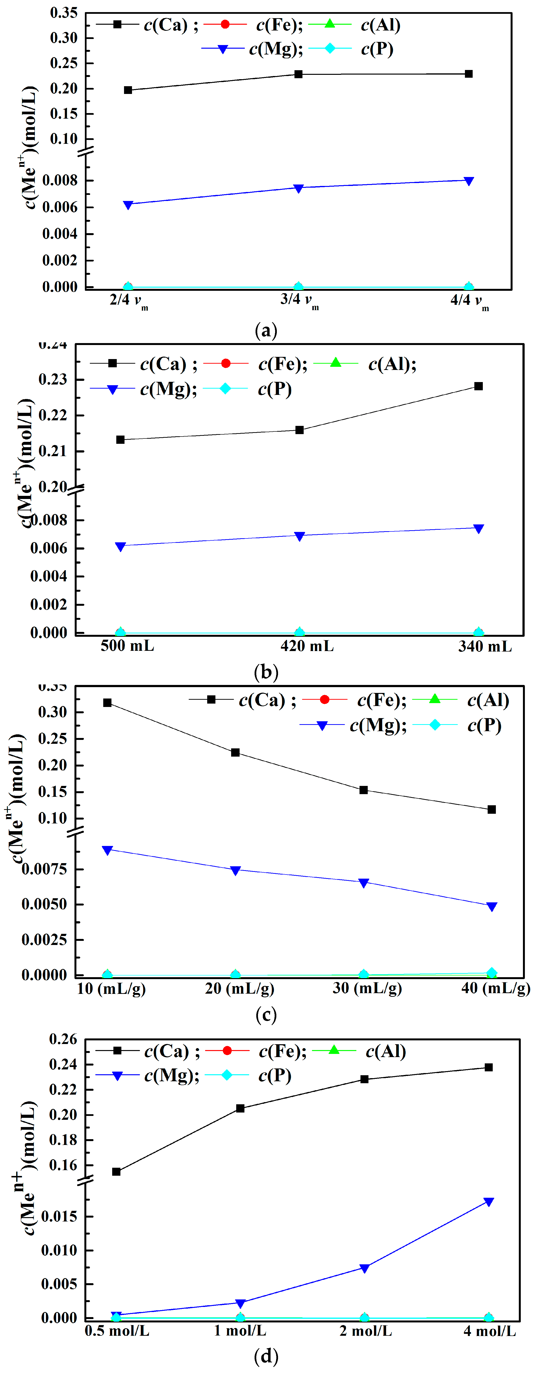
Figure 8.
The added volume of NaOH and the content of Mg2+/Ca2+ versus pH.

Table 1.
The related results of energy dispersive spectrometer (EDS) (Atomic percent)/%.
| Spectrum | Mg | Al | Si | P | Ca | Mn | Fe | Possible Phase | |
|---|---|---|---|---|---|---|---|---|---|
| Figure 3 | 1 | 33.31 | 65.3 | 1.36 | Ca2SiO4(C/S = 1.96) | ||||
| 2 | 54 | 1.58 | 3.23 | 41.22 | RO phase | ||||
| 3 | 32.54 | 66.2 | 1.29 | Ca2SiO4(C/S = 2.03) | |||||
| 4 | 75.4 | 1.79 | 22.8 | RO phase | |||||
| 5 | 76.8 | 0.84 | 2.32 | 20.04 | RO phase | ||||
| 6 | 31.98 | 68 | Ca2SiO4(C/S = 2.13) | ||||||
| 7 | 62.6 | 2.03 | 35.4 | RO phase | |||||
| 8 | 59 | 3.64 | 37.34 | RO phase | |||||
| 9 | 6.55 | 5.59 | 66.9 | 4.34 | 16.66 | - | |||
| 10 | 32.24 | 66.3 | 1.42 | Ca2SiO4(C/S = 2.07) | |||||
| 11 | 31.88 | 67.2 | 0.9 | Ca2SiO4(C/S = 2.11) | |||||
| 12 | 13.37 | 50.5 | 36.18 | CaFA(C/(A + F) = 1.02) | |||||
| 13 | 59.1 | 5 | 35.94 | RO phase | |||||
| Figure 4 | 1 | 1.85 | 1.39 | 63.84 | 4.64 | 23.48 | 1.01 | 3.79 | Calcium silicate after leached |
| 2 | 51.47 | 2.32 | 3.40 | 42.81 | RO phase | ||||
| 3 | 68.96 | 0.92 | 3.15 | 26.98 | RO phase | ||||
| 4 | 33.39 | 0.14 | 1.25 | 5.28 | 59.94 | RO phase | |||
| 5 | 1.12 | 1.90 | 55.37 | 13.43 | 24.99 | 3.19 | Calcium silicate after leached | ||
| 6 | 2.91 | 4.23 | 62.41 | 8.42 | 18.33 | 1.17 | 2.53 | Calcium silicate after leached | |
| 7 | 9.60 | 1.44 | 47.54 | 41.42 | CaFA(C/(A + F) = 0.93) |
© 2017 by the authors. Licensee MDPI, Basel, Switzerland. This article is an open access article distributed under the terms and conditions of the Creative Commons Attribution (CC BY) license (http://creativecommons.org/licenses/by/4.0/).
Share and Cite
MDPI and ACS Style
Tong, Z.; Ma, G.; Zhang, X.; Cai, Y. Microwave-Supported Leaching of Electric Arc Furnace (EAF) Slag by Ammonium Salts. Minerals 2017, 7, 119. https://doi.org/10.3390/min7070119
AMA Style
Tong Z, Ma G, Zhang X, Cai Y. Microwave-Supported Leaching of Electric Arc Furnace (EAF) Slag by Ammonium Salts. Minerals. 2017; 7(7):119. https://doi.org/10.3390/min7070119
Chicago/Turabian StyleTong, Zhibo, Guojun Ma, Xiang Zhang, and Yongsheng Cai. 2017. "Microwave-Supported Leaching of Electric Arc Furnace (EAF) Slag by Ammonium Salts" Minerals 7, no. 7: 119. https://doi.org/10.3390/min7070119
Note that from the first issue of 2016, this journal uses article numbers instead of page numbers. See further details here.