Determination of Seismic Safety Zones during the Surface Mining Operation Development in the Case of the “Buvač” Open Pit


Faculty of Mining Prijedor, University of Banja Luka, Prijedor 79101, Republic of Srpska, Bosnia and Herzegovina
*
Author to whom correspondence should be addressed.
Minerals 2018, 8(2), 71; https://doi.org/10.3390/min8020071
Submission received: 14 December 2017
/
Revised: 29 January 2018
/
Accepted: 12 February 2018
/
Published: 16 February 2018
(This article belongs to the Special Issue Selected Papers from the 6th International Symposium on Mining and Environmental Protection)
Abstract
:Determination of the blasting safety area is a very important step in the process of drilling and blasting works, and the preparation of solid rock materials for loading. Through monitoring and analysis of the negative seismic effects to the objects and infrastructures around and at the mine area, we were able to adapt the drilling and blasting parameters and organization of drilling and blasting operation according to the mining progress so that the affected infrastructures could be protected. This paper analyses the safety distances and model safety zones of drilling and blasting for the period 2013–2018 at the open pit at “Buvač”, Omarska. This mathematical calculation procedure can be used during the whole life of the mine. By monitoring of the blasting seismic influence in first years of the mine’s work, as well as by using recorded vibration velocities, mathematical dependence of the important parameters can be defined. Additionally, the level and laws of distribution and intensity of the seismic activity can be defined. On one hand, those are known quantities of the explosive and the distances between blasting location and endangered objects. On the other hand, those are coefficients of the manner of blasting and the environment where blasting is done, K, as well as the coefficient of the weakening of seismic waves as they spread, n. With the usage of the allowed vibration velocities, based on certain safety criteria and mathematical formulas of laws of spreading and intensity of seismic influence for a concrete case, it is possible to calculate explosive quantities and distances, with numerically-defined values of parameter K and n. Minimum distances are calculated based on defined or projected explosive quantities. Additionally, we calculate the maximum allowed explosive quantities based on known distances which can be used based on projected drilling-blasting parameters. For the purpose of the planning of drilling and blasting it is possible to define the allowed explosive quantities or minimum allowed distances in any area of the surface pit from the aspect of seismic safety. In the indicated case, and based on the analysis results, it is shown that in some areas of mining works in the case of the “Buvač”, Omarska open pit, projected explosive quantities cannot be used. In some cases, it is even necessary to divide the explosive charge in blasting holes with additional delayers.
1. Introduction
Explosive energy is used to break rock. However, the use of this energy is not 100% efficient. Some of the energy escapes into the atmosphere to generate air blast or air vibrations. Some of the energy also leaves the blast site through the surface soil and bedrock in the form of ground vibrations [1,2,3].
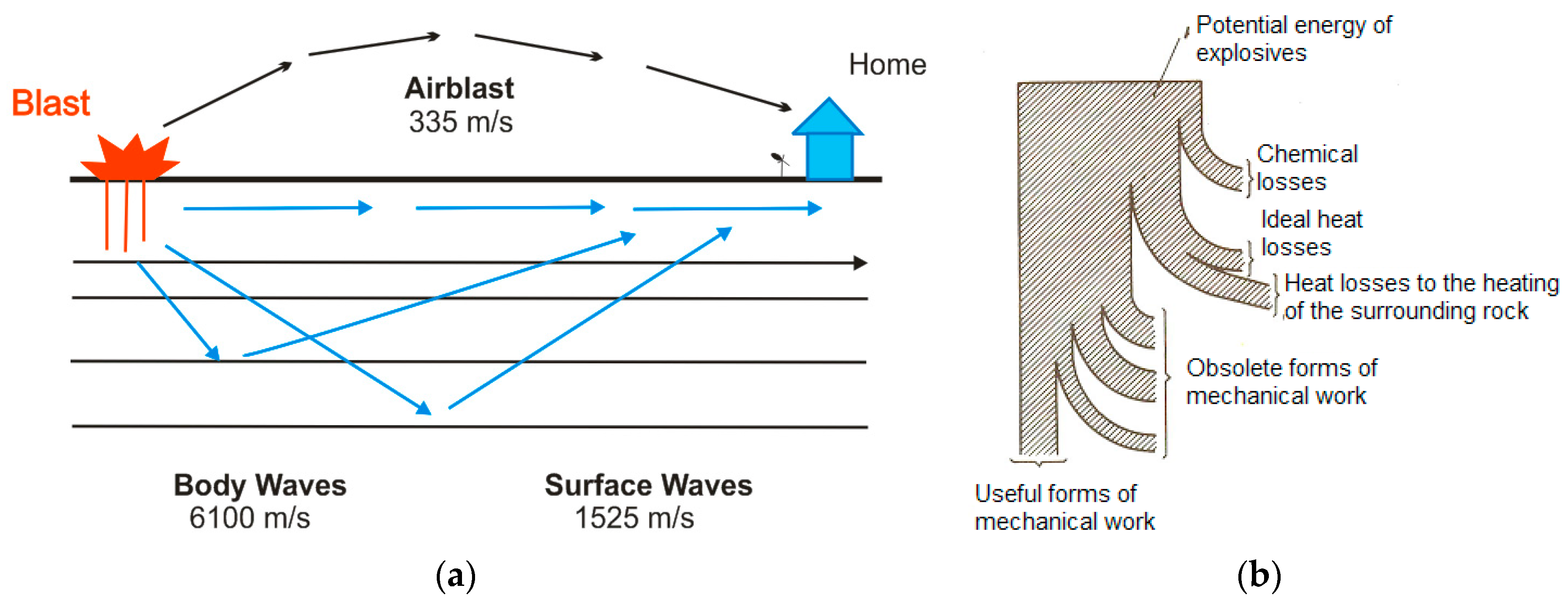
Waves of air vibrations and soil vibrations disturb the material and massif causing their movement when they encounter buildings or structures, causing their shaking. Vibrations of soil enter the house through the basement or foundations, and air waves affect the house over the walls and roof (Figure 1a). Air blast may be audible (noise) or inaudible (the shaking of the surface of the Earth). When outside a house the blast may be heard because of the noise, however, noise has little impact on the structure. The shaking of the surface of the Earth wave causes the structure to shake and rattles objects hanging on walls or sitting on shelves inside the building. This “interior noise” will alarm and startle people living in the house [1,4,5,6].
It is necessary to analyse these vibration impacts on facilities/buildings and constructions on the mine (offices, workshops, etc.), residential buildings around the mines—schools, churches, high voltage power lines, underground pipelines, etc.—but also on objects of cultural and historical heritage, sensitive also at lower vibration magnitude [1,4,5,6].
Flying rocks, as a second kind of the environment detrimental impact during drilling and blasting, are debris materials in the explosion and they travel through the air or on the ground. Flying rocks are the single most dangerous adverse effect that can cause property damage and personal injury or death, but it is not the subject of this analysis.
Seismic effects of explosion: In the case when explosives are detonated a sudden release of energy is just partly consumed in the crushing of rock mass. The biggest part of energy is being consumed on crushed mass spreading, heating of the environment, and other useless forms of work, such as the creation of the vibration/seismic waves (Figure 1b) [1,2,3,6,7].
The study of rock stresses and their changes is of great importance for safety in mines. Determination of measurable seismic velocities instead of the more difficult to measure stresses in the rocks has been investigated in a number of works where, e.g., imaging of blast damage may provide useful information for blast monitoring to characterize the damage zone, to verify blast damage models, and to optimize blasting strategies. Some problems on safety in blasting practice are discussed in these papers, including the attenuation law of ground motion in blasting operation, ground motion in blasting, and blasting isolation design and duration of ground motion in blasting [8,9,10].
The energy of seismic waves is manifested in the form of ground vibration. Shaking of the ground surface has stronger or weaker intensity, which depends on the distance (r) and the quantity of explosive (Q) that is activated in a simultaneous time interval. Additionally, the intensity of shaking of the ground surface depends on the blasting method, as well as the physical and mechanical properties of the soil and the characteristics of seismic earthquake damping [2,3,4,10,11].
The aim of this paper is the planning of blasting works at the iron ore “Buvač” open pit, Omarska, from the aspect of safety or determination of the safety zones—safety distances in blasting at this “Buvač” open pit, Omarska. Since the mining works are generally developed in the north–south direction, there are areas where housing and industrial facilities need to be protected from the permitted seismic shaking, induced by drilling and blasting activities, which are examined in the period 2013–2018 [7].
By determining the calculation procedure for seismically-safe distances, using certain safety criteria, it is possible to plan the maximum permitted explosive quantity in time and space, or minimum seismic safety distances to the endangered objects using designed or planned explosive quantities. In this paper we did not conduct a change in the hole pattern, the geometry of minefields, or explosive types, but we partially analysed the blasting design in terms of a delay number (not only in the mine field itself but, also, if needed in the blast holes) and the quantity of explosives that can be used.
2. Materials and Methods
The safety zones for blasting operation are defined as the space in which shaking of the ground surface (impacts of air waves and the ground vibration), flying rocks, or gases produced by blasting can cause personal injury or damage to the buildings. When defining these zones we recognize the following parameters and factors: the geological ground composition, the blasting method, the conditions of the drilling with the parameters, such as hole diameter, depth, and angle, the experience of the blasting at the mine, the delay system and an explosive factor with the quantity of explosives per ignition interval, the type and quantity of explosive material, and the type and amount of cork, etc. [2,4,11,12].
In this sense, it is necessary to work continuously on the development of the Program of experimental determination of the seismic effects degree in blasting on the surrounding residential buildings and the mine facilities where the main goal is to establish measures to reduce them with optimal technical blasting effects. Such programs would include the following activities:
- -
- monitoring of the existing state of constructions, infrastructural, and other objects’ conditions in the mine environment and at the mine;
- -
- the monitoring and recording of seismic shaking of the ground surface in blasting;
- -
- the maximum permitted explosive quantity by simultaneous ignition in specific conditions; and
- -
- optional determination of the optimal delay interval and possible alteration of other drilling and blasting parameters.
Based on the defined drilling and blasting parameters according to the project documentation—available drilling rigs, projected geometry of minefields, selected explosive types and other blasting-explosive materials—we define zones where there are industrial and residential buildings that can be endangered. When determining the mathematical dependence for specific working conditions, meaning the law of the spreading of seismic activity intensity, the allowed vibration velocities for defining and calculation of allowed explosive quantities or minimum distances with projected explosive quantities are used. In the concrete case, three areas of the surface pit are defined. Those are locations of blast fields with potential critical distances from endangered objects:
- Southwest zone on the pit (MP1-bench B120 west);
- Central south zone on the pit (MP2-bench B110 south); and
- Southeast zone on the pit (MP3-benchB120 east).
The “Buvač” open pit has been operating since 2009, and to model the drilling and blasting works in time and space monitoring of these works was carried out from the aspect of defining the safety seismic distances or allowed explosive quantities in relation to the endangered objects on the mine and its immediate surroundings. Measurements were performed and it was concluded that the velocity, determined by the seismograph, were in the range of 1.2 to 2.1 mm/s.
The results of the measurements in the later period were used as one form of verification of the executed calculations based on the determined distances or designed explosive quantities as the explosive quantities were reduced.
Based on this, this paper provides the procedure and order of certain activities that enable the creation of a method for the modelling of seismically-safe drilling and blasting zones:
- -
- Blasting monitoring in order to determine a mathematical model, meaning the functional dependence of parameters Q, explosive quantity; R, distance; v, vibration velocity; K, coefficient of the manner of blasting and the blasting environment; and n, coefficient of the fading of seismic waves on their spreading path in specific working conditions of the “Buvač” open pit. Although it is also possible to calculate the value of one of them if the determined values of the others with the known explosive quantity, Q, velocity, v, and the distance, R, are previously known.
- -
- Defining the procedure for calculating the allowed explosive quantities based on known distances between minefields and endangered objects, by using mathematical functions of dependence and rules of the spreading of the intensity of seismic activity (see Equation (2)).
- -
- Defining the procedure for calculating permissible safety distances based on the designed or planned quantities of explosives and the allowed vibration velocity rate of the ground according to the criteria, using the abovementioned Equation (2).
- -
- Verification of the calculation results through seismic monitoring (indicated in Chanpter 3.3).
2.1. Seismic Shaking of the Ground Surface in Blasting
Vibrations extend radially from the explosion location and reduce with increasing distance, which is due to the energy absorption in the ground through which the seismic waves spread. Therefore, the basting effects in different environments manifest differently. Vibrations are considered to be movements of the soil particles from the equilibrium position. The displacement vector is divided into three components [2]:
- -
- longitude (longitudinal)—l;
- -
- vertical—v and
- -
- transversal (transverse)—t.
The total displacement resultant at some point is:
where:
- s—size of the spatial displacement vector i, and
- sx, sy, sz—sizes of the displacement by space component x,y,z.
The same relations also apply to the vibration velocity vector. Multiannual research and statistical analysis of the obtained data determines the mutual dependence between the rate of vibration velocity of the ground, the amount of explosive charge, and the distance of the minefield, so it is possible to determine the allowed quantities of the explosive charge for various distances from the objects.
Dependence is defined by the Sadowski formula [2]:
where:
- v is the total vibration velocity rate of ground, (cm/s):
- vt—transverse vibration velocity rate (cm/s);
- vv—vertical velocity of vibration of the ground (cm/s);
- vl—longitudinal vibration rate of the ground (cm/s);
- K—coefficient of the manner of blasting and the environment where it is mined. The Coefficient is conditioned by ground characteristics, as well as blasting conditions, where the explosive amount is given by way of the volume. K is determined by terrain surveying [13];
- n—coefficient of seismic waves suppression on the expansion path, which is an exponent, conditioned by ground properties and mining conditions and determined by field measurements as well;
- Q—quantity of explosives (kg); and
- R—distance from the endangered facility/buildings (m).
To establish the correlation between the vibration velocity and three basic parameters affecting its size, the explosive quantity, properties of rock material, and the distance, several mathematical models have been developed. K and n parameters are conditioned by ground characteristics and blasting conditions, thereby v is the decreasing convex function of the variable R [13]. Monitoring in the first years of mine work provide data which is mathematically processed using the least-squared method and fit curve, and the result is numerical value of parameters K and n from Equation (2) [14].
Additionally, it is possible during monitoring in the first years of mine’s work, based on measured vibration velocities v, known distances R, and explosive quantity Q, with Equations (4) and (5) to define n, and then from Equation (2), to define the value of K:
where:
- v1, v2—total vibration speed from object 1 or object 2; and
- ρ1, ρ2—the reduced explosive amounts.
The reduced quantity of explosives is calculated according to the following formula:
2.2. Criteria of seismic safety
As criteria are used in the analysis and processing of the results obtained in the field, to determine the seismic safety the following standards were utilized [4,6,15,16]:
- -
- SN 640312—the Swiss standard [17] defines the allowed vibration frequency and the resultant ground vibration velocity, in relation to the type and quality of the building’s structure (buildings, infrastructure, etc.) and the underground structure (caverns, tunnels, caves, etc.). Based on the allowed rate of ground velocity of vibration, which, according to this standard, is 0.3–0.4 cm/s for industrial objects and 0.12–0.18 cm/s for residential buildings, the definition of the distance from endangered objects or by objects where the measurements were performed, and we can calculate maximum allowed quantity of explosives for simultaneous blasting.
- -
- DIN 4150 III—the German standard [18] categorizes objects/buildings by building condition and observed damages related to the allowed velocity of vibrations of the ground for certain object categories. Due to the allowed ground velocity of vibration rates for certain object categories it is the most rigorous standard and, therefore, it is safe to assess the seismic vulnerability of objects. This standard was used to define blasting areas and the allowed explosive quantities for construction sites located on the open pit mine—industrial buildings, the mobile crusher, and the closest residential buildings. Based on the allowed velocity of the vibration rate of the ground, which is 40 mm/s for industrial facilities and 15 mm/s for residential buildings, we can calculate the maximum allowed explosives quantity for simultaneous blasting through the definition of the distance from the objects that are endangered or where the measurements were performed.
- -
- WAC 296-52-67065/USBM RI8507—the American standard [19] for vibration control and damages that define maximum ground vibration/earthquake limits for population, public buildings, industrial zones, infrastructural facilities, temporary dams, pillars, docks, underground structures, and others.
- -
- GOST 6249-52—seismic scale for the ground shaking measuring due to blasting compiled by the Institute of the Earth Physics, Russian Academy of Sciences [20], wherein the ground velocity of vibration limits in relation to the level of the seismic action is defined, with descriptions of the effect of certain velocities on the environment—buildings and people. Based on the allowed ground velocity of vibration rate, according to this standard, it is 0.4–0.8 cm/s for buildings, and with the defined distance from endangered objects or where the measurements were performed, we can calculate the maximum allowed quantity of explosives for simultaneous blasting. GOST 6249-52 has not officially been used since 1995, but its norms and guidelines are incorporated in other standards and norms of the Russian Federation related to general rules and regulations for building materials, civil service classifications, construction techniques, calculation, and design standards.Therefore, it was used in this paper as a control-comparative norm and safety criterion.
2.3. Seismic Measurements in the Field as Verification of Calculated Parameters
The results of ground vibration measurements at the “Buvač” open pit as verification of calculated parameters were conducted by instrumental registration of ground vibrations as part of regular monitoring of seismic impacts by drilling and blasting operations.
The instrumental registration of the drilling and blasting technology negative effects was carried out using a INSTANTEL MicroMate digitized seismograph (Ottawa, ON, Canada). When blasting, the device is placed in the immediate vicinity of a protected object or at a certain place in or outside of the open pit itself. The device registers ground vibrations in vertical, transverse, and longitudinal directions, and summarizes the vector of ground vibrations in the time unit.
2.4. Brief Description of the Omarska Deposit, the Exploitation System, and the Drilling and Blasting Parameters on the “Buvač” Open Pit
Brief description of the Omarska deposit: The Omarska deposit is located in Omarska-Prijedor field, approximately 25 km southeast of Prijedor, towards Banja Luka. The iron ore deposit at Omarska is composed of three ore bodies: Jezero, Mamuze, and Buvač. Exploitation of the first two ore bodies was completed in 2008 and the ore body Buvač is currently in operation with an open pit construction. The Buvač deposit has a width of 2500 m and a length of approximately 2000 m with an average thickness of the ore body of about 20 m [21].
The geological structure of the deposit consists the rock of medium carbon (siltstones, sediments, sandstones, limestones, and dolomites) and the youngest Pliocene rocks are represented with alluvial sediments (sandy to sandy or clayey gravel). Ore mineral raw materials presents a compact and dusty limonite and goethite where the shelf ore body presents siderite and ankerite. Such a geological structure caused the selection of an exploitation system wherein overburden and waste rocks are divided into “soft” and “hard“ waste.
A brief description of the exploitation system: The exploitation of the “Buvač” open pit is condcuted with three technological systems, as follows [21]:
- -
- Shovel-truck system for direct excavation and transport of soft overburden (ST system);
- -
- Shovel-truck system for excavation and transport of “hard” overburden and waste (ST system); and
- -
- Shovel-truck-crusher-conveyor system for system for excavation and transport of iron ore (STCC).
Generally, the greater part of the “soft” overburden (about 60%) is directly excavated by the ST system, while the remaining part of the “hard” overburden, waste, and iron ores is mined with the ST system with the preparation for loading through the drilling and blasting technological phase.
A brief description of drilling and blasting operation: with mining activities advancement and the realization of the mining dynamics at the “Buvač” open pit—Omarska mine operations descend below the level of settlements in the mine area with a spatial work approaching these buildings and settlements.
The exploitation system and technology applied to iron ore exploitation at the Omarska mine and the “Buvač” open pit implies a technological phase of drilling and blasting where the overburden rocks and iron ore are prepared for excavating and loading in this manner. The efficiency of these works’ performance significantly determines the general technical-economical parameters of the production of the mine. Blasted mass volume, the intensity of grinding, preparation for loading, shape and width of the blasted pile material affect the efficiency of the production and the efficiency of loading and transport machinery. A summary of drilling and blasting parameters with the use of rotary percussive drills at the “Buvač” open pit are given in Table 1 [21]. The drilling is performed by the available drilling rigs with a drilling diameter of 150–170 mm and drilling rigs used are ROC L8 (Atlas Copco Rock Drills, Nacka, Sweden), Tamrock Drill Tech D40K (Sandvik, Stockholm, Sweden).
3. Results
For specific working conditions in the “Buvač”, Omarska mine, through the statistical processing of monitoring results in the initial period of the mine’s work and the known values, we obtain Equation (2), which is further used for calculations:
Based on the allowed vibration velocities, according to the abovementioned standards of seismic safety, it is possible to calculate the allowed explosive quantities in certain surface pit areas. In those cases distances, R, are known, and the quantity of explosives, Q, is the unknown variable. Additionally, it is possible to calculate the minimum safety distances for planned/projected explosive quantities. In that case, the explosive quantity Q is known and R is he unknown variable.
This paper analyses the safety distances or safety zones in drilling and blasting for the period 2013–2018. Thus, there are three zones:
- -
- Southwest zone of the open pit—zone of industrial buildings on the west side of the mine where parameters and conditions of blasting are defined based on the closest possible minefields on that side;
- -
- Central south zone of the open pit—zone of residential buildings at the south side with analysis of the minefield effects closest to those objects; and
- -
- Southeast zone of open pit—zone of residential buildings on the south side with an analysis of the mine fields effects, which may be the nearest to the facilities.
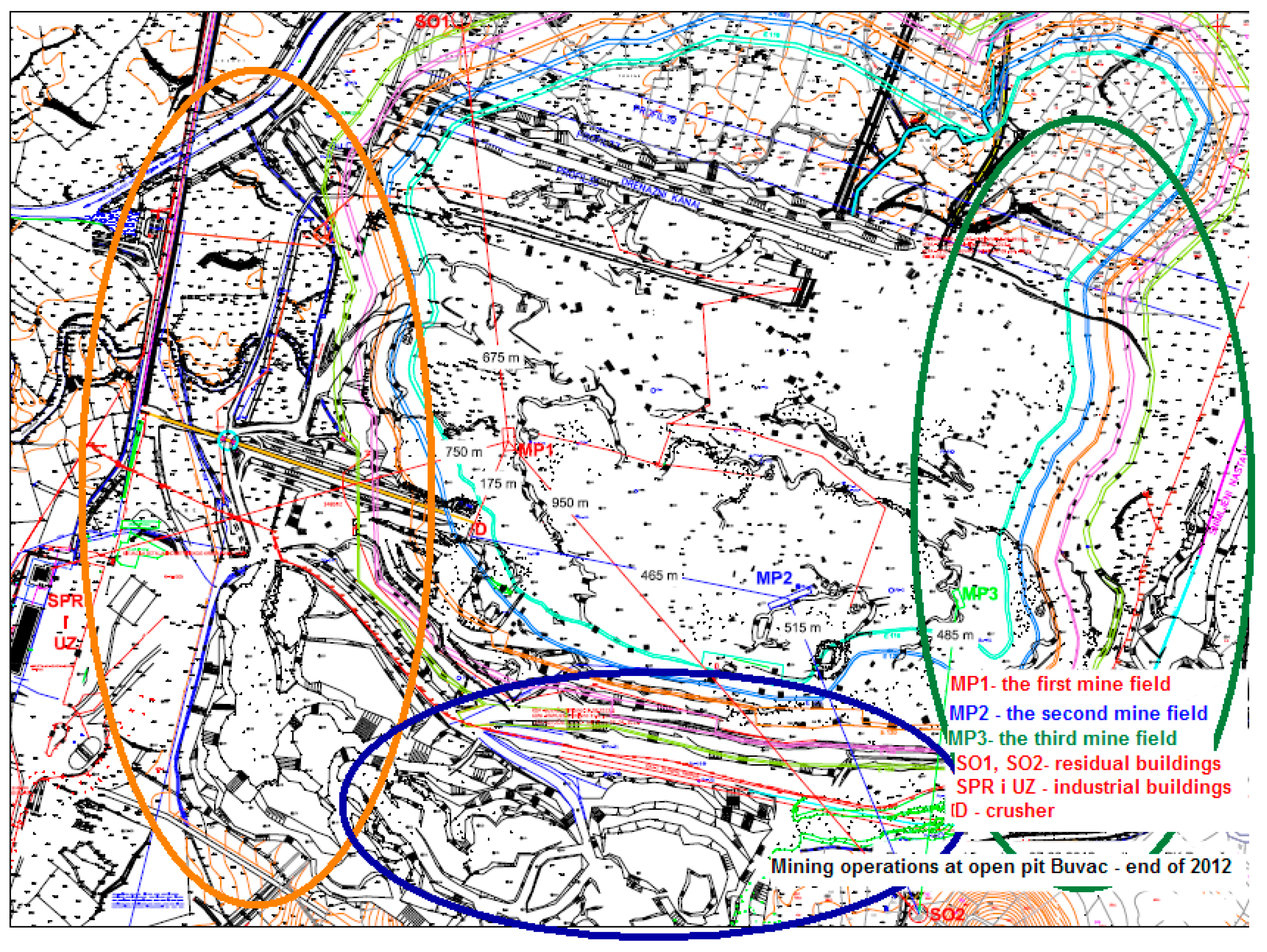
A graphical display of the minefields and position of objects that can be exposed to the negative seismic effects is shown on the map in Figure 2 [22].
3.1. Determination of the Allowed Explosives Quantity
During planning of drilling and blasting it is possible to calculate allowed quantity based on known-defined distances with usage of above mentioned mathematical dependence Equation (6) (Table 2).
With usage of allowed vibration velocities, based on safety criteria we obtain explosive quantities with allowed seismic influences on endangered objects at “Buvač” open pit. Based on the map (Figure 2) and the position of surrounding industrial, residential and other objects in relation to the potentially closest blasting fields, the distances are defined. Besides that based on past experiences and designed blasting parameters on an open pit mine, a maximum quantity of explosives is used in quantity up to 4000 kg of explosives. The input data used in the analysis and calculations are:
- -
- designed drilling and blasting parameters:Qhole = 156 kg/holeQmax = 4000 kg
- -
- The determined distances by graphical maps:Distance of the nearest minefield in the southwestern zone from an industrial facility—crusher (MP1): 175 mDistance of the nearest minefield in the southwestern zone from residential object SO1 (MP1): 675 mDistance of the nearest minefield in the southwestern zone from residential object SO2 (MP1): 950 mDistance of the nearest minefield in the southwestern zone of industrial facilities—building SPR and administrative building UZ (MP1): 750 mDistance of the nearest minefield in the central southern zone from an industrial facility—crusher (MP2): 465 mDistance of the nearest minefield in the central southern zone from residential object SO2 (MP2): 515 mDistance of the nearest minefield in the south-eastern zone from residential object SO3 (MP3): 485 m
Analysis and calculation were conducted based on the mentioned safety standards and the results are shown in Table 2.
3.2. Determination of Safety Distances in Relation to a Defined Quantity of Explosives
Based on previous experiences and parameters at the Omarska mine, the maximum used explosive quantity is up to 4000 kg so far, and the explosives quantity per hole is from 117 to 156 kg [21,22].
Based on these data the required minimum safe distance was calculated, where blasting with such quantities of explosives per hole could be done. The results are shown in Table 3. This leads to the conclusion that it is necessary to make a continuous control of the explosives quantity in simultaneous ignition for reducing the seismically-negative effects to the allowable measures on residential buildings and ground vibrations.
From Table 3 shaded and bold values represent critical distances:
- -
- In the southwestern zone, according to used/designed explosive quantities, the endangered object is a crusher according to all standards of safety criteria, and residential buildings according to DIN 4150 III standard.
- -
- In the central southern zone, according to used/designed explosive quantities, endangered facilities are residential buildings according to the standards DIN 4150 III and SN 640312. The industrial facility (crusher) is not compromised based on any criteria.
- -
- In the southeastern zone, according to used/designed explosive quantities, residential buildings are endangered based on the standards DIN 4150 III and SN 640312.
3.3. Measuring of Ground Vibrations—Monitoring of Negative Seismic Impacts by Drilling and Blasting
The results of ground vibrations measurements on the “Buvač” open pit as verification of the above calculated parameters are given in Table 4. Monitoring of negative seismic effects during drilling and blasting on the “Buvač” open pit was performed so that the seismograph is placed constantly near residential object SO1 in the southern zone of the open pit (Figure 2). Table 4 shows that the parameters in the text shown above were verified by field measurements [23].
4. Discussion
Based on the results shown in Table 2 and Table 3 it is possible to notice certain zones of conducting of drilling and blasting works in which the projected quantities of explosives need to be corrected, not to have excessive unwanted seismic impacts on industrial and residential buildings in the zone of the “Buvač” open pit.
By controlling the allowed quantities based on known distances from a few endangered objects, it is evident that:
- -
- Residential buildings are endangered if the blasting is carried out in field MP1 by the designed parameters according to the standards and allowed ground vibrations of DIN 4150 III, SN 640312, and USBM RI8507. It is necessary to additionally delay and split the explosive charge in drill holes.
- -
- According to the other defined distances in other analysed blasting zones (MP2 and MP3), the objects are not endangered, so even delaying can be placed on two or more drill holes.
If we look at the results of the performed analysis based on the known-designed explosives quantity in the blasting field meant for one hole, it can be concluded that by using an anticipated explosive quantity an industrial object-crusher is endangered by virtually all criteria and almost all blasting zones (except American standard safety criteria). Residential buildings are endangered according to the standards of SN 640312 and DIN 4150 III, as well as the criteria GOST 6249-52, regardless of the blasting zone on the open pit. This leads to the conclusion that it is necessary to reduce the explosives quantity by simultaneous ignition, or use additional delays to achieve permitted levels of negative seismic effects on the residential building and ground vibrations.
This paper presents one of the methods of mathematical modelling defining where the utilization of different safety criteria can be identified, allowing explosive quantities in simultaneous blasting based on known distances between the place of blasting and endangered objects. It is possible to define allowed distances if drilling and blasting works are organized according to the designed or planned explosive quantity.
The necessary number of delays were analysed in order to define the maximum allowed quantity of explosives according to other designed drilling and blasting parameters (drilling diameter, blasting design, minefield geometry, etc.).
It is certainly possible to change the permissible explosive quantity for simultaneous blasting and change the drilling diameter, type of explosive, minefield geometry, and other parameters, but this was not the subject of this analysis and work.
5. Conclusions
Monitoring and analysis of the negative seismic effects to the surrounding objects is necessary for protection at the specific areas of blasting operations. These areas are changeable in time and space with the development and progress of mining operations, and it is necessary to adjust the explosive quantities and the quantity allowed during simultaneous ignition.
In this way the organization of blasting operations can be successively changed in space and time, by performing of blasting operation at a lower intensity and frequency with a reduction of the negative effects to the surrounding buildings at the mine (residential, industrial, infrastructural, etc.). At the same time, within zones with a higher risk of creating intolerable negative seismic effects, drilling and blasting parameters could be corrected in terms of the use of smaller explosive quantities, and using more millisecond delayers to satisfy all of the safety standards for this technological phase.
By creating an analysis results and calculations model, all drilling and mining parameters for each specific case or mine can be defined in space and time, whereby the optimum and safely-verified quantities of explosives that can be used or activated simultaneously are calculated, as shown in this work on the “Buvač” open pit case.
From the results of the calculation and modelling of security zones in time and space is visible that it is necessary to organize drilling and blasting works with smaller quantities, which is evident from the monitoring results conducted in 2013 (reduced quantities of explosives that were used have much better results).
In higher-risk zones, it is necessary to use smaller quantities of explosives and perform additional “sharing” of explosive quantity used per blasting hole in order to meet all of the safety standards for this technological phase. Another solution would be the new design of the diameter of the drilling, the blasting design, and quantity of explosives per hole, etc.
In this manner, for any zone or space in the open pit it is possible to define the allowed explosive quantities or minimum safety distances for a certain explosive quantity when performing drilling and blasting works according to the designed drilling and blasting parameters.
Acknowledgments
The analyses and results published in this paper are the result of the work of the Prijedor Mining Faculty professors with students through final works and seminar papers of Master’s studies. Thus, there was no financing during the performance of the works and analyses, nor were funds required from the sponsors to publish this work. On this occasion, we express our gratitude to colleagues, and engineers in AMP, on the provided results of seismograph measurements made during the regular monitoring of the seismic effects of drilling and blasting operations. We would like also to show gratitude to the company ArcelorMittal Prijedor for providing part of the displayed input data, but also for great support in theoretical and practical education and logistics through the teaching processes with students of the faculty.
Author Contributions
Vladimir Malbašić performed the synthesis of the results achieved so far, and then elaborated the data and performed a calculative analysis, while Lazar Stojanović is a lecturer in the topic “drilling and blasting” in the first study cycle and the topic of Master’s studies on “special methods of mining and demolition of objects”, and he also participated in the writing of the paper.
Conflicts of Interest
The authors declare no conflict of interest.
References
- Office of Surface Mining Reclamation and Enforcement. OSM Blasting Training Modules. 2004. Available online: https://www.osmre.gov/resources/blasting/btm/Module8.pdf (accessed on 14 May 2017).
- Purtić, N. Seizmičko Dejstvo Eksplozije” u Udžbeniku “Bušenje i Miniranje, 1st ed.; (Seismic Action of the Explosion. Drilling and blasting, 1st ed.); Faculty of Mining and Geology: Belgrade, Serbia, 1991; pp. 234–243. [Google Scholar]
- Zhong, G.; Li, J.; Zhao, K. Structural safety criteria for blasting vibration based on wavelet packet energy spectra. Min. Sci. Technol. 2011, 21, 35–40. [Google Scholar] [CrossRef]
- Stagg, M.S.; Siskind, D.E. Effects of Blast Vibration on Construction Material Cracking in Residential Structures; Bureau of Mines Technology Transfer Seminar: Chicago, MI, USA, 1987; p. 43.
- Siskind, D.E.; Stagg, M.S. Blast Vibration Measurements Near Structures; Bureau of Mines Technology Transfer Seminar: Chicago, MI, USA, 1987; pp. 46–50.
- Hustrulid, W.A. Blasting Principles for Open Pit Mining, 1st ed.; CRC Press: Rotterdam, The Netherlands, 1999; Volume 2. [Google Scholar]
- Malbašić, V.; Stojanović, L. Determination of Seismic Safety Zones during the Surface Mining Operation Development in the Case of Open Pit “Buvač”. In Proceedings of the 6th International Symposium MEP 17, Vrdnik, Serbia, 21–24 June 2017; pp. 138–144. [Google Scholar]
- Körmendi, A.; Bodoky, T.; Hrmann, L.; Dianiska, L.; Kālman, T. Seismic Measurements for Safety in Mines. In Proceedings of the 45th Meeting of the EAEG, Oslo, Norway, 14–17 June 1983. [Google Scholar]
- Maxwell, S.C.; Young, R.P. Seismic imaging of blast damage. Int. J. Rock Mech. Min. Sci. Geomech. Abstr. 1993, 30, 1435–1440. [Google Scholar] [CrossRef]
- Malbašić, V.; Čelebić, M. Determination of Safety Zones by Drilling and Blasting to Maximal Possible Structure Protection on Quarry, Ljubačevo Near Banja Luka Sample; Archives for Technical Science: Bijeljina, Republica Srpska, 2011; pp. 119–132.
- Kopp, J.W. Initiation Timing Influence on Ground Vibration and Airblast; Bureau of Mines Technology Transfer Seminar: Chicago, MI, USA, 1987; pp. 51–59.
- Yu, S. Safety of Ground Motion in Engineering Blasting. 1995. Available online: http://en.cnki.com.cn/Article_en/CJFDTotal-GCBP502.012.htm (accessed on 23 November 2017).
- Lutovac, S.; Medenica, D.; Glušcevic, B.; Tokalic, R.; Beljic, C. Some models for determination of parameters of the soil oscillation law during blasting operations. Energies 2016, 9, 617. [Google Scholar] [CrossRef]
- Arsenović, Ž. Study on the Negative Environmental Effects of Blasting Technology on Open Pit “Dubokipotok-Bijela Rijeka” and Negative Efectson Buildings in Gravitational Urbanism Zones of the Settlement Duboki potok and Bjelave at the Quarry Exploitation Field; CTU Ipkin: Bijeljina, Republica Srpska, 2009; pp. 15–18. [Google Scholar]
- Ebrahimi, F.F.; Mokammad, F.; Hamid, A.M. Simultaneous investigation of blast induced ground vibration and airblast effects on safety level of structures and human in surface blasting. Int. J. Min. Sci. Technol. 2014, 24, 663–669. [Google Scholar]
- Phifer, M.; Hem, P. Blasting, TechnoMine-Mining Technologies. March 2012. Available online: http://technology.infomine.com/reviews/Blasting (accessed on 12 December 2017).
- SN 640312. Auszug Norm Gebäudeschäden Durch Vibrationen. Available online: https://infostore.saiglobal.com/en-au/Standards/SN-640312-2013-1723806/ (accessed on 12 March 2017).
- DIN 4150 III. Structural Vibration—Effects of Vibration on Structures. Available online: https://infostore.saiglobal.com/en-gb/Standards/DIN-4150-3-1999-02--515801/ (accessed on 20 April 2017).
- WAC 296-52-67065/USBM RI8507. Vibration and Damage Control. Available online: https://app.leg.wa.gov/wac/default.aspx?cite=296-52-67065 (accessed on 10 March 2017).
- GOST 6249-52—Scale for Determining the Strength of the Earthquake in the Range from 6 to 9 Points (Scale for Determining the Strength of the Earthquake in the Range from 6 to 9 Points). Available online: http://internet-law.ru/gosts/gost/46361/ (accessed on 10 February 2017). (In Russian).
- Malbašić, V. At All Main Mining Project for Exploitation of Deposit "Omarska" Locality "Buvač”; Institute of mining Prijedor and Faculty of Mining and Geology Belgrade: Belgrade, Serbia, 2007.
- Jovanović, N. Definisanje Sigurnosnih Zona Pri Miniranju na PK Buvač; Graduated work Faculty of mining Prijedor University Banja Luka: Belgrade, Serbia, 2012. [Google Scholar]
- Documentation-logs of Mining and Seismic Measurements on Open Pit Buvač Made by Employees in AMP; ArcelorMittal Rudnici: Prijedor, Bosnia and Herzegovina, 2013.
Figure 1.
(a) Spreading of seismic and air waves during blasting; and (b) the scheme of energy balance during blasting.
Figure 1.
(a) Spreading of seismic and air waves during blasting; and (b) the scheme of energy balance during blasting.

Figure 2.
Graphical display of the objects’ positions and the potentially closest minefield.


Table 1.
Summary of drilling and blasting parameters with the use of rotary percussive drills at the “Buvač” open pit [7,21].
| Drilling and Blasting Parameters | The Unit of Measure | Blasting with a 150–170 mm Hole Diameter of, Bench Height H = 10 m | |||
|---|---|---|---|---|---|
| Main Loading | kg | AN-FO | Emulsion | Plastic Explosives | Plastic Explosives |
| Support Loading | kg | Emulsion | AN-FO | AN-FO | Powder Explosive |
| W | m | 5.50 | 5.00 | 5.50 | 5.50 |
| a | m | 5.50 | 5.50 | 6.00 | 5.60 |
| b | m | 5.50 | 5.50 | 5.50 | 5.50 |
| m | 1.00 | 1.10 | 1.10 | 1.10 | |
| Ldrill hole | m | 11.40 | 11.50 | 11.65 | 11.65 |
| Lpitting | m | 1.40 | 1.50 | 1.65 | 1.65 |
| Lmain load. | m | 7.40 | 4.03 | 4.22 | 4.28 |
| Lsupp.load. | m | - | 3.47 | 3.43 | 3.39 |
| Lcork | m | 4.00 | 4.00 | 4.00 | 4.00 |
| Qmain | kg | 138.00 | 72.00 | 81.25 | 82.37 |
| Qsupp. | kg | 18.00 | 45.00 | 44.18 | 55.42 |
| Qtotal | kg | 156.00 | 117.00 | 125.43 | 137.79 |
| Delay | ms | 40 | 40 | 40 | 40 |
| Quantity | t | 726 | 660 | 792 | 792 |
| q | kg/t | 0.215 | 0.177 | 0.160 | 0.174 |
| Capacity | t/m | 63.68 | 57.40 | 67.68 | 67.68 |
Table 2.
Restatement of the calculation results for the allowed explosive quantities simultaneously ignited by the positions and distances between vulnerable objects and the potentially closest blasting fields [23].
Table 2.
Restatement of the calculation results for the allowed explosive quantities simultaneously ignited by the positions and distances between vulnerable objects and the potentially closest blasting fields [23].
| Standard Calculated Explosive Quantity, kg | Distance | Qhole, kg Q field | ||||||
|---|---|---|---|---|---|---|---|---|
| MP1 | MP2 | MP3 | ||||||
| 175 | 675 | 750 | 950 | 465 | 515 | 485 | 117–156 4000 | |
| SN 640312 industrial buildings | 272 | 15,625 | 21,433 | 43,560 | 7095 | 9638 | 117–156 4000 | |
| SN 640312 residential buildings | 84 | 4805 | 6592 | 13,2396 | 2155 | 2928 | 2079 | 117–156 4000 |
| DIN 4150 III industrial buildings | 237 | 7095 | 117–156 4000 | |||||
| DIN 4150 III residential buildings | 63 | 3610 | 4593 | 10,064 | 1695 | 2303 | 1596 | 117–156 4000 |
| USBM RI8507 | 47.5 | 706 | 872 | 1398 | 335 | 411 | 365 | 117–156 4000 |
| GOST 6249-52 | 781 | 44,838 | 61,507 | 12,500 | 20,465 | 27,082 | 19,562 | 117–156 4000 |
Note: Table 2 shows that the distance of 175 m is critical to all standards and that all facilities are endangered by using the predicted/designed explosive quantity and that residence objects are endangered in the central southern zone and the southeastern zone (shaded quantities) according to the standards SN 640312 and DIN 4150 III. Shaded and bold quantities in the table indicate that, according to the standards of SN 640312 and DIN 4150 III, it is necessary to install additional delays in the charge construction of blasting hole with distance of 175 m.
Table 3.
Summary of the calculation results for safety distances related to the designed and used explosive quantities [7].
Table 3.
Summary of the calculation results for safety distances related to the designed and used explosive quantities [7].
| Buildings | GOST 6249-52 | SN 640312 | DIN 4150 III | USBM RI8507 | ||||
|---|---|---|---|---|---|---|---|---|
| Lmeas | Lcalc | Lmeas | Lcalc | Lmeas | Lcalc | Lmeas | Lcalcul | |
| MP1 | ||||||||
| Industrial buildings and crusher | 175 | 302 | 175 | 429 | 175 | 429 | 175 | 1606 |
| Residential buildings | 675 | 302 | 675 | 635 | 675 | 698 | 675 | 1606 |
| 950 | 302 | 950 | 635 | 950 | 698 | 950 | 1606 | |
| Administrative building and workshop | 750 | 302 | 750 | 635 | 750 | 429 | 750 | 1606 |
| MP2 | ||||||||
| Industrial buildings and crusher | 465 | 270 | 465 | 384 | 465 | 384 | 465 | 1606 |
| Residential buildings | 515 | 270 | 515 | 571 | 515 | 619 | 515 | 1606 |
| MP3 | ||||||||
| Residential buildings | 485 | 286 | 485 | 603 | 485 | 619 | 485 | 1606 |
Table 4.
Results of measurements of ground vibrations of the “Buvač” open pit as verification of the above calculated parameters.
Table 4.
Results of measurements of ground vibrations of the “Buvač” open pit as verification of the above calculated parameters.
| Bench | Date | Explosive Quantity (kg) | Distance (m) | PPV Transversal (mm/s) | PPV Vertical (mm/s) | PPV Longitude (mm/s) | Peak Vector Sum (mm/s) |
|---|---|---|---|---|---|---|---|
| East 130 | 06.10.2013. | Qexp = 891 Qsim = 224–334 | Blasting field to residential building SO1 510 | 0.889 | 0.0635 | 0.318 | 0.889 |
| West 130 | 10.10.2013. | Qexp = 1479 Qsim = 224–672 | Blasting field to residential building SO1 740 | 0.445 | 0.0635 | 1.08 | 1.11 |
| East 130 | 26.10.2013. | Qexp = 912 Qsim = 224–344 | Blasting field to residential building SO1 530 | 0.318 | 0.0635 | 0.762 | 0.826 |
© 2018 by the authors. Licensee MDPI, Basel, Switzerland. This article is an open access article distributed under the terms and conditions of the Creative Commons Attribution (CC BY) license (http://creativecommons.org/licenses/by/4.0/).
Share and Cite
MDPI and ACS Style
Malbasic, V.; Stojanovic, L. Determination of Seismic Safety Zones during the Surface Mining Operation Development in the Case of the “Buvač” Open Pit. Minerals 2018, 8, 71. https://doi.org/10.3390/min8020071
AMA Style
Malbasic V, Stojanovic L. Determination of Seismic Safety Zones during the Surface Mining Operation Development in the Case of the “Buvač” Open Pit. Minerals. 2018; 8(2):71. https://doi.org/10.3390/min8020071
Chicago/Turabian StyleMalbasic, Vladimir, and Lazar Stojanovic. 2018. "Determination of Seismic Safety Zones during the Surface Mining Operation Development in the Case of the “Buvač” Open Pit" Minerals 8, no. 2: 71. https://doi.org/10.3390/min8020071
Note that from the first issue of 2016, this journal uses article numbers instead of page numbers. See further details here.