A Preliminary Investigation into Separating Performance and Magnetic Field Characteristic Analysis Based on a Novel Matrix


School of Resources and Civil Engineering, Northeastern University, Shenyang 110819, China
*
Author to whom correspondence should be addressed.
Minerals 2018, 8(3), 94; https://doi.org/10.3390/min8030094
Submission received: 1 January 2018
/
Revised: 31 January 2018
/
Accepted: 26 February 2018
/
Published: 2 March 2018
(This article belongs to the Special Issue Sustainable Mineral Processing Technologies)
Abstract
:The matrix is the agglomeration carrier of magnetic mineral particles in high-gradient magnetic separation (HGMS). Its structural parameters have a great influence on the distribution of the magnetic field in the separation space, and therefore affect the separation effect. This paper introduces a novel matrix called a screw thread rod matrix, which has the dual advantages of the rod matrix and the grooved magnetic plate, i.e., the advantages of better slurry fluidity through the matrix and higher magnetic field gradient at the sharp corners. This research on the novel matrix was performed from the following three aspects: the description of components of the matrix, the effect of structural parameters of the matrix on separation performance of fine hematite ore tailings in Northeast China, and the numerical analysis of the magnetic induction properties of different kinds of magnetic matrices based on three-dimensional structural characteristics. Compared with the smooth rod matrix, the proposed screw thread rod matrix enhances the inhomogeneity of the axial magnetic induction intensity on the surface of the matrix. Accordingly, the recovery of fine-grained iron minerals is improved through the resulting combined effect of the radial curvature of the rod and the inhomogeneous magnetic field in the axial direction. Furthermore, the best moderate distance between equidistant ring-shaped bulges (ERB) as well as the best column gap between adjacent rod elements were determined, respectively.
1. Introduction
The High-gradient magnetic separation (HGMS) technique is widely used in industrial fields including the sufficient recovery of weakly magnetic iron mineral, kaolin clay beneficiation, water treatment, coal desulfurization, and catalytic processes, etc. [1,2,3,4,5]. It has become a powerful approach, especially in the manipulation of micro-fine weakly magnetic mineral particles. Due to the high gradient around the matrix in the presence of a strong magnetic field, the magnetic attraction imposed on weakly magnetic mineral particles is far greater than the counter-acting force from swift-flowing pulp [6]. When mineral grains that present weak magnetic or antiferromagnetic responses are close to the surface of magnetized rod matrices, the magnetic driving force will increase sufficiently to enable magnetic particles to be captured from a carrier fluid [7]. Therefore, both how to improve the capture efficiency of feebly magnetic mineral granules and how to enhance the magnetic force being imposed on the weakly magnetic mineral particles become the key focuses of high gradient magnetic separation in the processing of iron ore.
Equation (1) gives the expression of magnetic force which acts on the magnetizable mineral particle in the swift-flowing pulp [8]. B is the magnitude of magnetic induction intensity at a particle location, B is the magnitude of the gradient, κp and κf are the volume magnetic susceptibilities of particle and fluid (water), separately, Vp is the magnetizable particle volume, and μ0 is the magnetic permeability of vacuum.
As shown in Equation (1), there are various ways to achieve the desired beneficiation effect in the process of high gradient magnetic separation, such as intensifying magnetic induction intensity, improving magnetic field gradient, and strengthening the induction of hydrophobic flocculation of extremely fine weakly magnetic mineral particles to form flocculation [9,10,11,12]. The first two ways are more closely related to magnetic field distribution of separation space and the latter one may be accomplished by changing the surface hydrophilic property of feebly magnetic minerals under the action of surfactants. Some basic research can be found on selective hydrophobic or magnetic flocculation [13,14,15,16,17]. However, complex procedures of forming suitable floccules make it difficult to hold steady running in the production of mineral processing. Moreover, flocculation agents may adversely affect the subsequent reverse flotation effect and the quality of the treated water in the concentrator. Therefore, more attention has been paid to the optimization of the distribution of magnetic field by means of putting matrices into a uniform background magnetic field.
Since the saturation magnetization of iron-based material is between 2 T and 2.5 T, the conventional HGMS magnetic circuit using the material as iron yoke can hardly generate a background magnetic field of 2 T or more in the sorting space [6,18,19]. Therefore, a larger magnetic force can hardly be generated by improving background magnetic field intensity without superconducting magnetic circuits [20,21,22]. However, the world’s iron ore reserves are huge and the prices are far below those of precious metals such as gold. It is unacceptable to use superconducting magnetic separation in the preparation of fine hematite concentrate in iron ore concentrators under the current tech-economic conditions [23,24,25]. Generally, the separation space is filled with a lot of matrix rod elements as secondary poles in ordered arrangement [26]. To improve the recovery effect of magnetic minerals, the method of adjusting the matrix is not only economically reasonable but also environmentally friendly. Thus, it is a good alternative to add a magnetic field gradient followed by enlargement of the magnetic force by adjusting magnetic field distribution around the matrix. This work focuses on the effect of the matrix parameters on the separation results for micro-fine hematite particles. The magnetic flux density distribution character of a novel matrix was investigated and is discussed in great detail. The major contributions of this paper are as follows: First, the way to enhance the recovery of fine-grained iron ore by changing the structure of the medium was put forward. Second, a new type of matrix was designed and the optimum structural parameters for the separation determined. Finally, the recovery of the iron tailings from Dong’anshan was shown to be improved.
2. Experimental
2.1. The Screw Thread Rod Matrix
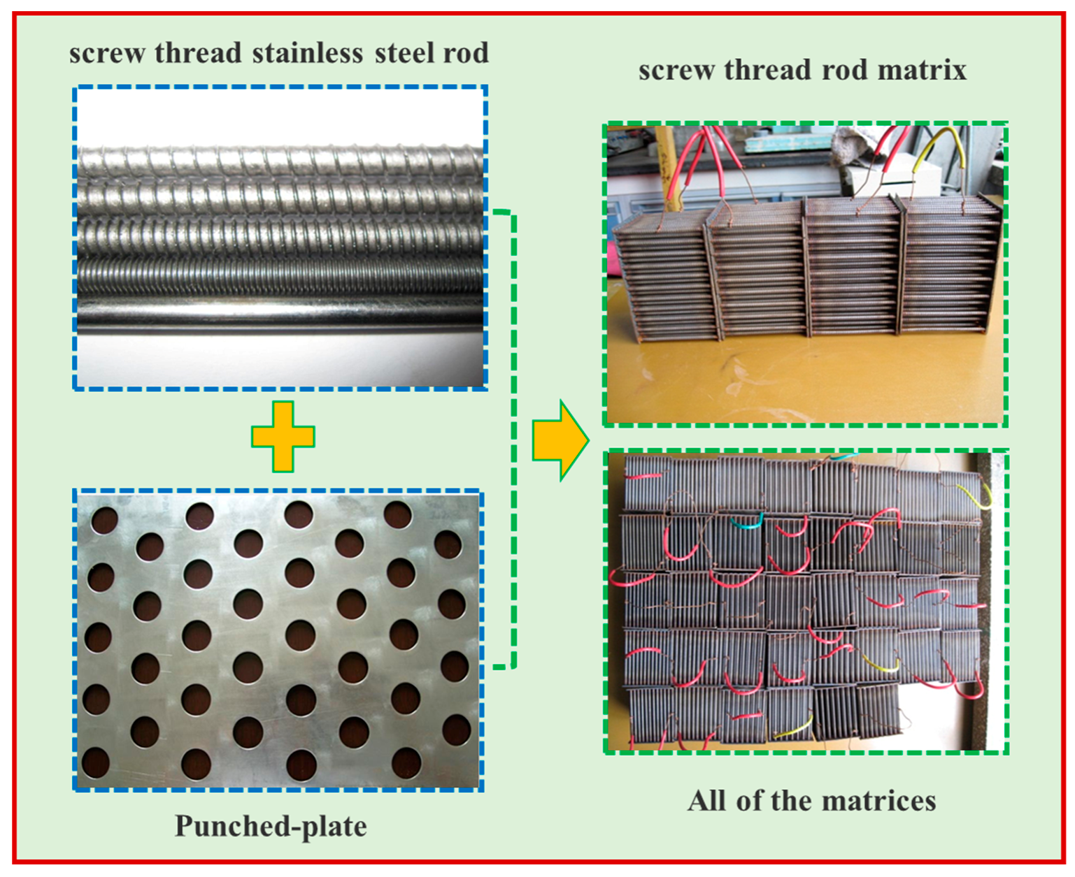
As Figure 1 shows, the screw thread rod matrix is composed of many screw thread stainless steel rods in an oriented arrangement. Apart from possessing the advantage of the conventional rod matrix, the design of the screw thread generates an axial magnetic gradient along the rod, strengthening the inhomogeneity of the induced magnetic field around the matrix. The screw thread stainless steel rod, as the basic unit of the new type of matrix, consists of a cylinder and lots of equidistant ring-shaped bulges (ERB). The material of the matrix rod is stainless steel (SUS430) with high permeability. The stainless steel (SUS304) is used for the punched-plates fixing rod-group. Rods are welded with double punched-plates into a single system on an interlaced arrangement of adjoining rows. The influence of the rod diameter has drawn much attention from global researchers. Beneficial results can be found in former research works [27,28,29,30]. Hence, this paper did not dig deeply into the effect of rod diameter. Stainless steel rod with 3 mm diameter has been widely used in processing of refractory hematite ore [19]. In view of the above-mentioned facts, 3 mm fixed rod diameter was used in this study.
2.2. A Horizontal Magnetic Field Orientation HGMS Separator and Its Principle
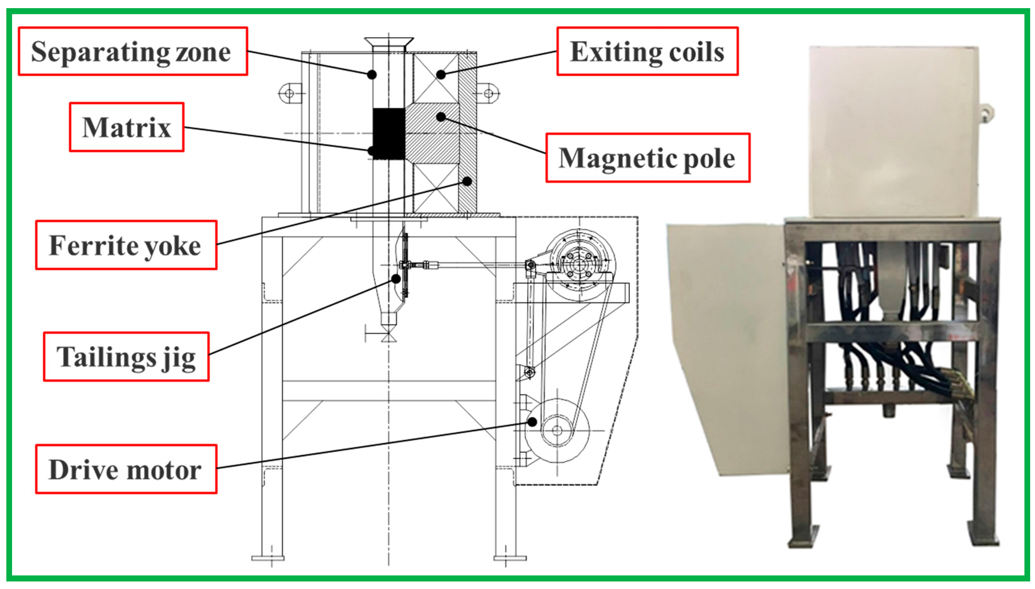
A pilot pulsating HGMS separator was used to conduct the physical testing on different matrix parameters, as shown in Figure 2. The C-dipole configuration was employed in the equipment which consists of a combination of ferrite yoke, magnetic poles, exiting coils, separating zone, matrix, tailings jig, and a drive motor. The major difference from the typical mode of a cyclic KolmMarston HGMS system is that the pulp flow direction of the horizontal magnetic field orientation HGMS separator is perpendicular to the magnetic force line in the air gap between the magnetic poles [18]. In addition, the magnetic particles aggregation regions on the surface of the matrix rod in the horizontal magnetic field are located on both sides of the rod along the force lines of a magnetic field rather than along the direction of the flowing pulp.
When a direct current to the excitation coil is applied, a strong magnetic field is generated in the working gap by the iron-core electromagnet with the C-dipole configuration. The high magnetic field gradient is enhanced in the close vicinity of the rod matrix. Slurry is fed into the separation chamber evenly through the feed box. The magnetic particles are attracted onto the surface of the magnetic matrix due to the high magnetic force produced around the matrix. The tailings jig is normally adjusted for a higher pulse frequency and lower stroke. The fluid power reduces to only allow extremely weak magnetic particles and non-magnetic particles to be washed away from the matrix. The washed-away material passes through the matrix into the tailings discharge launder. The stronger magnetic particles are collected by the matrix. A cycle of HGMS is finished when the tailing pulp flowing in the tailings collecting barrel is replaced by water. The tailings collecting barrel will then be settled replacing the former concentrate collecting barrel. After that, the direct current is shut off and the magnetic force is gradually reduced until sufficiently weak. The flushing water washes away the magnetic particles from the magnetic matrix assembly compartment into the concentrate collecting barrel. This effectively separates the feed into two products with different iron contents.
2.3. Sample
The fine hematite ore tailings used in this investigation were taken from Dong Anshan beneficiation plant in Liaoning province, China. The sample has an iron grade of 14.30%, and consists of iron-bearing minerals, large amounts of quartz, and other silicate minerals. The iron-bearing minerals are mainly composed of hematite and siderite in the ratio of 8:1. The magnetic iron content in the sample is very low due to former treatment by high intensity magnetic separation in the mineral processing production. The −43 μm size fraction accounts for 75.26% of the overall particle size fractions. However, the iron content of the −43 μm size fraction accounted for 95.08% of the total iron in the material.
2.4. The Physical Testing Procedures and Conditions
The specified matrix is put into the separating chamber and then the separating zone is filled with flowing water. The material and running water are mixed together with a mass ratio of 4:1 in a stirred tank for 10 min before each unit experiment. After completion of setting the exciting current producing magnetic field, the feed stream containing weak magnetic minerals in the form of slurry is evenly poured into the separating zone within 15 s. It is worth mentioning that the matrix should be entirely submerged in the flowing water during the whole high gradient magnetic separation so that the pulsating energy coming from the reciprocate motion of the tailings jig can be transmitted to the separating zone [27]. The magnetic particles in this feed stream are captured on the surface of the magnetized matrix rods, while the non-magnetic particles follow the flowing slurry into the tailings collecting barrel. Finally, the intensity of the magnetic field is reduced to zero and the magnetic particles are easily washed from the matrix by the separate flushing water. Based on the above procedures, the effects of the following main structural parameters of screw thread rod matrix were investigated: (1) the distance parameter between ERB on the surface of the screw thread rod; (2) the column gap parameter between adjacent rod elements on the separation performance of HGMS in retrieving fine hematite. The optimal operating parameters of HGMS were appropriately determined beforehand and are listed in Table 1.
2.5. Evaluation Methods of Separation Performance
The separation performance was closely related to the iron concentrate grade, the iron recovery, and the separation efficiency. Iron recovery () and separation efficiency () were calculated according to Equations (2) and (3), respectively:
where is the feed grade, is the concentrate grade, and is the maximum Fe grade of hematite (70% Fe in Fe2O3).
3. Results and Discussion
3.1. Influence of the Distance between ERB on Separation Performance
According to the principle of magnetism, the appearance of magnetized metal wire has a great impact on the surrounding magnetic field distribution as well as on the capture of fine-grained weakly magnetic iron minerals [30,31]. The presence of the screw thread plays a positive role in the convergence of the magnetic field lines on the surface of the matrix. Therefore, the influence of distance between ERB (p value) on the separation performance of fine hematite tailings from the Dong Anshan beneficiation plant was analyzed especially under the conditions of different column gaps of 2 mm, 3 mm, 4 mm, and 5 mm, respectively.
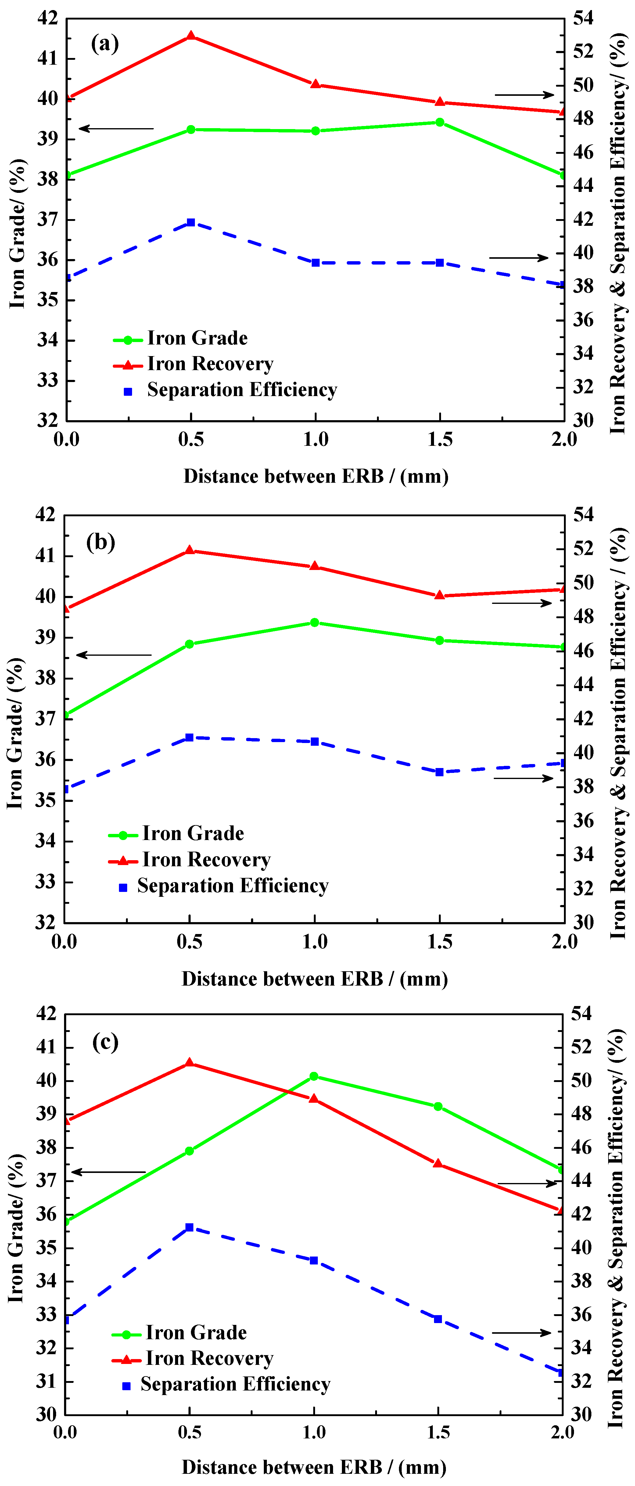
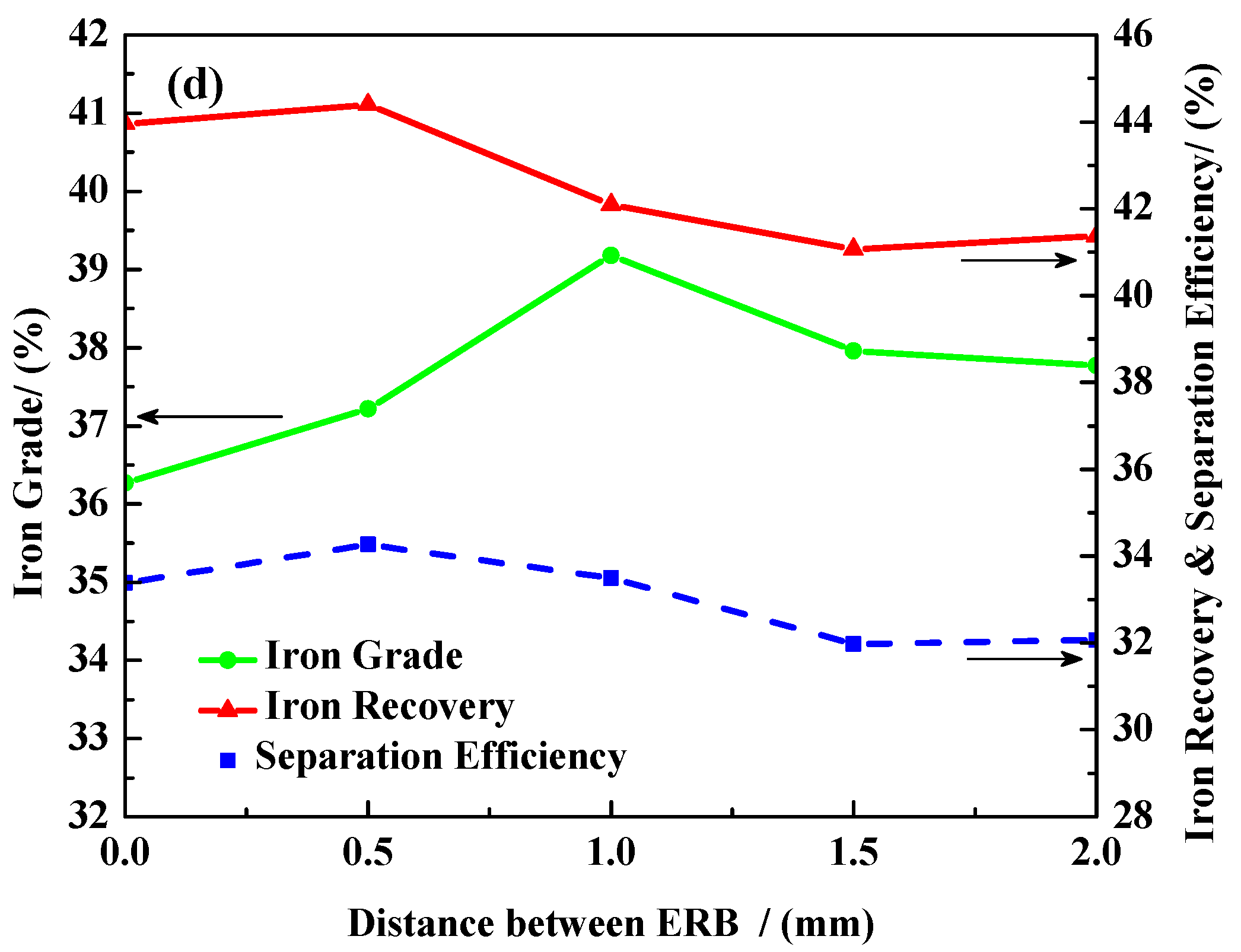
As illustrated in Figure 3, for a matrix diameter of 3.0 mm at a column gap of 2 mm, the separation efficiencies with p values of 0 mm, 0.5 mm, 1.0 mm, 1.5 mm, 2.0 mm are 38.53%, 41.84%, 39.44%, 39.20%, 38.11%, respectively. The separation efficiency increases first and then decreases at a p value greater than 0.5 mm, indicating the optimum p value is 0.5 mm. With the increase of distance between ERB (p value) from 0 mm to 2.0 mm, the trends of separation performance for different column gaps (d value) are similar. Obviously, regardless of the column gap between adjacent rod elements, the separation efficiency and iron recovery of the screw thread rod (p = 0.5 mm) are better than those of the smooth matrix rod (p = 0 mm) with 3% increase in the recoveries. Notably, the iron grade did not decline with the increase of recovery, but increased by one percent or more. Without exception, this regularity is ubiquitous for the column gap at 2 mm, 3 mm, 4 mm, and 5 mm in Figure 3. It can be found that the distance between ERB (p value) is an important variable when determining the iron recovery and the separation efficiency of the magnetic product. The reason for this phenomenon is that, due to the presence of helical protrusions, the magnetic field distribution on the surface of the rod changes significantly, which further enhances the rod’s ability to capture the magnetic particles [32]. For a better explanation of this effect, a detailed description is now made with subsequent numerical simulations.
3.2. Influence of Column Gap between Adjacent Rod Elements on the Separation Performance
When the matrix fibers are randomly deployed, the capture efficiency (recovery) of the separator is considerably weakened. Therefore, the ordered arrangement of rod units becomes common law for wet high-intensity magnetic separation [33]. The influences of rod diameter, rod gap and filling rate on the separating effect have been investigated by a previous meaningful work [28,30]. The gaps between the matrix rods consist of the row gap and the column gap. The row gap affects the layers of the matrix bed when the depth of the matrix is fixed, which in turn determines the collision probability of magnetic particles with matrix elements [6]. The column gap affects the intensity of the magnetic field in the direction of the magnetic field lines, which determines the degree of magnetic induction in the catch area. When the distance between matrix rods in the direction of the magnetic field is smaller, the filling rate of the matrix in the sorting space becomes larger. Accordingly, the magnetic induction intensity on the surface of the rod will be higher. In the case of the same matrix rod diameter, the column gap between adjacent rod elements has a greater effect on the material separating characteristics in the horizontal magnetic field. The effects are separately discussed under the conditions of different distances between ERB (p = 0, 0.5 mm, 1.0 mm, 1.5 mm, 2.0 mm).
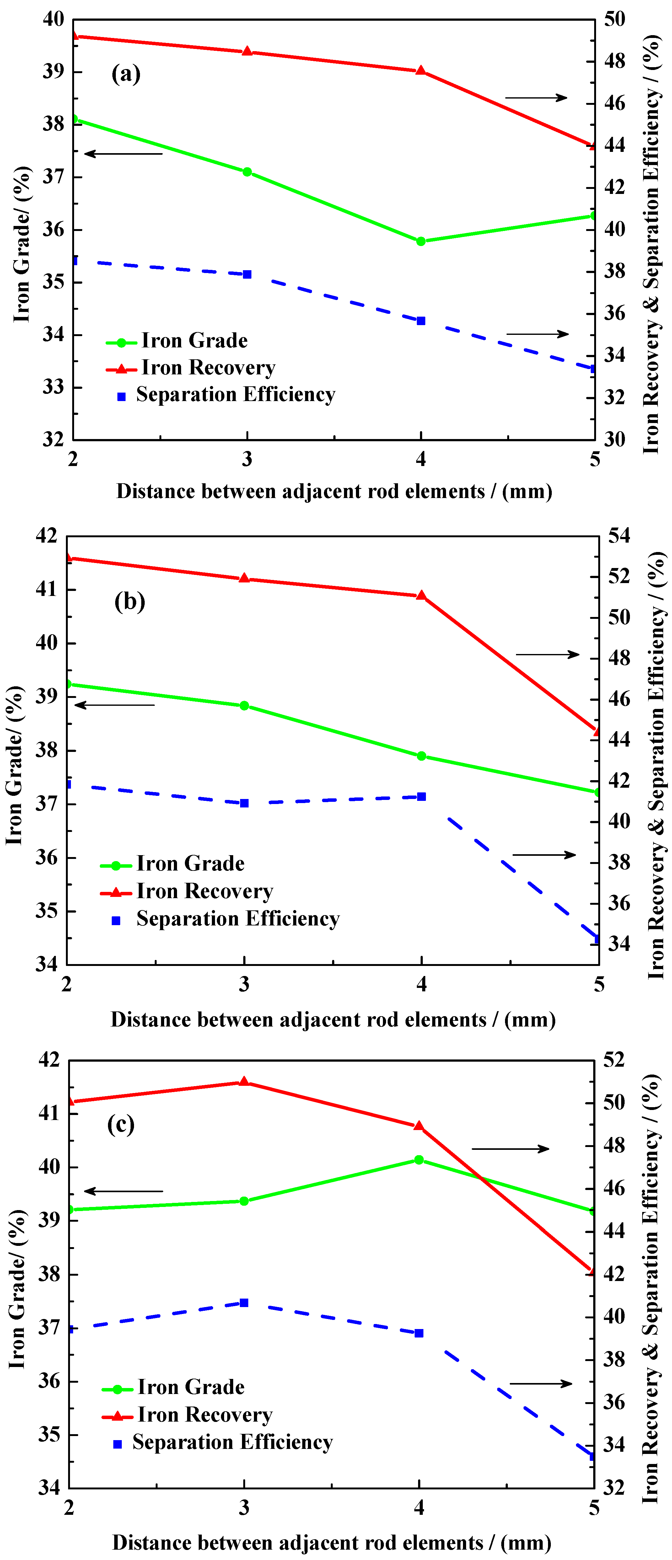
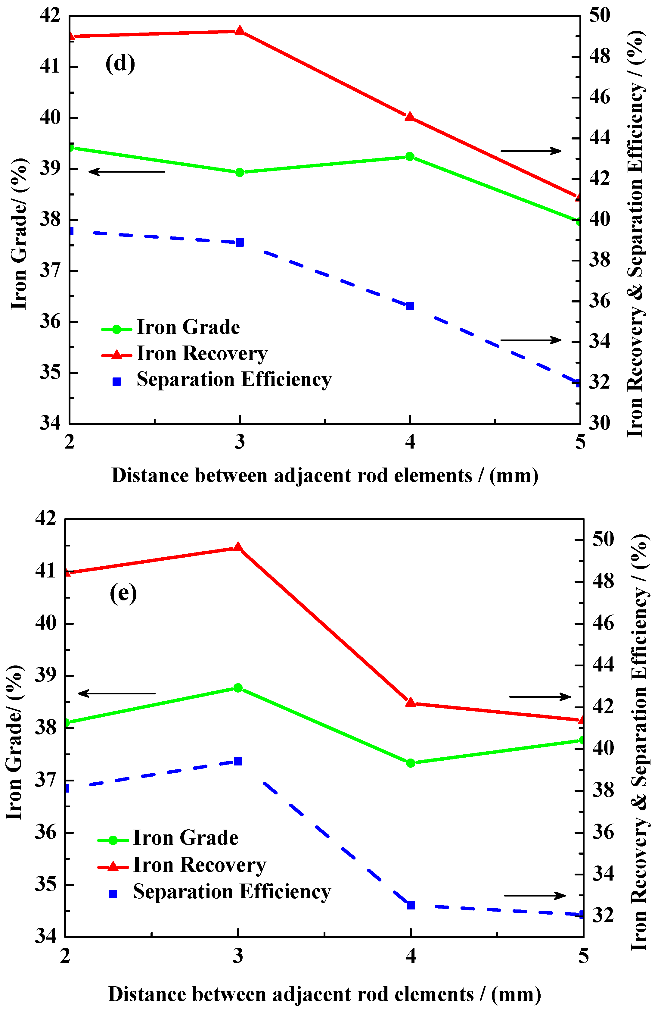
It is interesting to note from Figure 4 that the trends of separation efficiency with the increase of column gap (d value) under the condition of different distance between ERB are similar. As is shown in Figure 4a, for the smooth matrix rod (p = 0 mm), the iron recovery and the grade decrease with the increase of the d value. When the d value is 2 mm, iron recovery is 49.21% and the grade is 38.11% of magnetic product. For the screw thread rod (p = 0.5 mm), the best separation effect corresponds to a d value of 2 mm with an iron grade of 39.24% and a recovery of 52.94%. At the same time, the recovery and the grade of iron decrease notably as the column gap increases in Figure 4b. For the other three screw thread rods (p = 1.0 mm, p = 1.5 mm and p = 2.0 mm) in Figure 4c–e, the results at d = 2 mm and d = 3 mm are found to be very similar. However, when the d value increases to 4 mm or 5 mm, the iron recovery is even smaller than the index of d = 2 mm or d = 3 mm. Above all, no matter whether for the screw thread rods or for the smooth matrix rods, the smaller column gap gives a better recovery effect in the case of no clogging of matrices. The interaction between the matrix units enhances the magnetic field distribution in the separating zone, which explains why the selection effect is improved.
4. Numerical Analysis of Magnetic Field Distribution Based on Matrix Parameters
Apparently, it is significant to examine the effect of parameters of the screw thread rod matrix on the static spatial magnetic field for the investigation and analysis of the improvement of separation performance. However, there are some difficulties in the accurate measurement of the magnetic field distribution by adopting numerical type Gauss account (i.e., Hall effect) due to the narrow spaces inside a matrix. So far, the finite element method has been used extensively to solve all sorts of problems of electromagnetic field governed by partial differential equations [34,35]. In this work, the commercially available analysis tool of finite element method (FEM), Ansoft Maxwell 3D was used to understand the effects of different matrices on the magnetic field distribution. In this way, the physical testing workloads and material costs will be reduced significantly.
4.1. Establishment and Optimization of the Simulation Model
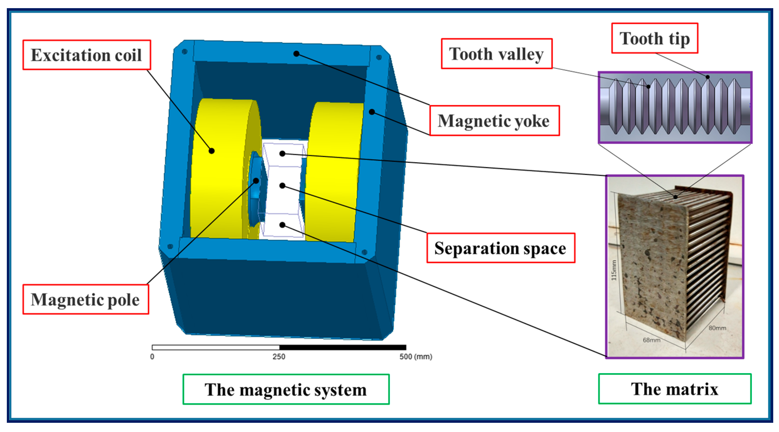
It is worth noting that three-dimensional magnetic field distribution of the actual matrix is so complex that it not only can bring about a significant amount of calculation work but it is also difficult for post-processing due to the cylindrical spiral. Therefore, the actual model was simplified in that the helical saw-toothed bulges on the surface of the matrix rod were adjusted to be perpendicular to the rod axis according to the theory of geometric similarity. A sample model of the novel matrix rod is shown in Figure 5. The C-dipole configuration model was built and each component of the magnet assembly is indicated, as shown in Figure 6. The current source acts as a source of excitation for the three-dimensional magnetic field. The materials of the model components are listed in Table 2.
4.2. Governing Equations
Since the high gradient magnetic field around the matrix is a static magnetic field generated from a direct current electromagnet, a DC current solver in Maxwell 3D was employed to compute the magnetic field strength (H) and magnetic flux density (B). The three-dimensional static magnetic field was calculated by the edge method. According to Ampere’s law and the Gaussian flux law, Maxwell’s equations can be simplified into the following equations.
where B (x, y, z) is the magnetic flux density, H (x, y, z) is the magnetic field intensity, and J (x, y, z) is the current density. These three vectors are the functions of the vector of each direction, out of which B (x, y, z) can be expressed as
where Bx, By, and Bz are the scalar magnetic induction intensities in the three directions, respectively.
4.3. Mesh Generation and Defined Parameters for the Solution Process
The mesh size varies in each of the simulations depending on the model structure. In most of our simulations, the grid meshing was carried out by using the adaptive meshing function, and the meshing unit was tetrahedron. Considering the high precision of the thread structure of the magnetic adsorption, manual mesh was used to increase the mesh density for the local range of the thread structure by Loop encryption grid operation. About 100,000 tetrahedrons were used when employing an outer solution in each model mesh. The average time consumed to obtain a solution of 100,000 tetrahedrons was about 6–8 h on a Pentium 4 CPU personal computer. The maximum convergence step required for solving the calculation was set to 20, and the convergence error was set as 0.15%. Default natural boundary conditions were adopted in Maxwell 3D.
4.4. Numerical Test Results
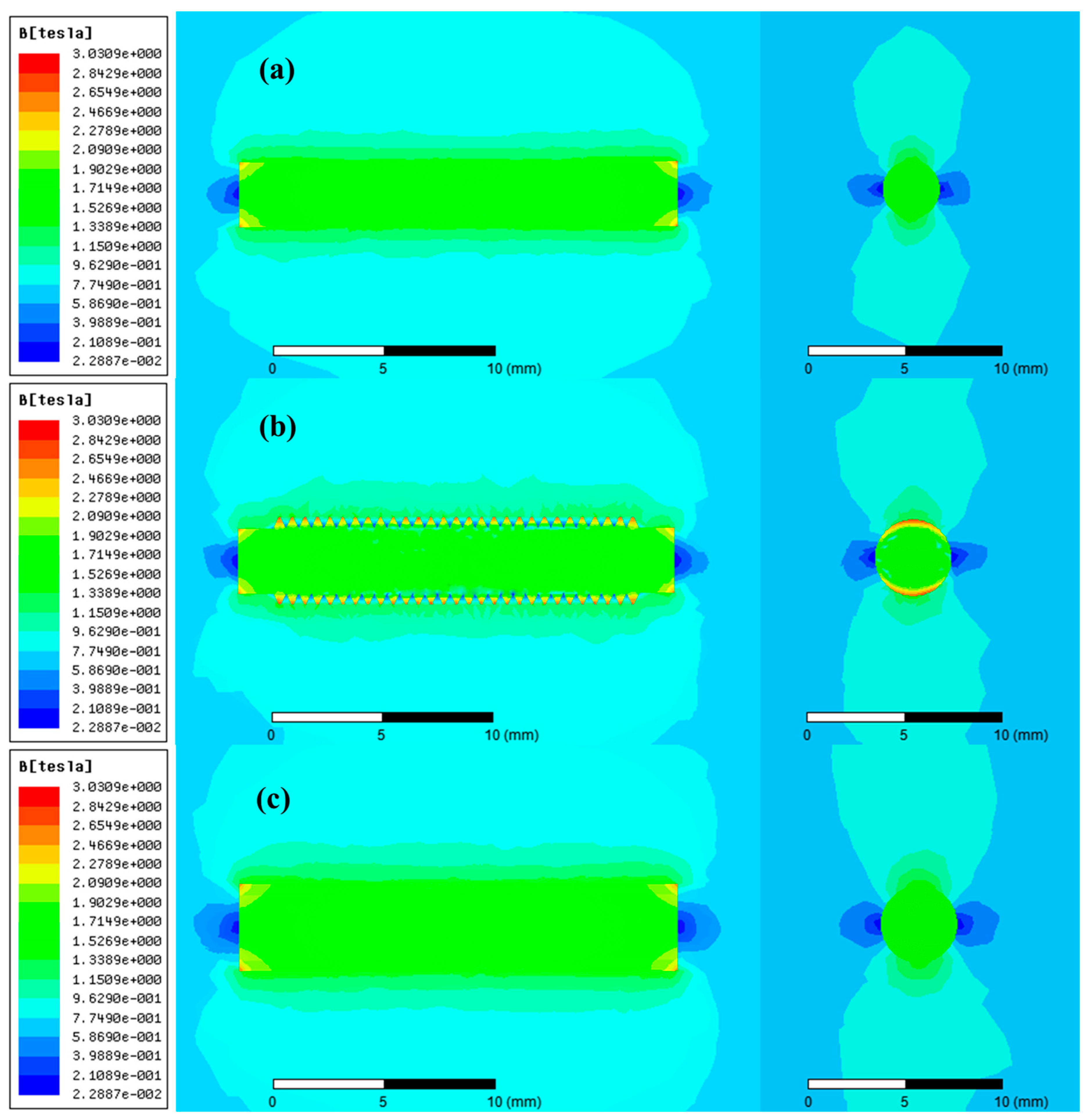
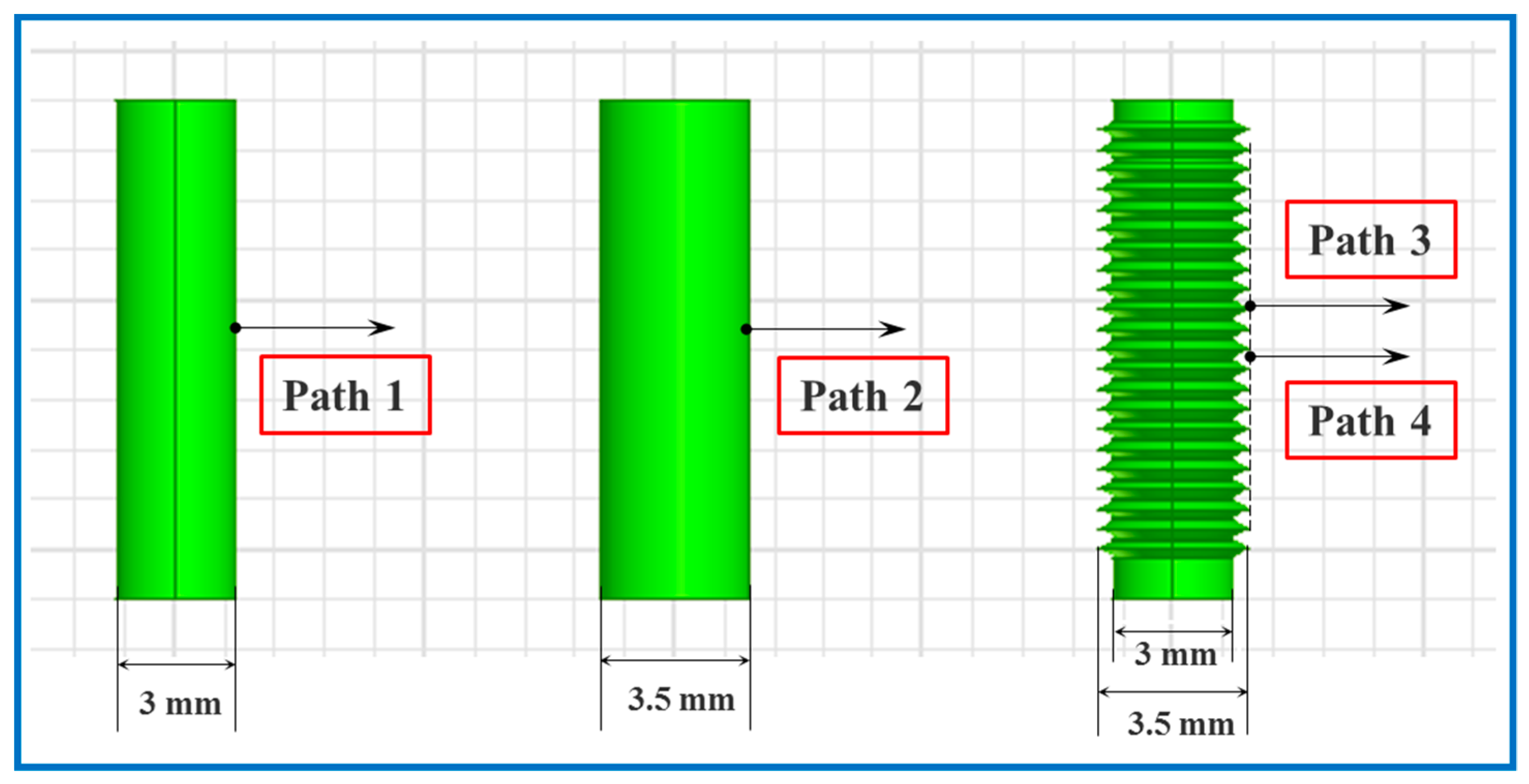
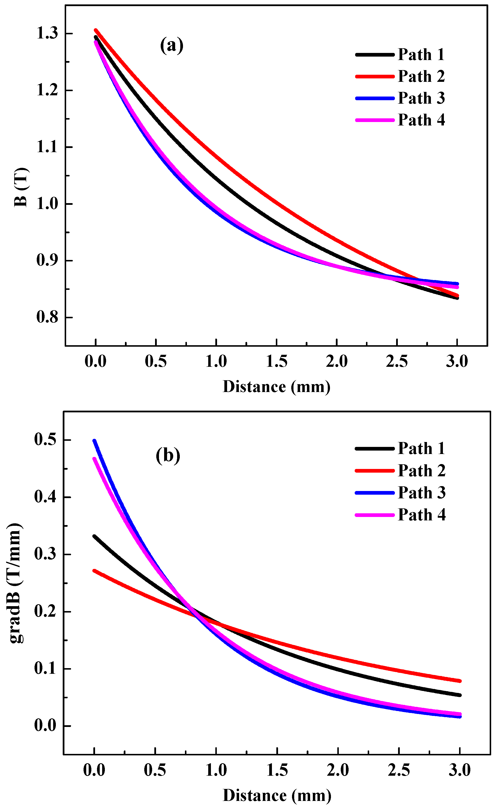
Considering the structural similarity and variability of the screw thread rod matrix and the smooth rod matrix, the simulation results were further processed along the axial and radial directions of the geometry structure to obtain the analysis results. The results in Figure 7 show that the change of the matrix unit structure has a great influence on the magnetic field distribution on the matrix surface, which then affects the recovery effect of the fine-grained iron minerals. Due to the near-equal matrix overall size, the distribution of different color clouds has a similar range of action. However, the convexity of the matrix surface arrangement causes a sharp increase of the magnetic flux density at the sharp corners. As a result, the difference between the magnetic flux density inside the iron-based material and the periphery of the matrix is widened, which in turn strengthens the magnetic field gradient at the matrix rod surface. To view the data of magnetic parameters, the specified paths are set in Figure 8. This regularity is known from the data of magnetic flux density and magnetic field gradient along the specified path in Figure 9. It can be observed that both the magnetic field induction and the magnetic field gradient along path 1, path 2, path 3, and path 4 tend to decrease as it moves away from the rod. However, the decline rates are different for the four curves in Figure 9a,b. The product of the magnetic field strength and the magnetic field gradient (B·gradB) is the key factor of the magnetic attraction on the mineral particle [8]. Figure 9c shows the variation of the product (B·gradB) with increasing distance away from the matrix rod surface. The curves of the magnetic field gradient (gradB) and that of the product (B·gradB) are similar, which indicates that the effect of the magnetic field gradient is much larger than that of the magnetic field strength. In addition, within a distance of 0.8 mm from the matrix rod, the product of the magnetic field strength and the magnetic field gradient, both along path 1 and path 2, is greater than the corresponding value of the smooth rod matrix. Thus, it follows the fact that magnetic force exerted by the screw thread rod matrix on the surrounding magnetic particles is more prominent.
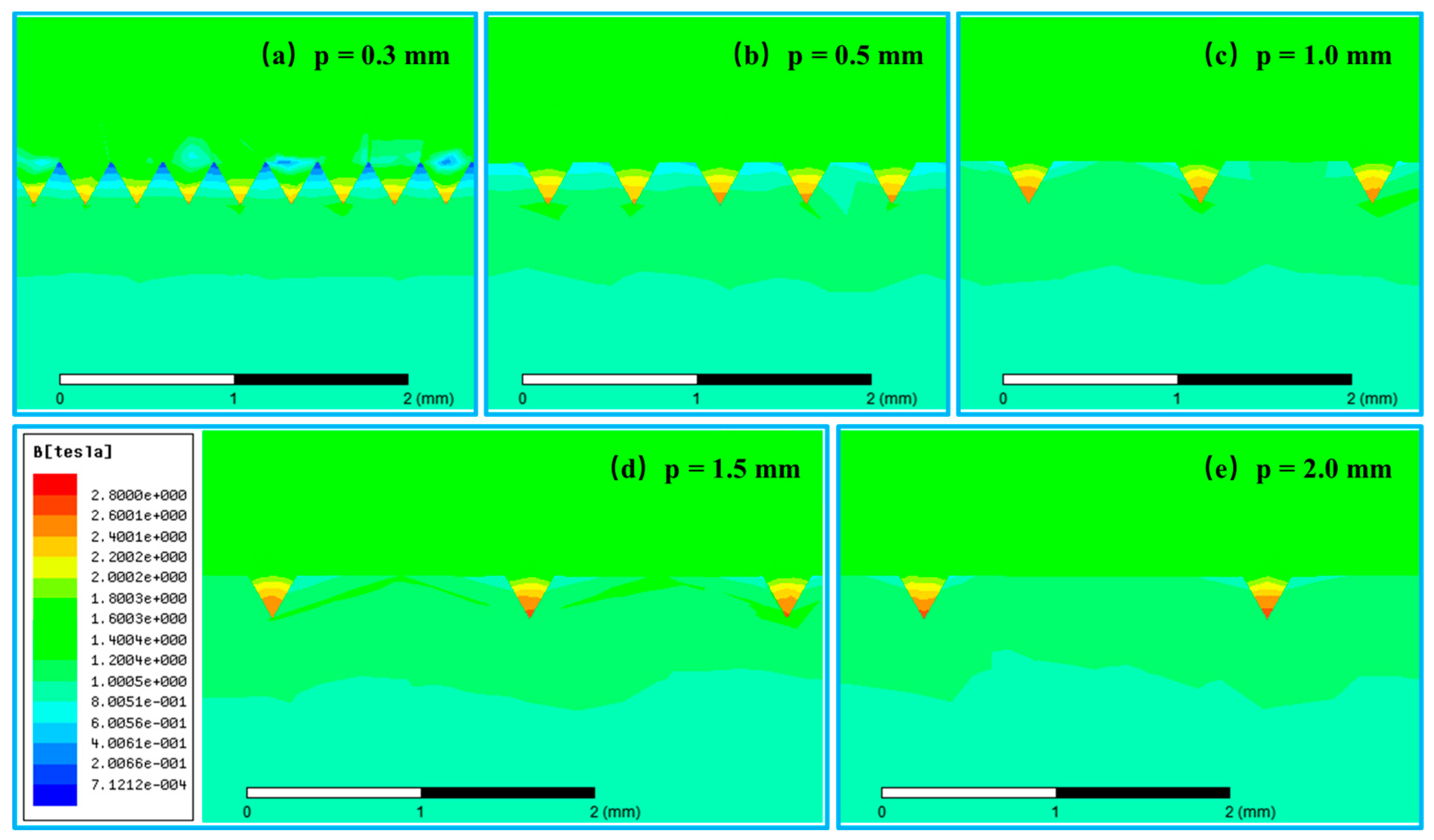
The role of screw threads on the surface of the matrix rod has been described in previous sorting tests and magnetic field analysis. However, the effect of distance between ERB on the magnetic induction distribution of the surface of screw thread rod plays an important role in explaining the beneficiation results. As can be seen from Figure 10, when the distance between ERB increases, the red area of cloud picture at the sharp corners expands. At the same time, the blue area of the groove on the rod-surface is gradually replaced by the green area. This indicates that the magnetic induction intensity in the groove becomes larger and the magnetic induction interaction with adjacent bumps diminishes. Under the action of the radial curvature of the matrix rod, both sides of the rod along the direction of the magnetic field become the aggregation area of the magnetic force lines. In addition, the screw threads on the matrix rod surface make the periodic change of the magnetic induction intensity in the axial direction of the rod. This leads to the magnetic field inhomogeneity along the axial direction, i.e., the axial magnetic field gradient. When the distance between ERB is equal to zero or is infinite, the screw thread rod is equivalent to the smooth bar. Therefore, the pitch of the screw thread rod matrix is either too large or too small, which is not conducive to strengthening the capturing effect of magnetic minerals. This also reasonably explains why magnetic separation is best when the pitch is 0.5 mm for fine hematite ore tailings from the Dong Anshan beneficiation plant.
5. Conclusions
Based on the work in this paper, it is confirmed that the structural change of the matrix has an important influence on the magnetic field distribution and on the capture of weakly magnetic mineral particles. The screw thread rod matrix has the dual advantages of the smooth rod matrix and the grooved magnetic plate, i.e., the advantage of better slurry fluidity through the matrix and higher magnetic field gradient at the sharp corners. Compared with the smooth rod matrix, the screw thread rod matrix enhances the inhomogeneity of the axial magnetic induction intensity on the surface of the matrix. Furthermore, the combined effects of the radial curvature of the rod and the inhomogeneous magnetic field in the axial direction improve the recovery of fine-grained iron minerals. For the fine hematite ore tailings from the Dong Anshan beneficiation plant, the suitable distance between ERB on the surface of 3 mm rod matrix is 0.5 mm, offering a recovery increase of 3% over the smooth rod matrix. Besides, whether it is for the screw thread rods or for the smooth matrix rods, the smaller column gap provides a better recovery in the case of no clogging of matrices. Numerical test results of magnetic field distribution based on matrix parameters show that the product of the magnetic field strength and the magnetic field gradient for the screw thread rod matrix is greater than the corresponding value of the smooth rod matrix within 1 mm along the radial direction on the matrix rod. Therefore, the magnetic force exerted by the screw thread rod matrix on the surrounding magnetic particles is more prominent. The influences of structural parameters of magnetic matrix on the iron minerals processing are worthy of attention in the field of high gradient magnetic separation. By adjusting the structural parameters of the matrix, not only the recovery rate of the weak magnetic minerals can be improved, but also the background magnetic field strength can be reduced under the same sorting effect so as to improve the power consumption of the equipment.
Acknowledgments
This creative research work was supported by the National Natural Science Foundation of China (Grant No. 51604064), the Fundamental Research Funds for the Central Universities (Grant No. 150103003) and the Doctoral Scientific Research Foundation of Liaoning Province (201601027), for which the authors express their appreciation.
Author Contributions
W.L., Y.H., and E.P. conceived and designed the experiments; W.L. performed the physical experiments; W.L. and R.X. performed the numerical experiments; W.L. and Y.H. analyzed the data; E.P. contributed materials/analysis tools; W.L. wrote the paper.
Conflicts of Interest
The authors declare no conflict of interest.
References
- Wills, B.A.; Napier-Munn, T.J. Mineral Processing Technology, 7th ed.; Elsevier Science & Technology Books: Amsterdam, The Netherlands, 2006. [Google Scholar]
- Svoboda, J.; Fujita, T. Recent developments in magnetic methods of material separation. Miner. Eng. 2003, 16, 785–792. [Google Scholar] [CrossRef]
- Chen, L.Z.; Xiong, D.H.; Huang, H.C. Pulsating high-gradient magnetic separation of fine hematite from tailings. Miner. Metall. Process. 2009, 26, 163–168. [Google Scholar]
- Newns, A.; Pascoe, R.D. Influence of path length and slurry velocity on the removal of iron from kaolin using a high gradient separator. Miner. Eng. 2002, 15, 465–467. [Google Scholar] [CrossRef]
- Karapinar, N. Magnetic separation of ferrihydrite from wastewater by magnetic seeding and high-gradient magnetic separation. Int. J. Miner. Process. 2003, 71, 45–54. [Google Scholar] [CrossRef]
- Svoboda, J. A realistic description of the process of high-gradient magnetic separation. Miner. Eng. 2001, 14, 1493–1501. [Google Scholar] [CrossRef]
- Watson, J.H.P. Theory of capture of particles in magnetic high-intensity filters. IEEE Trans. Magn. 1975, 11, 1597–1599. [Google Scholar] [CrossRef]
- Baik, S.K.; Ha, D.W.; Ko, R.K.; Kwon, J.M. Magnetic field and gradient analysis around matrix for HGMS. Phys. C Supercond. 2010, 470, 1831–1836. [Google Scholar] [CrossRef]
- Song, S.; Lopez-Valdivieso, A.; Ding, Y. Effects of nonpolar oil on hydrophobic flocculation of hematite and rhodochrosite fines. Powder Technol. 1999, 101, 73–81. [Google Scholar] [CrossRef]
- Wasmuth, H.D.; Unkelbath, K.H. Recent developments in magnetic separation of feebly magnetic minerals. Miner. Eng. 1991, 4, 825–837. [Google Scholar] [CrossRef]
- Sivamoha, R. The problem of recovering very fine particles in mineral processing—A review. Int. J. Miner. Process. 1990, 28, 247–288. [Google Scholar] [CrossRef]
- Tsouris, C. Particle flocculation and filtration by high-gradient magnetic fields. Sep. Sci. Technol. 1997, 32, 599–616. [Google Scholar] [CrossRef]
- Luo, L.; Nguyen, A.V. A review of principles and applications of magnetic flocculation to separate ultrafine magnetic particles. Sep. Purif. Technol. 2017, 172, 85–99. [Google Scholar] [CrossRef]
- Song, S.; Lu, S.; Lopez-Valdivieso, A. Magnetic flocculation of hematite and limonite fines as hydrophobic flocs from iron ores. Miner. Eng. 2002, 15, 415–422. [Google Scholar] [CrossRef]
- Tsouris, C.; Scott, T. Flocculation of paramagnetic particles in a magnetic field. J. Colloid Interface Sci. 1995, 171, 319–330. [Google Scholar] [CrossRef]
- Luo, L.; Zhang, J.; Yu, Y. Recovering limonite from Australia iron ores by flocculation-high intensity magnetic separation. J. Cent. South Univ. Technol. 2005, 12, 682–687. [Google Scholar] [CrossRef]
- Škvarla, J.; Zelenak, F. Magnetic-hydrophobic coagulation of paramagnetic minerals: A correlation of theory with experiments. Int. J. Miner. Process. 2003, 68, 17–36. [Google Scholar] [CrossRef]
- Chen, L. Effect of magnetic field orientation on high gradient magnetic separation performance. Miner. Eng. 2011, 24, 88–90. [Google Scholar] [CrossRef]
- Zeng, W.; Dahe, X. The latest application of SLon vertical ring and pulsating high-gradient magnetic separator. Miner. Eng. 2003, 16, 563–565. [Google Scholar] [CrossRef]
- Stadtmuller, A.A.; Good, J.A.; Riches, N.J. Developments in superconducting magnetic separation. Ind. Miner. 1988, 3, 58–69. [Google Scholar]
- Padmanabhan, N.P.H.; Sreenivas, T. Process parametric study for the recovery of very-fine size uranium values on super-conducting high gradient magnetic separator. Adv. Powder Technol. 2011, 22, 131–137. [Google Scholar] [CrossRef]
- Kim, Y.G.; Song, J.B.; Yang, D.G.; Lee, J.S.; Park, Y.J.; Kang, D.H. Effects of filter shapes on the capture efficiency of a superconducting high-gradient magnetic separation system. Supercond. Sci. Technol. 2013, 26, 1–7. [Google Scholar] [CrossRef]
- Zhang, K.; Nieto, A.; Kleit, A.N. The real option value of mining operations using mean-reverting commodity prices. Miner. Econ. 2015, 28, 11–22. [Google Scholar] [CrossRef]
- Zhang, K.; Kleit, A.; Nieto, A. An economics strategy for criticality—Application to rare earth element Yttrium in new lighting technology and its sustainable availability. Renew. Sustain. Energy Rev. 2017, 77, 899–915. [Google Scholar] [CrossRef]
- Zhang, K.; Kleit, A.N. Mining rate optimization considering the stockpiling: A theoretical economics and real option model. Resour. Policy 2016, 47, 87–94. [Google Scholar] [CrossRef]
- Eisenstein, I. Magnetic traction force in a HGMS with an ordered array of wires: I. IEEE Trans. Magn. 1978, 14, 1148–1154. [Google Scholar] [CrossRef]
- Chen, L.; Qian, Z.; Wen, S.; Huang, S. High-gradient magnetic separation of ultrafine particles with rod matrix. Miner. Process. Extr. Metall. Rev. 2013, 34, 340–347. [Google Scholar] [CrossRef]
- Too, C.O.; Parker, M.R.; Gerber, R.; Fletcher, D. Optimisation of matrix design in high gradient magnetic separation. J. Phys. D Appl. Phys. 1986, 19, L1–L4. [Google Scholar] [CrossRef]
- Zheng, X.; Wang, Y.; Lu, D. Study on capture radius and efficiency of fine weakly magnetic minerals in high gradient magnetic field. Miner. Eng. 2015, 74, 79–85. [Google Scholar] [CrossRef]
- Chen, L.; Ding, L.; Zhang, H.; Huang, J. Slice matrix analysis for combinatorial optimization of rod matrix in PHGMS. Miner. Eng. 2014, 58, 104–107. [Google Scholar] [CrossRef]
- Zheng, X.; Wang, Y.; Lu, D. Investigation of the particle capture of elliptic cross-sectional matrix for high gradient magnetic separation. Powder Technol. 2016, 297, 303–310. [Google Scholar] [CrossRef]
- Li, Z.; Watson, J.H.P. The effect of the matrix shape on vortex magnetic separation. Miner. Eng. 1995, 8, 401–407. [Google Scholar] [CrossRef]
- Zheng, X.; Wang, Y.; Lu, D.; Li, X. Theoretical and experimental study on elliptic matrices in the transversal high gradient magnetic separation. Miner. Eng. 2017, 111, 68–78. [Google Scholar] [CrossRef]
- Li, X.L.; Yao, K.L.; Liu, H.R.; Liu, Z.L. The investigation of capture behaviors of different shape magnetic sources in the high-gradient magnetic field. J. Magn. Magn. Mater. 2007, 2, 481–488. [Google Scholar] [CrossRef]
- Ku, J.G.; Chen, H.H.; He, K.; Xu, L.; Yan, Q.X. Numerical simulation of agglomeration process dynamics of ferromagnetic mineral particles in a weak magnetic field. Int. J. Miner. Process. 2014, 133, 46–51. [Google Scholar] [CrossRef]
Figure 1.
The screw thread rod matrix.

Figure 2.
The structure schematic drawing of the cyclic horizontal magnetic field orientation high-gradient magnetic separation (HGMS) separator.
Figure 2.
The structure schematic drawing of the cyclic horizontal magnetic field orientation high-gradient magnetic separation (HGMS) separator.

Figure 3.
Influence of distance between equidistant ring-shaped bulges (ERB) (p value) on the separation performance. The matrix diameter is 3 mm, background magnetic induction is 0.8 T, the fluid velocity is 0.05 m/s, the length of stroke is 11.4 mm, and the frequency of pulsation is 30 Hz. (a) Column gap d = 2 mm; (b) Column gap d = 3 mm; (c) Column gap d = 4 mm; (d) Column gap d = 5 mm.


Figure 4.
Influence of column gap between adjacent rod elements on the separation performance. The matrix radius is 3 mm, background magnetic induction is 0.8 T, the fluid velocity is 0.05 m/s, the length of stroke is 11.4 mm, and the frequency of pulsation is 30 Hz. (a) Distance between ERB p = 0 mm. (b) Distance between ERB p = 0.5 mm. (c) Distance between ERB p = 1.0 mm. (d) Distance between ERB p = 1.5 mm. (e) Distance between ERB p = 2.0 mm.


Figure 5.
Schematic of the thread matrix rod.
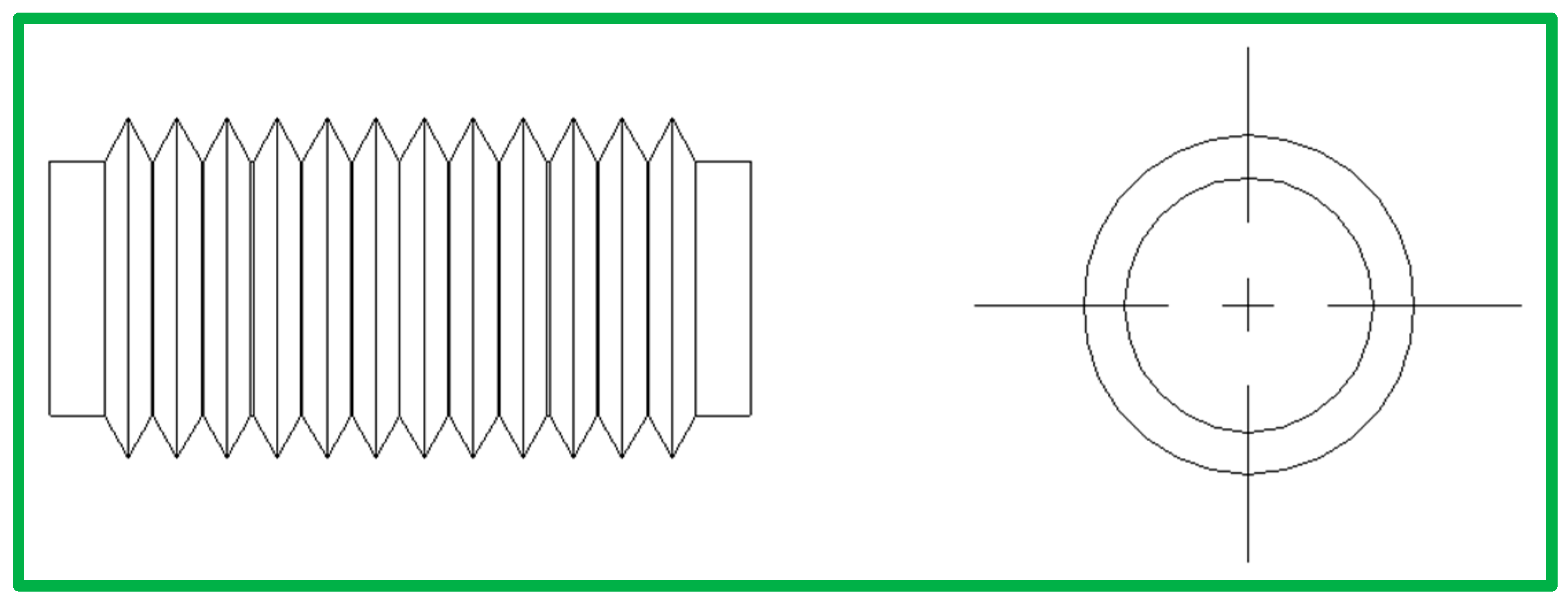
Figure 6.
Simulation model of the magnetic system.

Figure 7.
The cloud chart of magnetic induction intensity distribution in the axial and radial directions. (a) The smooth rod matrix with a diameter of 3 mm. (b) The screw thread rod matrix. (c) The smooth rod matrix with a diameter of 3.5 mm.
Figure 7.
The cloud chart of magnetic induction intensity distribution in the axial and radial directions. (a) The smooth rod matrix with a diameter of 3 mm. (b) The screw thread rod matrix. (c) The smooth rod matrix with a diameter of 3.5 mm.

Figure 8.
Path locations of different matrix rods.

Figure 9.
The data of magnetic parameters along the specified path. (a) The relationship between the magnetic field strength and the distance moving away from the matrix surface. (b) The relationship between the magnetic field gradient and the distance moving away from the matrix surface. (c) The relationship between the product of the magnetic field strength and the magnetic field gradient and the distance moving away from the matrix surface.

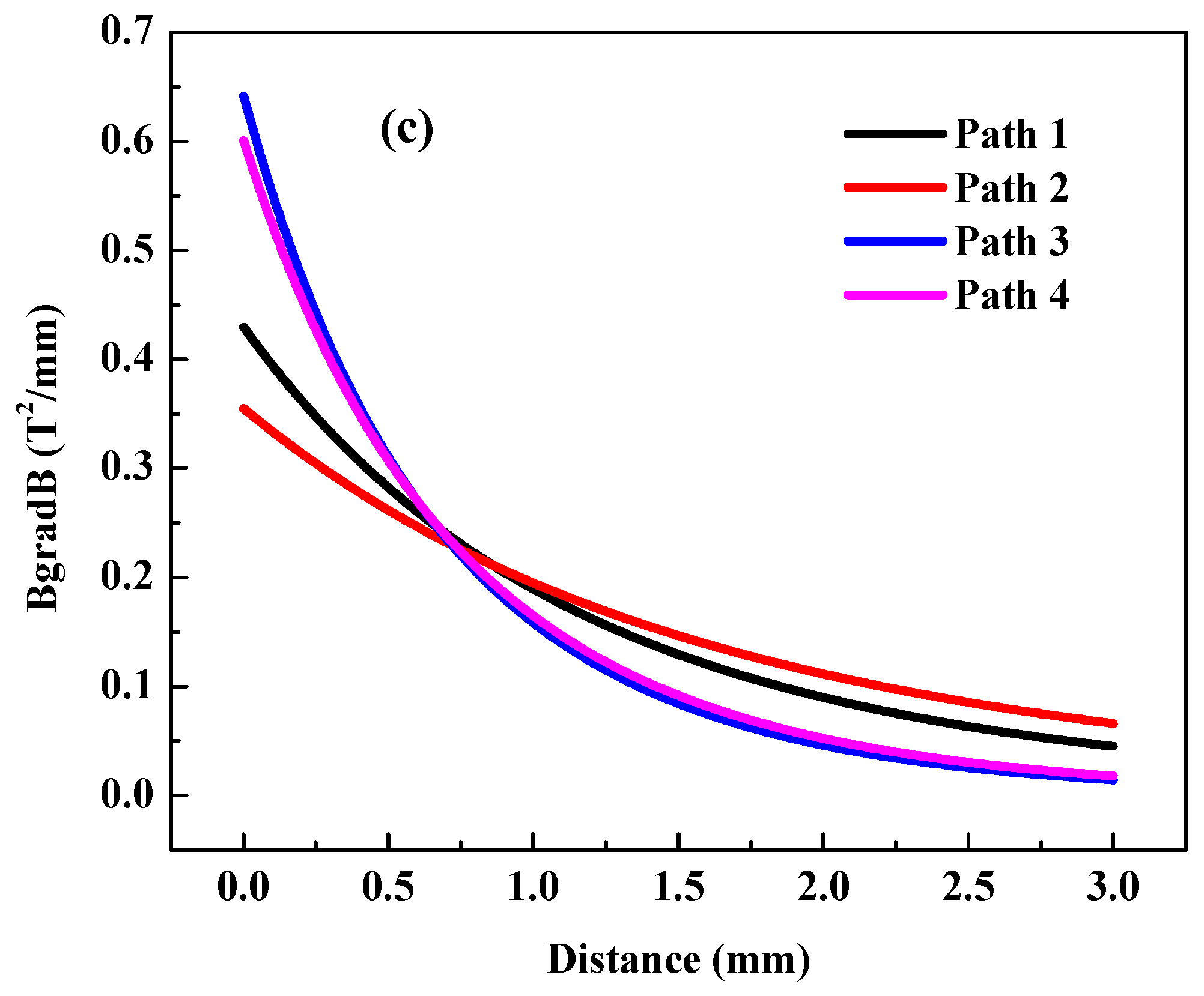
Figure 10.
The cloud chart of magnetic induction intensity distribution based on different distances between ERB. (a) Distance between ERB p = 0.3 mm. (b) Distance between ERB p = 0.5 mm. (c) Distance between ERB p = 1.0 mm. (d) Distance between ERB p = 1.5 mm. (e) Distance between ERB p = 2.0 mm.
Figure 10.
The cloud chart of magnetic induction intensity distribution based on different distances between ERB. (a) Distance between ERB p = 0.3 mm. (b) Distance between ERB p = 0.5 mm. (c) Distance between ERB p = 1.0 mm. (d) Distance between ERB p = 1.5 mm. (e) Distance between ERB p = 2.0 mm.


Table 1.
Experimental conditions.
| Type of Parameters | Numerical Values |
|---|---|
| Magnetic field intensity (T) | 0.8 |
| Feed solid density (%) | 20 |
| Flowing speed of slurry (cm/s) | 4.39 |
| Output size (mm) | 10 |
| Pulsating stroke (mm) | 11.4 |
| Pulsating frequency (Hz) | 30 |
| Distance between ERB (mm) | p = 0, 0.5, 1.0, 1.5, 2.0 |
| Column gap in matrix (mm) | d = 2, 3, 4, 5 |
Table 2.
Material of the physical model.
| Type of Parameters | Description |
|---|---|
| Material of ferrite yoke | Low carbon steel (Q235) |
| Material of exiting coils | Copper |
| Material of magnetic pole | Low carbon steel (Q235) |
| Material of matrix | Stainless steel (SUS430) |
| Separating zone | Vacuum |
| Gap between magnetic poles (mm) | 80 |
| Number of turns in the excitation coil | 300 |
| Magnetizing current (A) | 87 |
| Background magnetic induction (Tesla) | 0.8 |
© 2018 by the authors. Licensee MDPI, Basel, Switzerland. This article is an open access article distributed under the terms and conditions of the Creative Commons Attribution (CC BY) license (http://creativecommons.org/licenses/by/4.0/).
Share and Cite
MDPI and ACS Style
Li, W.; Han, Y.; Xu, R.; Gong, E. A Preliminary Investigation into Separating Performance and Magnetic Field Characteristic Analysis Based on a Novel Matrix. Minerals 2018, 8, 94. https://doi.org/10.3390/min8030094
AMA Style
Li W, Han Y, Xu R, Gong E. A Preliminary Investigation into Separating Performance and Magnetic Field Characteristic Analysis Based on a Novel Matrix. Minerals. 2018; 8(3):94. https://doi.org/10.3390/min8030094
Chicago/Turabian StyleLi, Wenbo, Yuexin Han, Ruiqing Xu, and Enpu Gong. 2018. "A Preliminary Investigation into Separating Performance and Magnetic Field Characteristic Analysis Based on a Novel Matrix" Minerals 8, no. 3: 94. https://doi.org/10.3390/min8030094
Note that from the first issue of 2016, this journal uses article numbers instead of page numbers. See further details here.