1. Introduction
The OpenOrbiter mission seeks to implement the designs created by the Open Prototype for Educational NanoSats (OPEN) program. OPEN is producing a set of design documents, construction instructions and a testing plan to facilitate the creation of low-cost CubeSat-class satellites. Reducing the cost of spacecraft development in this form factor allows spacecraft development efforts to be funded from teaching funds, instead of requiring faculty to seek research funds to conduct this activity. Using teaching funds (instead of research funds) facilitates greater student leadership and involvement, as it reduces the risk of mission failure to the responsible faculty member. Additionally, as teaching funds are generally recurring, this approach facilitates incorporation of the small satellite program in curriculum on a year-upon-year basis.
The OPEN design, which is implemented by OpenOrbiter, also incorporates technical advancements. It places the subsystem circuit boards on the four sides of the spacecraft and allows payload/mission-specific component placement in a 5 cm × 5 cm × 10 cm area in the middle of the spacecraft (facilitating the placement of a propellant tank at the spacecraft’s center of mass and effective use of the overhang space included in the CubeSat specification).
This paper describes, principally, the OpenOrbiter spacecraft. It briefly presents the solution space provided by the OPEN framework and details the specific choices made for OpenOrbiter. The objectives for the program (both from a university perspective and an OPEN implementation perspective) are discussed. The requirements and constraints that flow from these objectives are presented and the ensuring mission concept of operations, architecture and high-level design are presented.
2. Background
The OpenOrbiter initiative draws from a wealth of prior work in two disciplines, small satellite engineering and education. OpenOrbiter, as a student-led, student-centric effort operating within the context of a university environment, must achieve science, engineering and educational objectives. The foundation for that attainment is now reviewed.
2.1. Small Satellite Engineering
Some would argue that small spacecraft have their foundations in the earliest launches. Sputnik is pointed to, by some, as an example of a small satellite. Dickson, for example, describes it as being the “size of a beach ball” and weighing “a mere 184 pounds” [
1]. Thinking of something this size as small is not unsurprising, considering the size of many current and historical spacecraft. Intelsat 10, a communications satellite launched in 2004, had an initial launch mass of 5,600 kg [
2].
In 2000, Bob Twiggs (then at Stanford leading the Satellite Quick Research Testbed project) changed the notion of the size of a small satellite [
3]. The Orbiting Picosatellite Automatic Launcher (OPAL) deployed six “hockey puck-sized” spacecraft, weighing 1 kg [
3]. Following this success, Twiggs and Jordi Puig-Suari developed specifications for the CubeSat form factor and developed the commonly used launcher, the Poly-PicoSatellite Orbital Deployed (P-POD). The first CubeSat was launched in 2003. To-date, more than 60 CubeSats have successfully reached orbit [
4]; numerous others have been developed and lost to launch failures or never launched [
5]. Twiggs is now working on making small satellites even smaller via working on a satellite one-eighth the volume of a CubeSat (5 cm × 5 cm × 5 cm) called the PocketQub [
3]. This spacecraft is targeted at enhancing high school STEM education.
Thakker and Swenson [
6] proffer that “most university satellite programs have focused more on their educational missions” than on advancing science and science and engineering techniques. Several examples of science missions exist, however, including the University of Illinois ION-1 (oxygen airglow photometer) and ION-2 (neutral hydrogen photometer) spacecraft and Taylor University’s TEST (Langmuir plasma probe, electric field boom, VLF receiver, SSD spectrometer and transient photometer) and TU SAT-1 (Langmuir plasma probe, tether and Nitol tether). Swartwout [
7] proffered, in 2004, that “university-class satellites” can be “disruptive” research platforms: they can alter the way that space research is carried out (though the veracity of these claims have been reduced somewhat in later work). It is asserted that this disruptive capability comes from the particular strengths of research universities: students’ enthusiasm and novel ideas and the “freedom to fail” [
7].
In 2012, Swartwout [
8] noted that university programs have moved away from being “beepsats”, a term used to characterize spacecraft lacking “a compelling science, technology or communications payload” to incorporating real scientific, engineering or other goals. These missions, he noted (in 1997), should have risk from their unique characteristics and not be an exercise in navigating complexity [
9]. A university program, under these circumstances, can be beneficial to students’ educational attainment and investigate “risky and/or innovative methods” [
9].
University missions can and do employ the same mission analysis and design techniques [
10,
11,
12] utilized by industry, military and government. Chin,
et al. [
13] proffer that the standardization in the CubeSat development community is critical to the form factor’s success; this of course is atypical for space missions which (while reusing proven/qualified components) generally implement mission or program-specific designs.
CubeSats are also pushing technical boundaries. Twiggs and Malphrus [
14] provide an overview. CubeSats are using (and in some cases being used to test) advances such as: plastic printed structures, deployable solar panels and technologies (such as Stanford’s Hemispherical Anti-Twist Tracking System, HATTS [
15]), advanced propulsion (e.g., heated Freon gas) and 3D printed propulsion.
Swartwout [
16], however, highlights two key problems: spacecraft projects are not responsive to university needs of creating a sustained educational program or attracting external research sponsorship. Prior to the advent of CubeSats, Swartwout proffers that schools “rarely, if ever” complete a second project after an initial success. CubeSats, he asserts, are changing this; however, it is unclear as to whether this has changed significantly, except for at a few key schools.
2.2. Educational Foundation
Small satellites can easily integrate into a project-based learning (PBL) methodology. The PBL technique seeks to create student learning through immersion in a project. Students are tasked with overcoming foreseen and unforeseen challenges and learn during the process.
Zhou [
17] identifies the critical nature of creativity to engineers. This creativity can be developed via a variety of techniques including creating a conducive environment and implementing problem-solving. Zhou identifies PBL as a technique that can help create engineering creativity through student-centered, self-directed collaborative exercises. An eight-step approach is proposed beginning with (1) “problem setting”, incorporating (2) brainstorming, (3) systematization, (4) thematic selection, (5) formulation of learning tasks, (6) knowledge acquisition via self-studying, (7) knowledge integration, and concluding with (8) structuring the knowledge in terms of the problem-at-hand.
Smith,
et al. [
18] present work at the Massachusetts Institute of Technology (MIT) related to incorporating CubeSat development in undergraduate aerospace engineering and planetary science curriculum. Crawley,
et al. [
19] pioneered an approach entitled “Conceive-Design-Implement-Operate” (CDIO) at MIT, based upon feedback from numerous engineering education stakeholders (educators, industry, students,
etc.). Smith,
et al. [
18] expand this by asserting that there is a significant need, in aerospace engineering, for shared understanding between scientists and engineers. In the ExoplanetSat initiative, students from the Department of Earth, Atmospheric and Planetary Sciences were involved in the design process, via enrolment in the three-semester CDIO course progression. Smith,
et al. note that this required students to engage in a science versus engineering trade process throughout the mission, analogous to how a pristine-class mission of this type would be performed. While this expanded the scope of interdisciplinary collaboration slightly, it does not fully encompass all discipline-types that would be required to be involved in a mission of this type.
Rodriguez-Osorio and Ramirez [
20] present work at the ETSI de Telecomunicación in Madrid, Spain related to an extracurricular NanoSat project. This twenty-one month project was student-conceived and implemented, under faculty supervision. An antenna array designed for the purpose of inter-spacecraft communication (for a CubeSat-size craft) was created and its performance characterized. As donations were received for most components required, the project was performed on a limited budget. Rodriguez-Osorio and Ramirez proffer that this experiment demonstrates the feasibility of implementing simulated industry-analog engineering projects with limited resources and “promising results” [
20]. The work, while conceptually promising, deals only with a limited subsystem and relies on donations that may not be available to other institutions or projects.
Student involved projects (whether attempting to achieve exclusively learning goals or a combination of substantive research and education) carry with significant risk of project failure or less-than-complete success [
21]. This risk comes from conventional risk sources (e.g., delays beyond project manager control, supplier issues); many elements of conventional risk are also exacerbated by the project conditions typical of student projects (e.g., participant lack of knowledge and inexperience). Student-involved projects also incorporate their own particular risk factors driven by the academic environment (e.g., a prioritization of course work over project performance, students joining and leaving the project at semester breaks and other times). Risk and general management, thus, is crucially important.
3. Objectives
The OpenOrbiter initiative is one of several complementary small satellite development efforts underway at the University of North Dakota (UND). As such, the mission’s goals combine the technology demonstration needs and development requirements of the OPEN framework, a project targeted to provide benefits on a national and international level, with university and state-level development goals. The program and mission objectives are presented in
Section 3.1;
Section 3.2 discusses the educational objectives specific to the implementation of the OpenOrbiter program at UND.
3.1. Program and Mission Objectives
3.1.1. University of North Dakota Small Satellite Objectives
Several small spacecraft design and development projects are ongoing at the University of North Dakota. These projects share several common goals and objectives which are presented below.
Primary:
Secondary:
To advance the capability of the University of North Dakota and other North Dakota-based institutions with regards to small spacecraft development to continuously prepare for ever greater future opportunities.
To assure that a level of risk commensurate with the importance of success is undertaken throughout program missions.
To demonstrate management, scientific and ethical standards and practices that will pave the way for a successful long-term program.
3.1.2. Open Orbiter Mission Objectives
The OpenOrbiter mission seeks to achieve goals relevant to the research objectives of the University of North Dakota and the John D. Odegard School of Aerospace Sciences. These include technical objectives as well as developing technologies that would be relevant to local and regional development. As the demonstration mission for a project with an international scope, OpenOrbiter also seeks to advance the objectives of the OPEN program, through demonstrating the OPEN designs and facilitating the creation and refinement of development and testing plans.
Primary:
Secondary:
To develop a remote sensing payload for the visible portion of the electromagnetic spectrum suitable for Earth science, planetary science, intelligence, space situational awareness, and other applications
To demonstrate and test an innovative structural design, layout and electrical configuration for the CubeSat form factor.
To demonstrate the capabilities of North Dakota educational institutions and program team members to design, develop and operate a small satellite in preparation for larger missions
To provide educational opportunities related to spacecraft design, aerospace project management, engineering and computational sciences for students and others associated with the project.
3.2. Educational Facilitation Objectives
The educational objectives of the OpenOrbiter project are multi-faceted. They include providing benefits to student participants at the University of North Dakota and creating national and worldwide benefits by ensuring the completion of the OPEN documentation and its validation via hardware flight testing.
3.2.1. Creation of Benefits to Participants
The OpenOrbiter program is designed to provide several classes of benefits to its participants. These include: (1) gaining experience in developing a spacecraft, (2) gaining experience working in an industry-analog aerospace engineering environment, (3) learning specific technical skills, (4) demonstrating competence in technical skills and (5) obtaining the professional development benefits from participating in a project with a highly emotive and demonstrable product.
Spacecraft development projects are normally high-value projects that do not facilitate the substantive involvement of students or junior (entry-level) employees. Because of this, an aspirant to spacecraft development may be a substantial portion of the way into his or her career before he or she is able to actually work with real spacecraft hardware. While this may decrease project risk, it removes a key source of innovation. It also prevents students from gaining the experience that is only possible via hands-on interaction with a flight-quality or prototype system. OpenOrbiter, as with most university-run small spacecraft programs allows students complete access to the flight and prototype hardware and thus the opportunity to gain this experience.
A key challenge for many students (and, by extension, the companies that eventually employ them) is learning to work with and speak the vernacular of the various disciplines that must be involved in an engineering project. Students may make it all the way through their university career (and even years into their initial employment) before they are required to communicate, about technical concepts, with those outside their particular technical ‘silo’. Many small spacecraft (and other engineering/hands-on STEM projects) provide STEM students with experience working with other STEM students (in some cases, more aptly, providing technology and engineering students with the opportunity to work with other technology and engineering students). OpenOrbiter takes this one step further by incorporating students from business, public administration, fine arts, education and other disciplines, in discipline-appropriate roles (e.g., project management, website design, outreach).
Many small spacecraft projects highlight technical skill learning as a key educational outcome. Skills such as systems engineering require use in a project of reasonable size to be reinforced through use and refined. Like most small spacecraft programs, OpenOrbiter provides participants with this opportunity.
Students, seeking employment at the end of their college careers, desire involvement with demonstrable projects that can be highlighted to potential employers as a demonstration of their skills and abilities (and particular competency as compared to ‘book-learning-only’ students). Small spacecraft projects provide this demonstrable experience and are an emotive project for presentation to employers. OpenOrbiter participants can also highlight their ‘cross-silo’ communications and working environment as a key benefit to prospective employers.
Finally, students desire to develop and document their professional skills. Milestones such as design reviews and integrator and launch provider acceptance allow students to document their participation in terms of external standards (to differentiate participation from joining an extra-curricular club, for example). Giving participants titles which reflect, appropriately, their project responsibility and authority also helps ensure this benefit accrues.
3.2.2. Creation of National and Worldwide Benefits
Due to its goal to test and demonstrate the OPEN framework, OpenOrbiter has objectives which seek to drive national and worldwide benefits. The benefits of OPEN include: (1) lowering the cost of entry, for educational institutions, to operating a small spacecraft program, (2) lowering research program cost via allowing project-specific modifications to subsystems without requiring vendor negotiation or redesign from scratch, (3) facilitating student involvement in real research, instead of education-centric integration-only projects, and (4) facilitating initial mission-efforts becoming a program by allowing initial mission performance to directly translate to program performance (and not requiring a substantial design cost outlay between integrating a vendor-provided kit spacecraft and producing a locally-designed spacecraft affordable to teaching budgets).
OpenOrbiter provides several specific benefits to the OPEN initiative. These include: (1) space-validating the OPEN design, so as to assure potential users of its suitability for use, (2) providing the details and implementation experience required to refine and add best practices to the implementation and testing plans, and (3) validating the suitability and completeness of the design, implementation and testing documentation.
4. Requirements and Constraints
The objectives of the OpenOrbiter mission have been utilized, as per the typical mission design and analysis approach (e.g., presented in [
10,
11,
12]) to create derivative requirements and constraints. Additional constraints from the development and operation environment have also been added. These are now presented.
4.1. Requirements
Requirements:
A functional spacecraft shall be designed, developed, deployed and demonstrated.
The spacecraft shall be compliant with revision 12 of the CubeSat form factor and launch provider integration standards (with the later taking precedence over the former in case of any conflict).
The spacecraft shall be capable of producing imagery with a minimum spatial resolution of 150 meters
Software shall be developed which can produce a 3x increase in spatial resolution over the optical resolution.
The spacecraft shall be capable of executing critical elements of constellation operations including position determination and attitude correction
The mission shall incorporate students in the design, development and operation of the spacecraft.
The spacecraft shall have sufficient pointing knowledge to determine whether a desired target has been imaged.
Relevant documentation to allow future fabrication of all in-house designed hardware elements shall be produced.
4.2. Constraints
Constraints:
The spacecraft shall be produced with a component cost that is less than or equal to the $ 5,000.
The spacecraft shall be designed, developed and readied for flight before December 31, 2013.
The spacecraft and associated development and operations procedures shall comply with all requirements and constraints imposed by the launch provider
All risks that could cause catastrophic mission failure or result in diminished capabilities to the extent that the required capabilities cannot be demonstrated shall be identified and mitigated.
5. Mission Concept of Operations
The mission concept of operations defines, at a high level, how the mission will be carried out. The mission concept of operations for the OpenOrbiter mission is now presented.
The OpenOrbiter mission is constrained, in terms of the traditional mission concept elements, by the infrastructure, funding and launch services available.
Table 1 lists the mission concept of operations elements and the possible options available.
Table 2 lists the option selected for each concept of operations element.
Table 1.
Mission Concept of Operations Solution Space.
Table 1.
Mission Concept of Operations Solution Space.
| Element | Options | Considerations |
|---|
| Data Delivery | Data collected, processed/enhanced onboard and transmitted to the ground
Data collected and transmitted to ground for processing
Partial onboard processing | Spacecraft computer performance, power considerations and data link constraints will drive the data processing/delivery decision |
| Communications Architecture | UND Ground Station
Academic or Commercial Network | UND possesses most of the hardware required to operate a small ground station. This is likely the lowest cost option and maximizes student involvement
An academic network such as GENSO or the concept proposed in [22] could be used; however, reliability, student involvement and ITAR implications must be considered |
| Tasking, Scheduling and Control | Autonomous Control Required | Given the limited communications windows that will be possible and lack of 24x7 communications capability, the spacecraft must be able to perform autonomously based on controller-specified tasking |
| Mission Timeline | The spacecraft must be available for launch at the data specified by the launch provider
The mission duration will be determined by the time that it takes the low-Earth orbit to decay (no propulsion is available to boost the orbit) | The timeline is driven by the ELANA/CLI program schedule for launch opportunities
Current guidance from NASA/CalPoly does not allow propulsion elements |
Table 2.
Mission Concept of Operations.
Table 2.
Mission Concept of Operations.
| Element | Selected Option |
|---|
| Data Delivery | Data will be collected, processed / enhanced onboard and transmitted to the ground |
| Communications Architecture | UND Ground Station |
| Tasking, Scheduling and Control | Autonomous Control Implemented |
| Mission Timeline | Defined by launch provider schedule and altitude (which will define orbital life) |
6. Mission Architecture
The mission architecture has several key elements. These include orbital parameters and the launch system, which are driven by the launch provider, subject and payload elements driven by the mission requirements and ground station and communications architecture elements driven by the budgetary and operational constraints of the mission.
Table 3 presents the mission architecture for the OpenOrbiter mission.
Table 3.
Mission Architecture.
Table 3.
Mission Architecture.
| Element | Description | Explanation |
|---|
| Subject | Earth and launch vehicle | Technologies required for space situational awareness, Earth sciences and planetary science missions like NEO assessment will be tested while in a low Earth orbit |
| Payload | Visual camera
GPS receiver | A visible light camera is required to image the Earth; a GPS receiver is required |
| Spacecraft Bus | To be developed by students at the University of North Dakota | One goal of this mission is to demonstrate the ability of the University of North Dakota to develop and test space hardware and gain the flight experience required for larger missions |
| Launch System | To be determined by NASA | |
| Orbit | 60° inclination and altitude of 300 to 400 km | The orbit needs to overfly Grand Forks, ND ideally multiple times per day (with a period between overflights to allow rectification of any problems that may have affected the first overflight) and be high enough to avoid most atmospheric drag (which would decrease mission life) |
| Ground System | University of North Dakota based student-operated ground station | The University of North Dakota maintains a student operations center for the International Space Station Agricultural Camera. A similar center will be created to manage the operations of the cubesat during the mission. |
| Communications Architecture | Direct communications from the satellite to UND-based ground station via amateur radio bands | Existing ground station hardware exists and will be utilized |
7. Assessment of Attainment of Requirements by Proposed Mission Approach
Assessment of the proposed mission includes evaluation of whether the mission requirements are effectively implemented by the proposed architecture, concept of operations and mission implementation approach. This process begins with an assessment of the implementation of the requirements by the architecture design. This is presented in
Table 4, below.
Table 4.
Implementation of Requirements by Mission Architecture.
Table 4.
Implementation of Requirements by Mission Architecture.
| Requirement | Fulfilling Architecture Element |
|---|
| Attained by: Spacecraft Bus |
| Attained by: Spacecraft Bus |
| Attained by: Payload, Orbit and Subject |
| Attained by software implementation, see
Section 8.5 |
| Attained by: Spacecraft Bus |
| Attained by mission implementation approach, see
Section 3.2.1 |
| Attained by: Spacecraft Bus and Orbit, Subject |
| Attained by mission implementation approach, see
Section 3.2.2 |
8. System Design
The system-level design for the OpenOrbiter spacecraft is now presented. This begins with projected mass, volume, power and link budgets. Subsequent to this, the onboard processing system design, the onboard software and software operations are presented. Finally, the physical and electrical design of the spacecraft is presented. This begins with an overview of the options available from the OPEN framework and those specifically selected for implementation in OpenOrbiter.
8.1. Volume Budget
A volume budget for OpenOrbiter has been created based upon the space utilization assignment depicted in
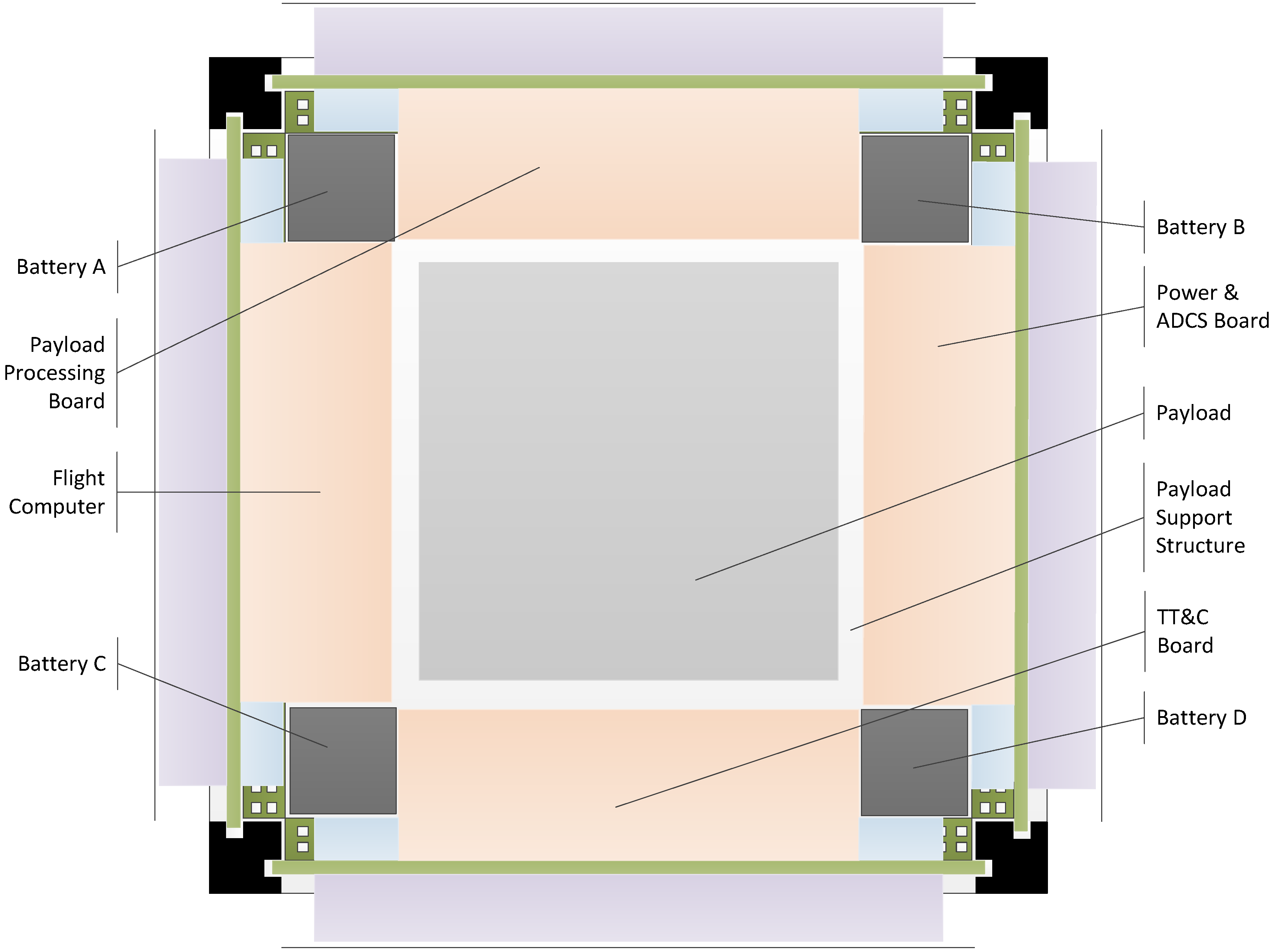
Figure 1. The OPEN framework spacecraft design includes four locations for placing boards, four locations for battery placement and a central payload area. These board slots have been utilized for a payload processing board, a flight computer board, a power and attitude determination and control board, and a telemetry, tracking and control board.
Figure 1.
OpenOrbiter Configuration.
Figure 1.
OpenOrbiter Configuration.
The volume budget, presented in
Table 5, is based on the presumption that the full space of each allocated area will be utilized for the applicable system. While this is, of course, an oversimplification, it is appropriate, as the space is not available for use by any other system. Additionally, the design makes full use of the overhang area (thus a usable cross-section space of 11.2 cm × 11.2 cm). The percentages presented in
Table 6 are based on the subsystem’s percentage of the typically utilized CubeSat form factor of 10 cm × 10 cm × 10 cm, to facilitate comparison to other missions.
Table 5.
Volume Budget.
| Subsystem | Volume Allocated |
|---|
| Payload | | |
| Payload Area | 250 | cm3 |
| Payload Board | 154.5 | cm3 |
| Onboard Processing | 154.5 | cm3 |
| ADCS | 77.3 | cm3 |
| Power | | |
| Board | 77.3 | cm3 |
| Batteries | 57.2 | cm3 |
| TT&C | 154.5 | cm3 |
Table 6.
Volume as a Percentage of Total Spacecraft Volume and comparison to SMAD 4 Values [
11].
Table 6.
Volume as a Percentage of Total Spacecraft Volume and comparison to SMAD 4 Values [11].
| Subsystem | % S/C Vol. | SMAD 4 |
|---|
| Payload | 40.45% | 41.00% |
| Onboard Processing | 15.45% | 5.00% |
| ADCS | 7.73% | 8.00% |
| Power | 13.45% | 19.00% |
| TT&C | 15.45% | 2.00% |
Table 6, in addition to presenting the volume as a percentage of the spacecraft’s volume, also compares this to values presented in
Space Mission Engineering: The New SMAD (commonly referred to as SMAD 4). As no values for volume are presented in SMAD 4, the mass values were used, based on incorporating the simplifying assumption of a consistent density between subsystems. This is, of course, not completely accurate; however, due to the need to generally keep the center of mass and center of volume in close alignment (to facilitate maneuver calculations) it is useful for comparison purposes.
8.2. Mass Budget
The mass budget for the OpenOrbiter spacecraft is presented in this section. The projected mass budget has been created based upon the simplifying assumption of a consistent density, discussed in
Section 8.1.
Table 7 presents these values, based upon the complete use of the 1.33 kg mass limit and the volume allocations presented in
Table 5. Note that, unlike in the previous section, the actual cross-sectional area (11.6 cm x 11.6 cm) is utilized (for a total volume of 1,254.4 cm
3), as the spacecraft mass cannot exceed the 1.33 kg limit. Projected values from SMAD 4, based on the 1.33 kg mass limit and listed mass utilization percentages for a spacecraft without a propulsion system are also presented.
Table 7.
Projected Spacecraft Subsystem Mass and comparison to SMAD 4 Values [
11].
Table 7.
Projected Spacecraft Subsystem Mass and comparison to SMAD 4 Values [11].
| | S/C (kg) | SMAD 4 (kg) |
|---|
| Payload | 0.43 | 0.55 |
| Onboard Processing | 0.16 | 0.07 |
| ADCS | 0.08 | 0.11 |
| Power | 0.14 | 0.25 |
| TT&C | 0.16 | 0.03 |
8.3. Power Budget
Based on the projected use of Triangular Advanced Solar Cells, with an efficiency of approximately 27% [
23] and placement of 20 TASC cells per side, it is projected that best-case instantaneous power generation would be 3.52 W. With the selected orbital characteristics, it is projected that approximately 1.9 Wh will be generated per orbit.
Table 8 presents a projected power budget, based upon the typical subsystem consumption values, as a percent of total power, presented in SMAD 4.
Table 8.
Power Budget [
11].
Table 8.
Power Budget [11].
| Subsystem | SMAD % | Power (Wh) |
|---|
| Payload | 43% | 0.817 |
| Thermal | 5% | 0.095 |
| Power | 10% | 0.19 |
| TT&C | 11% | 0.209 |
| Onboard Processing | 13% | 0.247 |
| ADCS | 18% | 0.342 |
| Total | 100% | 1.9 |
8.4. Link Budget
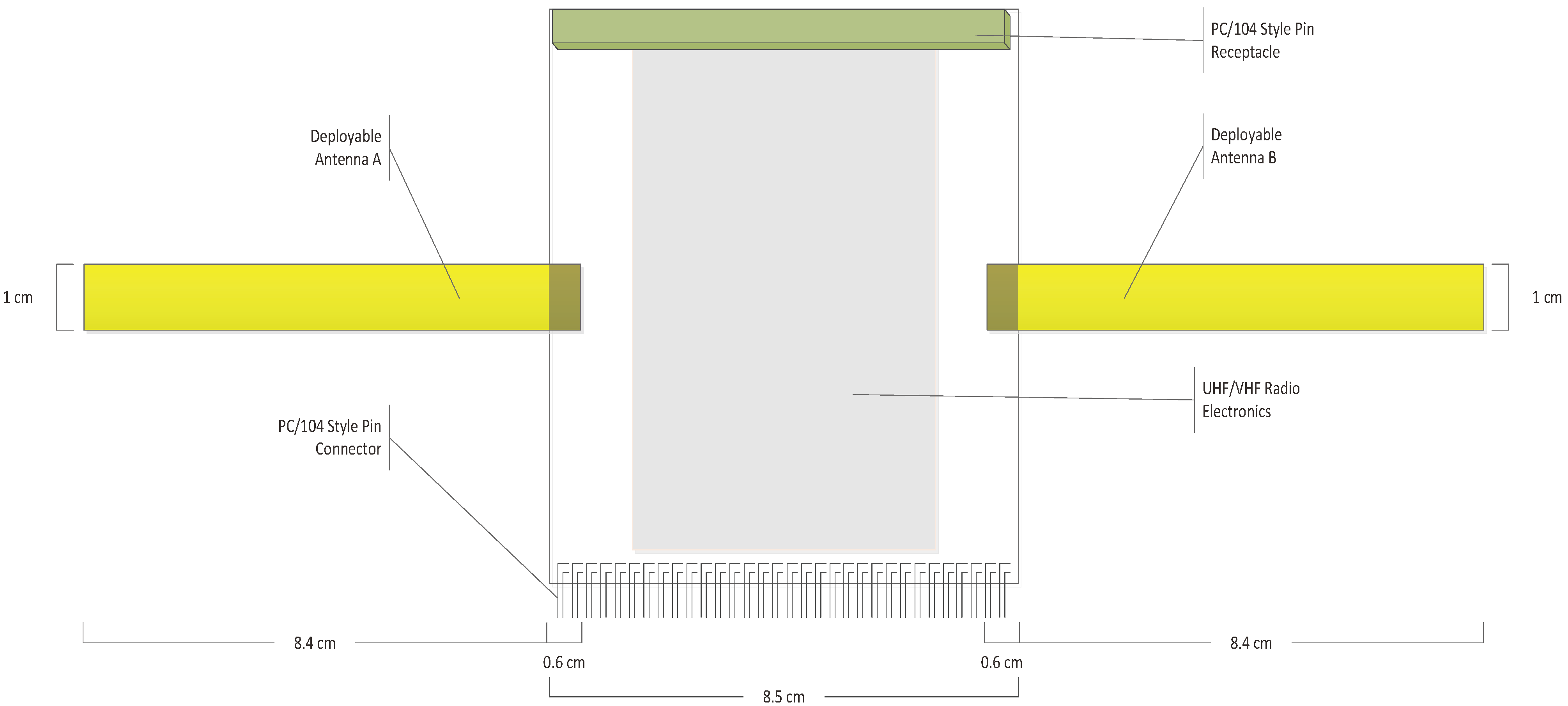
The communications system for the OpenOrbiter spacecraft consists of the TT&C board which includes two deployable antennas (released from packing configuration by neoprene wire). Note that the deployment is actually from the rear (exterior-facing) side of the board, so as to be exterior to the rails (as wrapping around the rails is not allowed by the CubeSat specifications [
24]). This is indicated via shading over this area in
Figure 2. A transmission speed of 1200 baud is presumed. This is based on the 16.8 cm
2 of antenna surface from this configuration and presuming a worst-case orbit of 400 km. The ground station configuration for the OpenOrbiter mission is currently unknown; thus this estimate is based on the designs of other previous CubeSats (e.g., Cute-1, UWE-1, GeneSat-1 [
25]).
Figure 2.
TT&C Board Antenna Configuration.
Figure 2.
TT&C Board Antenna Configuration.
8.5. Onboard Processing Design, Software and Operations
This section presents the design, software and operating plan for the OpenOrbiter spacecraft. The spacecraft autonomously executes ground controller requests, performing onboard task decomposition into specific jobs that must be performed (possibly across multiple orbits) for task completion.
8.5.1 Onboard Processing Hardware Design
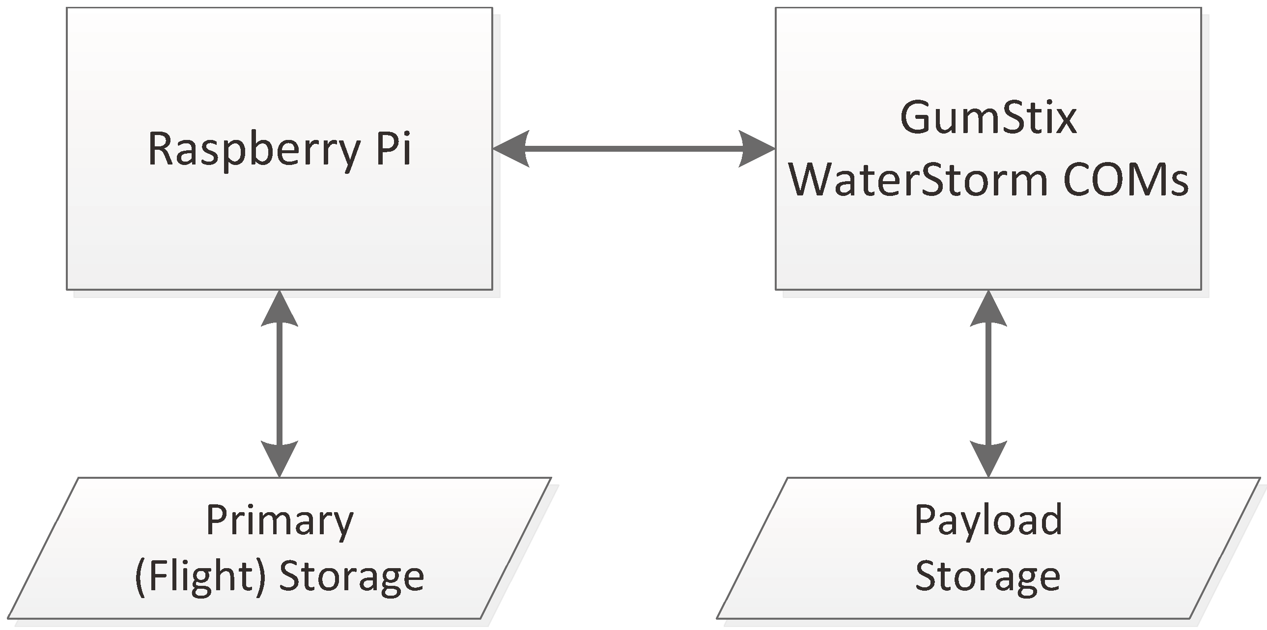
The onboard processing system on OpenOrbiter consists of two computers working in tandem. The flight computer, which will run the operating software for the spacecraft, is always on and runs on a low-cost Raspberry Pi computer. Spacecraft, such as OpenOrbiter, with significant processing requirements can add to the OPEN base design of the Raspberry-based onboard processing. OpenOrbiter has selected to use GumStix WaterStorm COM units for its payload processing. Separate storage exists on both the Raspberry Pi and the GumStix WaterStorm COM units. On OpenOrbiter, the payload processing unit will only be powered on when a job is being run on it.
Figure 3 depicts the configuration of onboard processing for OpenOrbiter.
Figure 3.
Onboard Processing Separation Between Flight and Payload Processing Units.
Figure 3.
Onboard Processing Separation Between Flight and Payload Processing Units.
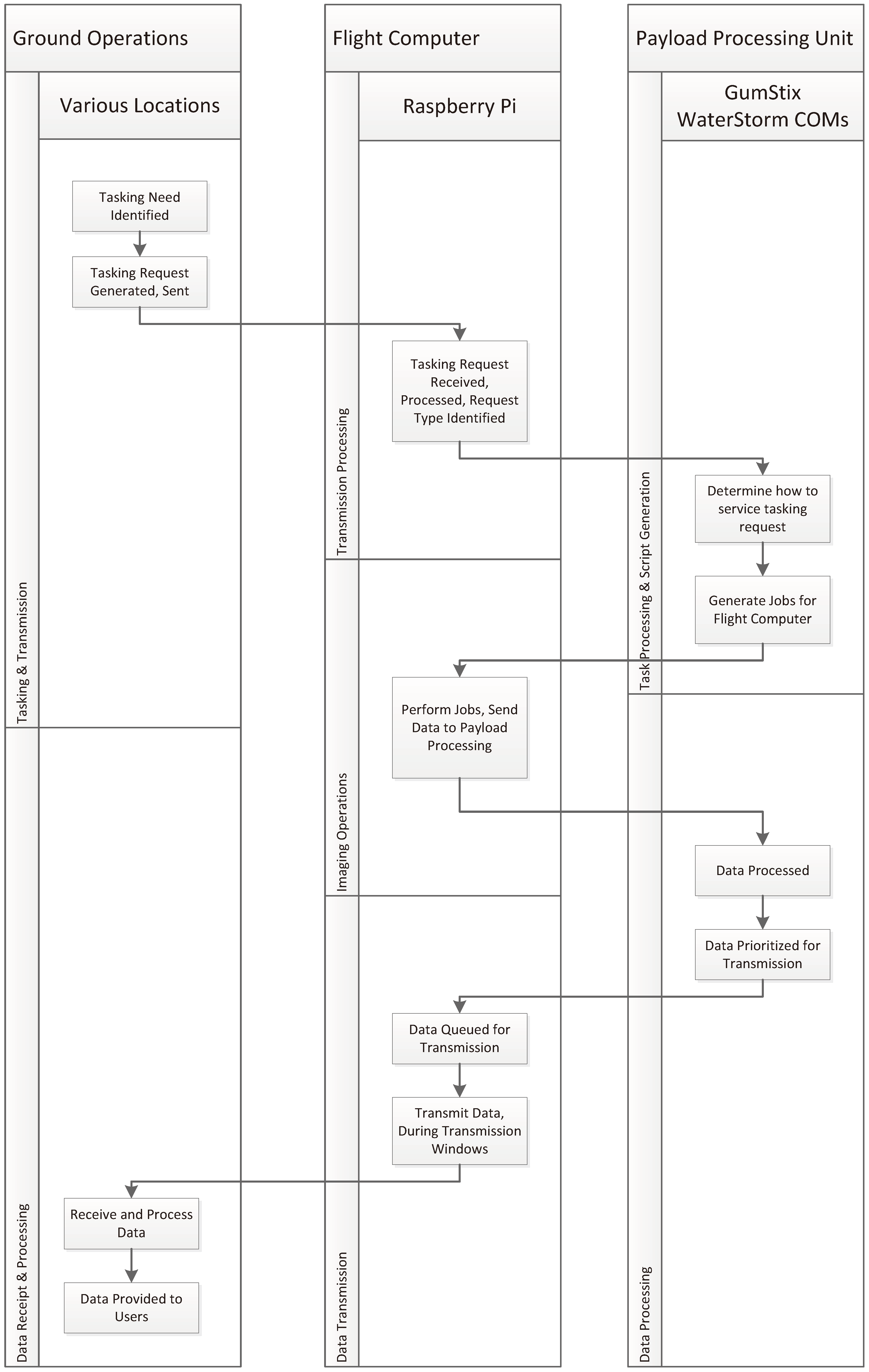
8.5.2 Onboard Computing System Operations
The operations cycle for OpenOrbiter starts with the identification of a tasking need by ground controllers. The controller enters this tasking need into the ground station software which evaluates it for compatibility with current tasks and spacecraft capabilities. The tasking request is then sent as a message to the spacecraft and received and processed by the flight computer. Some requests (e.g., the execution of a specific literal command) are processed directly by the flight computer. Tasking requests for payload operations are sent to the payload processing unit where they are decomposed, based upon task requirements and existing pending jobs, into a set of jobs to be executed by the flight computer. These jobs are then sent back to the flight computer, which performs them and, when they are completed, sends the data to the payload processing unit for selected processing actions. The processed data, possibility stamped with a transmission priority, is sent back to the flight computer and queued for transmission to the ground. During a transmission window, this data is sent back to the ground station where it is received, supplemental processing is performed and it is sent to its requesting-users.
Figure 4 depicts the system operations of the OpenOrbiter mission.
8.5.3 Ground Station Software
An understanding of the operations of the ground station is beneficial to understanding the operations of the spacecraft.
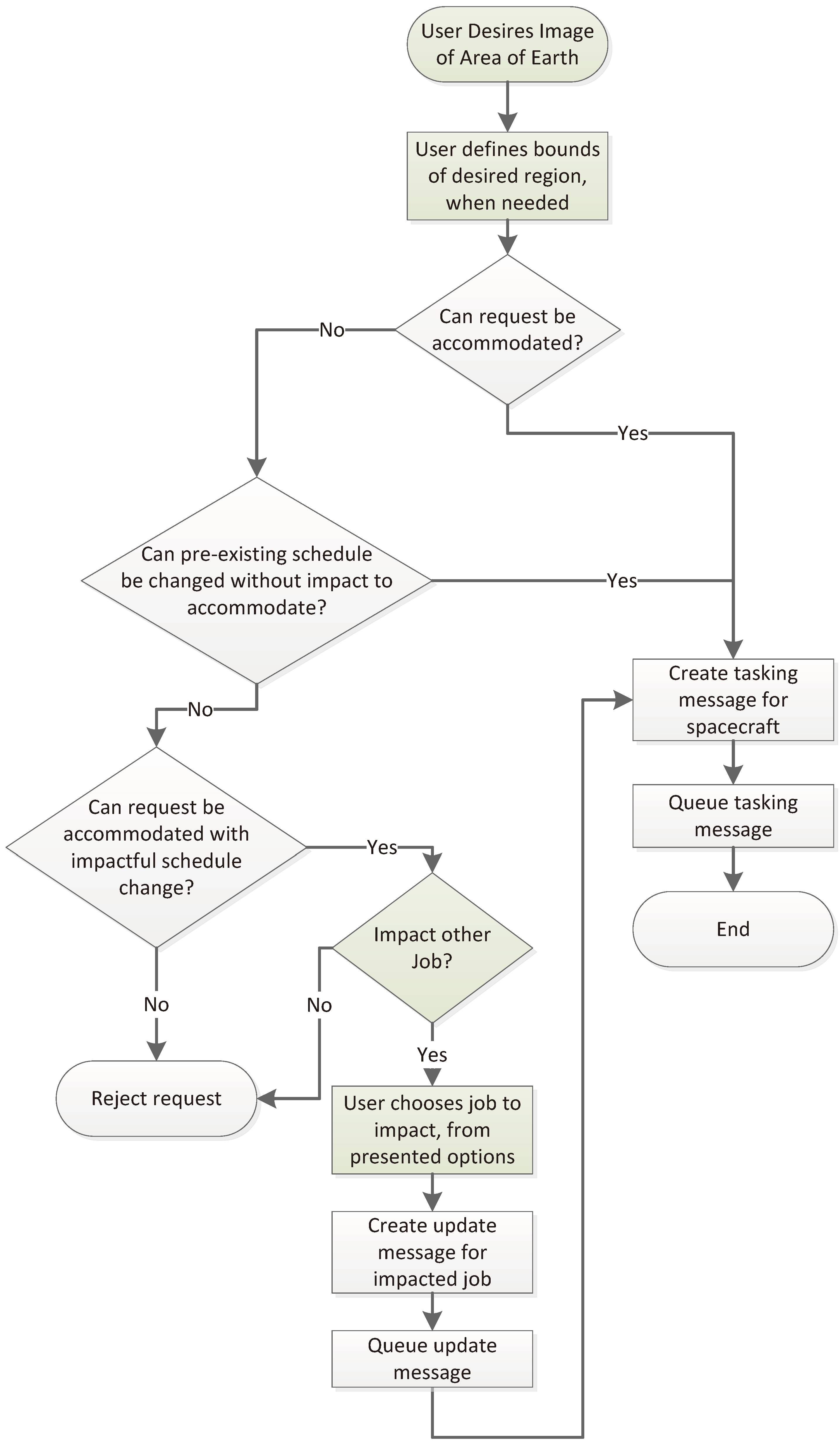
Figure 5 depicts the logic of the tasking process of the ground station software.
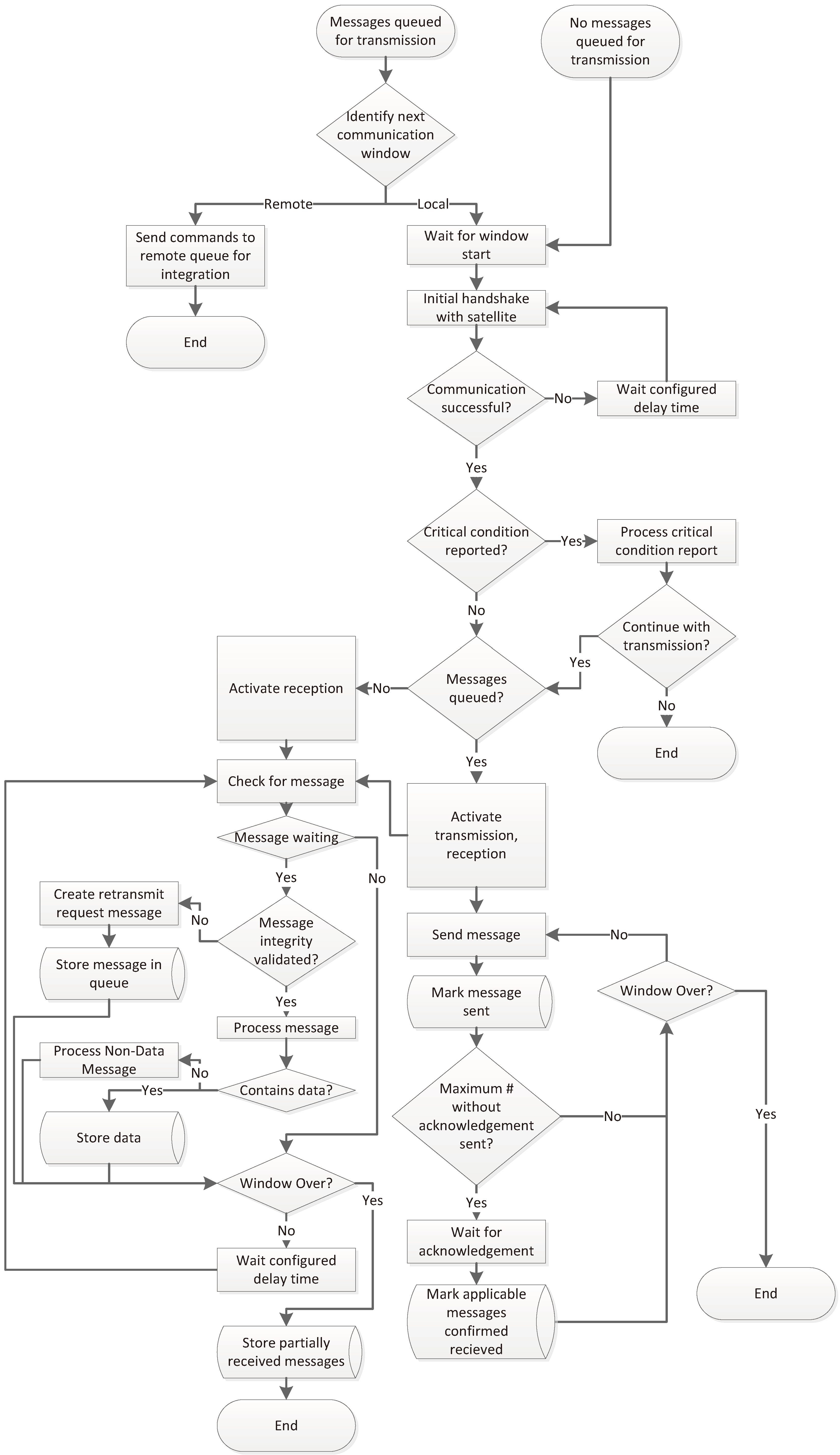
Figure 6 depicts the logic that applies to the message transmission and receipt functionality of the ground station.
The tasking process begins with a user tasking request. These requests are validated to see if they can be accommodated within existing schedule constraints. Those that cannot be integrated into the schedule trigger a check to see if a non-impactful change (e.g., one that does not violate the constraints of another job) can be made to allow it to be completed. Finally, if job satisfaction via a non-impactful change cannot be accomplished, the user is prompted to decide whether authorizing an impacted change is desirable. If so, the user is presented with possible jobs to impact, and must select one or more to terminate or reschedule.
The transmission process is initiated when a message (e.g., a tasking request) is queued for transmission or when a window occurs, where downlinked data and telemetry could be received. The next available transmission window is identified (which could, in a multi-ground station configuration be either a local communications opportunity or an opportunity at a remote station). In the case where the next opportunity is at a remote station, the messages are sent to the remote station (which completes the remainder of this process locally). Irrespective of whether messages are queued to be sent or not, a ground station will wait for the start of the next scheduled (based on orbital projections) communications window.
Each window begins with an initial handshake message exchange between the spacecraft and the ground station. If this cannot be completed at the scheduled time, the ground station waits a configurable delay period and re-attempts the handshake; this will continue until communication is achieved or the window expires. If the handshake is successful, the ground station processes the initial telemetry from the spacecraft, which would include any critical condition reports, if applicable. If no critical condition reports are received or they do not require a change to the communications window plan, transmission (if there are queued messages) and reception are initiated.
Throughout the window, queued messages (if they exist) are sent and received by the ground station. For outbound messages, the message is sent, marked as sent and, as acknowledged, marked as acknowledged. Data is received, checked for integrity (a resend request is triggered if the integrity check fails) and processed and stored. This continues until the transmission window concludes.
8.5.4 Operating Software
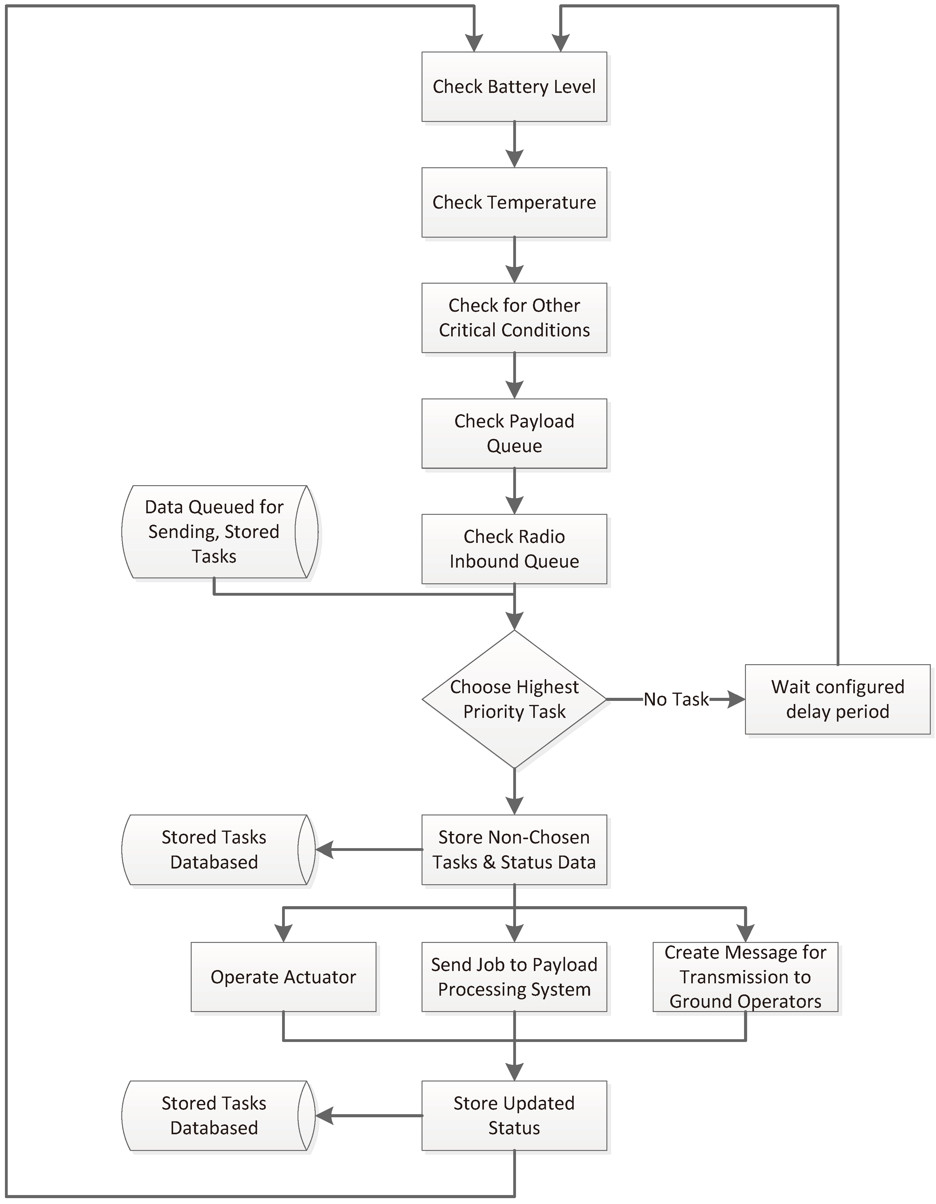
The operating software controls the minute-to-minute operations of the spacecraft. It is based on a loop which begins with, during each iteration, critical status indicators and queues being checked. Then a task (with the highest priority of those pending) is selected for performance (note that it is potentially possible that multiple tasks could be selected for performance in parallel). All non-selected items retrieved from queues and battery, temperature and other indicator values are stored in the onboard database. If no tasks are pending, the system waits a pre-configured period of time and then restarts the loop.
Figure 4.
Software Operations.
Figure 4.
Software Operations.
Figure 5.
Ground Station Tasking Flow Chart.
Figure 5.
Ground Station Tasking Flow Chart.
Figure 6.
Ground Station Communications Flow.
Figure 6.
Ground Station Communications Flow.
Figure 7.
Operating Software Flow.
Figure 7.
Operating Software Flow.
If tasks are present, the selected task is performed, via sending a command to an actuator controller, sending a job to the payload processing system or creating and queuing a message for transmission to the ground station. The status of the task performed is updated, and the loop restarts.
8.5.5 Payload Software
The payload software performs two primary functions. First, it is used to decompose a task into a series of jobs that can be executed by the operating software running on the flight computer. Second, it performs processing of the data collected.
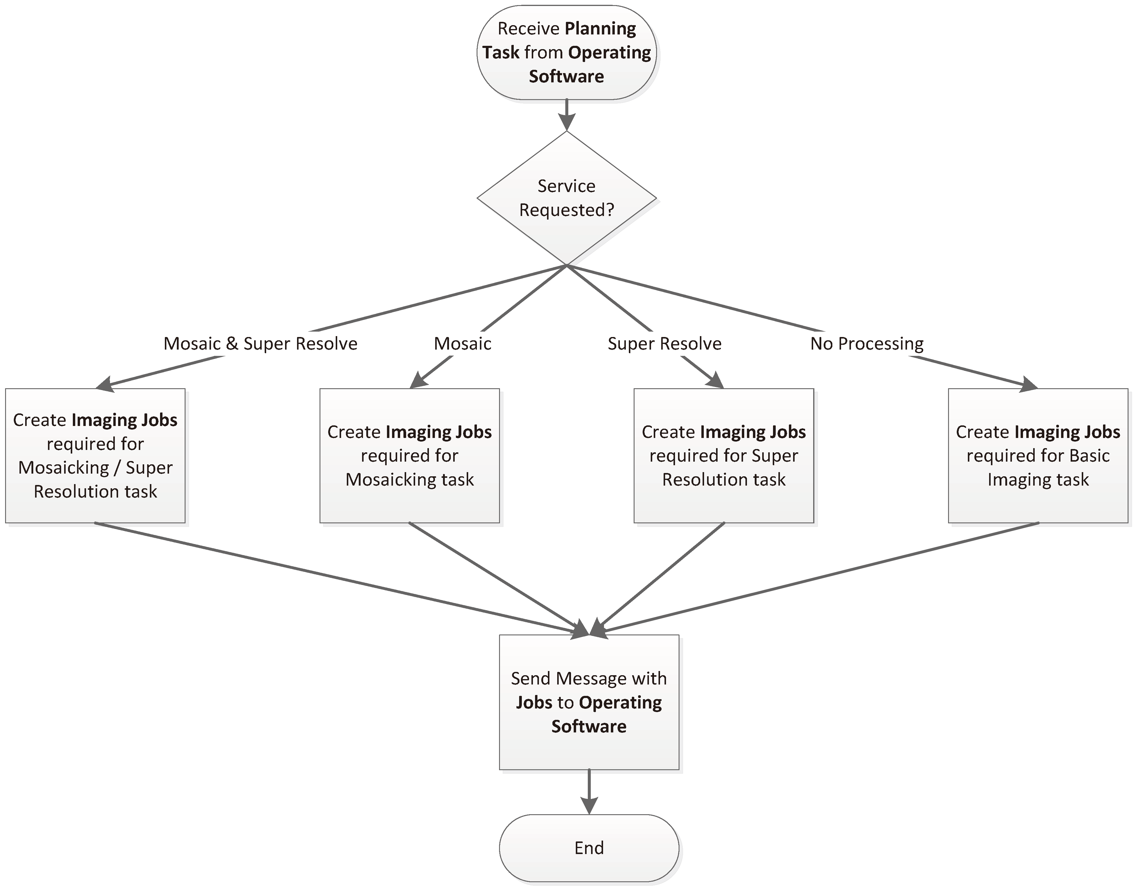
The planning task flow, which is depicted in
Figure 8, begins with the receipt of a planning task from the operating software. This task request may require data collection only or data collection and processing. A set of jobs (including, if applicable, jobs to send the payload software a processing task) is created for the planning task and sent back to the payload software. Imaging jobs include a specific time, attitude and other parameters that the operating software requires to capture the required images.
Figure 8.
Payload Software Planning Task Flow.
Figure 8.
Payload Software Planning Task Flow.
The payload software processing function also begins with a call from operating software. The payload software processing function can be called when data collection for a task is completed. Alternately, it may be used to re-process (or perform alternate processing on) pre-existing imagery.
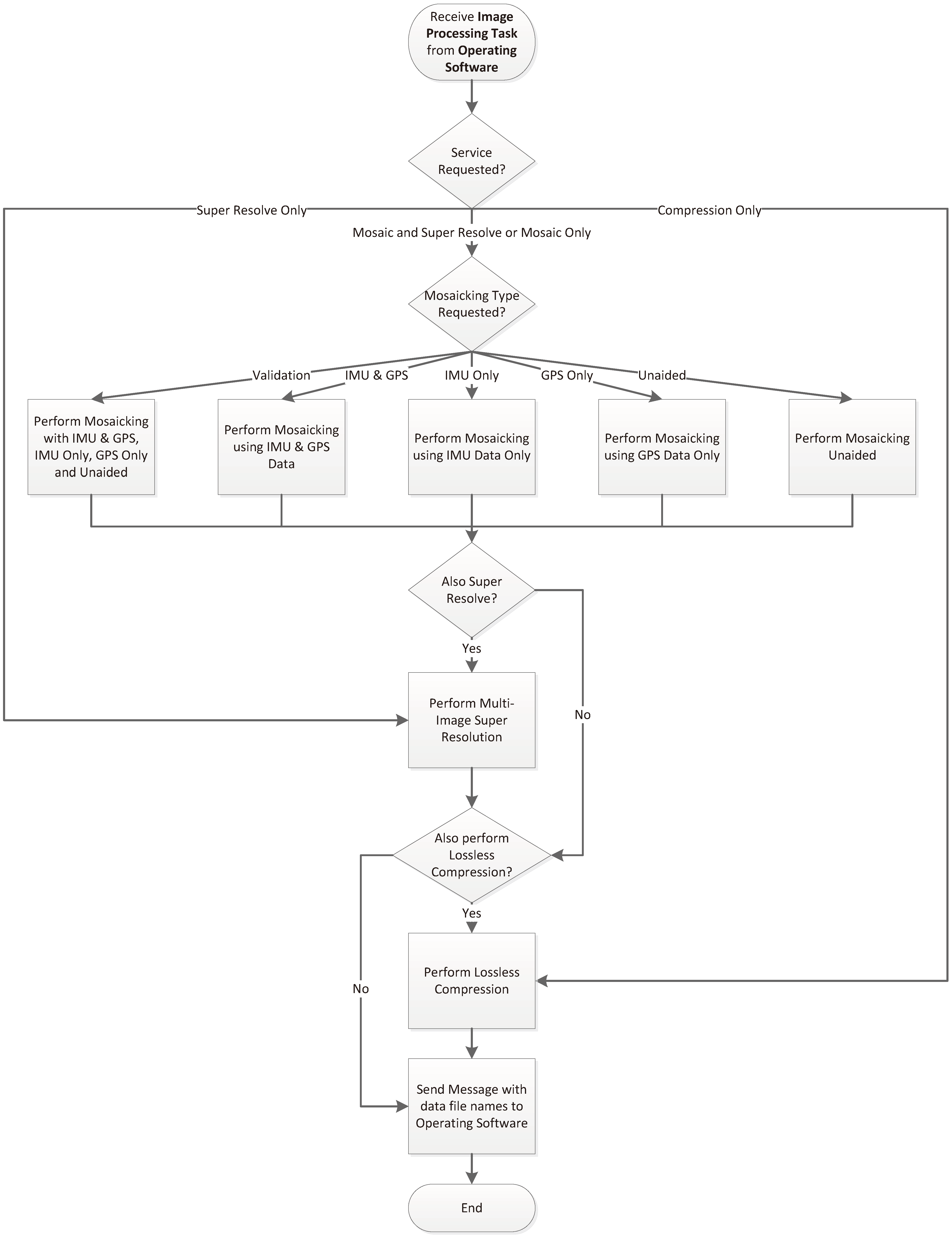
When initiated by the operating software, a service request is included. This includes both the type or types of services to perform and specific service performance parameters. In this case, the most important parameter is what data to utilize when performing mosaicking. One key technical objective of this mission is to determine how valuable inertial measurement unit (IMU) and global positioning system (GPS) data is to optimizing mosaicking. Thus, mosaicking can be performed unaided, with IMU and GPS data, with IMU data only or with GPS data only. A validation mode, which performs all four types of mosaicking for comparison, is also included. Super resolution (image resolution enhancement) can be utilized in conjunction with mosaicking or on its own. Similarly, image compression can be utilized with mosaicking and super resolution, mosaicking, super resolution or on its own. The filenames for the resulting files are sent back to the operating software for retrieval and transmission to controllers, when completed.
Figure 9 depicts the processing function’s operations.
Figure 9.
Payload Software Processing Task.
Figure 9.
Payload Software Processing Task.
8.6. Open Spacecraft Design
The OpenOrbiter spacecraft implements the OPEN layout which places the subsystem/payload boards around a central payload area. This configuration provides room for four boards with a volume of 154.5 cm3 each, a payload area with an approximate volume of 250 cm3 and 57.5 cm3 of battery space.
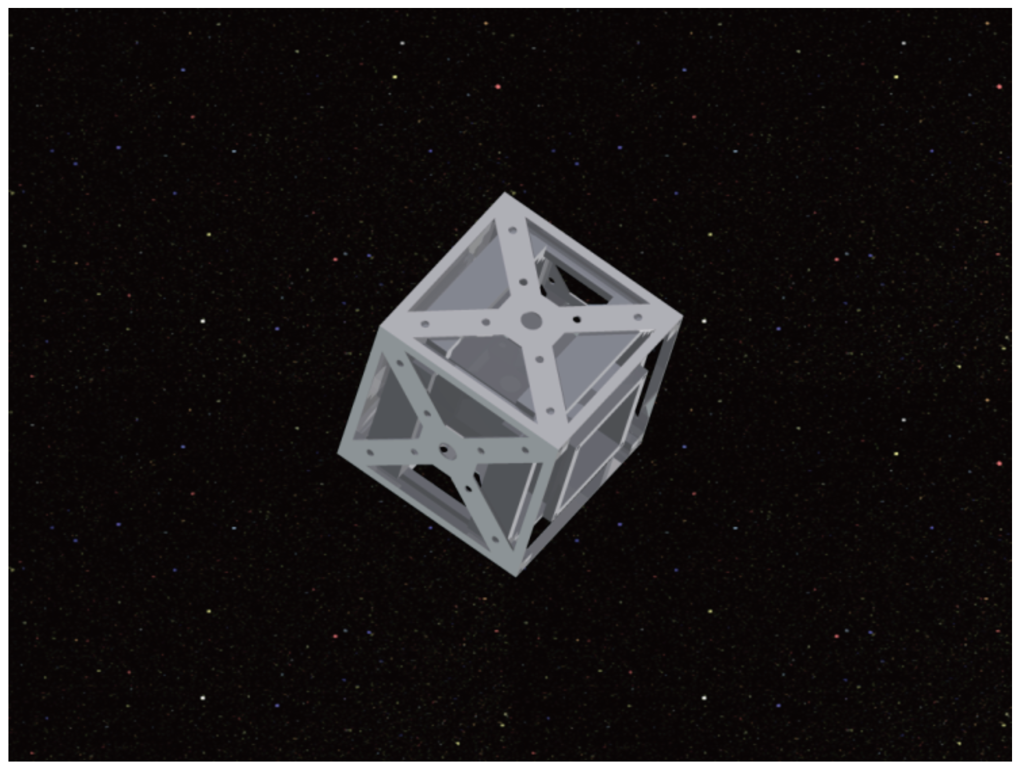
Figure 10 shows an exploded view of an initial CAD model of the spacecraft, which is useful for illustration purposes, as it shows the notion of the board mounts around the central payload area. This model depicts ‘dummy’ boards that might be used to support a component that didn’t interconnect in to the PC/104-compliant bus. The exterior structure has been changed somewhat in the final OPEN version; the cross-supports have been determined to be extraneous and have been removed. This is difficult to interpret, visually, so this diagram has been shown to illustrate the base concept (in addition to demonstrating the design process that was undertaken). The payload area will be used to house an optical camera payload, for the OpenOrbiter Mission.
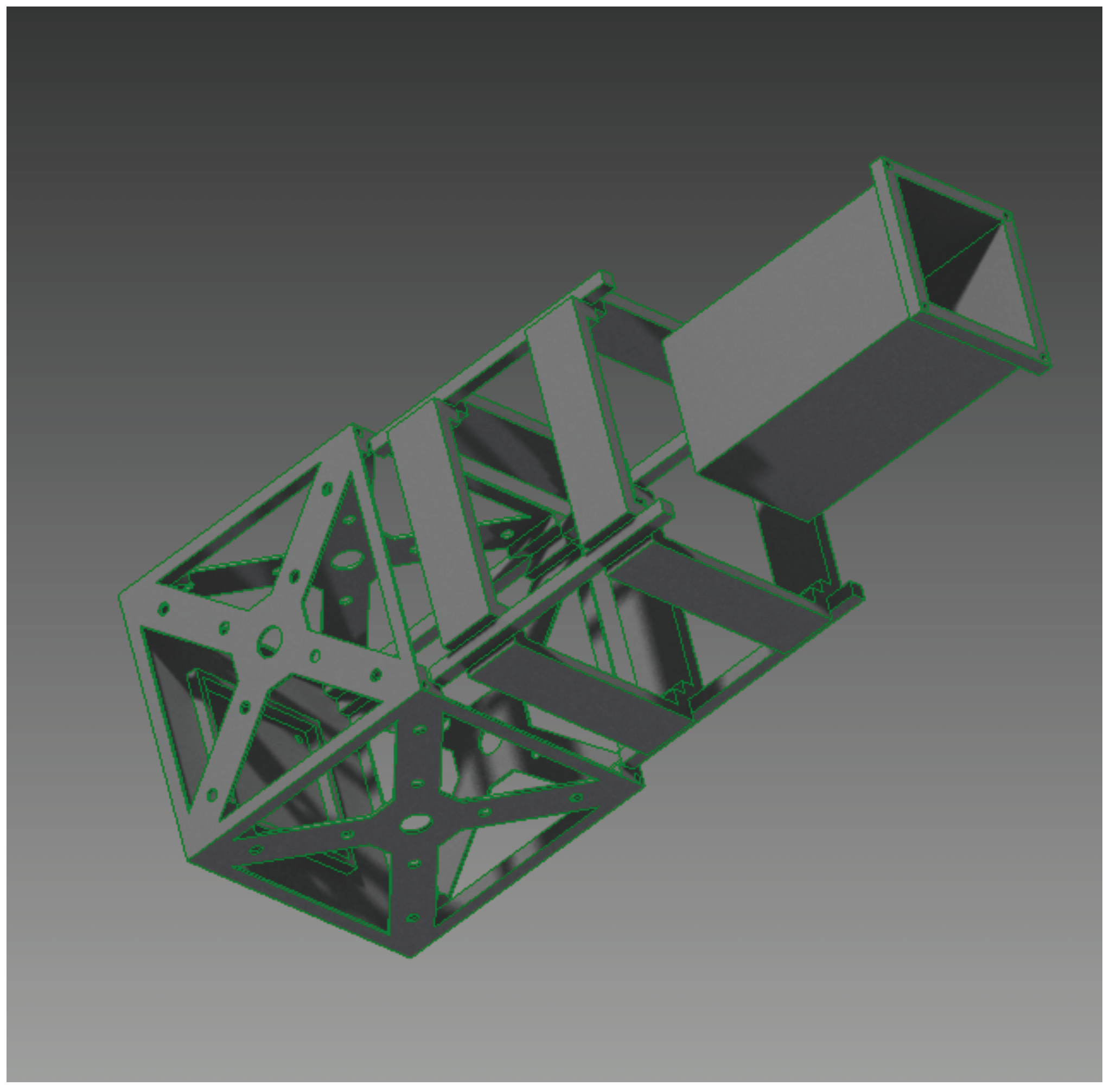
Figure 11 shows the assembled version of the early CAD model of the OpenOrbiter spacecraft.
Figure 10.
Exploded View of Computer Board and Payload Support Structure.
Figure 10.
Exploded View of Computer Board and Payload Support Structure.
In addition to innovation in structure and layout, the spacecraft will feature an electronic stacking scheme (without a requirement for physical stacking) which allows the computer boards and components to be placed anywhere within the spacecraft and still correctly interface with each other. This removes the limitations placed on the layout by previous physical stacking methods while maintaining a level of backwards compatibility, should the designer desire to use boards designed for stacking (with an adapter) or utilize a more traditional stacking method in one area of a multi-unit spacecraft. The board supports for this stacking scheme are shown in
Figure 1.
Figure 11.
CAD Diagram of OpenOrbiter Satellite Internal Structures.
Figure 11.
CAD Diagram of OpenOrbiter Satellite Internal Structures.
8.6.1. Subsystem/Payload Board Specification
The OPEN framework defines a standard board configuration. This is shown in
Figure 12 and
Figure 13. The board (shown in
Figure 12) includes a PC/104-compliant pin set on the bottom and a receiver on the top. The board slides into the posts shown in
Figure 15. The pins on the bottom of the board seat into the receiver base, shown in
Figure 14. The board is 85 mm tall and 85 cm wide. This width allows the board to fit the PC/104 connector (81.79 mm wide) and also fit within the CubeSat volume limitations.
To accommodate the boards fitting in the square pattern depicted in
Figure 17, a reduced-height area has been designated on the sides of the boards. This is shown in
Figure 13. For the front (interior) of each board, the first 5 mm on each side is required to have no raised components (PCB circuit printing can be utilized, as long as suitable contact protection is implemented between the board and the rails). The next 10 mm on each side has a maximum height of 5 mm. The center area on the front (55 mm in width) is allowed to reach 18 mm in height. The rear (exterior) of the board has a 5 mm no-raised-component area on each side. The rest of the board (75 mm in width) has a maximum height of 8 mm. This area protrudes beyond the side rails, as shown in
Figure 17.
Figure 12.
Diagram of OPEN Board Specifications implemented and demonstrated by OpenOrbiter.
Figure 12.
Diagram of OPEN Board Specifications implemented and demonstrated by OpenOrbiter.
Figure 13.
OPEN/OpenOrbiter Board Clearances (top view).
Figure 13.
OPEN/OpenOrbiter Board Clearances (top view).
8.6.2. Subsystem/Payload Board Receivers
The configuration of the OPEN base plate allows four OPEN-compliant boards to be incorporated into the spacecraft, simultaneously. This base plate configuration, which also leaves the requisite 5 cm × 5cm payload area clearance, is depicted in
Figure 14. A top plate, not shown, provides the other aspect of the electrical stacking (without requiring physical stacking); the two plates (interconnected via wires run adjacent to the corner posts) and the corner posts are the key structural members of the spacecraft.
Figure 14.
Receiver (bottom face) plate for OPEN board design.
Figure 14.
Receiver (bottom face) plate for OPEN board design.
8.6.3. Support Structure and Volume Maximization
The OPEN design seeks to maximize the volume available for other subsystems and payload elements while minimizing mass consumed by the structure. The base plates provide structural rigidity; they hold the corner posts in place. The subsystem and payload modules’ printed circuit boards (PCBs) also provides rigidity against certain types of torques.
The corner posts hold the top and base plate together. They also secure the subsystem and payload PCBs via the slot that runs the full length of each corner post. A diagram of the corner post configuration is shown in
Figure 16. Note that while this is oriented for the lower left position, the same part can be utilized (in different orientations) for all four corners. The corner post is affixed with a screw to the top and base plates.
Figure 15 shows the assembled corner posts. It also shows the overhang clearance which is allowed in all areas (per Section 2.2.6 of [
24]), except for the corner posts, which must be in direct contact with the P-POD rails. The corner posts exceed the minimum required width of 8.5 mm (per Section 2.2.9 of [
24]). They must also have their outward-facing corner rounded to a radius of at least 1 mm (per Section 2.2.11 of [
24]), be composed of aluminum 7075 or 6061 (per Section 2.2.19 of [
24]) and be hard anodized to preclude cold welding with the P-POD rails (per Section 2.2.20 of [
24]).
Figure 15.
OPEN / OpenOrbiter Corner Post Configuration.
Figure 15.
OPEN / OpenOrbiter Corner Post Configuration.
Figure 16.
Example Corner Post Schematic (lower left corner shown).
Figure 16.
Example Corner Post Schematic (lower left corner shown).
8.6.4. Integration of Boards & Battery Area
This section considers the integration of boards and batteries into the spacecraft design. The corner post configuration (shown in
Figure 15) and receiver (shown in
Figure 14) are integrated to produce the bottom part of the CubeSat structure. A top plate, which secures the posts in place and connects to the top of the boards (not shown) completes the design.
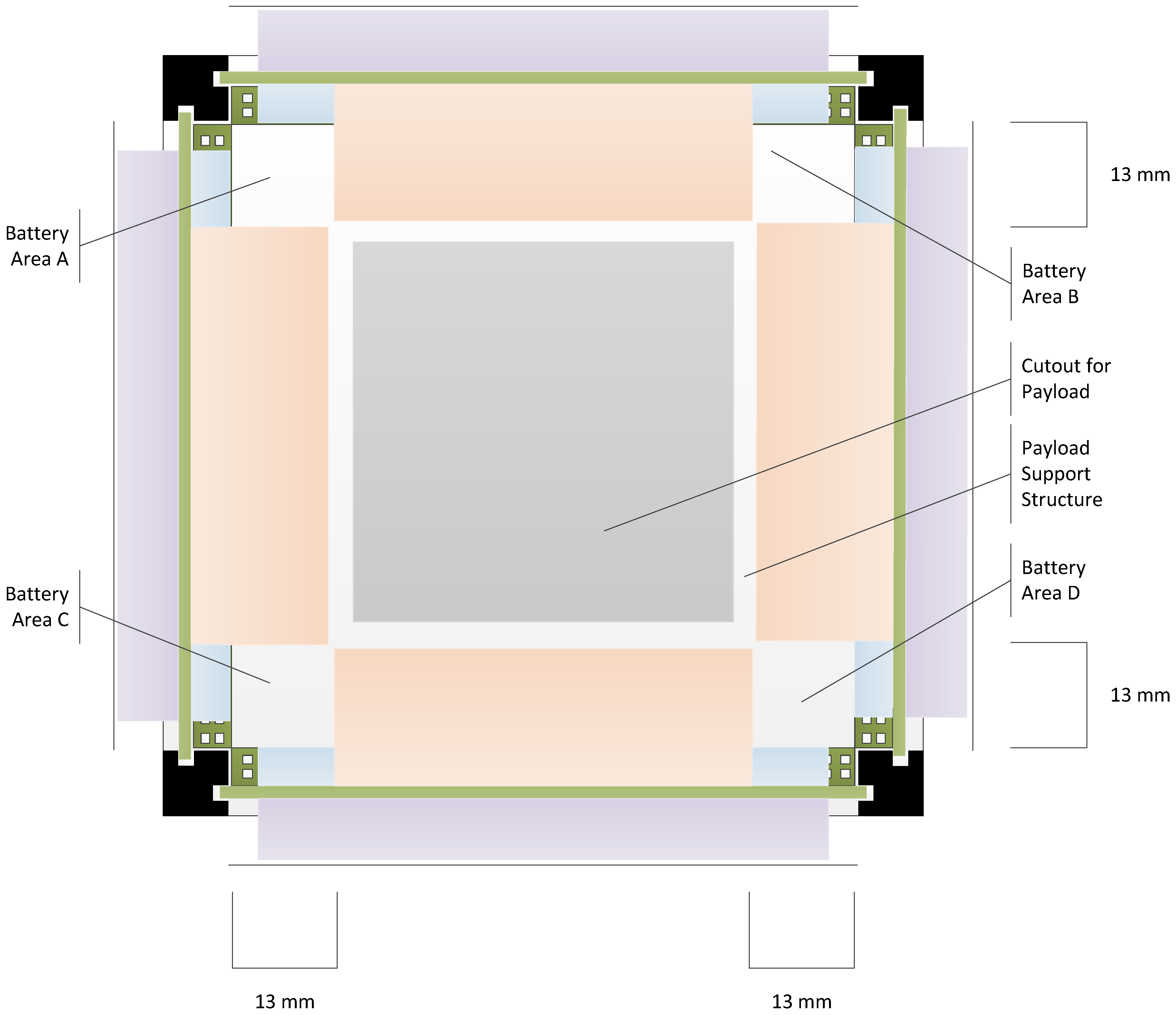
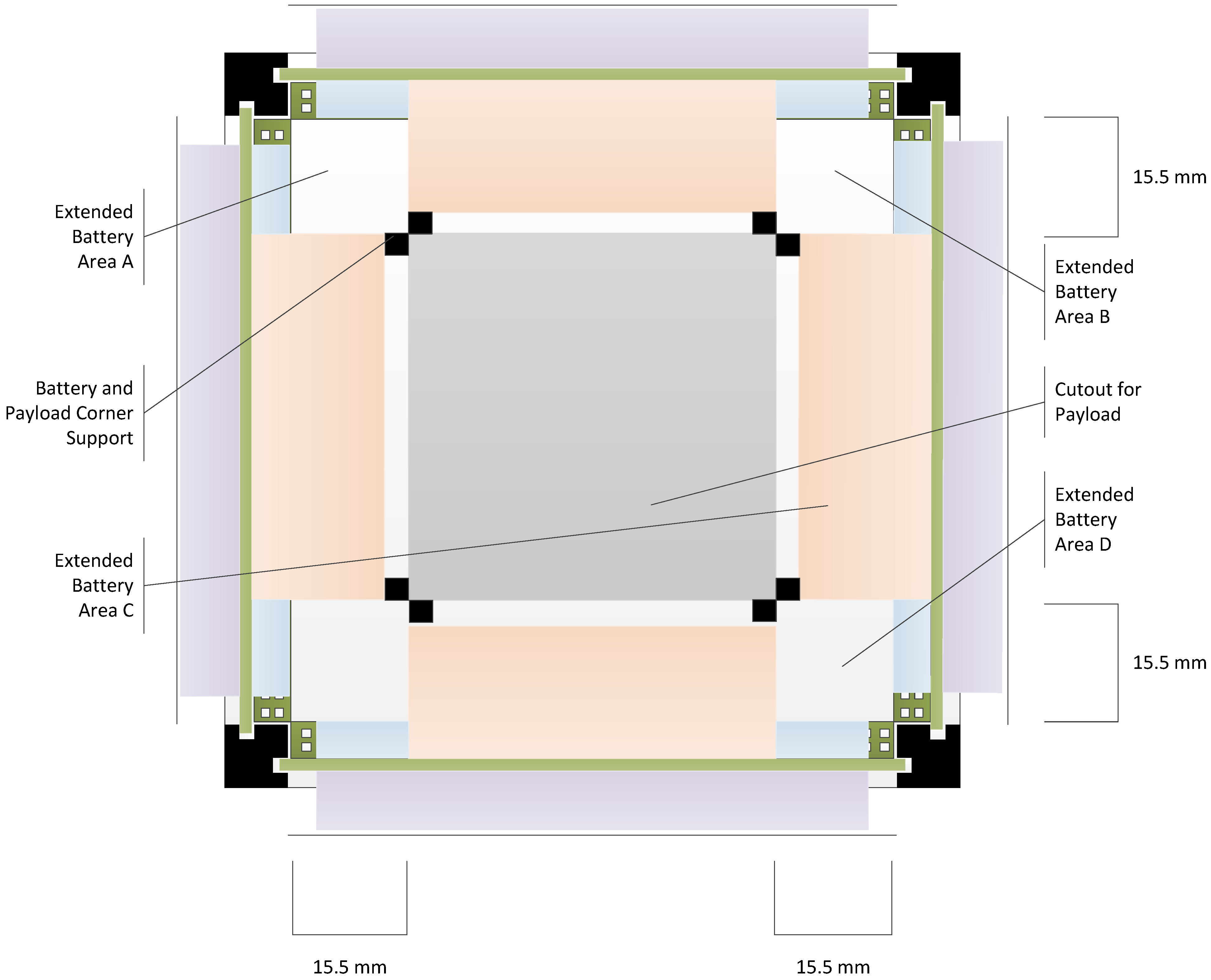
The base configuration of the OPEN design, shown in
Figure 17, allows 14.4 cm
3 of battery space in each corner. An alternate supported configuration moves 1.5 mm of space on each side of the payload/subsystem boards from the full-height to the reduced-height area and converts this space into additional battery area. To support this, two posts are used on each corner (leaving the corner-square unoccupied), instead of a continuous structure. This approach increases the battery volume to 20.4 cm
3, per corner (an increase of 6 cm
3 per corner or 24 cm
3 for the whole spacecraft—more than the amount of volume of a fifth battery). For boards that do not need to fully utilize the full-height area, the reduced full-height area may not be impactful on the boards’ functionality.
Figure 18 depicts this alternate configuration.
Figure 17.
Overlay of Board Clearance Diagram on combined corner post/receiver and base plate diagram.
Figure 17.
Overlay of Board Clearance Diagram on combined corner post/receiver and base plate diagram.
Figure 18.
Alternate Payload Support Configuration with Extended Battery Area.
Figure 18.
Alternate Payload Support Configuration with Extended Battery Area.
9. Payload Support
The OPEN framework is designed to provide flexibility for the payload area. It allows (for a 1-U CubeSat, a volume of 250 cm3 (based on dimensions of 5 cm × 5 cm × 10 cm). This maximizes the size of focal length possible for a remote sensing experiment, allows stacking of modules (e.g., a 3-U CubeSat would allow 5 cm × 5 cm × 33 cm for a volume of 835 cm3) and is conducive to placing a propellant tank at the center of mass (obviously decreasing the volume available to payload components).
9.2. Pointing Support
The preliminary ADCS design is based on the University of Surrey’s QB50 ADCS specifications [
26]. A combination of magnetic torque rods and momentum wheels will be utilized. Processing will be performed by the flight computer, removing the need for additional computing capabilities specific to the ADCS system. Based on the projected performance of the University of Surrey’s ADCS unit, pointing accuracy of 1ᵒ is expected for each (x, y, z) axis. Blue Canyon Technologies Flexible ADCS CubeSat Technology (XACT) shows [
27] that even greater pointing accuracy may be possible in a similar form factor; their proposed system targets 0.02ᵒ accuracy.
10. Conclusions and Future Work
This paper has presented the design and development work performed on the OpenOrbiter spacecraft at the University of North Dakota. It has also highlighted critical aspects of this student-driven, student-centered project. Future work will include the completion of design activities, fabrication, integration, testing and orbital operations.

