1. Introduction
In recent years, the demand of renewable energy has increased globally. One renewable energy resource that has not been contributing in a big scale to the world’s energy production so far is wave energy. It has been estimated that wave energy could provide between 1-15 TWh globally [
1]. The problem of keeping large and complex structures out at sea and the maintenance issue could partly be a reason why wave energy has not yet contributed greatly.
A comprehensive description of different wave energy converter technologies is found in [
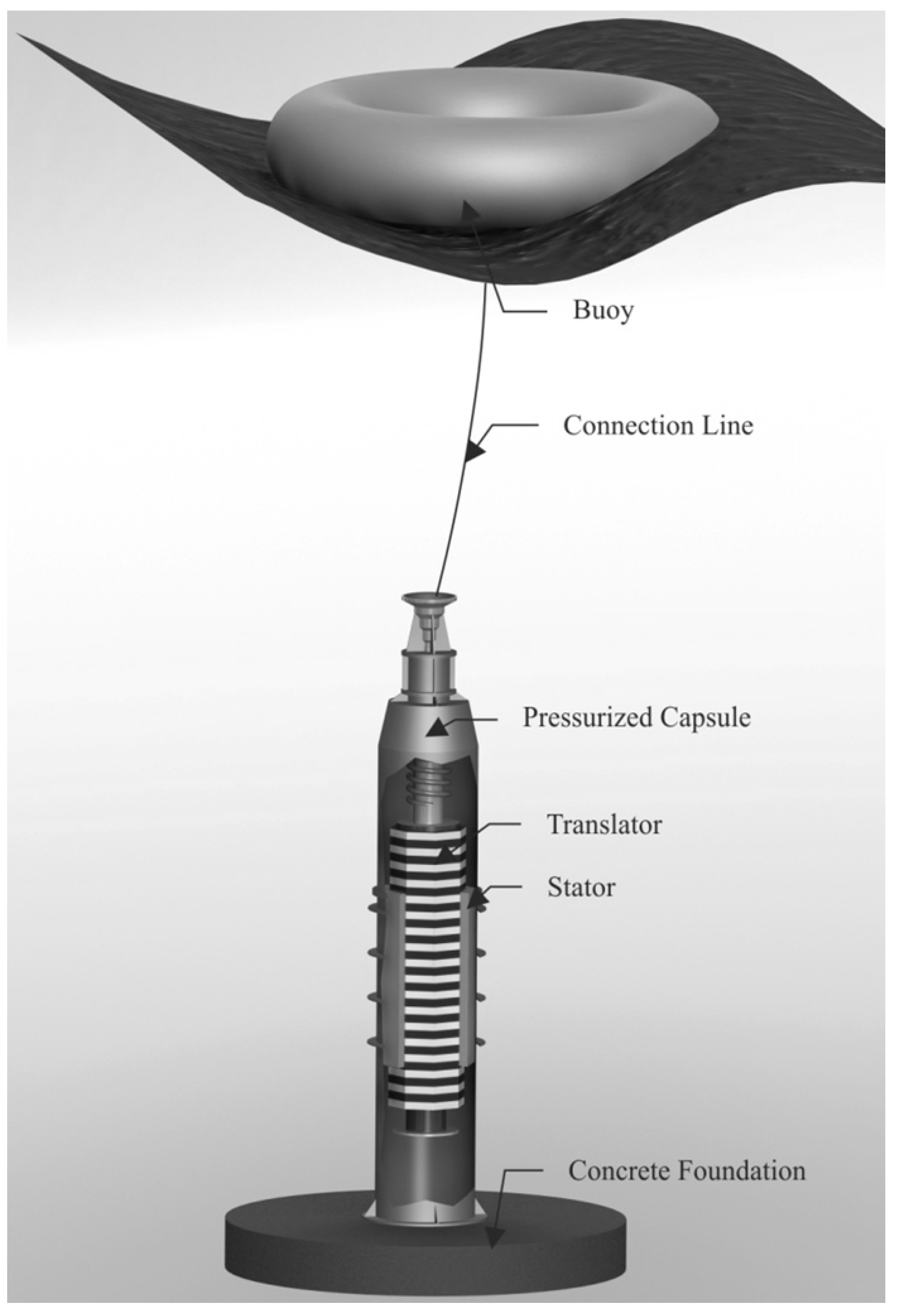
2]. Uppsala University has, with the goal to keep the complexity down, developed a direct driven wave energy converter; see
Figure 1. The linear generator is placed inside a pressurized capsule on the seabed. A buoy on the surface then transfers the motion of the waves through a wire down to the generator, making the translator move in a linear motion up and down. A voltage is induced in the windings of the static stator when the translator (with surface mounted permanent magnets) moves in a vertical direction. The connection line is connected to a piston rod in the linear generator. The piston rod lifts the translator and keeps the capsule sealed by moving through a sealing device.
Figure 1.
The wave energy converter developed by Uppsala University.
Figure 1.
The wave energy converter developed by Uppsala University.
The generator studied in this paper is based on an eight sided stator-translator design
i.e., the generator is octagon shaped. Previous studies have been done on an octagonal linear generator at Uppsala University but for a different power rating and slightly different design [
3]. The translator is 1.5 times longer than the stator with a total number of 53 magnetic poles of which 35 of them are active at any time. Parameters of the generator can be seen in
Table 1.
Earlier generator prototypes developed and tested by Uppsala University were based on a four sided stator-translator design. Further details of these generator designs and offshore experiments can be found in [
4,
5,
6].
Table 1.
Parameters of the generator.
Table 1.
Parameters of the generator.
| Symbol | Quantity | Value |
|---|
| Br | remanent magnetic flux density | 1.4 T |
| Hc | coercive field intensity | 1,115 kA/m |
| hpm | magnet height | 11 mm |
| wpm | magnet width | 47.3 mm |
| g | air-gap | 3 mm |
| wt | tooth width | 9.3 mm |
| ws | slot width | 4 mm |
| ht | tooth height | 9.5 mm |
| hy | Yoke height | 42.8 mm |
| hc | translator core height | 15 mm |
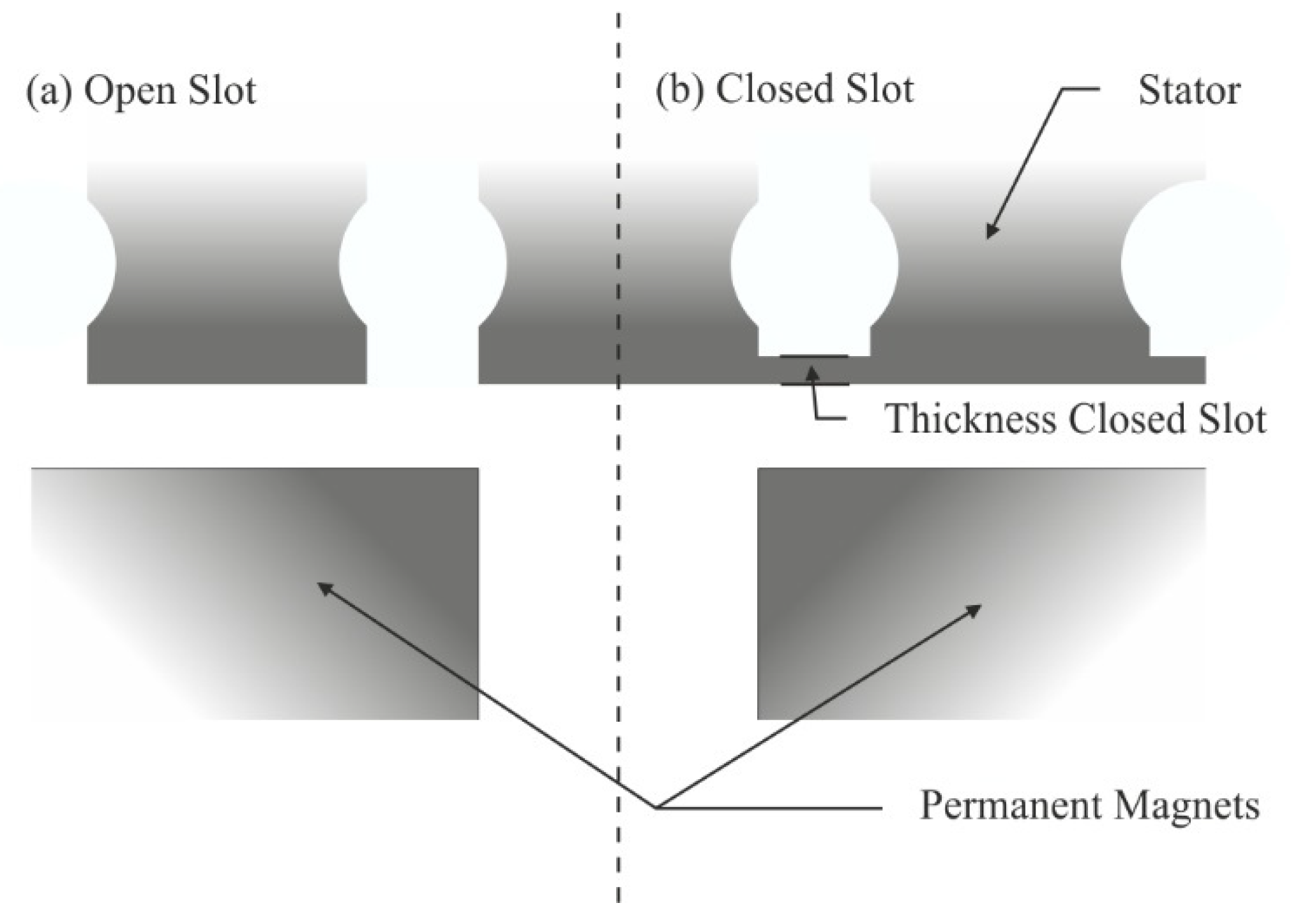
The purpose of this paper is to study the magnetic flux in the generator when the design of the stator is changed. Two different cases are studied, when the generator has open stator slots and when it has closed stator slots. In the closed slots case, the thickness of the slots, see
Figure 2, is varied. It has been selected by keeping a magnetic flux density in the closed slots above 2 T, above the saturation knee point for the electrical steel in the B-H curve. By closing the stator slots, the axial force,
i.e., cogging force, can be reduced [
7,
8,
9,
10] which is seen as one of the goals with closed stator slots. The cogging force gives rise to vibrations [
11] in the wave energy converter which could affect the generator, the sealing,
etc., negatively over time. The importance of minimizing potential problem areas arises from the maintenance issue with the generator kept at the seabed.
Figure 2.
One section of the linear generator showing the difference between: (a) open slot; and (b) closed slot.
Figure 2.
One section of the linear generator showing the difference between: (a) open slot; and (b) closed slot.
Another way to reduce the axial force would be to use a fractional winding. However, this winding configuration could be quite complex and time consuming to produce. With closed slots, an easier winding configuration could be used while still keeping the axial forces down. Moreover, the closed slots keep the winding protected inside the stator which is important both during production of the generator and during operation.
The focus of the study is to analyze the wave shape of the magnetic flux density in the air-gap, which is directly linked to the cogging force, and the leakage flux through the stator slots.
3. Analytical Model of the Magnetic Flux through the Closed Slot
The stator geometry is designed to guide the magnetic flux around the windings in the stator. When the slots are closed, the magnetic flux can find a short-cut between the teeth. This flux does not surround the windings and is called leakage flux. All magnetic flux that is not contributing to the induced voltage in the windings are leakage flux. By keeping the magnetic flux through the closed slots constant and decreasing the closed slots surface area, the magnetic flux density will increase and at a specific surface area the material in the closed slot will saturate. This means that an increase in magnetic field intensity, H, will not increase the induced magnetic flux density, B.
The relative permeability of the material, μr, will decrease with increasing magnetic field intensity and the reluctance, R, of the material increases.
To keep the area of the closed slots in saturation, the permeability of the material will be close to that of air, which would make the closed slots very similar to the open slots case. By making sharp edges at the corner of the closed slots, see
Figure 2, local saturation points are formed since the flux is concentrated to these areas [
8]. These local saturation points are of importance in this paper and can be found in the result section.
For a particular translator position see
Figure 3, an equivalent magnetic circuit presented in
Figure 4 has been derived for the machine by using Ampere’s law. To calculate the peak flux through one closed slot the flux path of two teeth and two magnets are used. The flux from the other teeth will not contribute to the flux leakage through the closed slot at this position.
In
Figure 3, the flux lines for two teeth are illustrated. The flux lines surrounding the windings in the stator are the only ones contributing to the linkage flux; all others are more or less regarded as leakage flux. The flux leakage from the permanent magnets can be divided into two parts as illustrated in
Figure 3, flux leakage between two magnets and flux leakage at the ends of the magnets. The losses are calculated by Equations (3) and (4).
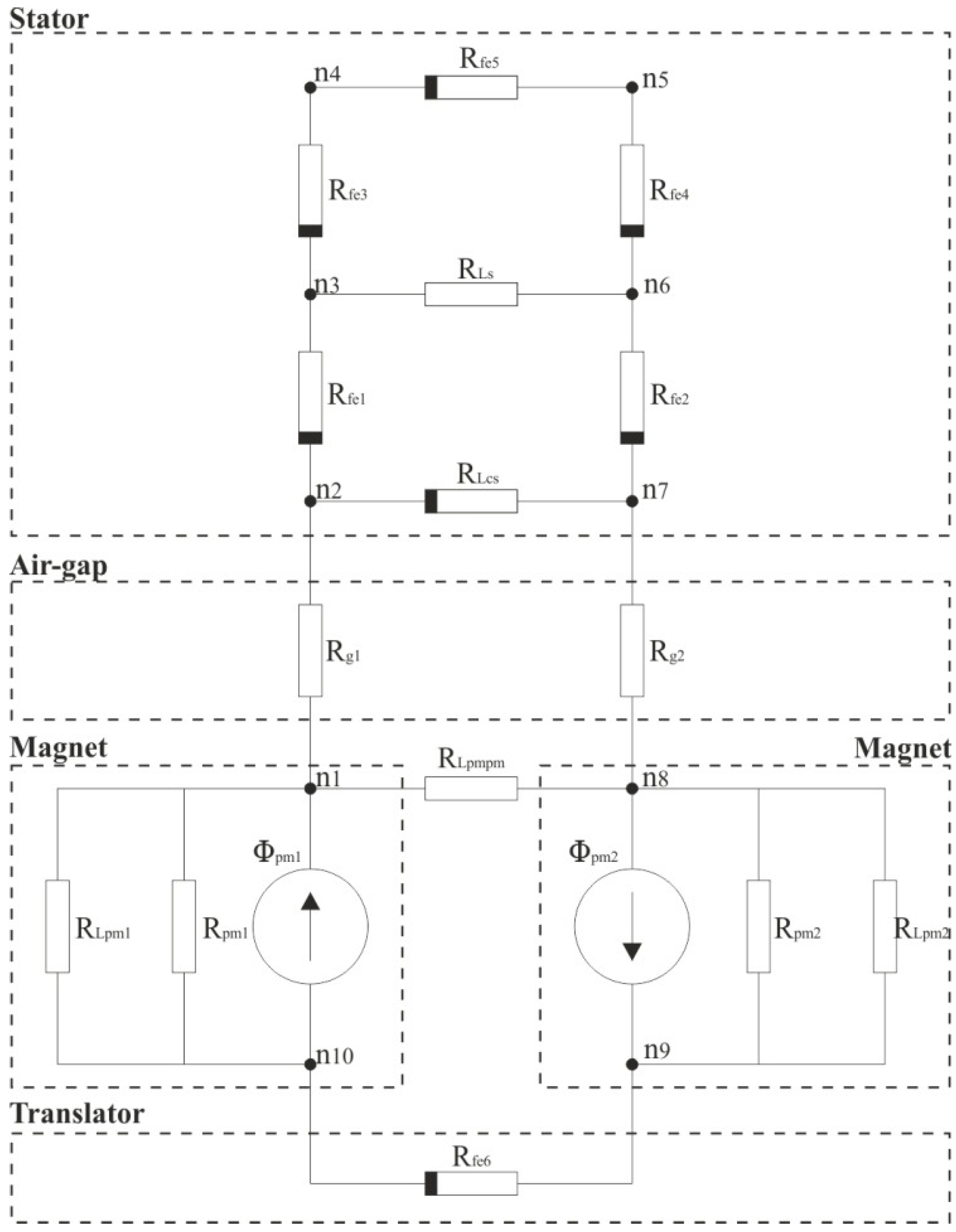
The equivalent magnetic circuit is shown in
Figure 4. It is divided into five parts, the translator core, two magnets, air-gap and the stator core. The non-linear iron parts are highlighted with a thicker black line at the edge. The reluctance in the iron parts are described as
Rfe except for the closed slot which is represented as
RLcs where the
L stands for leakage.
RLpm and
RLpmpm are the reluctance leakage paths for the magnets.
ni are the number of nodes in the circuit where
i = 1 − 10.
Figure 3.
Illustrates two poles of the magnetic circuit and the flux lines between two teeth.
Figure 3.
Illustrates two poles of the magnetic circuit and the flux lines between two teeth.
Figure 4.
Magnetic equivalent circuit.
Figure 4.
Magnetic equivalent circuit.
The analytical model of this machine is divided into several parts and described in the following subsections.
3.1. Permanent Magnets
The permanent magnet can be described as a magnetic potential source with the reluctance:
where
μrec is the recoil permeability of the permanent magnet. The magnetic potential difference from the magnet can be calculated by the following equation:
where
Hc is the coercive field strength of the permanent magnet. The reluctance between the permanent magnets and the translator core, Equation (3), and between two magnets, Equation (4), can be calculated according to [
12] as:
where
wf is the distance between two magnets. Equation (9) is valid for:
The magnetic potential difference from the magnet felt by the stator tooth and the closed slots vary with the position of the magnet and can be expressed as:
where
x is the distance and
wp is the pole width.
3.2. Closed Slots
The flux through the closed slots is bounded to the position of the permanent magnets. Maximum flux through one slot is observed when the slot is positioned between two magnets while the minimum flux condition is encountered when the closed slot is positioned in the center of the magnet. However, when there is a minimum flux through the closed slot, much of the linkage flux will by-pass the slot. So a maximum in saturation in the corner of the closed slots would appear during this time.
The reluctance of one closed slot can be calculated by using the following equation:
where
μcs is dependent on the
B and
H field non-linear behavior.
By calculating the reluctance in the whole circuit, knowing the magnetic potential difference of the permanent magnet, the flux can be calculated through different parts. Moreover, by using the known surface,
A, where the flux is passing through, the magnetic flux density can be calculated. The flux through one closed slot at a particular position is shown in
Figure 3 and is calculated by:
where
α,
β and
γ are given by
and
μi i = 1, 2, 3, 4 are the relative permeability in different parts of the iron,
li is the flux path length and
wi is the width of the flux path.
3.3. Non-Linear Permeability
To calculate the non-linear behavior of the permeability,
μi, in different parts of the iron an expression of the
B(
H) needs to be derived. A modified Langevin expression can be used for this according to [
13].
where
Hi and
Bi is the field intensity respective the flux density at a different parts of the magnetic circuit.
Ms is the saturation magnetization and
a is a material dependent parameter. For each part in the iron the field intensity is iterated by Equation (12) and by knowing the field intensity and flux density the relative permeability is calculated. The values of the different
μi are then inserted into Equation (8) to calculate the magnetic flux and the magnetic flux density.
4. Results
The results in
Figure 5 and
Figure 6 present the magnetic flux density and the cogging force for different thicknesses of the closed slot. In
Figure 7,
Figure 8 and
Figure 9, the focus is on the magnetic flux in the stator. The flux linkage for one phase is presented in
Figure 10.
Figure 11 presents a snapshot of the magnetic flux density distribution in the stator and in
Figure 12 the analytical calculation of magnetic flux through the closed slot is presented.
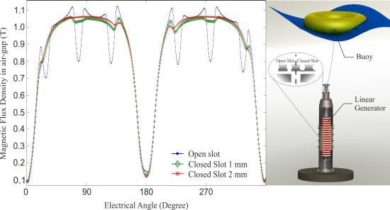
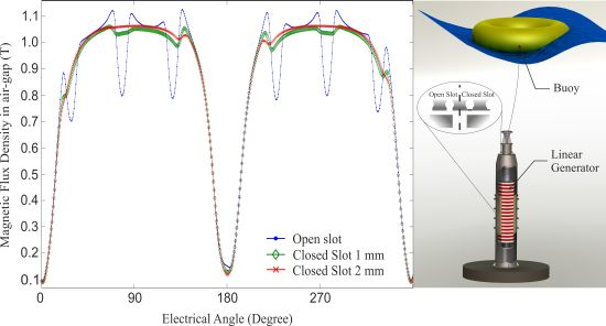
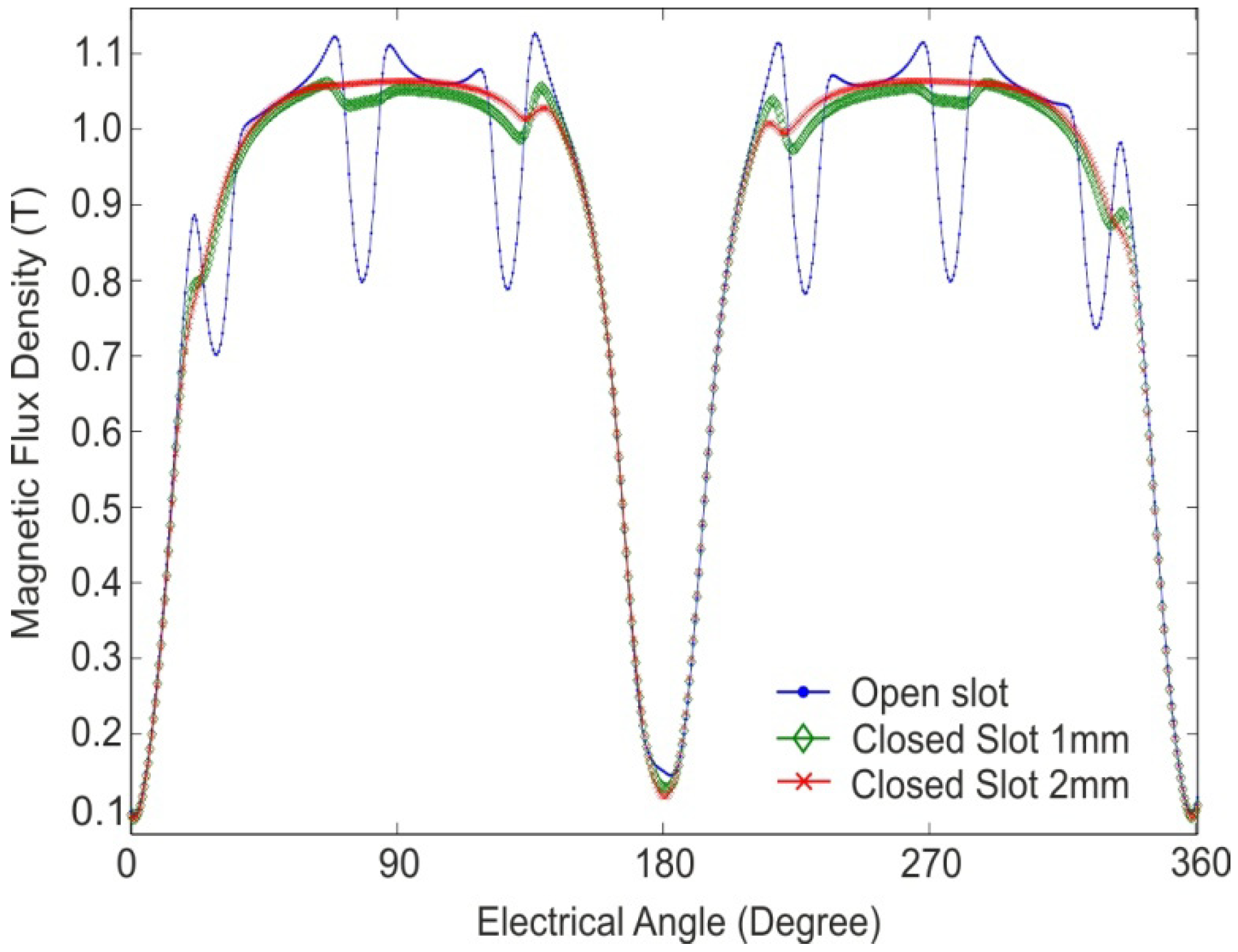
In
Figure 5, the computed results, through FE simulation magnitude of the magnetic flux density in the middle of the air-gap, are plotted over one pole pair. In the magnetic flux density belonging to the open slots, there are larger harmonics compared to the closed slots. The harmonics also decrease when the closed slots have a larger thickness.
Figure 5.
Magnitude of the magnetic flux density in the middle of the air-gap: for open slots (dot); closed slots 1 mm thick (diamond); and closed slots 2 mm thick (cross), simulated over two magnetic poles.
Figure 5.
Magnitude of the magnetic flux density in the middle of the air-gap: for open slots (dot); closed slots 1 mm thick (diamond); and closed slots 2 mm thick (cross), simulated over two magnetic poles.
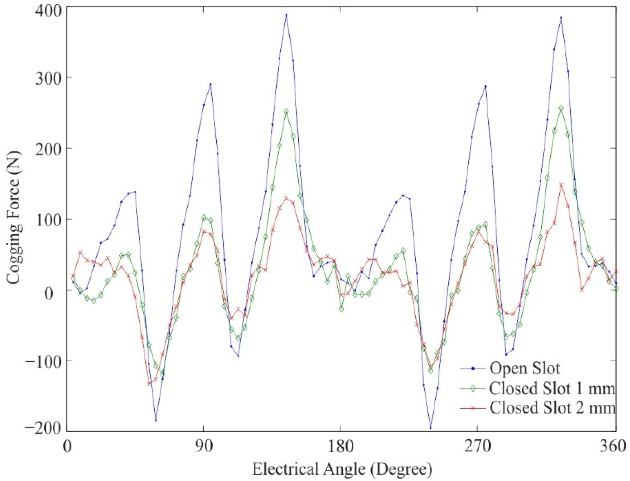
Cogging force integrated over one pole pair for three different cases simulated over 360 electrical degrees is presented in
Figure 6, where the longitudinal end effects are ignored.
Figure 6.
Cogging force over one pole pair during 360 electrical degree for open slot (dot), closed slot 1 mm thick (diamond) and closed slot 2 mm thick (cross).
Figure 6.
Cogging force over one pole pair during 360 electrical degree for open slot (dot), closed slot 1 mm thick (diamond) and closed slot 2 mm thick (cross).
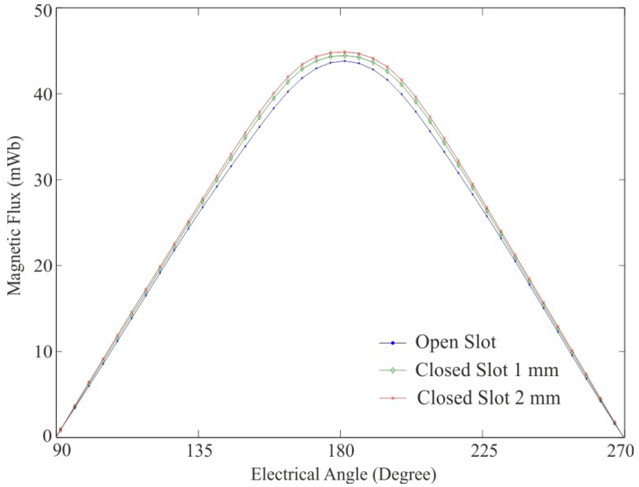
In
Figure 7, a transient FE-simulation during 180 electrical degrees of the magnetic flux, entering the stator for one slot, simulated for three different cases. The closed slot cases show a slight increase in magnetic flux on entering the stator compared to the open slot case.
Figure 7.
Total flux entering the stator linking one slot for: open slot (dot); closed slot 1 mm (diamond); and closed slot 2 mm (cross), simulated over 180 electrical degrees.
Figure 7.
Total flux entering the stator linking one slot for: open slot (dot); closed slot 1 mm (diamond); and closed slot 2 mm (cross), simulated over 180 electrical degrees.
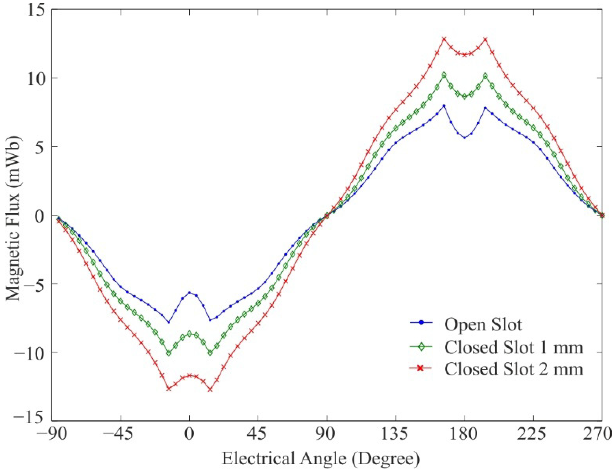
A transient FE-simulation of the magnetic flux through the entire slot and the air-gap is shown for three different stator geometries in
Figure 8. The simulations are done over one pole pair. The magnetic flux reaches its peak when the closed slot is in-between two magnets. The open slot shows the lowest value of leakage flux, and it is increasing with the thickness of the closed slot.
Figure 8.
Magnetic flux leakage through one slot and in the air-gap for: open slot (dot); closed slot 1 mm thick (diamond); and closed slot 2 mm thick (cross), simulated over one magnetic pole pair.
Figure 8.
Magnetic flux leakage through one slot and in the air-gap for: open slot (dot); closed slot 1 mm thick (diamond); and closed slot 2 mm thick (cross), simulated over one magnetic pole pair.
In
Figure 9, three different stator geometries are simulated showing the flux through one closed slot for each case. The simulations are performed over one pole pair with thicknesses of 0.5 mm, 1 mm and 2 mm.
Figure 9.
Magnetic flux through the closed slot at a thickness of 0.5 mm (dot), 1 mm (diamond) and 2 mm (cross), simulated over one magnetic pole pair.
Figure 9.
Magnetic flux through the closed slot at a thickness of 0.5 mm (dot), 1 mm (diamond) and 2 mm (cross), simulated over one magnetic pole pair.
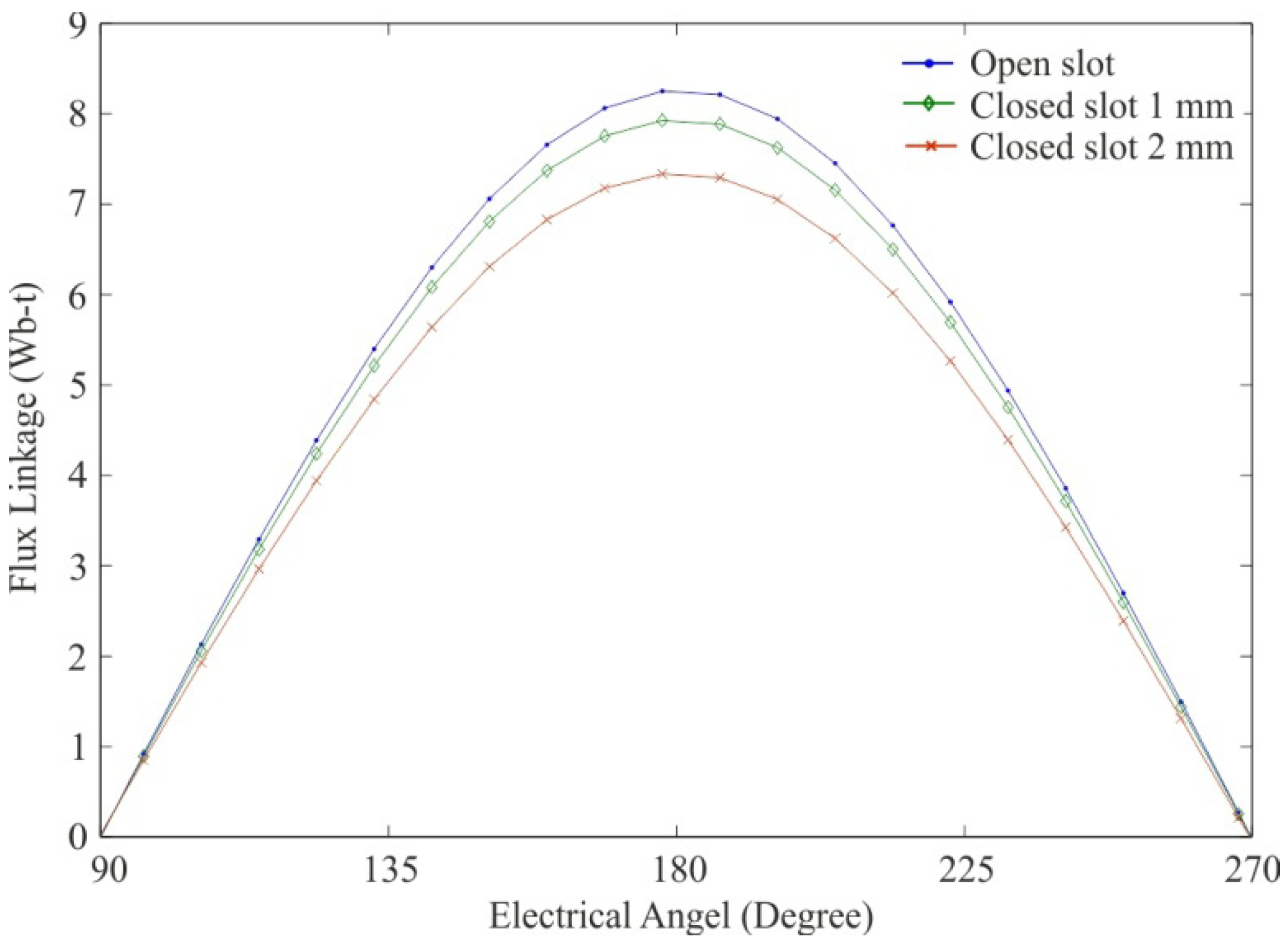
Figure 10, presents the flux linkage of the machine during no-load for three different thickness of the stator slots.
Figure 10.
Flux linkage for one phase of the machine during 180 electrical degrees for: open slot (dot); closed slot 1 mm thick (diamond); and closed slot 2 mm thick (cross).
Figure 10.
Flux linkage for one phase of the machine during 180 electrical degrees for: open slot (dot); closed slot 1 mm thick (diamond); and closed slot 2 mm thick (cross).
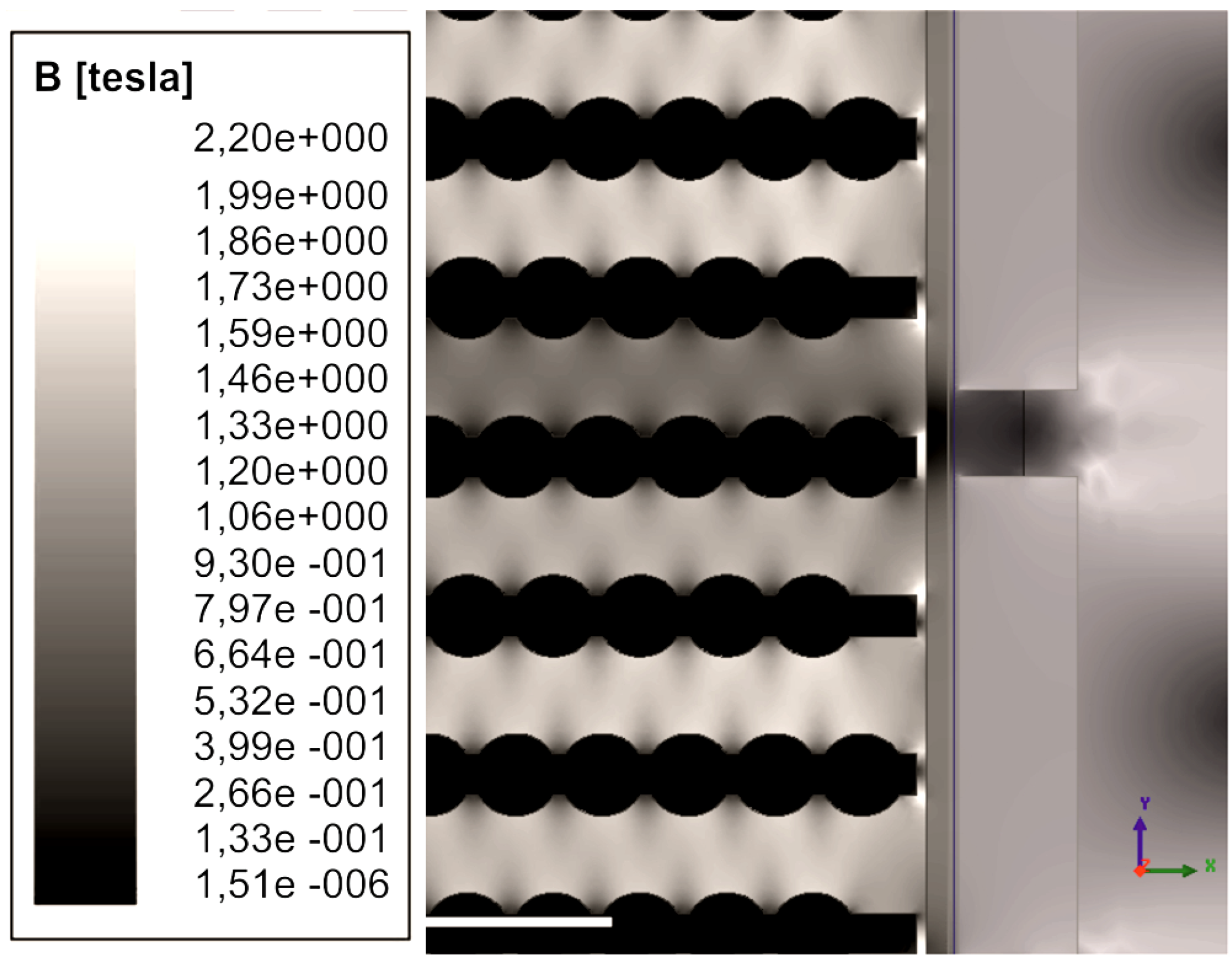
The induced magnetic flux density for a specific position of the stator for closed slots with 1 mm is shown in
Figure 11. Bright areas indicate higher values and dark areas indicate lower values of the magnetic flux density. The magnetic flux density reaches its peak in between two magnets as indicated in
Figure 8 and
Figure 9.
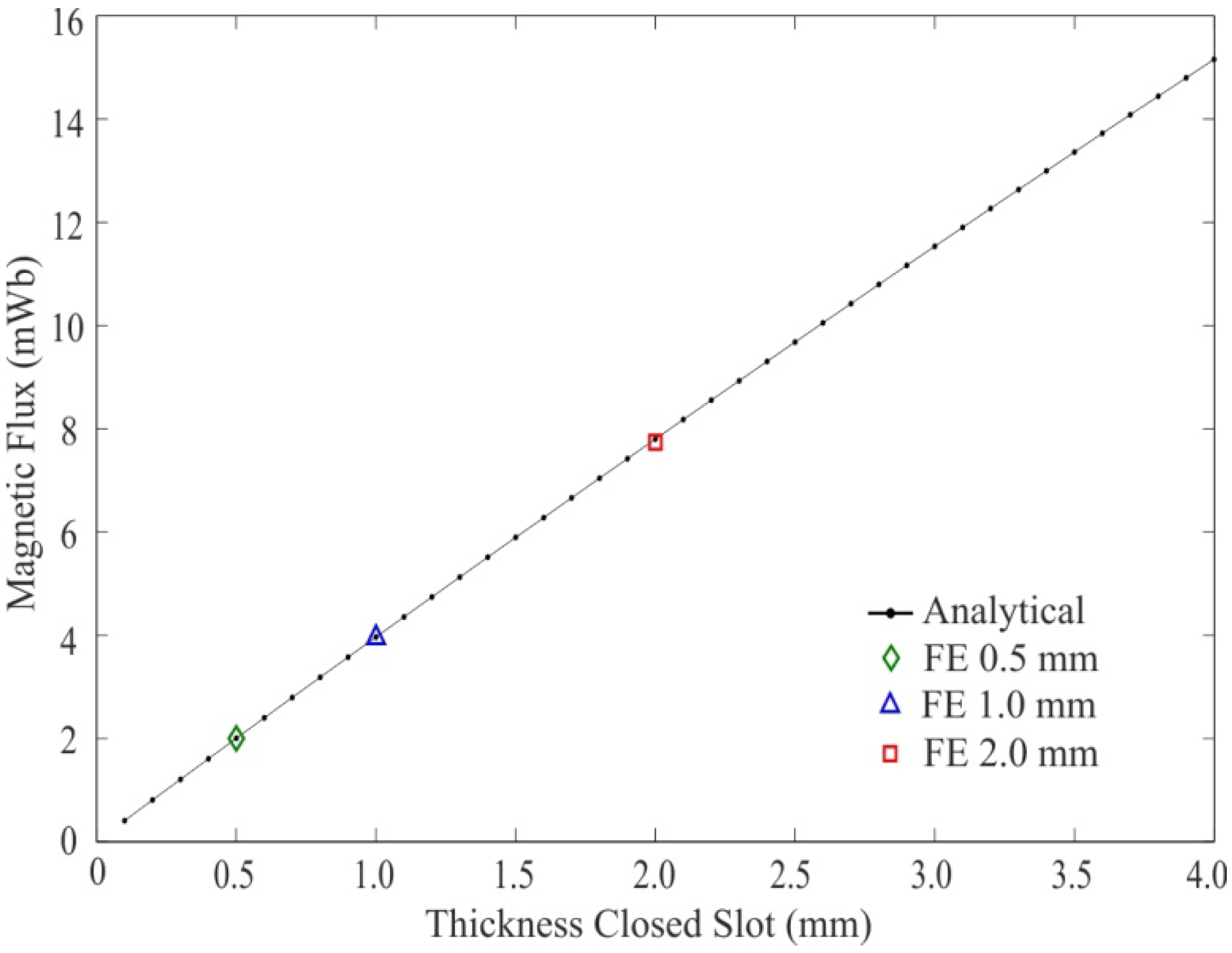
The analytically derived model for the peak value of the flux through one closed slot is plotted with black dots in
Figure 12. The thickness of the closed slot from 0.1 mm to 4.0 mm is shown on the x-axis. The leakage flux in miliWeber through the slot is shown on the y-axis. The maximum values received from the FE-simulation are also inserted in the plot for three different thicknesses, 0.5 mm, 1 mm and 2 mm.
Figure 11.
Induced magnetic flux density in stator, air-gap and back steel for 1 mm thickness of the closed slots.
Figure 11.
Induced magnetic flux density in stator, air-gap and back steel for 1 mm thickness of the closed slots.
Figure 12.
Peak magnetic flux through one closed slot for: 0.5 mm (diamond); 1 mm (triangle); and 2 mm (square) with FE-analysis compared with analytical results from 0.1 mm to 4 mm in dots.
Figure 12.
Peak magnetic flux through one closed slot for: 0.5 mm (diamond); 1 mm (triangle); and 2 mm (square) with FE-analysis compared with analytical results from 0.1 mm to 4 mm in dots.
5. Discussion
The results indicate that closed slots afford some benefit regarding the magnetic flux density in the air-gap and the cogging force, compared to the open slots design. However, the advantages need to be superior to that of the increased flux leakage through the closed slots and the decrease of flux linkage. By closing the slot, the magnetic flux entering the stator slightly increases with the thickness of the slot, see
Figure 7. Comparing open slot and closed slot with 2 mm thickness, the peak value of the flux entering the stator is increased by about 2.4%.
The results presented in
Figure 5 clearly show that the slot harmonics in the magnetic flux density are reduced when using closed slots. Some harmonic content is still present because of the low relative permeability of the closed slots. The difference between 1 mm and 2 mm are distinguished because we have higher saturation and lower permeability at 1 mm than 2 mm. The flux density peaks in the open slots case, have higher flux density than the closed slots due to fringing. In
Figure 6, the cogging force is plotted on ignoring the longitudinal end effects which occur when a magnet slips in and out of the stator. From
Figure 6, it is clear that the peak cogging force is reduced with increasing thickness of the closed slot.
Looking at
Figure 9, one can see that the peak of the leakage flux occurs when one closed slot is positioned in between the two magnets. All magnetic flux shown in
Figure 8 and
Figure 9 does not contribute to the leakage flux; at different positions some of the flux uses the closed slots to link around the winding. Comparing
Figure 8 and
Figure 9, the leakage flux through the closed slot contributes about 40% of the total leakage flux through the slot. By increasing the thickness of the closed slots, the harmonics in the flux density are reduced, but the leakage flux is increased. An optimization process between these two is needed to find the optimal size of the closed slots.
The flux linkage presented in
Figure 10 decreases with the increased thickness of the closed slot. The rise in magnetic flux entering the stator for closed slots does not contribute to the flux linkage of the machine which would have an impact on the induced voltage of the machine. One way to keep the same flux linkage in the machine for the open and closed slots cases could be to change the size of the permanent magnets.
In
Figure 11, the magnetic flux density is plotted. Looking at the bright areas, the flux density is high when the closed slots are positioned in between two magnets. The flux density also has peak values at the corners when it is positioned in the middle of the magnet. This is due to the flux being forced through the corner. Due to the limited value of the magnetic potential difference from the permanent magnets, the relative permeability will converge to a value above the value of air. In this magnetic circuit it will converge to a value of about 16.
The magnetic flux
versus closed slot thickness shown in
Figure 12 appears to be linear. This is due to the magnetic potential and the reluctance decrease caused by the thickness of the closed slot, where the reluctance decreases approximately with the square of the magnetic potential difference.
The maximum difference between the simulated results and the analytical model is below 1%, which indicates a good agreement between the two models.
The cogging force is related to the magnetic flux density in the air-gap. By reducing the slot harmonics in the flux density, the cogging force could also be reduced [
14]. Earlier designs to reduce the cogging force in the generator developed by Uppsala University used fractional winding, by breaking the symmetry of the magnet attracting to the stator teeth [
15]. The fractional winding technique and slot shape optimization on linear permanent magnet machines has also been investigated in [
16]. This winding results in a lower flux linkage, hence a lower phase voltage from the generator. For closed slots there are no teeth but there will still be a change in the reluctance. Moreover, there will be leakage flux through the closed slots. Further studies of the forces that influence the generator would be of high interest.
The transient FE-simulations are very time consuming but by expanding the analytical model it could become more efficient. Further, by studying the forces, the vibrations in the generator could be analyzed, which are crucial for designing the air-gap width and the design of the seal in order to keep the generator sealed. Another possibility in an expanded model would be to study how the generator behaves during different load cases and how the saturation of the closed slot affects the inductance of the generator.


