Design Analysis of a Novel Synchronous Generator for Wind Power Generation

Abstract
:
1. Introduction
2. Principle of Half-Wave Rectified Excitation
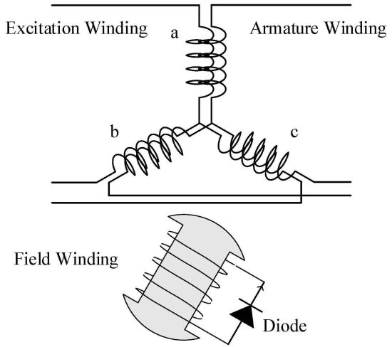
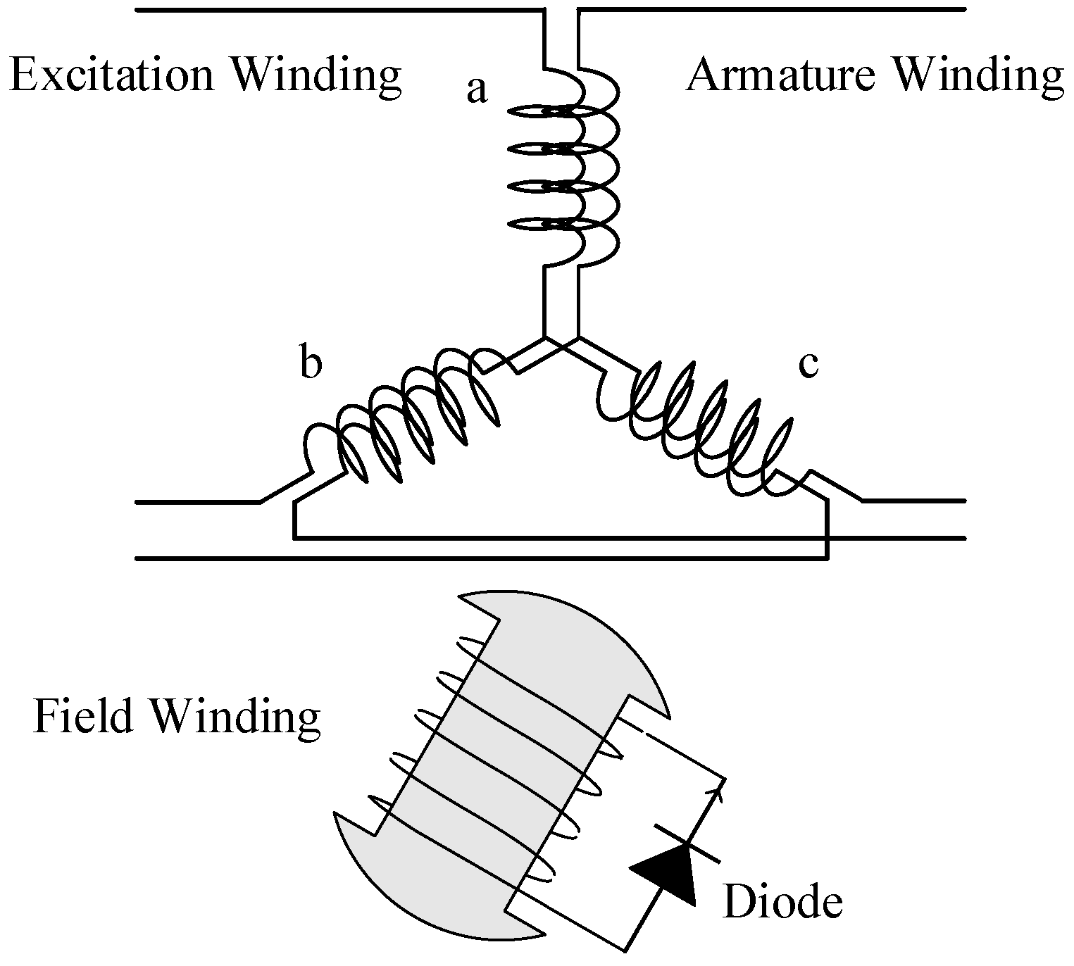
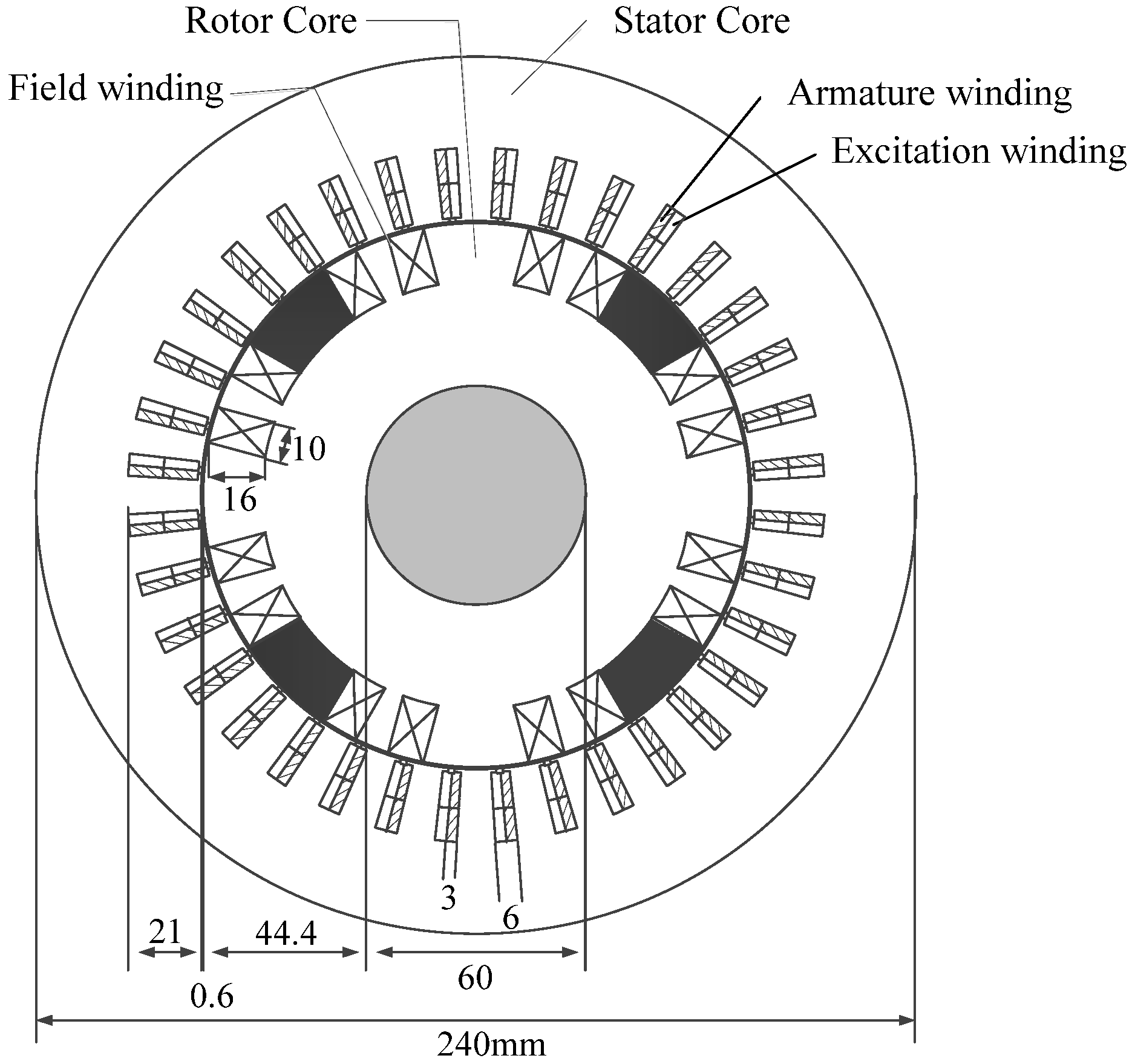
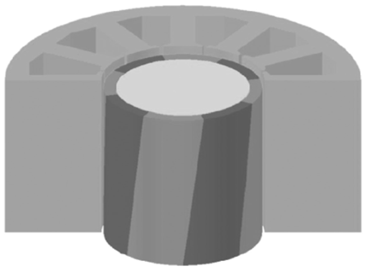
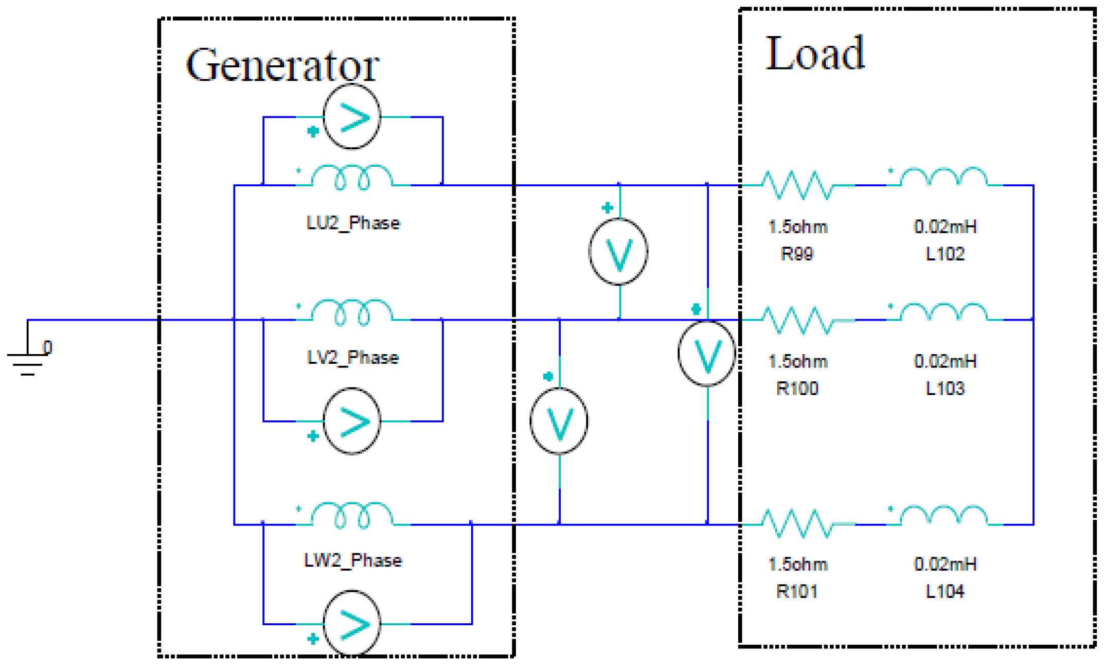
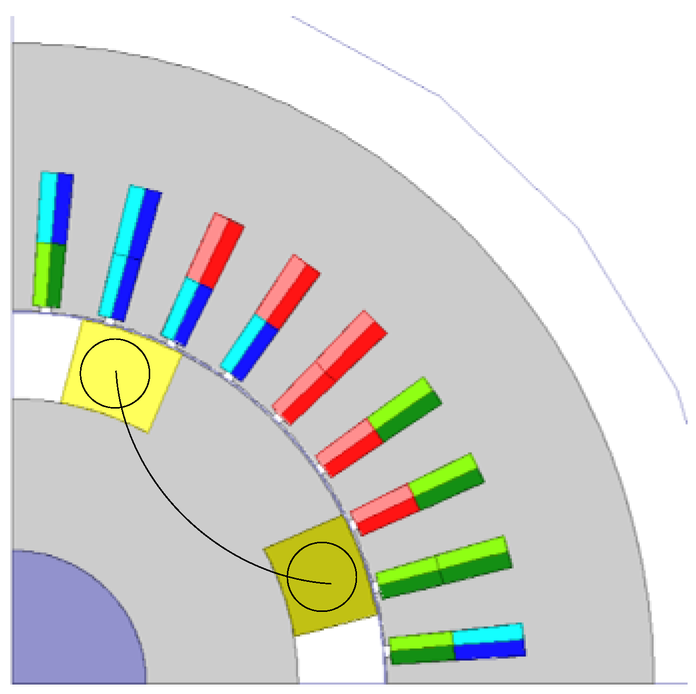
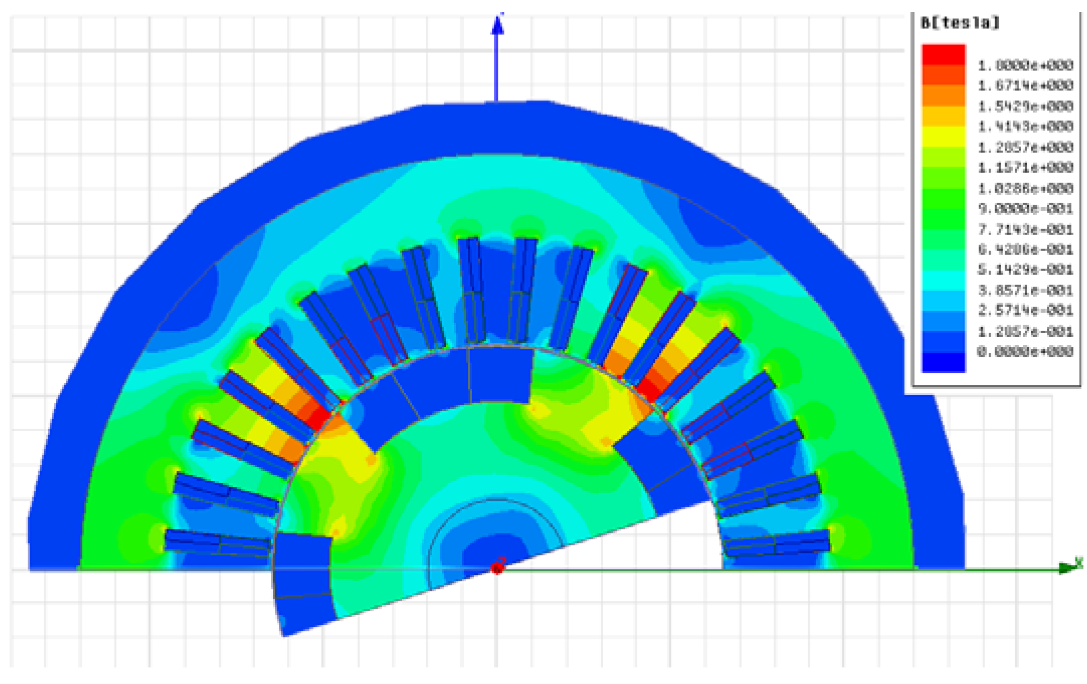
2.1. Generator Model

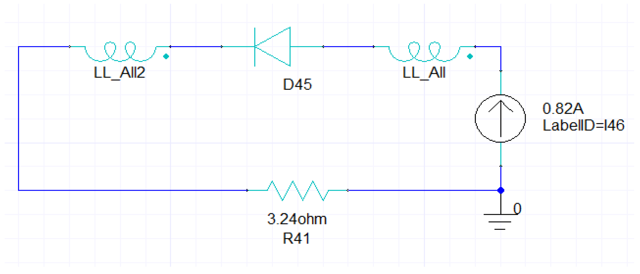
2.2. Voltage Equation
eeq = reieq + dλeq / dt + ωλed
efd = rfdifd + dλfd / dt

λeq = Leqieq
λfd = Mfdied + Lfdifd
2.3. Principle of Brushless Excitation
ieb = Af (t) sin (θ − 2π / 3)
iec = Af (t) sin (θ − 4π / 3)


3. Fundamental Performances of a Half-Wave Rectified Brushless Synchronous Generator

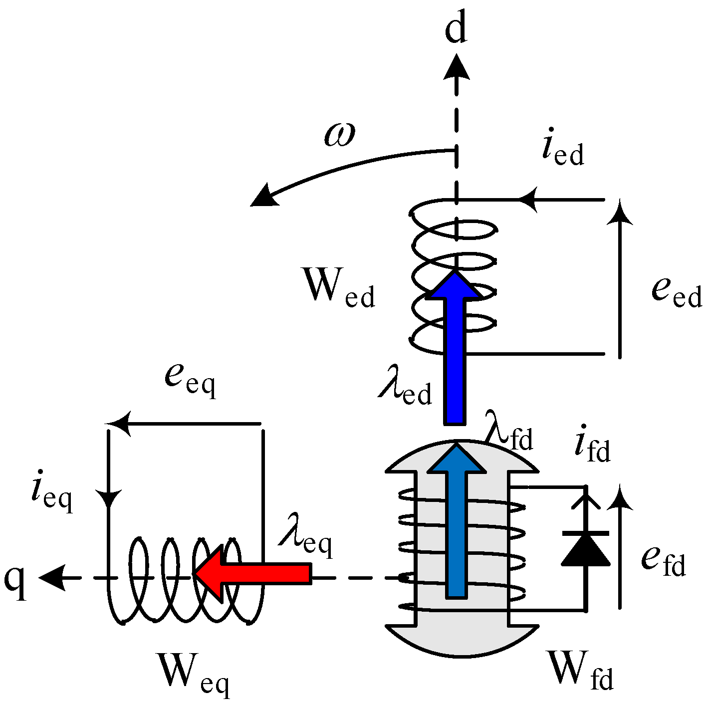
3.1. Under DC Excitation


3.2. Under Half-Wave Rectified Excitation
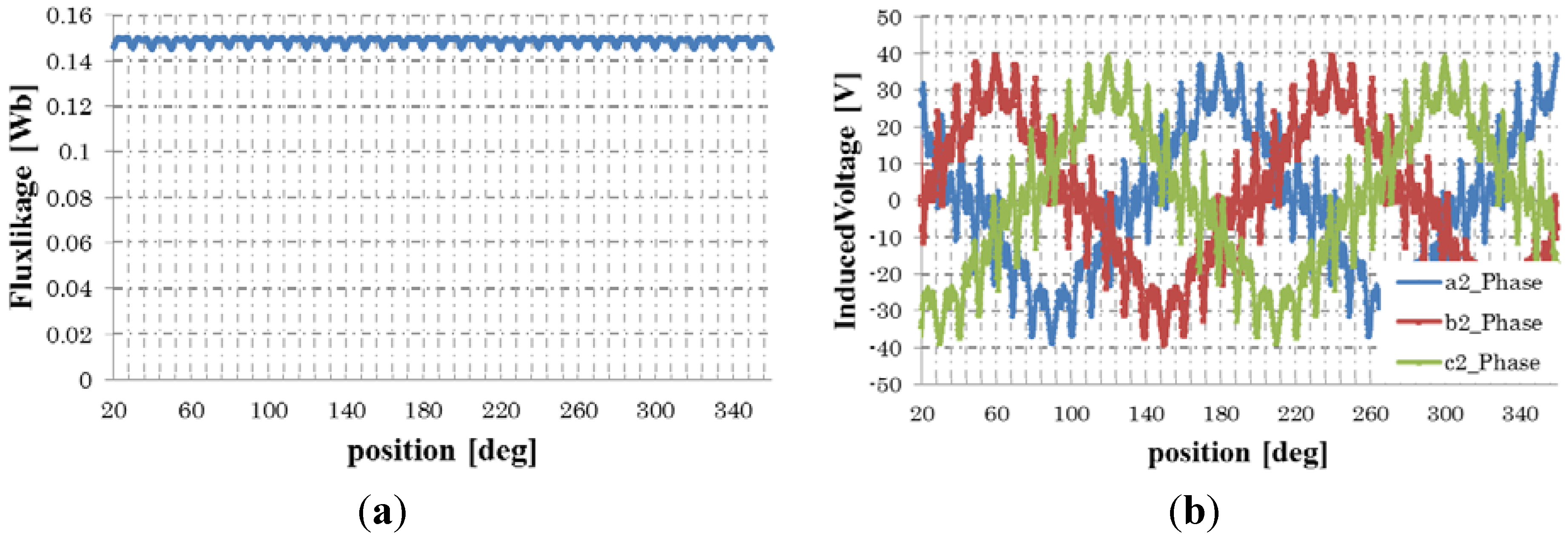
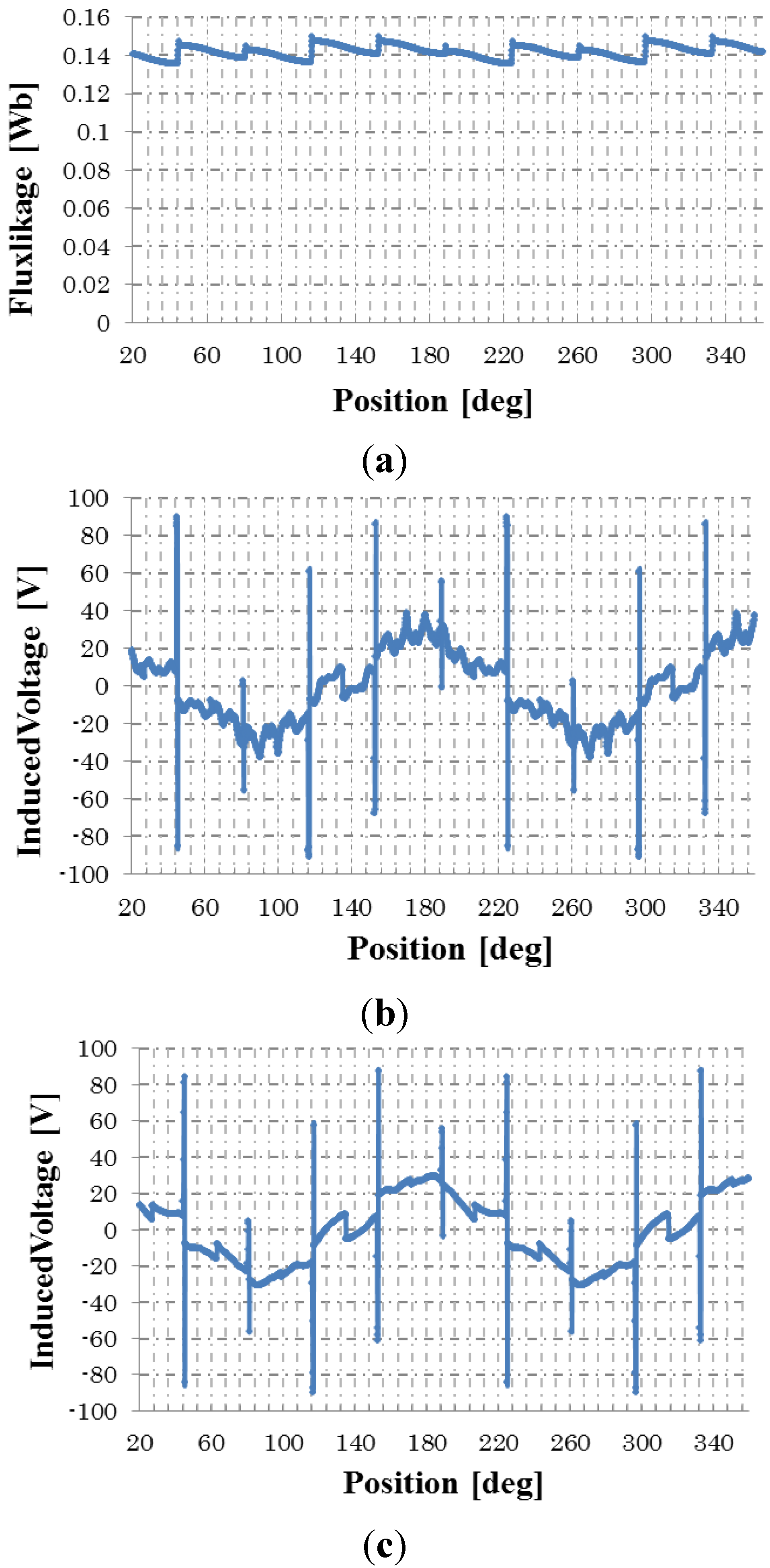
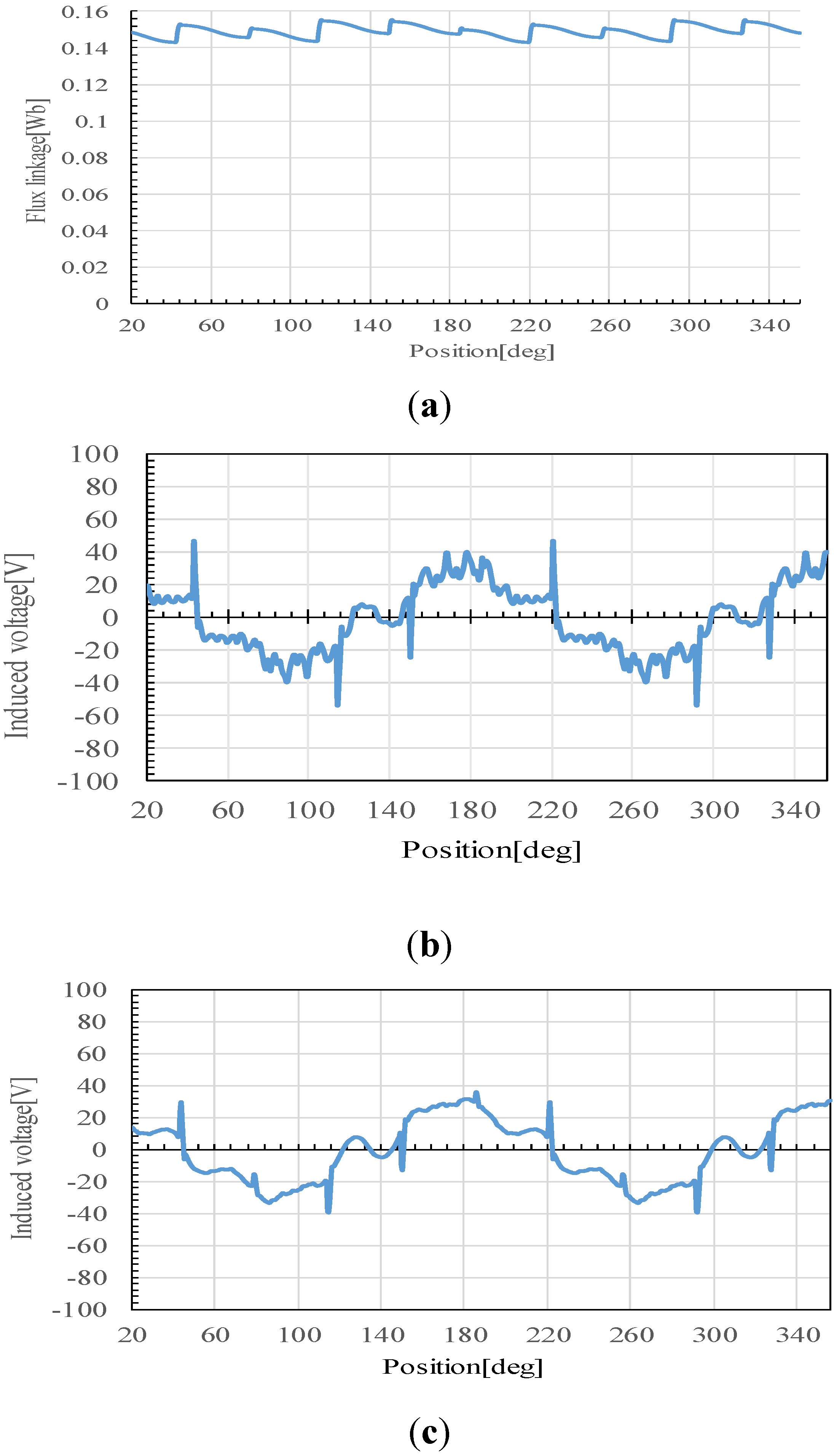
3.2.1. No-Load Condition


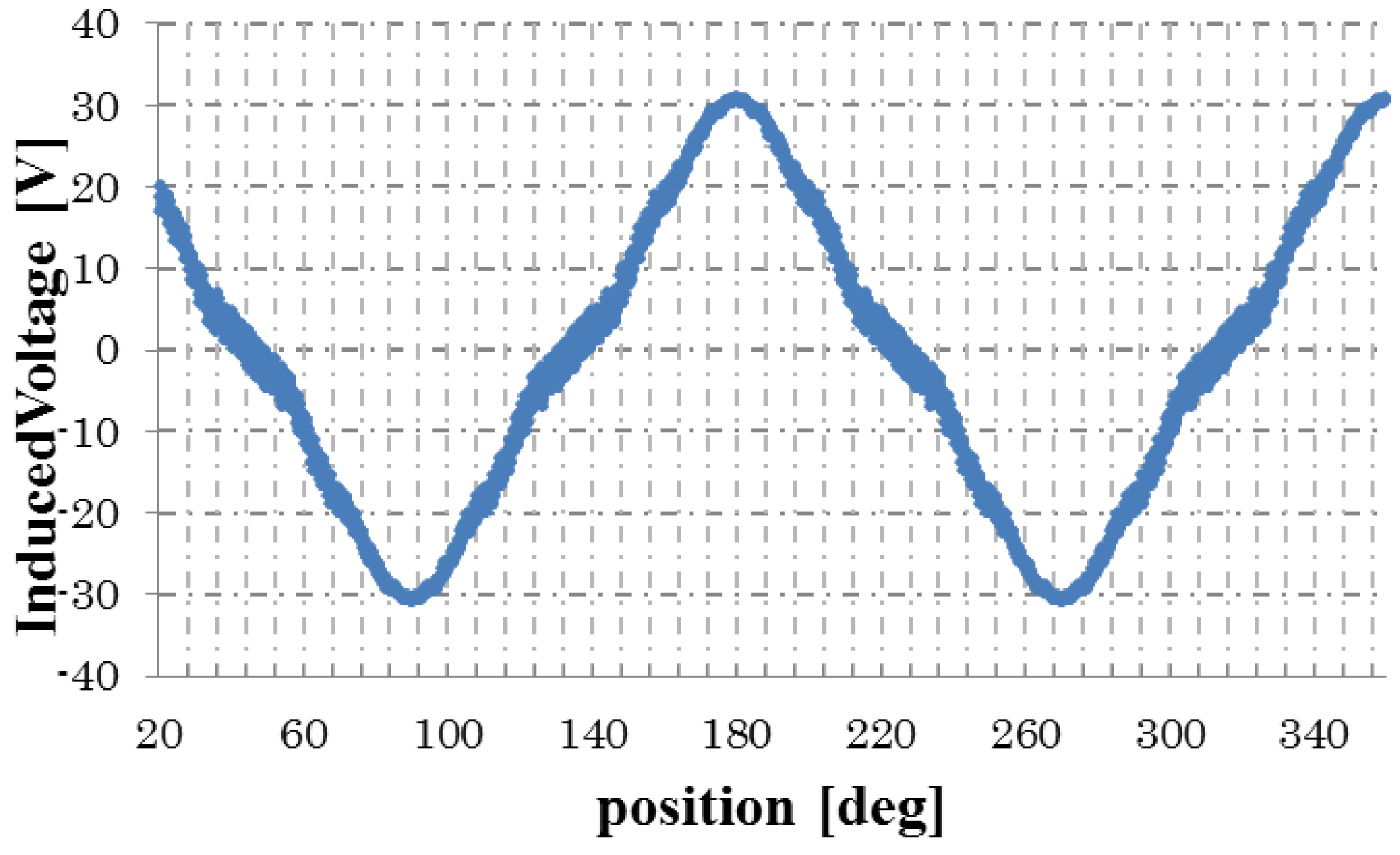
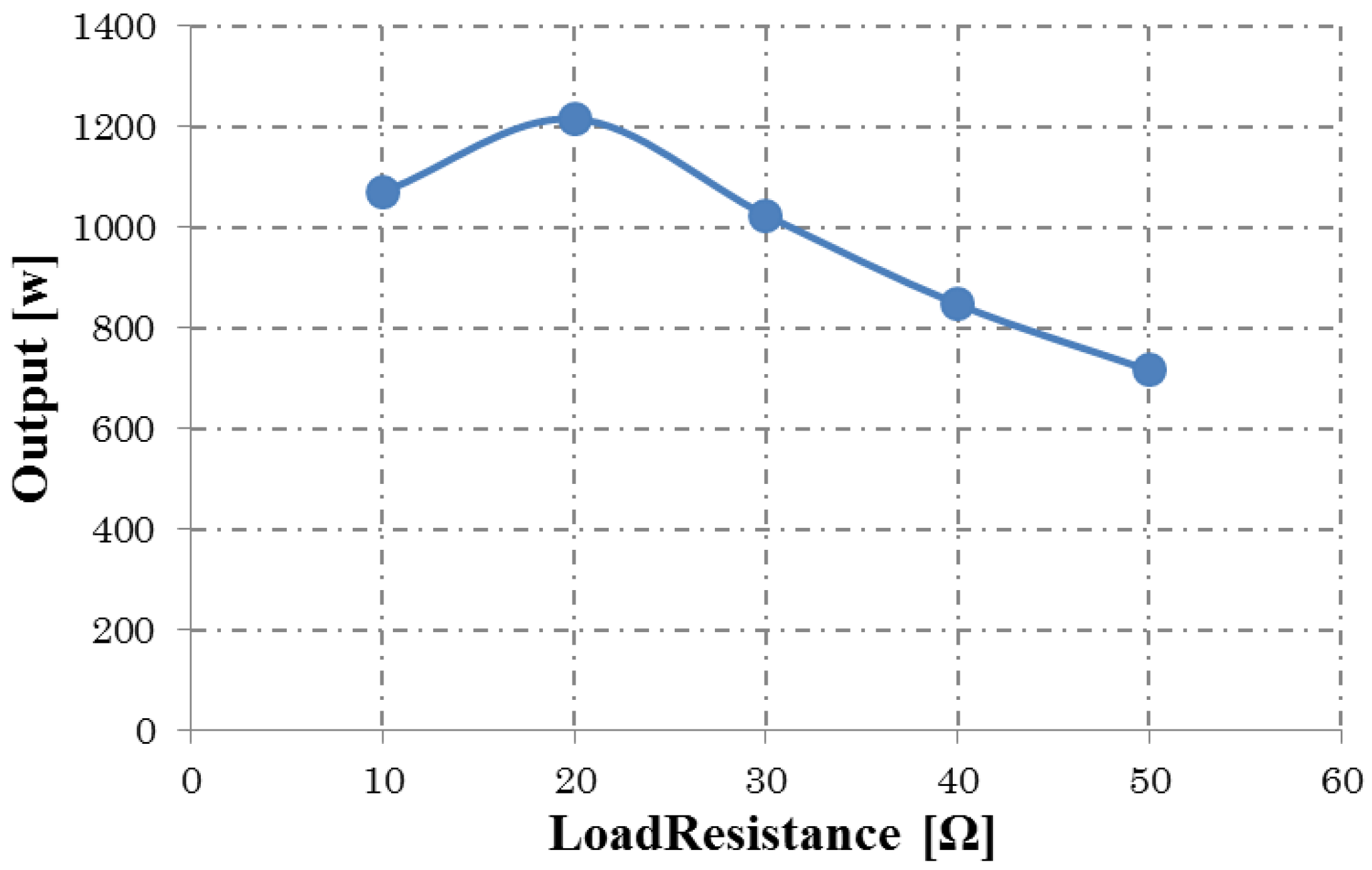
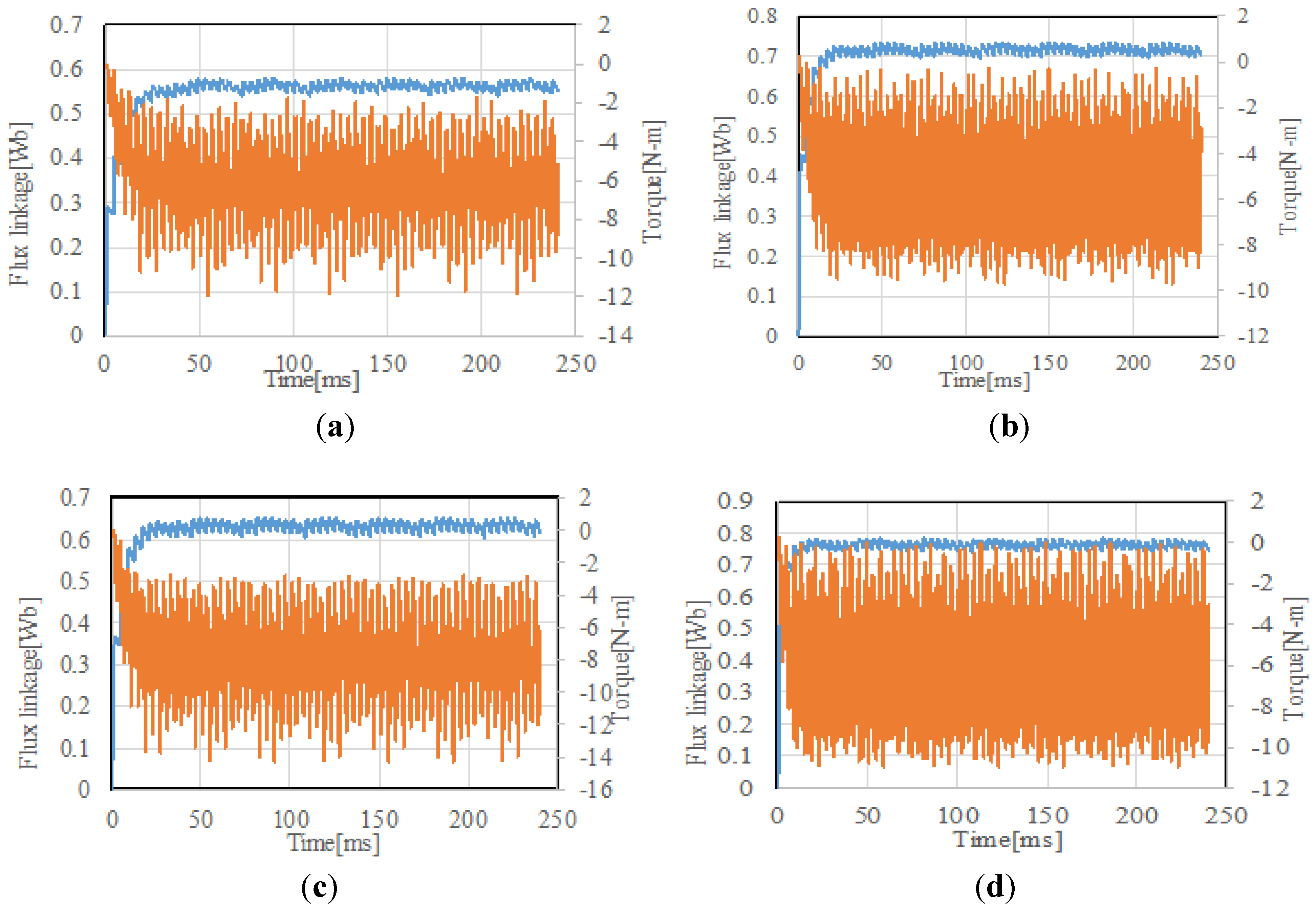
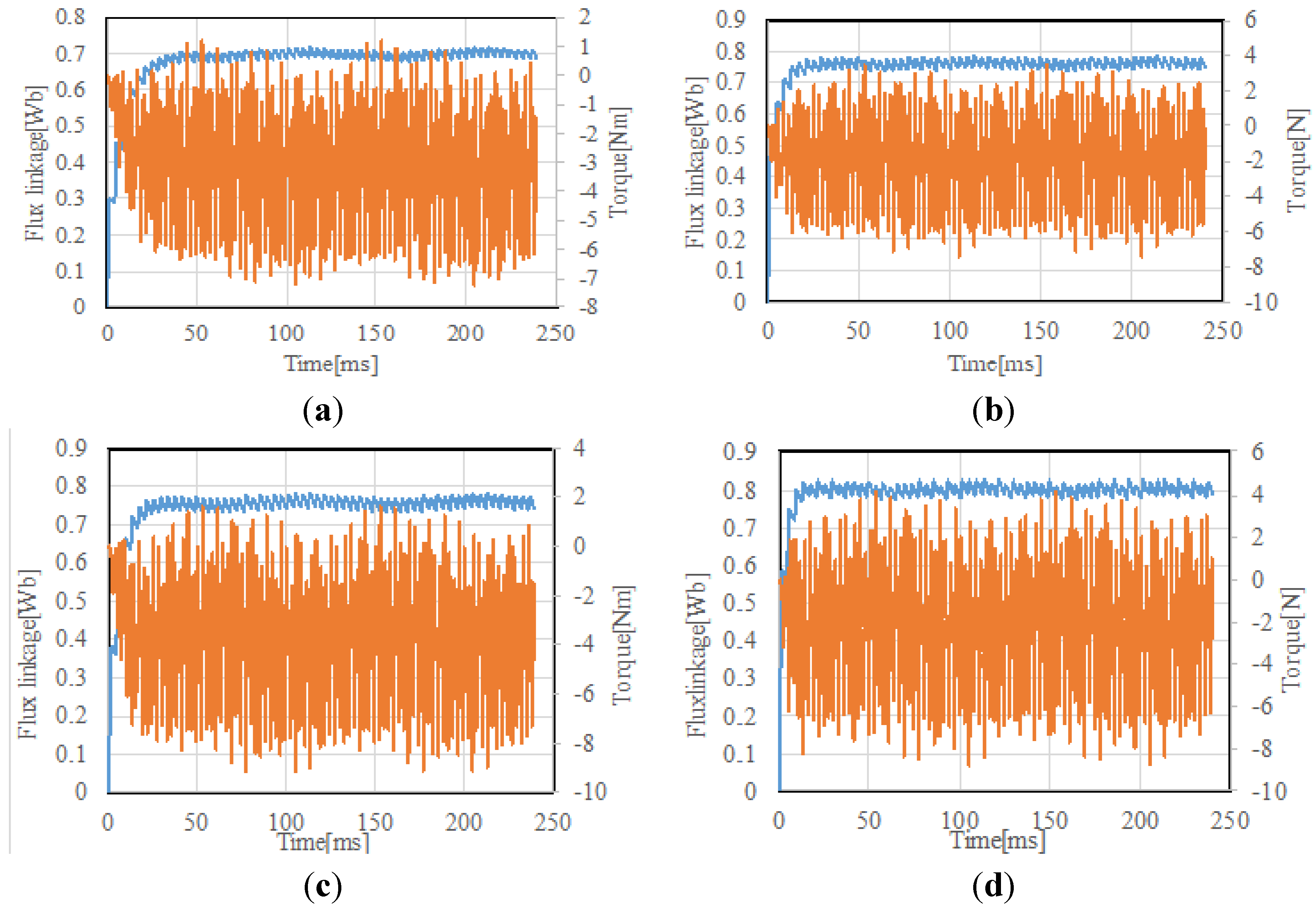
3.2.2. Load Condition


| Load Resistance (Ω) | Induced Voltage (Vrms) | Load Current (Arms) | Output Power (W) | Iron Loss (W) | Copper Loss (W) | Efficiency (%) |
|---|---|---|---|---|---|---|
| 10 | 70.1 | 6.4 | 1069.9 | 77.8 | 126.4 | 86.6 |
| 20 | 103.0 | 4.9 | 1215.5 | 122.3 | 121.5 | 86.9 |
| 30 | 114.9 | 3.7 | 1024.2 | 125.3 | 119.2 | 84.9 |
| 40 | 120.3 | 2.9 | 847.2 | 132.7 | 119.1 | 82.1 |
| 50 | 123.4 | 2.4 | 715.7 | 137.3 | 120.3 | 79.1 |
| Load Resistance (Ω) | Induced Voltage (Vrms) | Load Current (Arms) | Output Power (W) | Iron Loss (W) | Copper Loss (W) | Efficiency (%) |
|---|---|---|---|---|---|---|
| 10 | 79.9 | 7.0 | 1348.8 | 87.4 | 168.3 | 86.4 |
| 20 | 111.7 | 5.3 | 1432.1 | 127.8 | 164.6 | 86.2 |
| 30 | 121.7 | 3.9 | 1149.3 | 137.8 | 161.3 | 83.3 |
| 40 | 126.0 | 3.1 | 930.6 | 143.7 | 161.7 | 79.5 |
| 50 | 127.8 | 2.5 | 768.3 | 144.5 | 160.1 | 76.8 |


4. Design Analysis for Improving Performance
4.1. Rotor Diameter
| Design Model (Rotor Radius (mm)) | Induced Voltage (V) | Output Power (W) | Efficiency (%) |
|---|---|---|---|
| Design 1 (74.4) | 103.01 | 1215 | 86.9 |
| Design 2 (69.4) | 116.01 | 1530 | 87.4 |
| Design 3 (64.4) | 115.14 | 1471 | 82.2 |
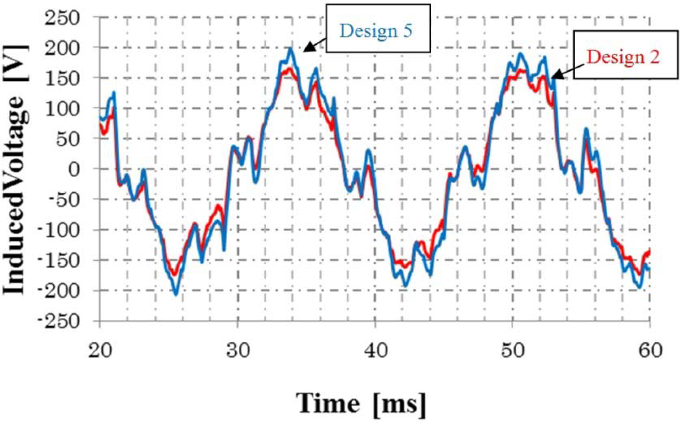
4.2. Rotor Configuration

| Design Model (Rotor Radius (mm)) | Induced Voltage (V) | Output Power (W) | Efficiency (%) |
|---|---|---|---|
| Design 4 (74.4) | 115.10 | 1,523 | 88.1 |
| Design 5 (69.4) | 134.26 | 2,064 | 89.7 |
| Design 6 (64.4) | 138.17 | 2,156 | 87.4 |

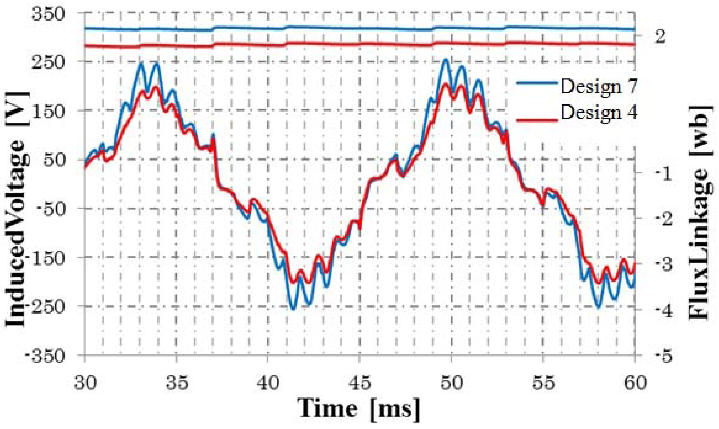
4.3. Air Gap Length


| Design model (Rotor Radius (mm)) | Induced Voltage (V) | Output Power (W) | Efficiency (%) |
|---|---|---|---|
| Design 7 (74.4) | 139.11 | 2285 | 90.7 |
| Design 8 (69.4) | 149.33 | 2640 | 91.7 |
| Design 9 (64.4) | 149.67 | 2646 | 91.9 |
5. Speed Characteristics

6. Conclusions
Conflicts of Interest
References
- Oyama, J.; Toba, S.; Higuchi, T.; Yamada, E. The characteristics of half-wave rectified brushless synchronous motor. In Proceedings of the Beijing International Conference on Electrical Machines, Beijing, China, 10–14 August 1987; pp. 654–657.
- Oyama, J.; Toba, S.; Higuchi, T.; Yamada, E. The principle and fundamental characteristics of half-wave rectified brushless synchronous motor. Electr. Eng. Jpn. 1987, 107, 98–106. [Google Scholar]
- Nonaka, S.; Kesamaru, K. Brushless self-excited type single-phase synchronous generator using wound-rotor type three-phase induction machine. Trans. IEEE Jpn 1981, 101, 743–750. [Google Scholar]
- Sakimura, K.; Higuchi, T.; Yuichi, Y.; Abe, T. Principle and characteristic analysis of a half-wave rectified brushless synchronous generator. In Proceedings of the International Conference on Electrical Machines and Systems, Busan, Korea, 26–29 October 2013; pp. 708–711.
© 2014 by the authors; licensee MDPI, Basel, Switzerland. This article is an open access article distributed under the terms and conditions of the Creative Commons Attribution license (http://creativecommons.org/licenses/by/3.0/).
Share and Cite
Higuchi, T.; Yokoi, Y.; Abe, T.; Sakimura, K. Design Analysis of a Novel Synchronous Generator for Wind Power Generation. Machines 2014, 2, 202-218. https://doi.org/10.3390/machines2030202
Higuchi T, Yokoi Y, Abe T, Sakimura K. Design Analysis of a Novel Synchronous Generator for Wind Power Generation. Machines. 2014; 2(3):202-218. https://doi.org/10.3390/machines2030202
Chicago/Turabian StyleHiguchi, Tsuyoshi, Yuichi Yokoi, Takashi Abe, and Kazuki Sakimura. 2014. "Design Analysis of a Novel Synchronous Generator for Wind Power Generation" Machines 2, no. 3: 202-218. https://doi.org/10.3390/machines2030202