1. Introduction
The application of industrial robots in automated welding processes is well established with increasing numbers of robot sales worldwide year by year [
1]. To remain competitive in this growing market and to meet customer demands, all robot manufacturers invest a lot of efforts to improve the performance of their products. This will be achieved, in particular, through technical innovation, an increase of functionality, and better reliability.
In this context, for a number of years novel automation concepts have entered the focus of interest. They are based on production cells with multiple industrial robots and advanced control concepts that allow robots to share a common work space and to execute manufacturing processes through collaboration.
The reasons of applying teams of collaborating robots in manufacturing are manifold. Benefits are especially obvious in the case of complex welding jobs that are difficult, inefficient, or uneconomic to be completed by only one single robot. Therefore, if applicable, robot teamwork can contribute to increase profitability, efficiency, and cost-effectiveness in production automation [
2].
Currently, most of the “multi-robot” stations being installed or offered on the market are built from robots of the same type or of a product family. This is because of the individual concepts developed by the robot manufactures to assure controlled interaction and collaborative activities. Very common are master-slave concepts to support the complex and time-consuming programming procedures through specially-tailored proprietary software functions. Notable examples in this context are for instance the MultiMove function of ABB, the Independent/Coordinated function of Motoman Yaskawa, or the RoboTeam function launched by KUKA [
3,
4,
5]. In parallel to the product development of robot manufacturers, extensive scientific-driven research has also given birth to numerous novel technologies in robotics through the last decades. This has led to considerable functional improvement, increased applicability, and better performance of the robot systems. In this context the multi-robot technology has also been subject of research and technological development. Meanwhile, many valuable results, dependent on specific settings and applications, are available. They provide a useful platform of technologies and software tools for further robotic development, and especially for multi-robot applications [
6,
7]. In particular, open source products with free access to already-existing technological achievements, for instance in the fields of motion planning, collision avoidance, environmental perception, localization, searching, and mapping, are increasingly applied by developers in deploying new system designs and advanced robotic technology [
8,
9].
However, it must be recognized that most of the results gained from research in this sector have been dedicated to applications of mobile systems or teams of mobile robots being involved in coordinated actions at different degrees of system autonomy. Well known in this context are the results of research initiatives in the field of RoboCup Soccer and RoboCup Rescue, where a continuously-growing community of scientists and researchers has created a wide platform for research, technological development, competition, and exchange of multiple technical and technological solutions [
10,
11,
12].
Less considered, compared to the worldwide research initiatives in the field of mobile robots, is the development of advanced technologies and autonomy for multi-robot applications in industrial production environments. This is especially true in the field of arc welding automation. The reason for this are the technical and technological complexities because, here, coordination and cooperation are concerned not only with how to control the movement of the robots inside the team, but also how to distribute the workload between the robots in a way which assures maximum economic efficiency and team performance and how to cope with conditions and restrictions caused by the welding process itself. Motoman Yaskawa pioneered multi-robot technology for arc welding applications in 1994 and became a market leader in this sector. However, the applicability of their technology is restricted and allows the design and setup of collaborating multi-robot stations only with Motoman products (robots and controllers) and only for certain applications in welding automation [
13]. Despite of this progress, collaborative welding automation with multi robot technology remains complex and many technical problems and issues are still unsolved.
One of these issues, for instance, is related to the question of how to proceed if collaboration within a team of heterogeneous industrial robots with totally different control devices shall be implemented to reach certain economical goals in production. In this case the technical realization mostly fails because of the extensive efforts necessary for programming, lacking interoperability, and insufficient control and interaction concepts.
Therefore, in view of this situation, the research project presented in this paper has been initiated to investigate the problems of multi-robot applications in more detail and to propose basic technical solutions which shall contribute to overcoming still-existing problems and to assure more flexibility in applying multi-robot technology in production environments with arc welding automation by means of advanced control concepts and integration of a certain degree of autonomy into existing systems. To enter any research related to this topic, a couple of aspects and questions of particular relevance have to be addressed first in order to provide a certain baseline for the project work:
How does one generate a neutral job description that will specify the activities to be executed by the robots?
How does one apply the job description for action planning and self–organization of the robot team work?
How does one implement autonomy in terms of path planning and self-coordination?
How does one assure collision-free motion of the robots inside a common work space?
How does one create and design an appropriate communication, interaction, and control infrastructure?
2. XML-Based Job Description
Fundamental to any planning action and controlled interaction for multi-robot systems is a detailed description of the production job to be executed by the robots. Typically, the specification of robot activities is part of the operator’s work during explicit programming of each individual robot and synchronizing their interaction to avoid any collisions.
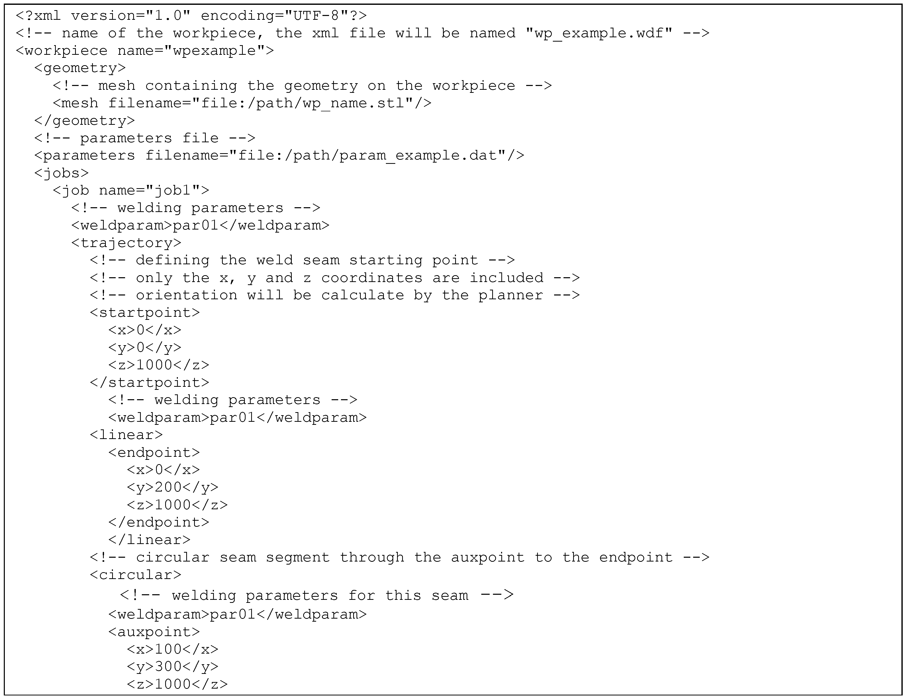
To replace the so called “teach-in” programming which is, as already said, complex and often very time consuming, scripted solutions, such as Petri Nets, icon-based programming, or other scripts have been favored. Within the project an XML-based job description was proposed. It is both human and machine readable, can be applied platform-independently, and is able to provide all information and path data to assure proper planning and coordination of robot activities by computers. For robotized welding this job description has to consider not only geometrical, but also technological, data. Both need to be complemented by instructions to also control peripheral devices, if needed. The geometrical data of the job description typically represent the spatial positions of the weld lines, end-effector orientations during welding, and also points in the 3D workspace which need to be used by the robots for safety reasons and home positioning. Additionally, technological data have to specify process conditions, like welding speed, weld gun orientation, stick-out of the wire electrode, or weaving of the torch. Finally, data have to be considered to define the power source and wire feeder conditions, as well as welding position, like horizontal, vertical–up, overhead, vertical down, or welding in gravity-affecting positions. The generation of the job description in the project was performed by means of a specially-designed software tool. It has included an editor, graphical user interfaces, and a set of functions to create XML files interactively by the user. The semantics being applied are related to international standards in welding engineering (EN ISO 15611, 15614).
Figure 1 shows a series of instructions and data taken from a typical XML-based job description that has been created within the project.
In this context, all XML descriptions being applied in the project only address the movement of a tool, for instance a weld gun, to execute a manufacturing job. Instructions or information related to any robot or kinematic structure of robots are not considered. Therefore, XML job descriptions are very flexible in their use and can be adapted to any robot or welding machine if an appropriate post-processor is available.
3. Planning and Self-Organization of Robot Team Work
As mentioned before, the goal of this research was to enable teams of robots to organize, plan, and coordinate their work autonomously without any intervention of the human operator.
To meet this goal, it was decided not to start from the scratch by developing new planning tools, but to use services of the robot operating system (ROS) as an open source framework and to apply ROS functions like MoveIt! for motion planning, inverse kinematic calculations, collision checks, and to control any interaction of the robots, even if they are of a heterogeneous nature [
14].
The first planning activity to implement was a solution to decode the XML job description. For this purpose, a ROS node has been created with use of the library “roscpp” and “TinyXML”. With an integrated parser the node had to extract the position data of the weldlines, as well as the corresponding process parameters, and to load them into an action list. After coordinate transformations of position data from workpiece coordinates into world coordinates of the robot cell, the generated action list served as a database for any further planning activity.
From the practical point of view, any robot activity in welding automation has to consider, in principle, two standard application scenarios of importance for the planning concept envisaged:
Planning of robot actions being executed in a static working environment at a defined spatial position and orientation of the workpiece; or
Planning of robot actions being executed in a continuously changing working environment. This will happen, for instance, in the case of varying workpiece positions and frequent reorientation of the part to be welded by means of an integrated multi-axis workpiece positioner.
3.1. Self-Organization of Robot Collaboration in Static Working Environments
Although any action planning for the robots involved in the team needs to be adapted to the type of application scenario, there is another important aspect to consider. It is related to the economic goals. In this context the distribution of activities inside the team of robots, which has to assure minimal job execution times, is addressed. Thus, motion planning and self-organization also have to cope with an optimization problem in balancing the work load inside the team.
In order to cope with this kind of optimization problem, “self-organization algorithms” have been developed and implemented. They were designed to consider the different application scenarios and to allow the determination and distribution of activities in real-time by following certain optimization criteria. In this project they were related to the rule of “minimum path lengths”.
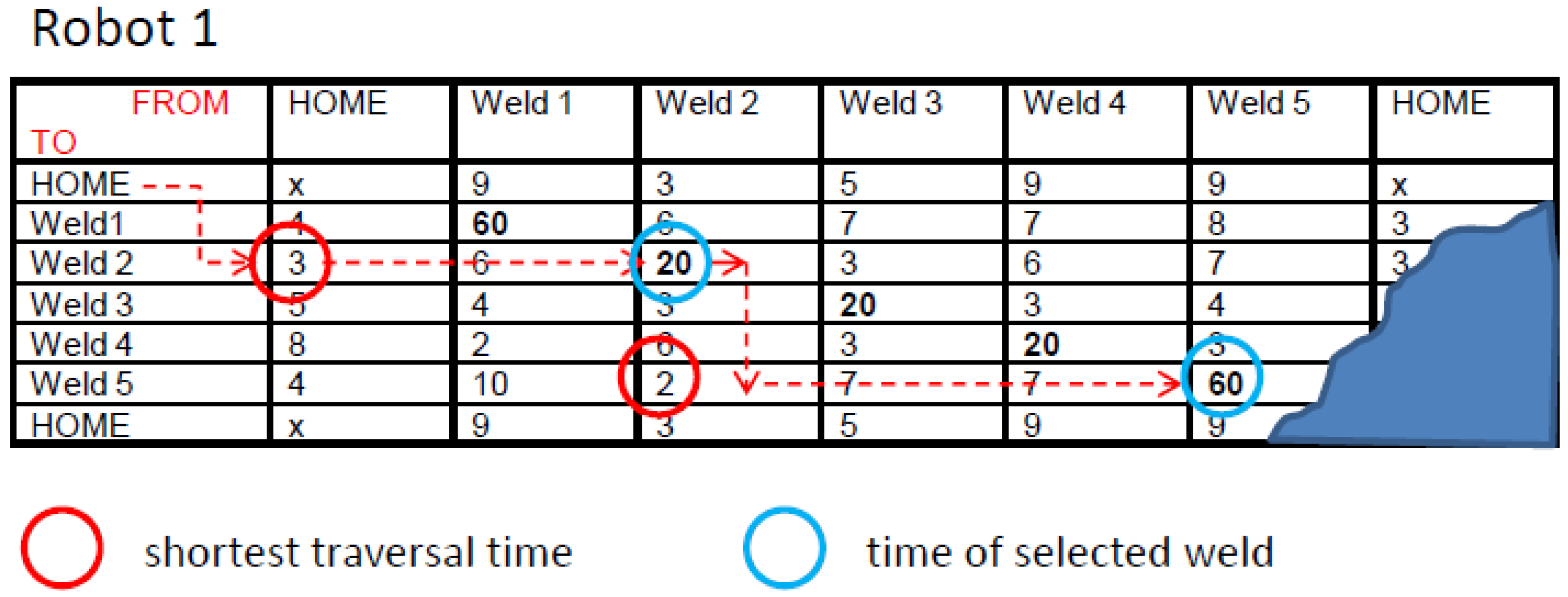
For a static working environment, the algorithms used a set of planning matrices of (n + 2) × (n + 2) elements, one for each robot of the team, where (n) represents the total number of lines to be welded. The extension by two additional matrix elements was necessary to consider robot movements from their home positions at the beginning of any job execution, and the return to the home position after having finalized the last welding job.
Inside the matrix itself, each element Pi,k with i = 1,…, n + 2 (column index) and k = 1,…, n + 2 (line index) contains a time factor in seconds. This factor either indicates the estimated traversal time of the robot (based on Euclidian distances) when moving from its current position to a target position inside the working space. Or, in the case of matrix elements located on the main diagonal, the factors represent the time of welding the joint being addressed through the position and indices of the matrix element. For instance P2,2 indicates the welding time for joint 1, P3,3 for joint 2, etc.
According to the example presented in
Figure 2 the calculation starts at element P
1,1 (home position) and continues searching the nearest target position for the robot to go next. This position is found by evaluation of all time factors in the matrix elements of column index i = 1, respective of the elements P
1,2 up to P
1,n+2. The matrix element found with the lowest time factor determines the line index k which has to be used to identify the position the robot to go next. By setting index i equal k, the corresponding matrix element P
i,k = P
k,k on the main diagonal is addressed. This represents the welding time (20 s) for the joint to be welded next. Similar calculations were related to the matrices dedicated to the other robots of the team. Matrix elements being used already in a calculation cycle have to be neglected in all further planning activities.
After all robots of the team have finalized their first welding operations, the self-organization algorithm continued with a new search operation. The starting point was now that matrix element on the main diagonal which has been found to identify the joint selected for welding. From this matrix position the algorithm again tried to find the next lowest time factor by checking all elements of the column with index i = 2. As soon as the lowest time factor (2 s) has been identified, a new line index k (k = 5) is found. This specifies the matrix element on the main diagonal (P5,5) with the time factor (60 s) related to the next joint selected for welding. In this way all further calculation cycles have to be performed, each with a column-wise search for the lowest time factor, to find the new line index k for the next weld, followed by a line-wise identification of the matrix element Pi,k on the main diagonal with i = k. This had to be performed for the matrices of all robots involved in the team.
During this self-organization procedure the corresponding time factors for each robot have been accumulated cycle by cycle, so that the actual duty time (time to go + time to weld) for each of the robots was always available and could be monitored.
The duty time of the robots was of special importance when approaching the end of the calculation and optimization procedures. Normally the number of residual joints to be welded is either:
- (i)
less than the number of robots in the team; or
- (ii)
equal to the number of robots in the team.
In the case of (i), the self-organization algorithm had to distribute the final welding tasks not only in line with the “shortest path length” criteria. It also had to care for a balanced workload of the robots in the team, in order to assure minimal job execution times. Therefore, priority in welding task distribution has preferably been given to those robots with the shortest accumulated duty times. Any decision “next action agreed” or “next action disagreed” after each calculation cycle was taken by the self-organization algorithms as follows:
[Accumulated duty time of the robot so far + Residual time for the welds still to do]/[Number of robots in the team] = Estimated duty time per robot on average
IF [Estimated duty time per robot in average] > [Actual accumulated duty time of robot] THEN ➔ Decision: Next action agreed
IF [Next action agreed] THEN [Calculation of the individual Duty Rate DRi of the robots]
DRi = [Estimated duty time per robot in average]/[Actual accumulated duty time of robot]; with i = (1,..., m); m = total number of robots in the team
Final distribution of welding tasks to robots with shortest duty time:
FOR I = 1 to Number of residual welds to do next
➔ X = Max {DR1, DR2,..., DRm}
➔ X identifies robot to take over one of the residual welds.
Delete DutyRate DRx = X from { }
NEXT.
3.2. Self-Organization in Dynamically-Changing Working Environments
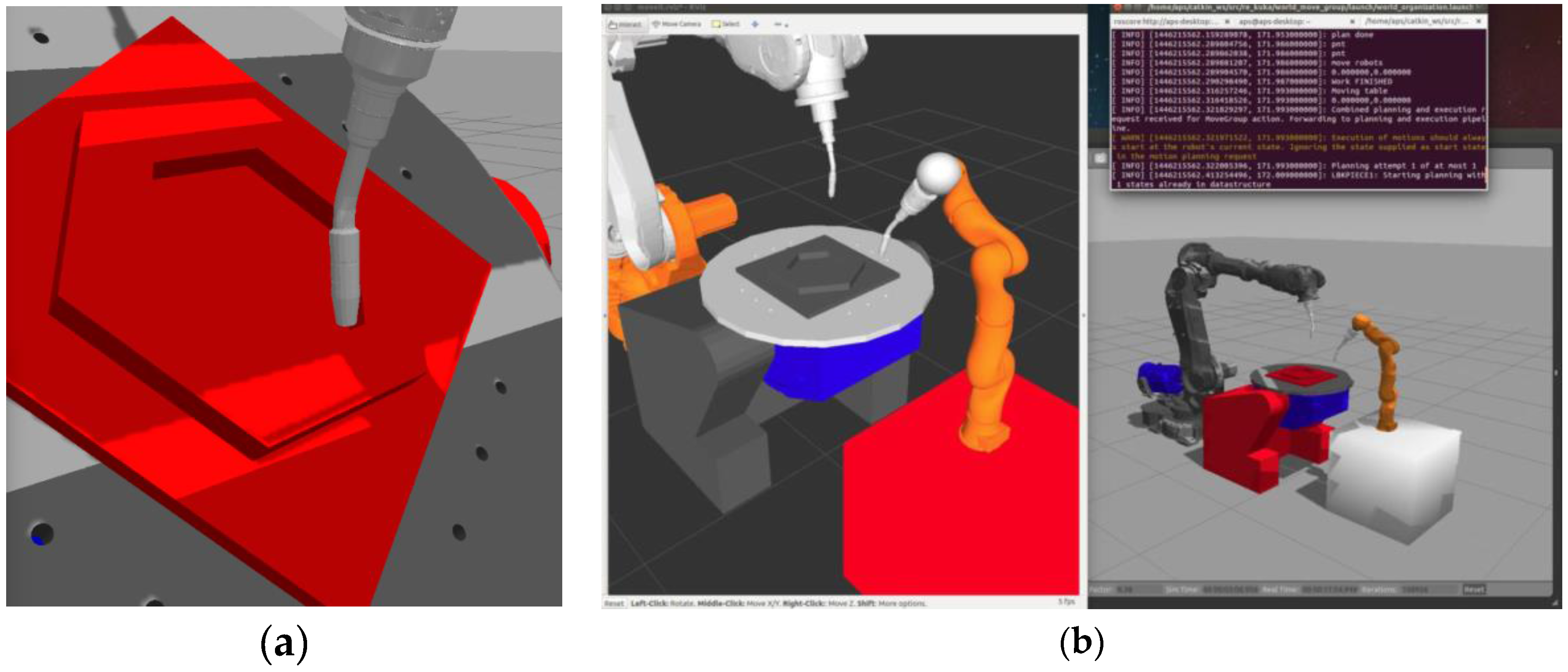
As mentioned above, a second typical application scenario in welding automation represents installations with robots and integrated workpiece positioners to enable a reorientation of the workpieces in accordance to quality demands. Especially, turn and tilt tables are often applied to enable welding in horizontal or so called “gravity” positions (
Figure 3). For high quality welds this position is of essential importance because of the symmetrical heat input into the base material and the optimal weld pool behavior.
To run the self-organization process with respect to dynamically-changing working environments, the ROS–based control system had to start again in extracting the weldline positions and tool orientations from the XML job description. After transformation into the world coordinate system used by ROS and MoveIt!, an action list has, again, been prepared by MoveIt! as the database for self-organization procedures.
The organization of the work load and distribution of activities to the robots involved in the team had to cope again with the “shortest path length rule” to assure minimal job execution times. However, this time, not only the robot movement was of relevance, but also the orientation of the workpiece on the turn and tilt table, and the position of the weldlines inside the configuration space.
To consider these constraints efficiently, all welds to be executed have been split into two classes first. One class typically contained all linear welds and the other one all circular welds. This separation was necessary because of different path planning concepts for the robots when executing linear or circular welds in combination with the external axes of the turn and tilt table.
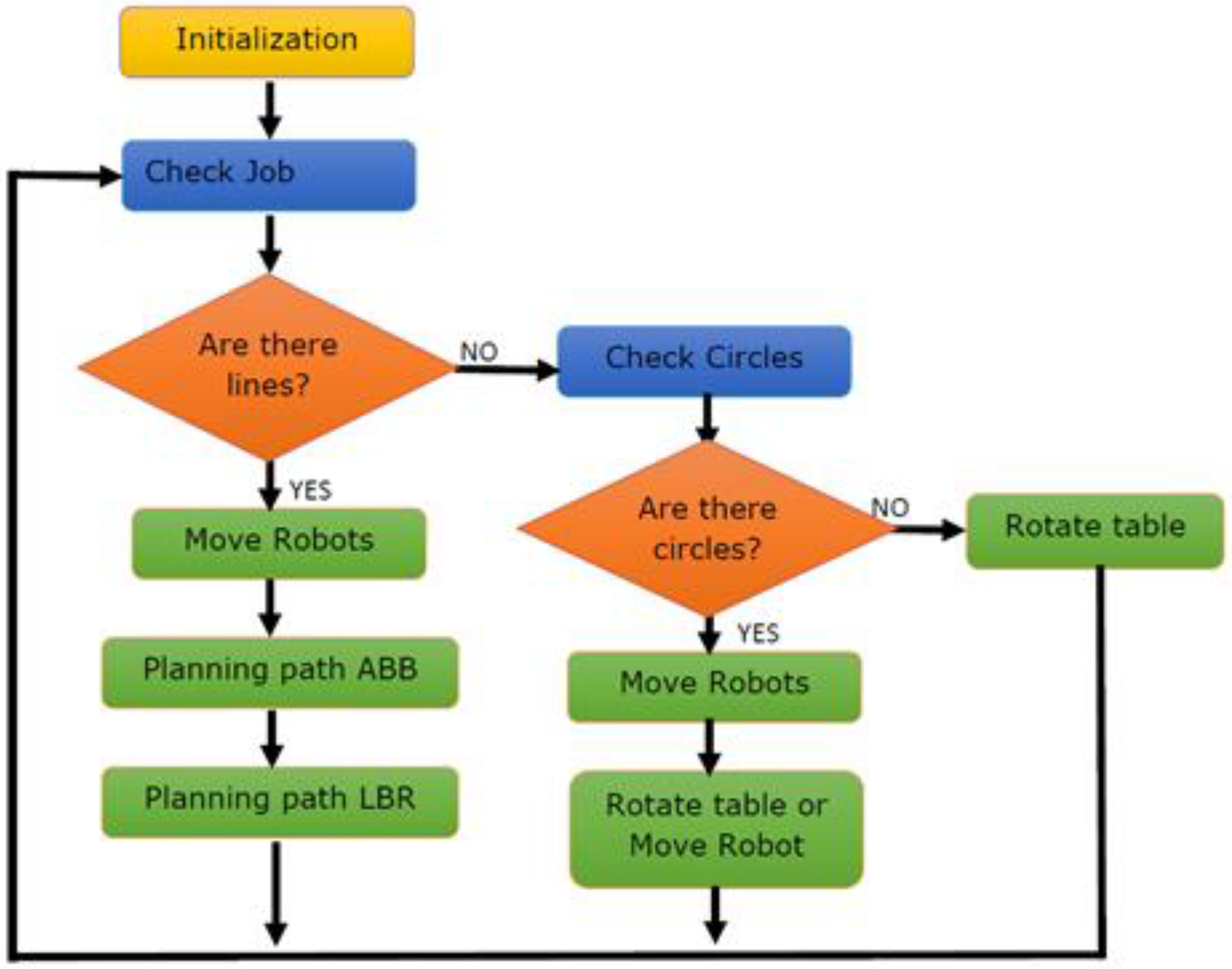
Figure 4 gives an overview of the structure of the implemented self-organization algorithms. After loading all weldline positions and process-related parameters from <ROS Param Server> during an <Initialization> phase, a <Check job> sequence followed to separate the types of welding tasks into the two classes of LIN and CIRC welds.
The algorithm starts with the LIN class and checks the location and orientation of the linear weldlines of the workpiece fixed on the turntable. In order to allow welding in a “gravity position”, the table orientation had to be always in a tilt position of 45°, as shown in
Figure 3. If one of the linear weldlines from the LIN class was detected and welding in a horizontal (gravity) position was allowed, MoveIt! took over responsibility through the transfer of the corresponding WeldStart position and continued to plan the robot motion in <Move Robots>. The selected robot to execute the weld in this context was always that one with the shortest Euclidian distance to the weldline at the time of the decision.
In our test application, typically two robots of different types have been considered for collaboration. Therefore, the self-organization algorithms in
Figure 4 include two path-planning activities controlled by MoveIt!, one for an ABB (Västeras, Sweden) robot, and one for a KUKA (Augsburg, Germany) robot (LBR).
In case a weldline in the horizontal position from the LIN class could not be found, the table was commanded to continue rotating in small angular steps until a weldline with an appropriate orientation was available. After all welds of the LIN class were finalized, welding of joints from the CIRC class followed.
Again, the self-organization algorithm started to access the CIRC class to check if the current orientation of one of the circular weldlines fit to an orientation in the horizontal (gravity) position.
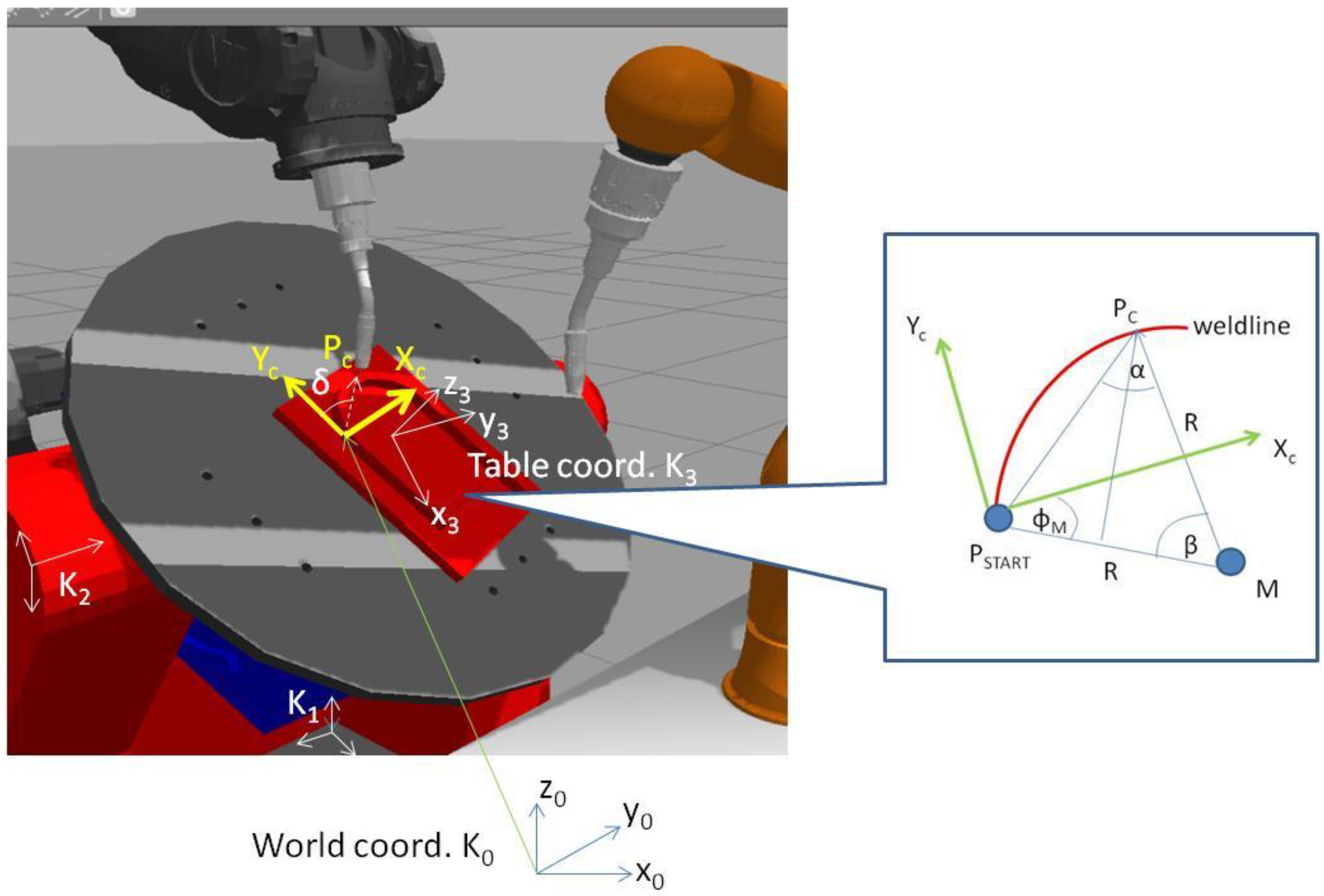
The gravity position was found in frame K1 of the turntable if the length of the WeldStart position vector in K1 is a maximum. In this case, a circular weldline in the gravity position has been found, and a robot of the team needs to be determined for welding task execution. The selection criterion was, again, the shortest Euclidian distance to the WeldStart position. As soon as the “nearest” robot was found, MoveIt! took over responsibility and started inverse kinematic calculations to enable the robot to move into the WeldStart position through input of the corresponding joint angles to the motion controller.
While the turntable remained in a fixed position, control points P
c on the circular path have been calculated. The reference was a local coordinate system K
c with the WeldStart position as the origin. The X
c-axis was defined as direction vector between WeldStart and WeldEnd. Z
C was directed in parallel to Z
3 of the table coordinate system K
3 according to
Figure 5.
By means of this definition, control points P
C(t) could be calculated along the circular weldline for any time t by:
where:
R = radius of the circular weldline;
φM = angle between XC und vector from PSTART to center point M of the circular path;
β(t) = angle between vector M_Pc and vector M_PStart; and
α(t) = angle between vector PSTART_Pc and vector M_Pc.
A coordinate transformation was necessary to transform the coordinates of P
c(t) into the coordinate system K
3 of the turntable:
Prior to the welding process in a gravity position with simultaneous movement of a robot and the turntable, an angle δ needed to be specified as the angle between the radius vector to
(3)P
START and Y-Axis of K
3:
With knowledge of δ and of the angle of table rotation Δδ per time interval Δt, any change of the control positions
(3)P(t) on the circular weldline could be calculated while the turntable rotates at an angular speed ω:
with:
After transformation from K
3 into the world-coordinate system K
0 by:
The welding of the circular path in a gravity position could be executed with a rotating table. The rotational speed of the table has been determined by the weld path length and the welding speed specified in the XML-based job description.
In case neither a linear weld nor a circular weld could be found in the gravity position on the turntable, the station control had to command the table to rotate by a certain angle (for instance: ±30°) until new weldlines from the list could be found in the gravity position for welding.
As soon as the weldgun has reached the WeldEnd position, rotation of the turntable stopped and the welding task was completed. The self-organization and planning algorithms continued with
Check Job (
Figure 4) until all joints were welded.
4. Autonomous Collision—Free Motion Planning
As recognized from the previous section, the algorithms proposed for self-organization and coordination of the work inside the robot team do not consider any trajectory planning to enable a proper and collision-free execution of the welding jobs being assigned to each of the robots. Therefore, especially for traversal movements from one weldline to the next, it was necessary to extend the self-organization and coordination functionality with appropriate resources for motion planning. As the most efficient tool for this motion planning task in ROS, we selected the integrated “Open Motion Planning Library (OMPL)” of MoveIt! to provide collision-free paths [
15]. From the library of motion planning algorithms provided by OMPL, “sampling–based methods” have been favored for the planning problem. Instead of a detailed construction of the configuration space, “sampling based methods” explore the C space by a sampling scheme. This means either: picking points in the C space randomly and storing the status of the robot at these points as knot of a search-tree, then creating a roadmap (learning phase) to find any shortest path between a given start and target position (query phase), or, alternatively, using a sequence of random sample-based motions on dynamically-feasible path elements to construct a search-tree and to find a collision-free path towards a target position.
The motion planning methods being used in our project addressed two of the most efficient methods. One of them was “RRT connect” (rapidly-exploring random trees) that allows a fast bidirectional search of a collision-free path (accelerated by factor 3–5 compared to the standard uni-directional RRT) [
16].
RRT is an algorithm that incrementally grows a tree from samples drawn randomly in a 3D search space. As soon as a sample qr is drawn, a connection is attempted between qr and the nearest, already-existing state qc of the tree. If this connection is feasible and represents a path free of collision, qr results in a new state of the tree. Normally, the length of the new connection between qr and qc is limited by a growth factor Δq. In case the connection between qr and qc is larger than this limit, a new state will be defined at the maximum distance allowed. Thus, the growth factor determines the rate of growing. Growing of the tree continues until a new qr has reached the target position and a collision-free path is found.
It is obvious that incremental sample–based path planning will take considerable time. To make calculations faster, “RRT connect” has been selected. Here, two trees, one from the start position and one from the target position are growing towards each other. States of the two trees can be connected through a path segment which fulfills the “shortest distance theorem”. In this way a collision-free path between start and target positions for any robot motion can be found much more quickly than with the standard RRT approach. However, both of the methods mostly converge to solutions that are far from optimal.
The second path planning procedure being applied in the project was “BKPIECE” (bidirectional kinodynamic motion planning by interior-exterior cell exploration). This has been selected to also consider dynamic constraints of robots [
17], especially when the URDF group node concept was used. The advantage of BKPIECE is that the dynamic behavior of the robots involved in the team are described by physical models and simulation instead of solving equations of motion. Furthermore, BKPIECE does not require state sampling and metrics to evaluate the distance between states, like in RRT. It applies path planning on the basis of trees created by forward propagation of motion. Random motion in the state space is performed. The start of motion is always related to state nodes already known in the search tree. Each search motion is limited by a fixed time interval (simulation step size) and intermediate states along each motion are generated at a fixed resolution (propagation step size). Based on these time frames, the dynamics of the robot in terms of speed, acceleration, impact of forces, friction, etc. during motion is investigated through physical simulation. If the dynamic parameters are within allowed limits and no collision with obstacles or self-collision is detected, then a new path segment of the search tree with a new node is established. To enable a fast search, exploration of the state space will be directed with high priority to areas which are covered less by nodes of the search tree. The calculation of the coverage is achieved by BKPIECE through discretization of the state space into grids with a fixed cell size. Envisaged are cells that contain only one new state node of the tree. To meet this goal the cell size needs to be adapted by further discretization levels until the convention of one node per cell is reached.
During planning with discretization of the state space, there are two types of cells to consider: “exterior cells” with less than 2n neighbor cells (n = dimension of the state space) containing projections of search motion, and “interior cells” with 2n neighbored cells covered by projections of nodes from search motions. For robot manipulators the spatial movement typically results in a three-dimensional projection.
During the first phase of path planning with BKPIECE, a significant number of “exterior cells” will be created, while after a certain planning time many “exterior cells” change their status into “interior cells”. To assure fast planning, as mentioned, BKPIECE will give priority to search operations in areas with “exterior cells” in order to cover the entire state space as quickly as possible. This strategy will increase the probability in finding a collision–free path from the start to the target destination.
Similar to “RRT connect”, BKPIECE offers further advantages because of search tree creation from two directions, from the starting point, as well as from the target position. This will guarantee faster motion planning and collision checks. Therefore, BKPIECE seems to be favorable especially for multi–robot applications
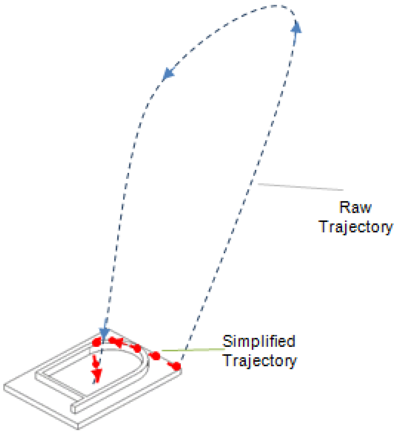
As planning procedures, in principle, consist of randomly-generated path elements or segments of motion which allow a dynamically feasible movement of the robots, it might take a certain computation time of a few seconds until a collision-free path is found. Similar to “RRT connect”, again it is underlined that, also with BKPIECE, the path being found is not an optimum. Sometimes it is too long or includes redundant movement. Therefore, a path optimization is required which aims either to minimize the path length or the travel time. In this context, in the project a “linear shortcut optimization” was applied in achieving acceptable planning results. It is achieved by trying to successively link path nodes via straight lines in the configuration space, test the new path element to avoid any collision, and replace the old path by the new one. After a few iteration cycles a simplified trajectory can be found (
Figure 6).
At the end of the planning process the paths produced by OMPL are translated by MoveIt! into dynamically feasible trajectories. Each point along the trajectories being found contains 3D position data in world coordinates and end-effector orientations in quaternion form. Therefore, to complete each planning cycle, inverse kinematics calculations have to be performed in the end to obtain the joint positions of the robots and match the desired poses. Depending on the number of attempts in finding a dynamically-feasible and collision-free path, and related to the number of joints and individual joint subdivisions of the robots involved in the team, computation requires some time. Therefore, it is obvious that the planning cycle times will have an impact on the performance of the team of robots in executing welding jobs through collaboration. A detailed study of this impact is the subject of
Section 7.
5. ROS-based IT Infrastructure for Motion Planning and Control
Based on ROS and MoveIt! services [
18], as well as on the self-organization functionality described before, an IT-infrastructure has been designed and implemented to enable autonomous planning as well as platform-independent control of the robot work in order to assure proper collaboration in executing predefined welding jobs.
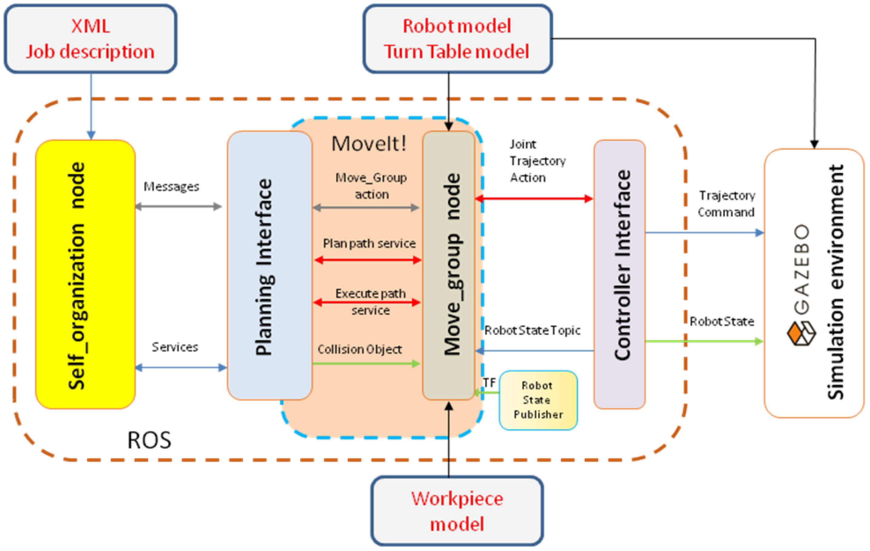
Figure 7 illustrates the proposed system architecture, recognizing MoveIt! as the key module of this infrastructure. Furthermore, modules for self-organization and coordination of the robot work, for the interpretation of predefined job descriptions, as well as for interfacing the ROS environment with external devices have been designed and added to enable communication, interaction, and control with real robots, peripheral devices, or even with a robot simulation tool like GAZEBO for monitoring and visualizing the team activities.
To save time and avoid costs for additional hardware and software to adapt communication and interaction mechanisms to real physical devices and safety requirements, priority within the project has been given to simulation studies with GAZEBO. It provides a powerful simulation environment for ROS applications [
19].
6. Interaction between MoveIt! and GAZEBO
To enable any interoperability between the ROS-based planning and control platform of
Figure 7 and GAZEBO, ROS as well as the simulation tool require information and model data of the robots, the turn and tilt table, and of the working environment. Therefore, a 3D model description in ROS was applied which was based on URDF (unified robot description format) files. URDF is an XML-based model description. Specifications related to kinematical structure, geometrical dimensions of mechanical elements, colors, mass moments of inertia, or other physical properties, such as friction, or even bounding volumes for collision checks are part of URDF.
For the project work, two heterogeneous welding robots of different size and kinematic structure (ABB Irb 6640 and KUKA LBR IV), as well as a two-axis turn and tilt-table have been selected and modeled by device-oriented URDF files to cope with any application in MoveIt!, as well as in GAZEBO.
Visualization and Control of Simulation
However, to assure visualization of the two robots, as well as of the turn and tilt table simultaneously, it was necessary to combine the individual URDFs of each device through grouping into just one file. This is because MoveIt! and the ROS Master Server, at its current state of development, can only work with one URDF file at a time.
The grouping of the individual URDF files of robots and the turn and tilt table could be achieved by use of the “XML macro concept” supported by ROS. The macro files are indicated through attribute <xacro>. Therefore, <world.urdf.xacro> had been used as a group node to support 3D visualization of all three kinematic devices, with only one URDF file. Additionally, with regard to the welding job selected to be executed by the team of robots, the corresponding workpiece model has to also be loaded into the URDF file and should be attached to the turn and tilt table to complete the model description for MoveIt!
In order to also apply <world.urdf.xacro> in GAZEBO, some additional GAZEBO-specific tags, for example in terms of material colors, collision specific data, inertial blocks, and transmission parameters (link actuators to the joints) had to be added.
After this extension, MoveIt! was now able to provide also the full configuration package to visualize any activity and interaction of the two robots and the turn and tilt table model. This has been achieved by the MoveIt! plug-in “RViz” (ROS Visualizer) and by the GAZEBO simulator.
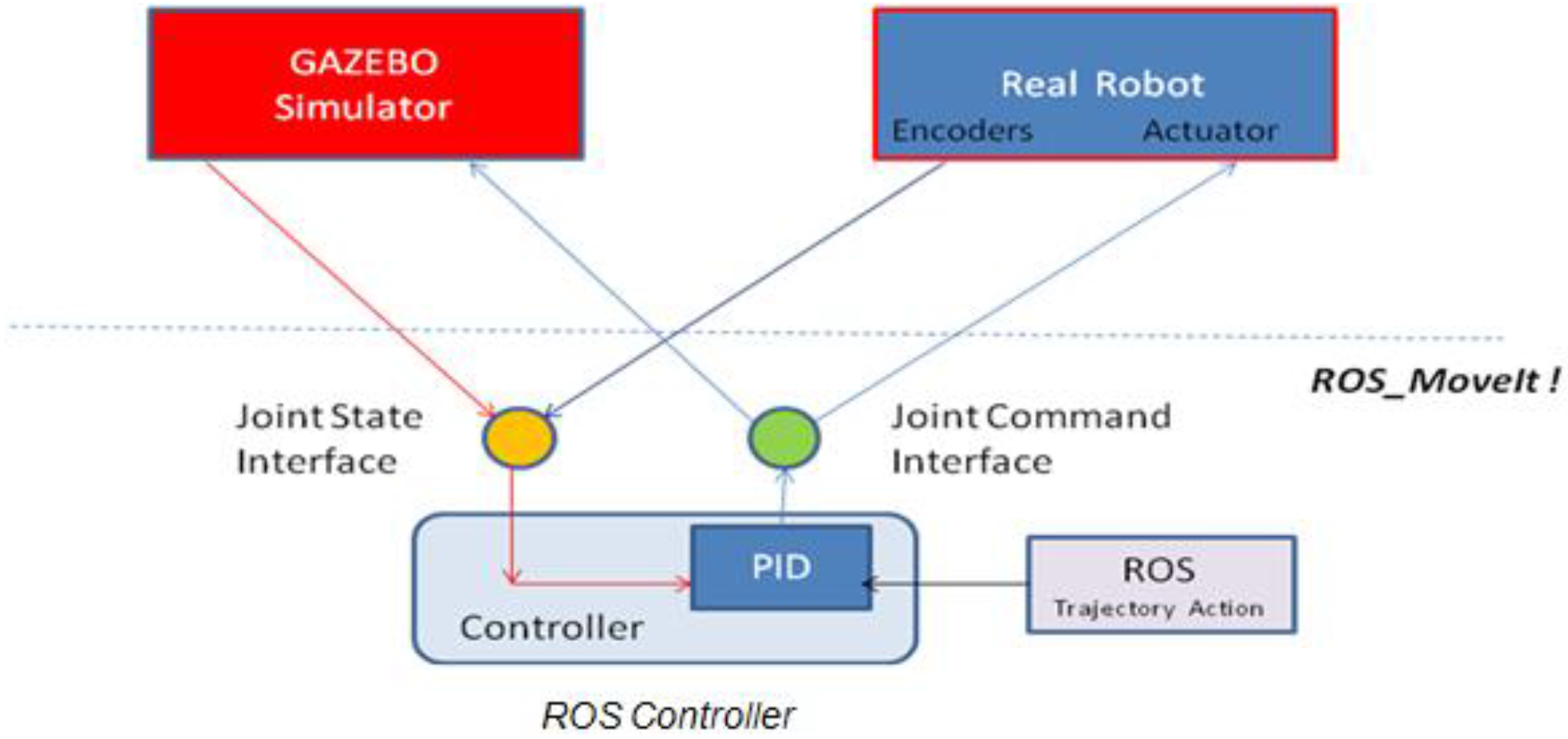
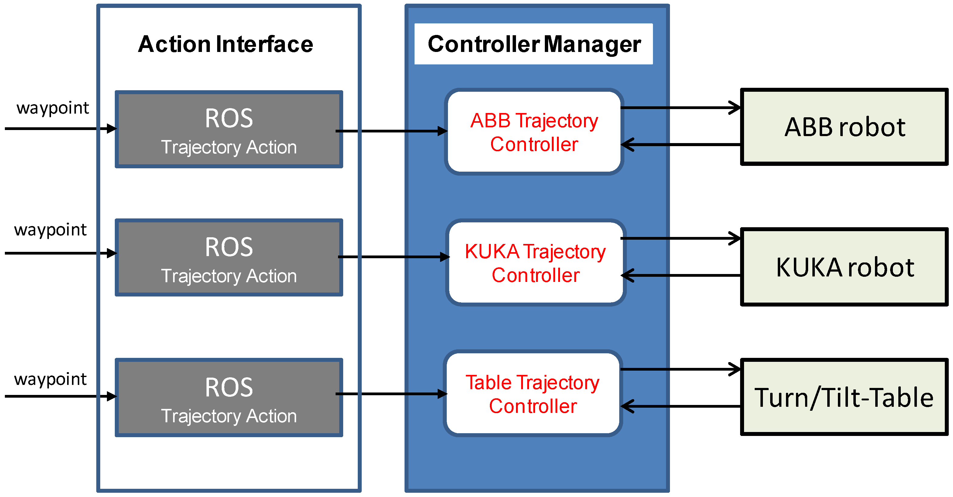
Nevertheless, full ROS integration with GAZEBO will be obtained if a controlled simulation of the robot teamwork is available. Therefore, mechanisms need to be specified on how to control any activity of the robots and table models in GAZEBO through ROS messages, services, and dynamic reconfiguration. For this purpose, a control interface node has been implemented. A key element of this interface was the “ROS control” plug-in which provides generic close-loop control, typically on the basis of a PID controller (
Figure 8). Inputs are the joint state data from the encoders of the robot’s actuators, and the waypoints generated by the trajectory planners of MoveIt!. As output, “joint position data” have been selected. They are used as feedback to the PID controller to control any motion of each individual kinematic device of the simulation scenario.
The ROS controllers are able to execute joint-space trajectories on a group of joints addressed by each of the robots and by the positioner. In order to pass the trajectory goals to the controllers, a so-called “joint trajectory action node” had to be implemented as an action server. The server reports success if trajectory goals are fulfilled and allows the definition of certain path and goal tolerances, like time delays permitted in reaching the target position, or path positioning errors that are acceptable during motion.
To manage the data flow between the action server and ROS controller, an infrastructure to start/stop and load/unload the controllers has been provided by means of a “controller manager” module. It is able to control the data transfer towards GAZEBO and can also connect MoveIt! to real physical robot systems, as indicated in
Figure 8 and
Figure 9.
As one action server is required per ROS controller, three action server nodes had to be implemented in the MoveIt! configuration to manage the data flow between the following entities:
ABB joint trajectory action ➔ Arm controller_ABB;
KUKA joint trajectory action ➔ Arm controller_LBR; and
Table joint trajectory action ➔ Axis controller_Table.
In this way action was brought to the respective controllers of the ABB and KUKA robots and to the turn and tilt table, which have been selected as the demonstration and test installation.
7. Simulation of Robot Collaboration
In order to start the execution of a welding job and to simulate how the team of robots will organize their work, gained from self-organization, self-coordination, and trajectory planning activities with MoveIt!, the <roslaunch> tool has been used to start the ROS nodes and to setup those parameters that are of relevance to realize a certain functionality. Content to be loaded is, for instance, the description of the robot models and of the turn and tilt table model. The model descriptions have been complemented by physical information related to the workpiece selected for welding (piece 1 or piece 2).
At system start, by default, all options related to the determination of the workpiece are disabled. Therefore, it is necessary to indicate the part which is to be welded. This can be achieved, for instance, by:
Other launch files have to be applied to load the XML description of the welding job and the GAZEBO simulation module, including the workpiece model (for instance: <piece 2>) as shown in
Figure 10.
Further launch files are also necessary to load the visualization in RViz, the trajectory controllers, the action servers, and the robot_state_publisher. As soon as all nodes, controllers, interfaces, and parameters are loaded, the links between ROS, MoveIt!, and GAZEBO are achieved and all nodes are prepared to run the application.
7.1. Results from Application Tests in a Static Working Environment
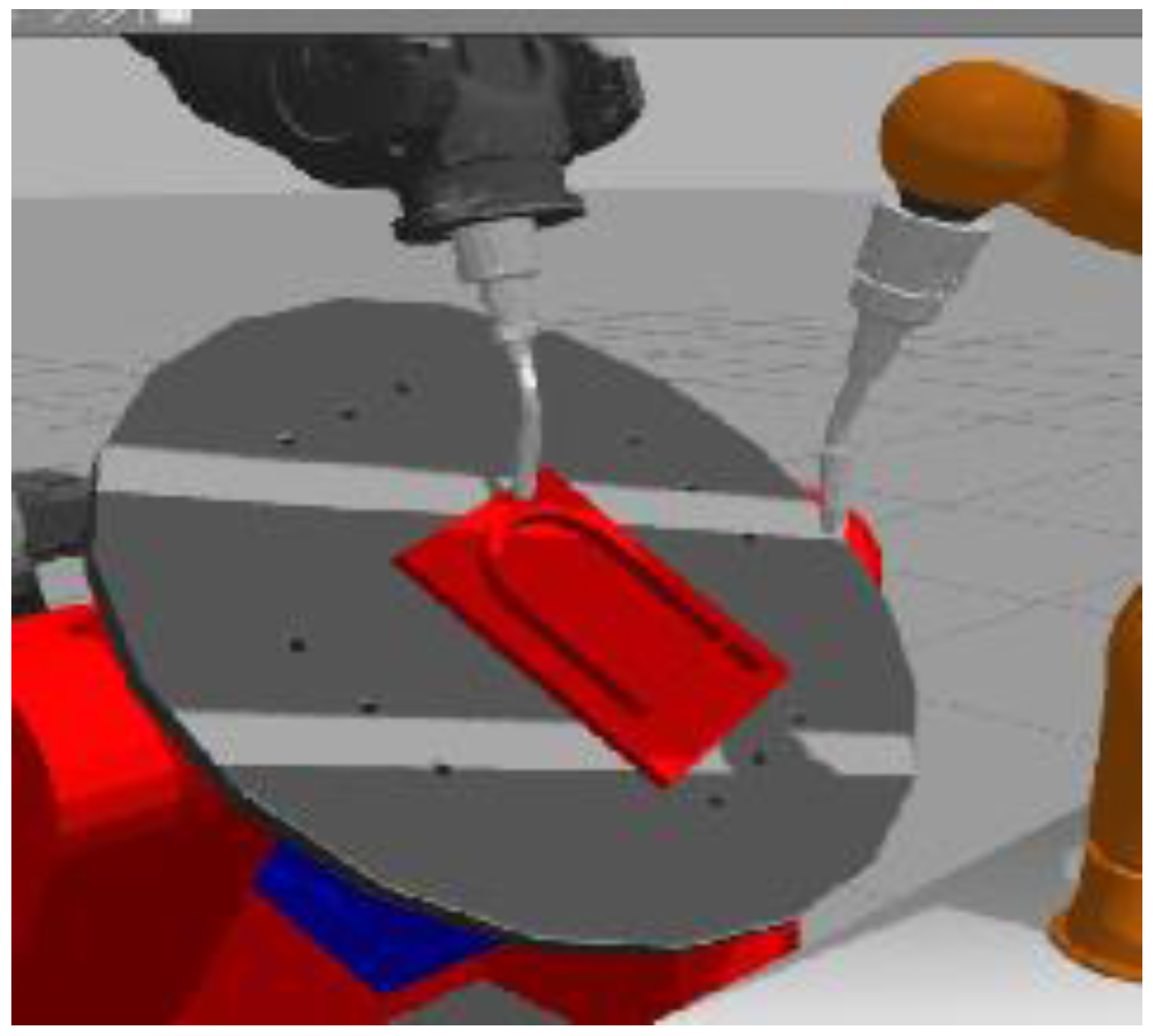
The applications scenarios selected to test the technical feasibility and to study the performance of our approach were focused first on welding jobs in a static working environment.
To start at a lower level of complexity, it was decided to compose the team of robots by two similar six-axis ABB manipulators. They should collaborate in executing defined welding jobs.
The geometry of the workpiece should combine linear as well as circular welds. Therefore, the table plate of the positioner model has been loaded with <piece 2> first, as shown in
Figure 10. The 14 joints to be welded within this application test have been positioned at a fixed orientation. The welding position was defined to be always horizontal.
According to
Figure 10, the positions of the two robots have been chosen close to the positioner, opposite to each. In this way the robots were forced to operate within overlapping work spaces when executing the welding job through collaboration.
As mentioned in a previous section, MoveIt! always used to start with the generation of an action list by evaluation of the XML job description. Then it continued fully autonomously in planning and organizing the work of the two robots selected for the test by calling the self-organization node first. The outcome were lists of activities being subscribed to each of the robots. Prior to this subscription, an optimization process was passed to meet economic goals by distributing only those series of welding tasks towards each of the robots, which assured a minimum of execution time.
The resulting sequences of activities subscribed to the two robots provided the input for MoveIt! in planning collision-free trajectories and to generate waypoints for the movement of the virtual robots in the simulation environment of GAZEBO. The planning procedures were performed in accordance to the technologies described in the previous sections.
All calculations and planning activities of MoveIt! have been performed in real-time to enable a fluent transfer of trajectory data towards the ROS controllers for controlling the movement of the robots.
In order to justify the performance of computational and planning efforts during self-organization and trajectory calculations in view of the demands for real-time control, and to understand the planning mechanism, time constraints, and restrictions MoveIt! had to cope with, a series of experimental tests have been performed.
Therefore, the paper continues with an overview of important results, as well as with experiences and first conclusions gained from various application tests. Focus has been given firstly to application tests in a static working environment. Results are presented in
Figure 11 and
Figure 12.
The diagram in
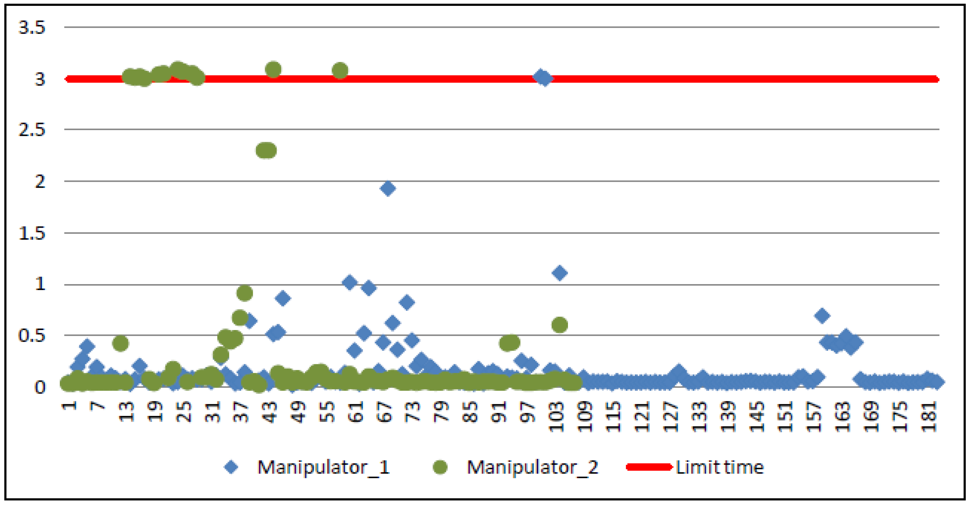
Figure 11 shows the different planning calls and times of planning activities performed by MoveIt! to execute welding of 15 joints represented by <piece 2>. The data are based on individual plans for each robot with the “RRT connect” planner.
To enable faster planning, the linear weldlines have been additionally split into 130 individual path segments of 0.015 m length, respectively, and into arc segments of 10°, in the case of the circular weldlines.
The time diagram indicates 184 planning calls for robot 1 and 108 calls for robot 2. In total we can see 292 path planning activities performed by MoveIt! within a time frame of 83.774 s = 1.4 min. The red line in the diagram represents a programmable time limit. All planning calculations beyond the 3 s limit were not considered by MoveIt!. They will not contribute to the planning process and start a new call automatically.
Out of the total 292 planning calls, 18 operations have to be considered for calculating collision-free trajectories to move the robots on traversal paths with point-to-point movement (PTP) mode, for instance, from one weldline to the next. Considering that 130 calculations were used to specify the movement of the two robots along the weldlines through interpolated control points, obviously 144 operations can be analyzed without any planning result. They have been aborted due to time overflow.
The overall planning time for robot 1 was measured to as 32.745 s, while the planning for robot 2 took MoveIt! 51.029 s. Reasons may be a non-balanced workload as result from the self-organization processes and perhaps more complex inverse kinematic transformations related to robot 2.
Nevertheless, the planning execution times measured for the two robots indicate that the total workload was shared and distributed to each of the two devices in accordance to the ratio of planning times. Therefore, as a result from the first application tests it could be demonstrated that the robot teamwork will reduce the total execution times of welding jobs considerably. Programming was done within 1.4 min. This is very fast compared to the standard “Teach-in” programming. In case of the two ABB robots (same type) which have been selected for the tests, a reduction of job execution time by nearly 50% can be observed due to collaboration. This is what we expected.
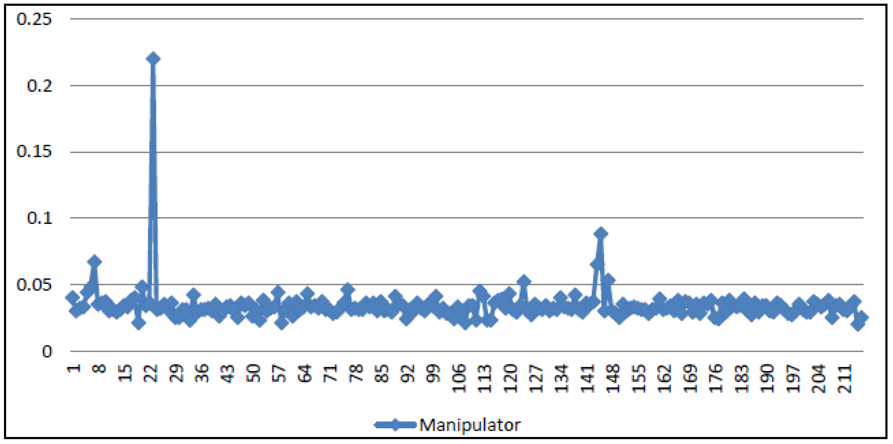
However, what about the planning efforts provided by MoveIt!? To be able to verify these efforts in organizing and planning the work of two robots in more detail, the same welding job was planned again but, this time, welding has been executed by only one robot. The resulting number of planning calls and the times for call execution are visualized in
Figure 12.
In
Figure 12 there are in total 217 planning cycles of different individual durations. Out of these 217 cycles, 130 cycles are considered for trajectory calculations along the predefined weldlines with interpolated waypoints. Four planning cycles were necessary to calculate the trajectories of the traversal movement from one weldline to the next, and for the return to the home position. According to this calculation, 83 planning cycles have been aborted because of collision problems and/or time overflow.
Compared to the time for planning the activities of two robots, now a resulting planning time of only 7.365 s in total could be measured. Most of the planning cycles need a time of around 0.02 s. This is 1/10 of the planning time MoveIt! has spent for path planning with teams of two robots.
Therefore, in view of these results, it might be favorable to focus on parallelism, if self-organization and autonomous path planning with MoveIt! for multi-robot applications is requested.
To verify this assumption in more detail, tests have been continued, but now with more complex application scenarios.
7.2. Results from Application Tests in Dynamically Changing Working Environments
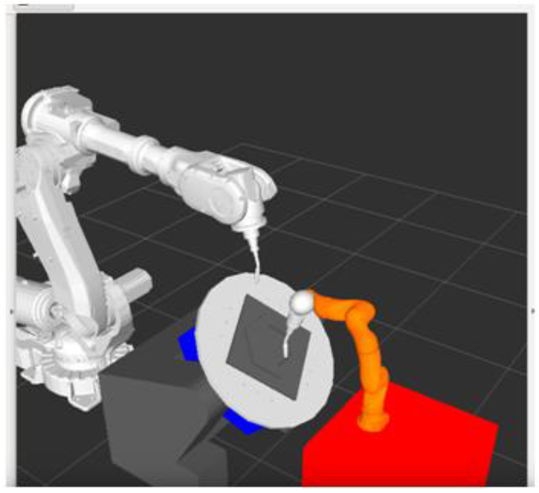
To verify the performance of self-organization, self-coordination, and autonomous collaboration at higher levels of complexity, a series of tests have been carried out together within a new test scenario. This is shown in
Figure 13. Instead of two robots of the same type, now two completely heterogeneous welding robots (ABB, six-axis and KUKA, seven-axis) and a controllable tilt and turn table (two-axis) have been applied to test and prove the technical feasibility of our approach. <piece 1> was selected first because of its simple geometry and its linear fillet-type weldlines.
As it was foreseen that welding should always be performed in a gravity position during application tests with dynamically changing conditions, the turn and tilt table had to be oriented from a loading position (
Figure 13b) towards an angular table position of 45° (
Figure 13a). Furthermore, an incremental reorientation of the workpiece during job execution was required to assure weldlines were always positioned in a gravity position prior to welding.
Based on the list of actions derived from the corresponding XML job description the system, again, started to plan and organize the activities of the two robots and of the tilt and turn table fully autonomously. This happened in accordance to the self-organization algorithms and rules described in
Section 3.2.
While the planning was progressing, the list of actions has been continuously decreased depending on the activities already having been realized. They were deleted from the list after execution.
As the joints to be welded at <piece 1> always represent straight lines in the horizontal position, the Cartesian path between WeldStart and WeldEnd at each joint could be planned through a list of waypoints being interpolated at path segments of 10 mm per interpolation cycle. The generated path did not need to be simplified, since it was already the shortest path to be found in the Cartesian space.
As described, it was the task of MoveIt! to plan the trajectories for the movement of the robots and to check for collision, either between the robots and the workpiece, or between the robots themselves. In case a collision was predicted by MoveIt!, the planning process was aborted and a new attempt was started to find a collision-free path. Therefore, especially in complex application scenarios being applied for testing, the planning processes can be time-consuming and may result in varying computation times. This phenomenon is recognized in the time diagram of the planning process presented in
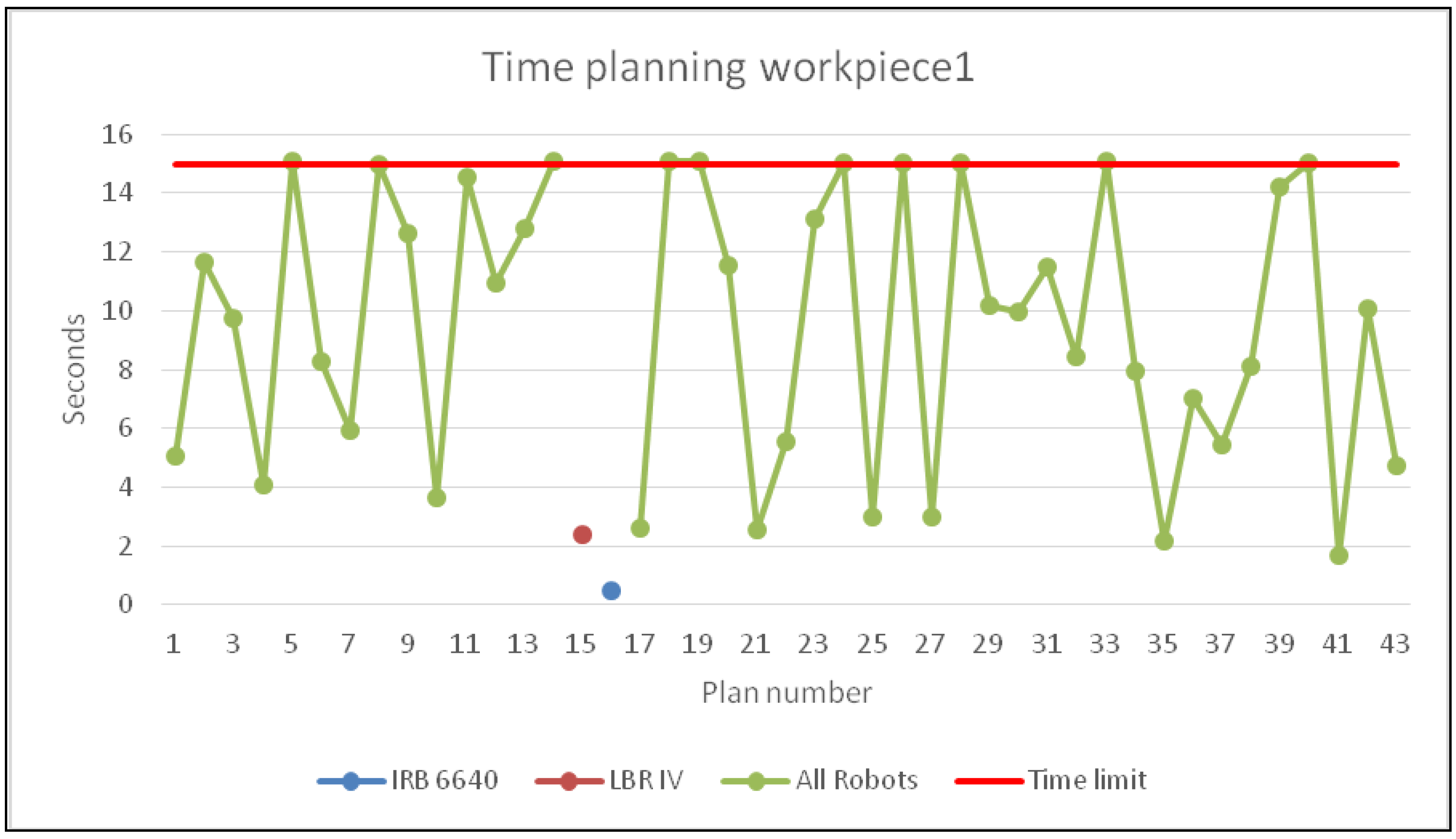
Figure 14.
The planning of the welding job to enable collaboration of the two robots and a tilt and turn table (15 axes of motion in total) took MoveIt! 43 planning cycles as indicated in
Figure 14. Compared to the application tests described in
Section 7.1 with individual motion planning, now the planning procedures have been carried out by applying the URDF group-node concept (see:
Section 6) and use of a “BKPIECE” planner. A threshold of 15 s (red line) was defined to abort a planning cycle due to time overflow.
According to
Figure 14 an average planning time of in total 395 s = 6.6 min was measured. Nine planning cycles had been aborted due to time overflow. In one case it was necessary to call the individual motion planners for the ABB and the KUKA robot (blue and orange points) because of a lack of results from calculations with the group-node concept. Finally, 15 s of the total planning time were spent for trajectory optimization activities.
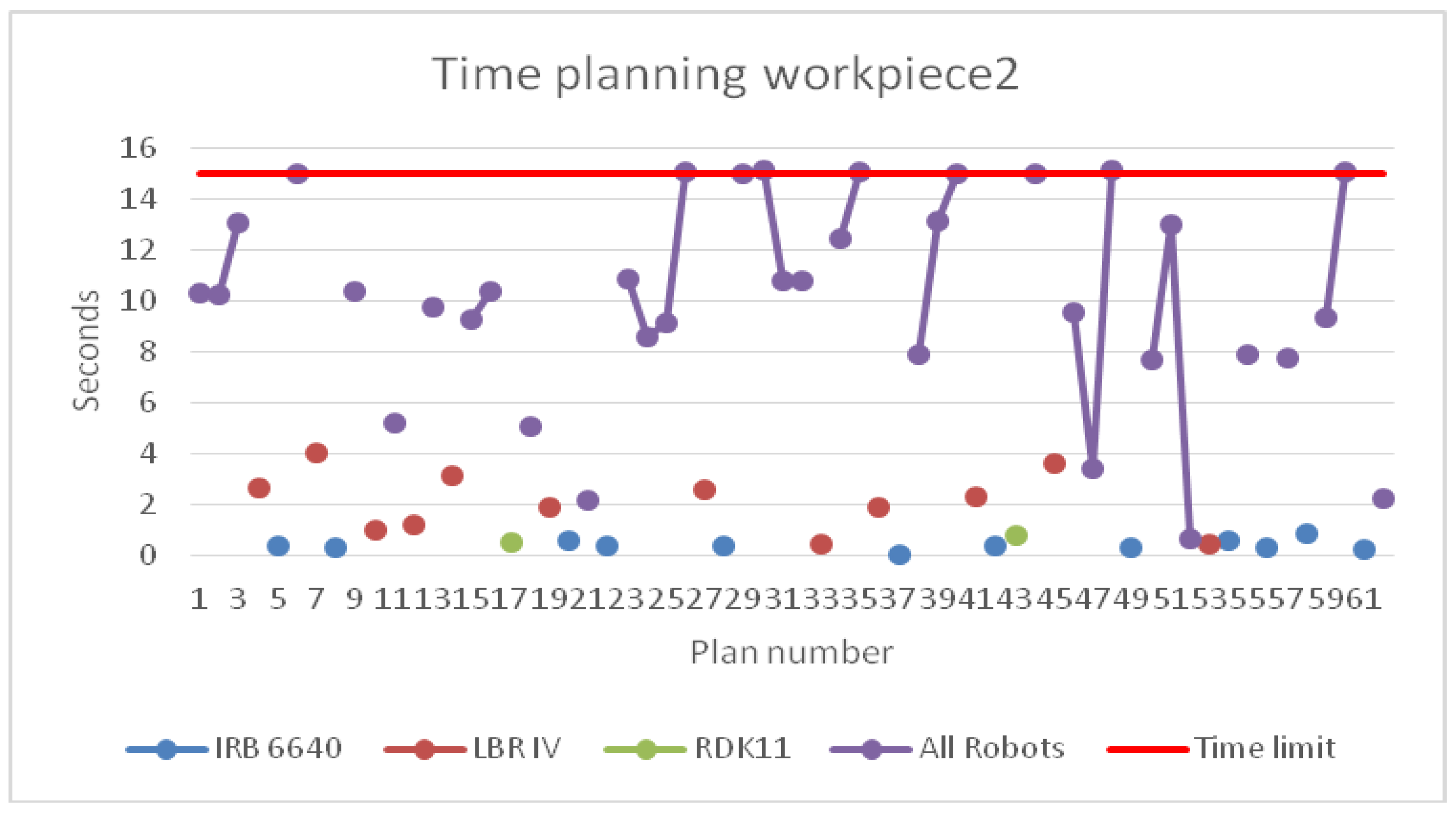
Then the degree of complexity has been increased again by selection of an application scenario to weld <piece 2>, which included a composition of linear and circular weldlines. As shown in
Figure 15, it took MoveIt! 62 planning cycles of different times to plan the collaboration inside the team of robots. The total time to plan the activities of robot 1 (ABB), robot 2 (KUKA LBR), and of the three-axis turn and tilt table was 398 s, i.e., 6.6 min. Nine motion plans were aborted. The loss of time related to the aborted plans was around 136 s. Furthermore, 8 s were necessary for path simplification.
Although the group node concept with <world.urdf.xacro> and the BKPIECE path planner have been applied initially for trajectory planning, individual planner calls based on “RRT connect” to solve planning problems are often recognized because of aborted calls with the group-node concept.
The planning of the turn and tilt table movement appeared as an individual planner because of the CIRC welds, which required a constant table rotation while the circular weld path had to be tracked by one of the robots.
7.3. Evaluation of Real-Time Simulation
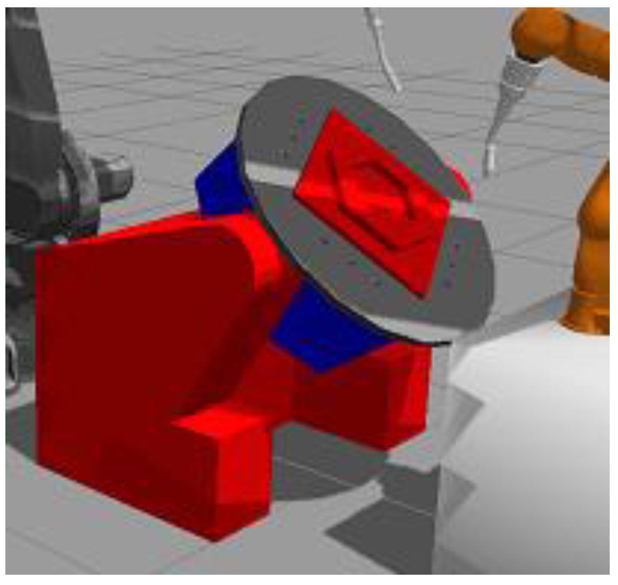
As the collaborative work performed by a team of robots in cooperation with a turn and tilt table has been visualized and evaluated by means of real-time simulation (
Figure 16), sometimes it could be recognized that the planning took too much time to calculate the inverse kinematic solution for the entire system of 15 axes in a desired position.
In this case, planning was divided per robot and was calculated individually. This resulted in simulation sequences where only one robot at one time was executed. The reason was, as already mentioned, that the ROS Master Server and MoveIt! are only able to support path planning by means of only one URDF file at a time.
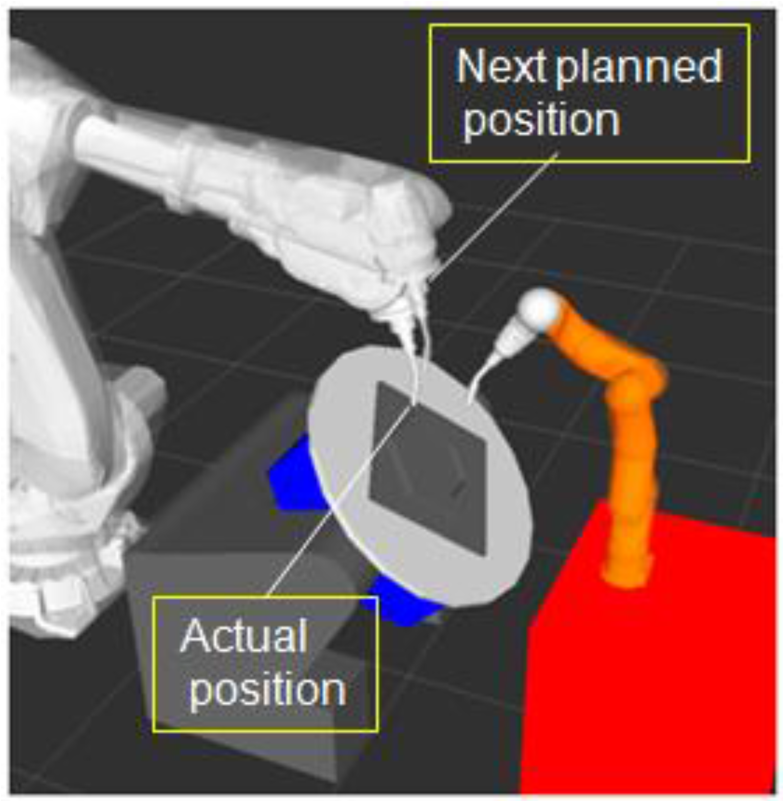
During simulation, to visualize was also how the path planner and MoveIt! have planned to continue the next movement of the robots in the configuration space. For this purpose the motion planning offered an animation before execution of the movement. A “shadowed” robot, shown in
Figure 17, represents the trajectory to be executed next, while the real robot model has been visualized in its actual position.
As soon as the planning result was evaluated and released by MoveIt!, the trajectory data were transferred to GAZEBO and the simulated robots moved. In this way the quality of planning results could be studied in detail if necessary.
Due to the different cycle times during trajectory planning with MoveIt!, but also because of the variations in motion execution which were influenced by the communication and data transfer speed between MoveIt! and the GAZEBO simulator, the measurable total times of welding job execution in the simulation were not applicable to predict any execution times to be expected in reality.
However, GAZEBO has been very useful in demonstrating the technical feasibility and applicability of our approach. It also provided powerful tools for studying the performance of self-organization and autonomous planning in obtaining collision-free and executable trajectories for a coordinated and controlled execution of given welding jobs through collaboration by teams of industrial robots.
By application of the URDF group-node concept in trajectory planning, it was possible to control and move the simulated robots simultaneously. However, as soon as the group-node concept failed in finding executable trajectories, individual planners per robot had to be used to replace them. Fast solutions have been achieved, but only with simulated movements, robot by robot.
7.4. Interface Concept to Control Real Physical Robots
The MoveIt!-based motion planning concept developed in the project was able to generate not only trajectories and waypoints to control the movement of the robot models in a simulation environment of GAZEBO. The output of the planning procedures was also applicable for the control of real physical robots being connected to the ROS planning and control environment shown in
Figure 7. For this purpose, the “controller interface“ needs to be extended on one side by hardware modules, like real-time Ethernet and a TCP/IP network to support communication and, on the other side, by software that has to be implemented to transform the output data from MoveIt! into a robot-specific machine code, as well as to feedback data from the robots to MoveIt!
For communication with the KUKA robot LBR IV, the “KUKA Ethernet KRL XML” package can be used. It supports data exchange through the use of XML messages.
For ABB robots the appropriate hardware for networking has to be established. Furthermore, a special software converter has to be developed and integrated into the controller interface of MoveIt!. This wraps the waypoint data from MoveIt! into messages of defined syntax and cares for the transmission to the ABB robot controller. By means of the “READ” task, provided by the ABB controller, strings of a maximum of 80 characters can be decoded to start the defined robot programs inside the ABB controller. A “SEND” task can be used inside the ABB controller to send messages to the ROS world. In this way bi-directional communication can be achieved and managed.
However, the connection to real physical robots, which will replace the GAZEBO simulator, was not part of the project and, therefore, a topic of future work.
8. Conclusions
The proposed ROS-based concept with integrated self-organization, autonomous trajectory planning, and simulation capabilities offers new perspectives and advantages in applying collaborating multi-robot systems for welding automation purposes. Even if the robot teams are composed of totally heterogeneous machines, with ROS it could be demonstrated that just one programming language is sufficient to support direct communication and any interaction between them. This makes control and collaborative automation easy and fast to implement.
It became obvious during the project work that ROS and ROS-based software functions, available as open source products, can provide a suitable platform for developers to implement powerful and intelligent solutions capable of applying and controlling industrial robots in special application scenarios and advanced automation concepts.
User input to operate multi-robot applications could be reduced considerably by our approach. Instead of complex programming and synchronization, now it is focused more or less on the description of the manufacturing job to be executed by the robots.
The results achieved so far from extensive application tests and performance studies have demonstrated the technical feasibility of our approach, in principle.
The selected algorithms for trajectory planning, represented by “RRT connect” and “BKPIECE”, are able to create fast results at acceptable planning times. Individual trajectory planning for one robot with “RRT connect” could be performed within seconds for an entire welding job of, for instance, 14 welds and four PTP-based traversal movements. This is a very promising result which should stimulate follow-up research.
An increase of planning time could be recognized as soon as the number of robots and additional peripheral kinematic systems, like multi-axis workpiece positioners, are considered for collaboration. Especially, inverse kinematic calculations, as well as more extensive collision checks, will extend the planning times. However, sufficient planning results and smooth control can be expected from our approach, if applications are restricted towards teams with only two or three robots, respectively, with kinematic devices of up to a maximum of 15–18 DOF.
In addition to individual trajectory planning calls per robot, the group–node concept with grouped URDFs has been introduced and tested. Its application resulted in a decreased number of planning cycles or calls, but at increased planning times per call due to more complex collision checks and inverse kinematic transformations. If those calculations with the group-node concept can be achieved without any time overflow, a smooth and collision-free interaction of the robots can be expected as demonstrated in
Figure 14. However, at increasing complexity of the calculations and planning efforts, the URDF group-node concept will lose its applicability because of increasing numbers of planning calls with time overflow. The growing dominance of individual planning activities should be recognized, in this case, as shown in
Figure 15.
Therefore, future work should be focused on technological improvement and better applicability. A promising approach seems to be the implementation of parallel planning activities as soon as the number of robots or peripheral devices increases towards the defined limits and beyond. Operating with individual ROS frameworks and motion planners per robot is recommended in this case. A ROSTCP-based communication infrastructure to assure gapless interaction inside the team is to create. Additionally, useful could be the implementation of a pre-calculus for motion planning and collaborative control as one instrument for further improvement.
In view of the goals and visions of Industry 4.0, which had stimulated our project, the outcome achieved so far demonstrates how cognitive functions and autonomy may open new perspectives towards the development of intelligent machines and advanced automation concepts. In this context the frameworks of ROS and industrial ROS can offer excellent tools, functions, and open source software, especially applicable for research and technological development in the field of robotics and robot applications.
The technical approach on self-organization and autonomous path planning, developed to improve the applicability of robot teamwork and collaboration in welding automation, may also contribute to meet the goals and visions in developing intelligent machines that will help humans to master the challenges of the future.

