Review

The Insulation for Machines Having a High Lifespan Expectancy, Design, Tests and Acceptance Criteria Issues

1
Rectorat de Lille, Clg DESCARTES, 2 Rue Lavoisier, 59370 Mons-En-Baroeul, France
2
Engineer & Member of the AREVA College of Experts & Referent Expert in Electromechanical, AREVA NP, 27 Rue de l’Industrie BP 20189, 59573 Jeumont CEDEX, France
*
Author to whom correspondence should be addressed.
Machines 2017, 5(1), 7; https://doi.org/10.3390/machines5010007
Submission received: 9 September 2016 / Revised: 19 November 2016 / Accepted: 26 November 2016 / Published: 20 February 2017

Abstract

:
The windings insulation of electrical machines will remain a topic that is updated frequently. The criteria severity requested by the electrical machine applications increases continuously. Manufacturers and designers are always confronted with new requirements or new criteria with enhanced performances. The most problematic requirements that will be investigated here are the extremely long lifespan coupled to critical operating conditions (overload, supply grid instabilities, and critical operating environments). Increasing lifespan does not have a considerable benefit because the purchasing price of usual machines has to be compared to the purchasing price and maintenance price of long lifespan machines. A machine having a 40-year lifespan will cost more than twice the usual price of a 20-year lifetime machine. Systems which need a long lifetime are systems which are crucial for a country, and those for which outage costs are exorbitant. Nuclear power stations are such systems. It is certain that the used technologies have evolved since the first nuclear power plant, but they cannot evolve as quickly as in other sectors of activities. No-one wants to use an immature technology in such power plants. Even if the electrical machines have exceeded 100 years of age, their improvements are linked to a patient and continuous work. Nowadays, the windings insulation systems have a well-established structure, especially high voltage windings. Unfortunately, a high life span is not only linked to this result. Several manufacturers’ improvements induced by many years of experiment have led to the writing of standards that help the customers and the manufacturers to regularly enhance the insulation specifications or qualifications. Hence, in this publication, the authors will give a step by step exhaustive review of one insulation layout and will take time to give a detailed report on the standards that are linked to insulation systems. No standard can provide insurance about lifespan, nor do any insulation tests incorporate all of the operating conditions: thermal, mechanical, moisture and chemical. Even if one manufacturer uses the standards compliance to demonstrate the quality of its realization; in the end, the successful use in operation remains an objective test. Thereafter, both customer and manufacturers will use the standards while knowing that such documents cannot fully satisfy their wishes. In one 20-year historical review, the authors will highlight the duration in insulation improvements and small breakthroughs in standards writing. High lifespan machines are not the main interest of standards. A large part of this publication is dedicated to the improvements of the insulation wall to achieve the lifespan. Even if the choice of raw materials is fundamental, the understanding of ageing phenomena also leads to improvements.

1. Introduction

The asynchronous machines (AM) are electrical machines which are used in systems where reliability is set as the first requirement. The robust design of their squirrel cage rotor dramatically improves their lifespan. This is one reason why they account for more than 90% of electrical motorization of critical systems, including, for example, the primary coolant pumps in nuclear power stations. Even if this type of rotors does not contain materials that are chemically unstable, this is not the case for stators that have a winding insulation. Several studies (done by IEEE: Institute of Electrical and Electronics Engineers, EPRI: Electric Power Research Institute, IEC: International Electro technical Commission, etc.) and REX (Return on EXperience—data coming from motors in operation) into the reliability of motors conclude that insulation defects are the first reason for machines outages. Insulation design is an arduous job. Two separated domains can be identified. The first one is the domain which is covered by the standards such as IEC, IEEE, NEMA, IS (Indian Standards) or BS (British Standards). In this field of interest, the conditions of use are not described in detail and the period of guarantee, where the supplier is in charge of defects, is short compared to the expected lifespan (2 years compared to a 20-yearlifetime). The second domain of interest is about the systems which need an extremely long lifespan (40 years and more). In this field of interest, all ageing events are carefully investigated during the design and manufacturing stages. This means that each event or criterion which are described have to be examined and integrated into the design of the machine. That is a hard job for the customer who is in charge of writing the specification. This is also a hard job for the designer who has to comply with these specific criteria. However, it is not correct to imagine that such activities are in oppositions. In introducing an unrealizable condition in the specifications, the customer will have a negative influence on the design and especially in its price, which could dramatically increase. Engineers who are in charge of writing specifications must have a good overview of the machine design, their necessary performances, manufacturing processes and procedures. The manufacturer must keep in mind that requirements are coupled to penalties if they are not satisfied. It is not always a good idea to promise everything. Hence, customers, in requiring unrealistic performances will induce an incredible increase in prices and the manufacturers that will accept unreachable performances will induce financial penalties at the final step. Looking at the reliability of electrical machines, insulation is one of the most important elements: any fault in design or during manufacturing can result in a dramatic impact on the lifespan and it is not always possible to discover this during the factory acceptance tests. Insulation is one element which is very difficult to design: everyone wants a low number of acceptance criteria and wants specifications which are adequate to insure the compliance of the machine. Even if advices are provided by standards such as IEC 60505, such standards do not provide exhaustive procedures and acceptance criteria which can meet all needs of the customers. To describe such a complex situation, authors have separated this publication into several sections which are as autonomous as possible. The first chapter introduces the arrangement of elements in the insulation wall. It introduces at the same time its dramatic impact on lifespan and provides the first analysis of standards. The next chapter begins with the conclusion that was reached previously. If the lifespan of a machine must be improved, all the influences of ageing parameters and their modeling must be analyzed. Thereafter, it appears that several standards can provide usable data or models but are not able to insure the lifespan as most of them do not accept the mix of ageing parameters. Nevertheless, standards obviously provide a technical base and a methodology that have to be followed. The next section introduces a historical example. This example is used to demonstrate the difficulty in undertaking improvements of insulation. Innovations can be considered as having a positive impact at one time and the effect of this can be reduced a few years later. Standards organizations are in awaiting any ideas that can initiate improvements that can be a benefit for everyone. However, about lifespan, they must wait a long time in order to conclude whether suggested improvements are worthwhile. Nevertheless, the role of standards is not in describing the manufacturing or design process but rather in the precise writing of methods or measurements which can provide without any question an incontestable opinion on the performances of the system. This is why the standards have retained one of the pieces of apparatus built by Fuji-Electric during the last 60 years. Such an apparatus has initiated the partial discharges diagnostics. Thereafter, the authors highlight other improvements, which are linked to manufacturing processes and are currently in use but are not cited in the standards. The next section comes back to the insulation system and points out its weakest part. Due to the structure of the insulating wall that has been defined throughout the past 50 years, the use of polymer resins is unavoidable. Improvement in lifespan is directly linked to resin improvement and its using in manufacturing process. This section demonstrates the main drawback of the resin: It is an organic material that evolves over time and that does not appropriately behave in front of thermal aging. Nevertheless, manufacturers have to live with and they have imagined processes, such as the VPI (Vacuum Pressure Impregnation), which can overcome some drawbacks. The fifth section takes into account the knowhow which can improve the insulation lifespan. At the end, the best manufacturing process will be the one that does not make any errors. The authors, step by step show the difficulty of obtaining a “good” insulating wall. The standards only provide objective measurements and skilled persons are required to interpret the results. Hence it will appear that invalidated tests can pollute the acceptance process. In this section, a large number of potential defects are investigated and the methods used to mitigate them are presented. The methods can depend on manufacturing process but also can depend on design process. At the end of the publication, the last section focuses on several well-known issues which are still relevant.

2. Insulation System in HV Stator (Form Wound)

2.1. Environment Overview of Insulation Systems

The electrical machine insulation can be damaged by many factors which are currently indicated by a coding including the severity of the environment. There is not always a specification or a criterion for each code. This coding is listed through six letters and one digit. The general description of the insulation system codes is given in Table 1. All these factors are recognized as ageing parameters. For example: letter D, used for the machine Duty cycle, has been identified as having a great impact on the ageing of the insulation. An electrical machine, having several run/stop in a day, is more subject to abrasion of insulation. The machines used for base load operation are not so stressed. Nevertheless, all factors have not been studied with equal importance. Therefore, when a parameter has a little studied effect, manufacturers and customers are helpless for taking it into account. There are not standards or technical sheets to solve the issue. However, the main ageing factor, which is well-known, is the thermal aging. Many standards exist and provide procedures and test methods for estimating the lifetime of an insulating system submitted to thermal stress (Ul-746, UL-1446, IEC-60216, IS-11182, etc.). Many other factors cannot be well-quantified and should be studied later. For example, the customer does not always know how many times his machine will operate under overvoltage or overload conditions as well as their duration. Studies periodically confirm that thermal aging is responsible for the greatest number of outages [1] and subsequently, a good method to initiate the design of electrical insulation is to first deal with the effect of thermal aging. Thermal aging does not apply to all elements of an insulation system. All the elements or materials used do not have the same behavior in front of this constraint. Hence, it may be possible to increase the expected lifespan of an insulation system by modifying only one of its components: the weakest one. The constitution of insulation wall must be examined, and, in particular, the arrangement of the insulation layers in machines which should have a high service life. These machines are essentially high voltage machines. They use a well-known insulation system which is composed of 3 elements that will be presented thereafter.

2.2. The Specificity of High Voltage Insulation System, Functional Aspect

The insulation of a high voltage winding can be seen as copper strands wrapped by insulation layers. The numerous insulation tapes surrounding the copper strands are not set up in random. The tapes are applied butt-lapped or overlapped. Two tapes make a layer. The coil insulation located inside the slots of the stator core and the insulation located outside the slots are subject to different constraints. For this reason, the authors dissociate their analysis into two parts. Depending on the winding design, the coil turn can be composed by one wire or several wires; each wire is insulated by insulation layers. Hence each wire can be covered by turn to turn insulation or by strand insulation with an additional turn to turn insulation. The turn to turn insulation has two aims, the first one is to achieve an insulation between turns (low thickness as the voltage between turns is very low) and the second is related to the electrical surges caused by lightning stresses, electrical surges induced by DOL Switch-Off/Switch-On or electrical stresses generated by circuit breakers and IGBT [2]. The standards, IEC and IEEE, request that turn insulation must be able to withstand a surge pulse. In observing the IEC standard, the test voltage is 0.65 times the surge voltage (4 Un + 5 kV) and the rise time is around 0.2 μs. The surge test also takes into account the main insulation; it must be able to withstand a surge (4 Un + 5 kV) rise time 1.2 μs. The case of one turn composed of more than one wire is usually encountered when the copper cross section is too large to be bent. Such a turn is achieved by putting elementary wires of smaller section in parallel. In this situation, it is preferable to apply a thin insulation for electrical separation of the elementary wires composing the turn and additional insulation designed to withstanding the surge voltage (Figure 1).
Thereafter, the main insulation layer is added. Its thickness is designed according to the voltage supply. The main insulation exists in the stator slot and outside the slot. In case of voltage supply greater than 6 kV, additional layers are added. In the stator slot, this last layer is a conductive layer, namely Conductive Armor Tape. Its aim is to ensure the same potential along the coils: the ground potential (Figure 2). Such a layer seals the main insulation in the slot. Even if this layer is considered to be a conductive layer, designers should not select a tape with a low resistivity. Looking at the situation, the Conductive Armor Tape covers the entire slot surface. This means that such a layer can close the electrical circuit provided by two adjacent silicon iron sheets which are in the stator core. Eddy currents may appear in the stator core and may deteriorate this conductive layer. A low resistivity material induces high eddy currents which will age this layer and such a case is not favorable for a long lifespan [3]. Hence, the resistivity of this layer has to be chosen in accordance to the resistivity of the main insulation. A few kΩ for Conductive Armor Tape is a good choice. This can set the potential of this layer to the ground potential without any doubt. The main controversy is the minimum resistance of the surface. Two researchers, Liese and Brown, have studied in large air-cooled generators, the vibration sparking. Such events have been caused by a too-conductive coating in the Conductive Armor Tape [4,5].
Outside the slot, the question is different. The windings do not touch the iron parts that are at ground potential. Hence, there is no need of a conductive layer. But, a high level of electrical stress appears at the end of the Conductive Armor Tape. The electric field in this area is large enough to initiate corona discharges that will rapidly age the insulation. Air can sustain an electrical field, if this one exceeds a value, an electrical discharge appears. Outside the insulation wall, it is called corona discharge. If such a discharge appears in the insulation wall, it is called partial discharge. The authors will investigate more precisely on the last phenomenon at the end of the article. Excess in discharges will lead to outages in a short time. The well-known solution for machines supplied by a supply voltage greater than 6 kV is the use of a semi-conductive layer which will scatter the electrical field and reduce the maximal electrical stress induced by the Conductive Armor Tape. The stress-grading issue will be described later in the article, here, only the functional aspect is presented here. This stress-grading (semi conductive layer) is not applied over the entire part of the end windings but only over a short section (Figure 3). The manufacturing process involves a bending of coils to adapt the coils to the geometry of the stator and allowing their insertion in the slots. It is usual to have, for this part of winding, an excess of insulation thickness or some folded tapes. When such a work is done by hand, a lower wrapping quality is encountered [6]. Even if such coil parts are not in the slot, they also need to be manufactured with care.

2.3. The Design of High Voltage Insulation Systems and the Main Raw Materials

The design of one insulation system is the result of many years of experimentations and investigations on machine failures during their operation. On the contrary, a few machines in operation have an incredibly long lifespan. They must be taken into consideration as they can initiate ideas that could be used to refine the design rules that are available to engineers. One important aspect, which has been confirmed for forty years, is the choice of the main material to be used in the insulation system. Even if a multi-layer structure is used. All the layers can be made using the same insulating tape. Nowadays, the main components are fiberglass tape and mica with suitable bonding materials. The most important material in the layer is the mica. Its outstanding dielectric, thermal endurance, inertness, and the non-flammable properties of this material put it at the top of any list of insulation material [7]. The mica can tolerate the highest electrical field; it can theoretically sustain an electrical field of 140 kV/cm. It is surpassed by the barium titanate which can sustain 1760 kV/cm. However, this material is not user-friendly when insulated tapes are to be produced. Mica is a stone and cannot be used as such (Figure 4). The crystalline structure of mica forms layers that can be split or delaminated into thin sheets. These sheets are chemically inert, dielectric resistant, and flexible. Companies that produce insulating tapes, have to reconstitute a Mica layer using these sheets (thickness between 0.025 to 0.125 mm).
The reconstituted mica layer is bonded to a flexible support such as fiberglass tape or PET tape. Even if this support can act as insulation and can improve the performance of the mica-tape, it is not its main goal. The mica layer does not have a high mechanical strength and needs such a support that ensures its holding. Such a compound has lost certain properties of the original mica. The mica-tape is not able to sustain the previous electric field, but it has retained important properties. Mica is not degraded by electrical discharges and is not affected by thermal aging. Chemically, mica can be expressed by the following formulation [8].
X2Y4–6Z8O20(OH, F)4
In which:
  • X is K, Na, or Ca or less commonly Ba, Rb, or Cs;
  • Y is Al, Mg, or Fe or less commonly Mn, Cr, Ti, Li, etc.;
  • Z is chiefly Si or Al, but also may include Fe3+ or Ti.
The potassium atom (K) is the material which induces good protection against the stress due to the electric field [9]. Two varieties of mica are regularly used in insulation systems [10]. The muscovite: KAl2AlSi3O10(OH)2, and the Phlogopite: KMg3AlSi3O10(F,OH)2. All the elements which are added to the mica are only components which help the mica to stay in a situation where these marvelous properties can be exploited. Fiberglass is a layer which provides the mechanical properties. The wrapping of copper conductors with mica and fiberglass tapes is not enough. The surrounding air must be replaced by another material which has better insulation properties. In addition, this material must be liquid in its initial state to creep into all the voids, and solid in its last state to seal the insulation wall. This is the reason why, resins such as epoxy resin or polyester resin are used. During the manufacturing process, the epoxy resin replaces the air in the insulation wall and just after, is cured. It helps the insulation wall become a rigid element. Although this method seems adequate, the resin is an organic compound and does not have stable behavior over time. It is not an inert material. It is denatured by water, which produces moisture and initiates teeing [11,12]; the polymerized chains which have been produced during the curing sequence can be broken or naturally split by time and temperature. This is a natural aging. Therefore, a long lifespan in insulation systems will be obtained if the elements, other than mica, are well-designed and their behaviors are well-known. It is obvious that an insulation system, using a compound of different materials, will be limited by the weakest material.
As a conclusion, it appears that the insulation wall is an arrangement of insulation tapes. Each element of this arrangement has a single purpose related to the electrical stresses. Tapes must be able to sustain the highest level of breakdown voltage. Such a requirement is done using the mica as raw material. The mica is the most important material that is present in an insulating layer. It is also the only chemically inert material. As it has a high electrical breakdown voltage and is thermally stable up to 500°, this is not this material that will limit the lifespan of the insulation wall. The other elements, such as the epoxy resin or the organic components mixed with, will not behave so favorably. To ensure that the insulation wall will have a long lifespan, there is no other solution than doing tests. The tests are described in the standards but are not able to cover all requirements. The main test to be carried out is the evaluation of the thermal endurance of this insulation system. In doing such a test, additional measurements are done. They provide additional elements related to thermal aging. They will be used during the life of the machine as references for monitoring the degradation of insulation wall.

3. Insulation System and its Aging

A perfect insulation wall does not exist. Even if the epoxy resin fills all the voids which exist in the insulation tapes, it remains that the resin is an organic material which properties will evolve over time. Hence, lifespan assessment is a hard job. During the design process, engineers must integrate some data that involves the thickness and the composition of the insulation wall. These data are the voltage supply or the rated voltage, the operating temperature, the mechanical stresses, etc. Regarding machines with a very long lifespan, since the number of manufactured machines is low; there is not enough information from operational situations that could help designers. Sometime, new machines are manufactured before the end of life of the first manufacturing orders. Given this situation, improvements to insulating walls are more difficult to achieve. Specifications may vary from previous production. In any case, engineers do not begin with nothing. The standards suggest the use of the previous insulation system as a reference in the qualification process of a new insulation wall. The insulation in electrical machines is a compound: epoxy-resin, mica and fiberglass.Keeping epoxy resin in the manufacturing process of insulation walls is not a wrong idea. Studies are always carried out to increase knowledge of its ageing process and how to improve its thermal stability. The resin is an organic material, which thermal behavior is understood but not always manageable. The first phenomenon that appears in the resin is the increase of polar products. This results from a degradation process (oxidation, breaking of chemical bonds, etc.) which occurs even if this material is not subject to excessive electrical, chemical, mechanical or thermal stresses. The most well-known aging process is the thermally activated degradation reaction. This degradation occurs at any temperature and the reactions increase dramatically with temperature [13]. Regarding such degradation process, it is expected that the lifespan of the insulation will follow the degradation curve of the resin.

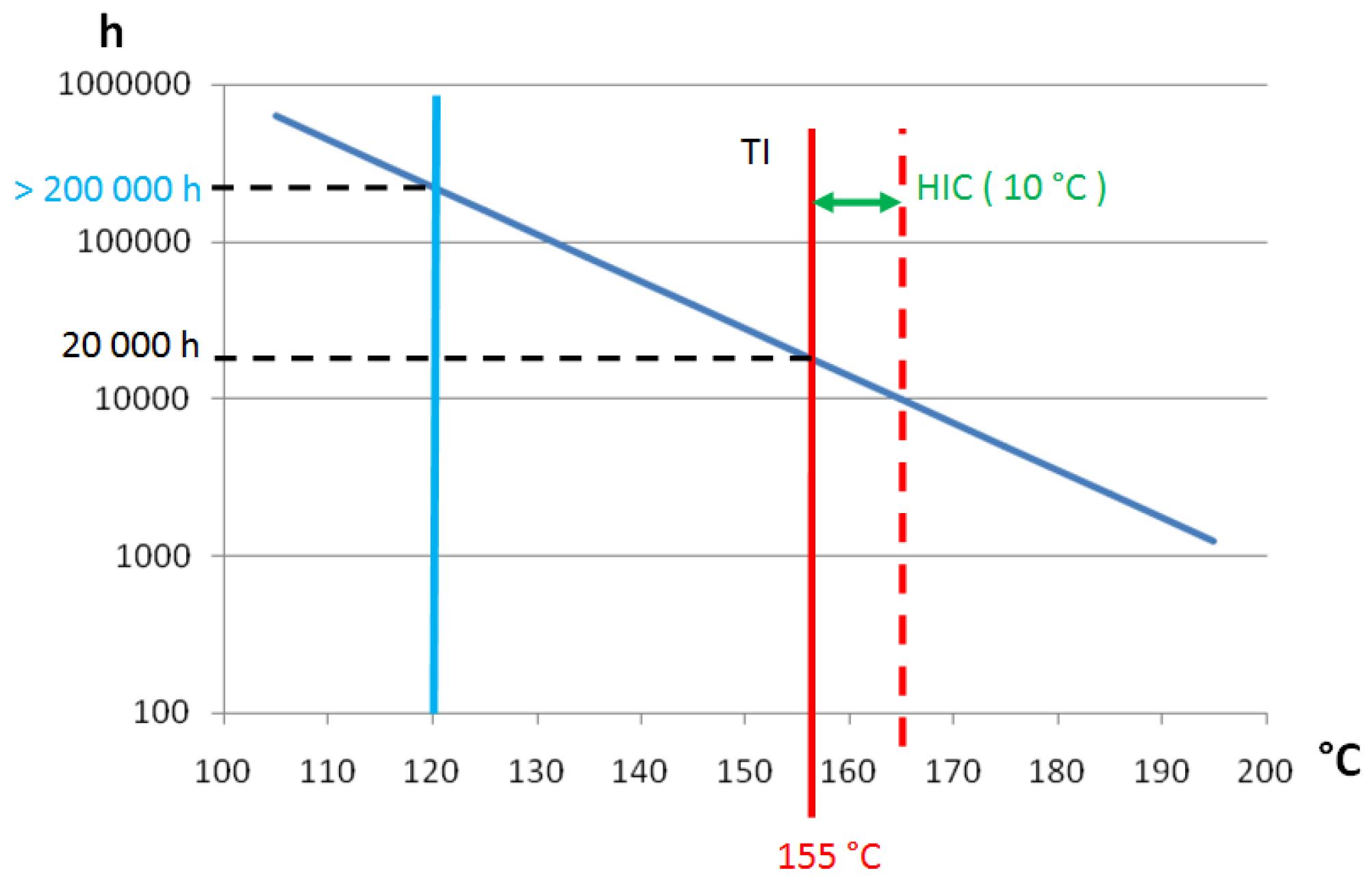
3.1. The Thermal Ageing in Front of Standards

Hence, thermal aging is a phenomenon which is understood and documented. About the resin, standards exist and are useful in determining the lifetime of a polymeric material used in electrical equipment. The UL and IEC standards give a relationship between the thermal aging of an insulation material and its lifespan. The expected lifetime of the insulation system is 20,000 h at a temperature which is the highest temperature allowed by the insulation class (Table 2). In the insulation system, the aging test is successful if the sample after accelerated aging, can withstand 50% of the initial voltage breakdown. In the event of a breakdown, a puncture appears in the insulation wall.
The aging of the resin is linked to the molecular behavior. During the manufacturing process, the molecules are highly reactive and the epoxide groups act with polyamide, organic acid or acid anhydride to produce a cross linked thermosetting solid resin [14]. In these materials, two types of links exist. The first is a strong primary bond (Covalent); the second is a weak bond (Van der Waals). Aging is a local change in the structure of the links. Primary bonds (Covalent) are broken and only weak bonds remain. Chain splits produce free radicals that can trigger other chain reactions. Such degradation accelerates with an increase in temperature. It is usually assumed that the rate of this degradation has the empirical Arrhenius form [15]. The main feature of this formulation is its exponential form (1). A small increase or decrease in temperature has a great impact on the lifetime. For example, it is usual to say that lifespan (L) is divided by 2 if the temperature only increases by about 10 °C.
L = A   e B / T
here L is thermal endurance time in hours; T is the temperature in K; A and B are constants dependent on environmental conditions.
Equation (1) is mainly related to one material and not to the insulation system. Nevertheless, it is recognized that the lifespan of the insulation wall will follow the form of its weakest component. Unfortunately, the unique way to determine the parameters presented in Equation (1) is in using test benches and these test benches must be done with real coils using the insulation system to be evaluated. It is not permitted to mix several manufacturing processes because these also have a great influence on aging. As the standard suggests an expected lifespan of 20,000 h, it is not realistic to run tests which will last more than two years. The standards anticipate this drawback and suggest accelerated aging tests, obtained by increasing the temperature.
First of all, the end-of-life criteria must be determined. About the insulations that are used in high power electrical machines, the criterion is the electrical breakdown: Ubreakdown. Such a parameter is measured on coils that have no aging. After being submitted to the Maximum allowed temperature for 20,000 h, the specimens must withstand 50% of Ubreakdown without damage. It is necessary to determine the thermal steps and the sequences of aging. For example, for an insulation system that should withstand a temperature of class F (155 °C). Standard IEC shows the following experimental sequences for the test bench (Table 3).
Within this test and after applying the end-of-life criteria, one curve can be drawn using the recommendations. This is the thermal endurance graph (Figure 5). Looking at this graph, three important values are written. The first one is TI (Temperature Index) here at 155 °C (Class F). The second one is HIC (Halving interval) here 10 °C, and the last one is the lifespan: 20,000 h. HIC = 10 °C, means that insulation system can withstand a temperature of 165 °C (155 °C + HIC) during 10,000 h. Hence, in limiting the operating temperature of a machine using class F insulation to 120 °C, the thermal lifespan will be greater than 200,000 h (25 years of continuous duty). The usual commercial argument is therefore demonstrated. Class F (155 °C) insulation and class B thermal stress (120 °C), lifespan: 200,000 h.
Such a result is not fully satisfactory because it does not take into account the environment of the machine during its expected lifetime. Any change can have a significant impact on the lifespan. Even though G. Stone in 2004 emphasized that over sizing the insulation wall was often used in machines to prevent premature failure [16], he had to conclude several years later that the competition in the cost reduction does not provide a positive result about the lifespan enhancement [3]. During 20 years, it has to be noticed that machines have an increase greater than 50 % in power density. This increase is also linked to a decrease in insulation thickness. Such a situation heralds suitable conditions for unexpected ageing under voltage stresses. Hence, some manufacturers built new machines with an insulation system having higher level of partial discharges in the insulation wall [17]. In introducing one improvement, in one part of the machine or in increasing the rated characteristics, all the other parts have to sustain the new operating conditions. When such an upgrade is observed on real machines, it is usual to have to deal with new problems in parts of machines which have never been under investigation. Improvements have initiated new conditions of use. Standards will not provide any help as they are written on passed experiments or return of experience. In a few pages, the Section 4 will give a short description of the history of one insulation system. It will be explained that improvements are not always improvements and industrial researches can lead to potential evolutions.

3.2. Ageing Parameter Other Than Thermal Ageing in Front of Standards

The thermal aging is documented, but it is not the unique source of stress. The relationships between the other constraints and the endurance time are similar. This remains an exponential relationship. This is the case of the voltage aging which is written in Equation (2). The voltage endurance test is based on IEC or IEEE standards. It can be used to compare two insulation systems in the same voltage endurance [18]. A material having a higher dielectric breakdown will have a longer lifetime. Such a property will be seen in “c” and “n” parameters (c increases or n decreases). An immediate application of this Equation (3) is to evaluate the lifetime of an insulation system using a power supply that induces a monitored overvoltage. The test duration decreases.
L = c   E n
where L is voltage endurance time in hours; E is voltage; c and n are constants which dependent on other environmental conditions.
L 1 L 2 = ( E 1 E 2 ) n
where L1 and L2 are the lifespan at the voltage E1 and E2.
Frequency also has a similar impact. It is presented in Equation (4). Such equations take a great importance when observing the accelerated ageing. It can be done with an increase of the frequency or an increase of the voltage [19].
L 1 = L 2   .   f 2 f 1
where L1 and L2 are the lifespan at the frequencies f1 and f2.
As a conclusion, the influence of many parameters on the lifespan is quantified. Nevertheless, there are no absolute results. Comparison with other insulation system is the key of the lifespan assessment. The standards provide only a guidebook on methodology. Hence, the standards have achieved their goal of providing a possible comparison between insulation materials. However, the standards do not provide any indication about the combination of constraints. Moreover, many stresses are out of the scope: mechanical stress, moisture, starting conditions, etc. Manufacturers are aware of these limits and believe that existing standards need to be improved. This is why they continually do researches about aging phenomena. Sometimes such improvements are significant and lead to standards revisions. Therefore, in the next section, a study case from Fuji-Electric history will show the incidence of manufacturers on standards.

4. Standards Evolutions and Experimental Aspects

During the standard ageing test, the coils are not powered and are not submitted to mechanical stresses. Moreover, the standards suggest that any added mechanical stress or electrical stress, should not introduce any significant additional aging during the thermal aging test. This means that such stresses cannot modify the ageing test. They can only be considered as diagnostic factors. Designing an insulation system using only Figure 5 will provide unrealistic information about the lifespan of the motor in operation. That is why manufacturers use additional tests and diagnostics to evaluate the lifetime of their new insulation process. This is especially true when new elements or materials are added. For example, in 1992, the Electric Power Research Institute (EPRI) released a report on the lifespan assessment. In this report, several insulation systems were observed. It begins with the old micafolium or asphalt-mica insulation systems, and it ends with the recent epoxy-mica or polyester-mica insulation systems. Within the EPRI analysis, although epoxy or polyester resin provides a great improvement in insulation, they also introduce an issue in the acceptance criteria. How can one provide insulation quality insurance when using new materials? Such an evolution will be initiated by the manufacturers and their proprietary tests. Many manufacturers have a history full of events in which twists and turns are usual. As the aim is not to write the whole history, only one manufacturer is used as an example.

4.1. Standards Evolution and Manufacturing Progress in Insulation Knowledge, a Historical Example

In 1959, Fuji-Electric Company published an article about their new insulation system which uses epoxy resin [14]. In this article, Fuji compares the properties of Shellac/mica, Polyester/mica and their proprietary insulation system: epoxy-resin/glass (namely F-RESIN). A large number of parameters, such as flexural modulus, breakdown voltage, dissipation factor, weight change in submerged oil environment were examined. At that time, there were no standards for these aging or diagnoses. Fuji-Electric has done several thermal aging tests, a set about the mechanical properties and one another about the breakdown voltage. The duration used is short compared to actual duration indicated in the standards. Fuji-Electric does not exceed 500 h at 180 °C, which is less than the time indicated by IEC. Nevertheless, Fuji-Electric heralds some important aspects that are now in common use. In 1959, the corona discharges, outside the insulation wall, are in interest. The voltage level used to power machines is high enough to initiate an electrical ageing phenomenon, now known as partial discharges. Fuji-Electric has built one of the first corona pulses counter. In doing so, they attest that their new insulation system is not sensible to corona discharges. They infer that the result is related to their vacuum and high pressure impregnation system coupled to the excellent fluidity of F-RESIN. With this new process they thought that they had no void in the insulation wall. Moreover, they imagined that their solution could remain mica-free as they considered mica as a source of void. History shows that epoxy resin is not void-free; the mica-tape can be associated to epoxy-resin. The epoxy resin does not behave well under a long thermal ageing. The epoxy resin cannot be used alone. The main result from the Fuji-Electric experiments is the use of corona pulse counter. Such a device has become one usual apparatus often used by the manufacturers to evaluate the quality and degradation of insulation wall.
During the year 1972, the Fuji-Electric Company, publishes another article about the F-Class “Stabilastic”TM insulation system [20]. The mica tape and the epoxy resin are in regular use. The corona effect and partial discharges are monitored by the designers and new environmental conditions have been incorporated. One of them is the high switching surges, induced by the new vacuum switches. No standard or data are available to integrate this operating condition. The manufacturer develops a test bench. The coils are heated to the maximal temperature (155 °C) and a high voltage is applied at 500 Hz. In doing so, Fuji-Electric uses accelerated aging methods. By studying the results of the breakdown voltage after aging, Fuji-Electric concluded that F-Class “Stabilastic”TM insulation can withstand switching surges. The voltage aging tests were then developed. The coils are powered by several different voltages, low to high voltage, and time to reach the breakdown is recorded. Hence, using these results, it can be concluded that, up to the rated voltage, the expected lifetime of the machines will be over 100 years. Unfortunately, this test is done without additional stress but the manufacturer knows that he must do the same by including all of the stresses. Moisture is an issue and needs to be tested on the test benches that provide the lifespan of this insulation system confronted to possible moisture pollution. Fuji-Electric has performed a water immersion test on coils for a long time (80 h). Such a test has similarity with the test associated with IEEE 429. It should be noticed that such a test is only applied to new motors. Even though the insulation system successfully completes the water immersion test, the standards do not provide insurance for the rest of the lifetime. If the customer specifications concern the whole life of the machine, it should be a good idea to test the stator windings by water immersing at its end of lifetime or by doing the same test after its decommissioning.
During the year 1979, Fuji Electric was investigating on the mechanical properties and qualification of coils insulation [21]. The F-Resin has been used for 20 years and data from operating machines are now available. They show that reliability must take into account the number of starts. Its effect has been observed in machines used in the pumping up in power plants. The manufacturer has identified that insulation breakdowns are due to electro-magnetic forces and thermal stresses induced by motor starts. They mainly noticed the influence of the coil deformation on Δtan(δ) (Tip-Up). Such an effect is linked to the mechanical fracture of the insulation layer induced by large displacements of the strands. They may appear when the motor starts, if the end-windings are not properly-fixed. This behavior should be coupled with mechanical fatigue. Fuji Electric has linked the average stress that acts on the coils to the number of solicitation. Doing so, designers can determine the lifetime of the motor as soon as they know the number of starts. Another field of interest is the short-circuit situation. The strains induced by the short circuits could not be studied with the same method. The manufacturer has built an impact tester that replicates the short-circuit effect on a coil. They also studied the temperature distribution during steady state. Using a machine running at rated power, they observed that a high thermal stress is encountered in the insulation wall, precisely at the end of the core. Since this area was already concerned by high electrical field, it becomes a weak part of the winding. By increasing the length of the conductive tape outside the iron sheets stack; this will put away the high stressed area. Such an idea is summarized in Figure 6. Notice, that the length of the conductive layer also depends on the vicinity of the iron parts at ground potential. To prevent high electric fields between the end of the conductive layer and iron parts, this outside length must be adapted. Hence, by studying one mechanical effect, Fuji-Electric also discovers other issues and the last recommendation enhances a well used design rule.

4.2. Insulation Knowledge, Qualification and Acceptance Tests

It is sure that other study cases can be found by observing other machine manufacturers. ABB, General electric, Siemens, Mitsubishi Electric, Westinghouse, Toshiba, Hitachi, Alstom, etc. have contributed in the past and are still truly contributing to the development of the sector. We should not forget also the insulation manufacturers which provide the mica-tape and any raw materials used in insulation wall. Nevertheless, the latest studies, carried out by Fuji-Electric, have not been followed by a standard draft. Even if the mechanical stresses are present in actual standards, they are not included as parameters in aging but only as pre-diagnostic parameters associated with a short mechanical stresses cycle. In the UL standard, the coils samples are mounted on a vibration table and are exposed for 60 min to a sinusoidal vibration at a frequency around 60 Hz, with a constant acceleration of 14.7 ms–2. Such an environment is therefore far away from a real start or short circuit conditions of electric motors. The standards do not correspond to the real mechanical operating conditions of machines because the real operating conditions are very hard to quantify and the accelerated tests are not provided, otherwise the qualification can be performed by doing all the required engine starts. Each manufacturer has experienced several potential defaults in the design or testing of new machines or machine parts. Industrial companies have no obligation to broadcast these information’s as they are a part of their personal knowledge. Even though the vacuum pressure impregnation (VPI) is now a widespread process, each manufacturer has its own chemistry and its own winding design. They do all the technical tasks for their own benefit. This is why published articles by the manufacturers about the insulation system have similar interests: they introduce the enhancements of manufacturers, but do not reveal any know-how [22].
Another environmental aspect that must be taken into account is the humidity parameter and it concerns each manufacturer and also each customer. Water can be absorbed by the epoxy resin. Even if this water can be removed with drying, it has a negative impact on the molecular chains. In the same way as thermal aging, chain scissions occur and lead to a decrease in mechanical strength [23]. Water and moisture had not always been a danger for insulation. They became a parameter of aging when the main binder is epoxy resin or a water-sensitive material. For many years, the epoxy resin was assimilated to a water resistant material. Even if this behavior seems to be respected at the beginning of the material life, such a property will not be systematically verified at the end of lifespan and especially after 30 or 40 years. Looking at the epoxy resin under the macroscopic scale, it appears as a hard material having a regular and smooth surface; surface that should not trap the water or the moisture. This conclusion is contradicted by others users of epoxy resin: the shipbuilders. The shipyards prefer the epoxy resin rather than the polyester resin, the polyester resin is destroyed by osmosis and cannot accept any water contact. The epoxy resin does not accept any water contact, but not for the same reason. The epoxy resin is not watertight. Water can penetrate the epoxy by capillarity and can initiate damages in molecular chains. A decrease in the mechanical properties would not be so hazardous for the epoxy used in insulation systems, but the intrusion of moisture or water into the insulation wall will induce other effects. This process leads to insulation breakdowns by teeing. Looking at the standards, acceptance tests do not accept water intrusion into the insulation wall. They suggest drying the machine in case of moisture. No acceptance test can definitively qualify the insulation system in the presence of a moist environment or accept insulation degradation due to moisture during the expected lifetime. However, the monitoring of the insulation wall during servicing periods can detect this aggression.

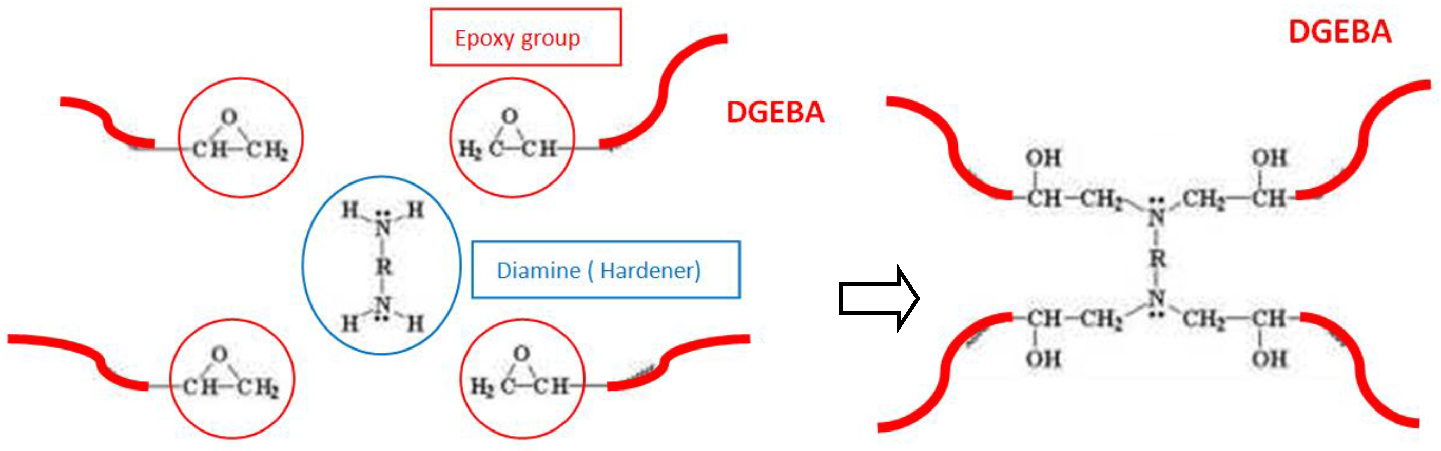
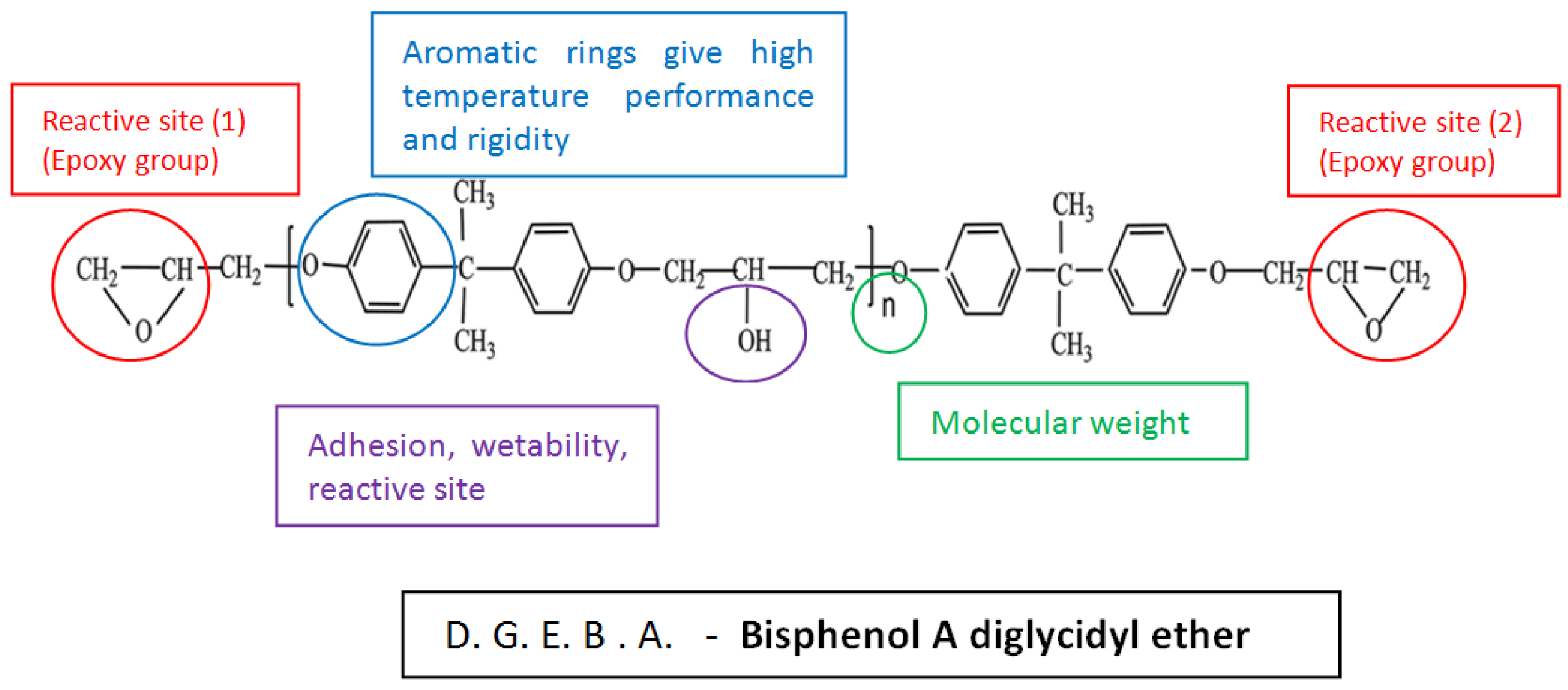
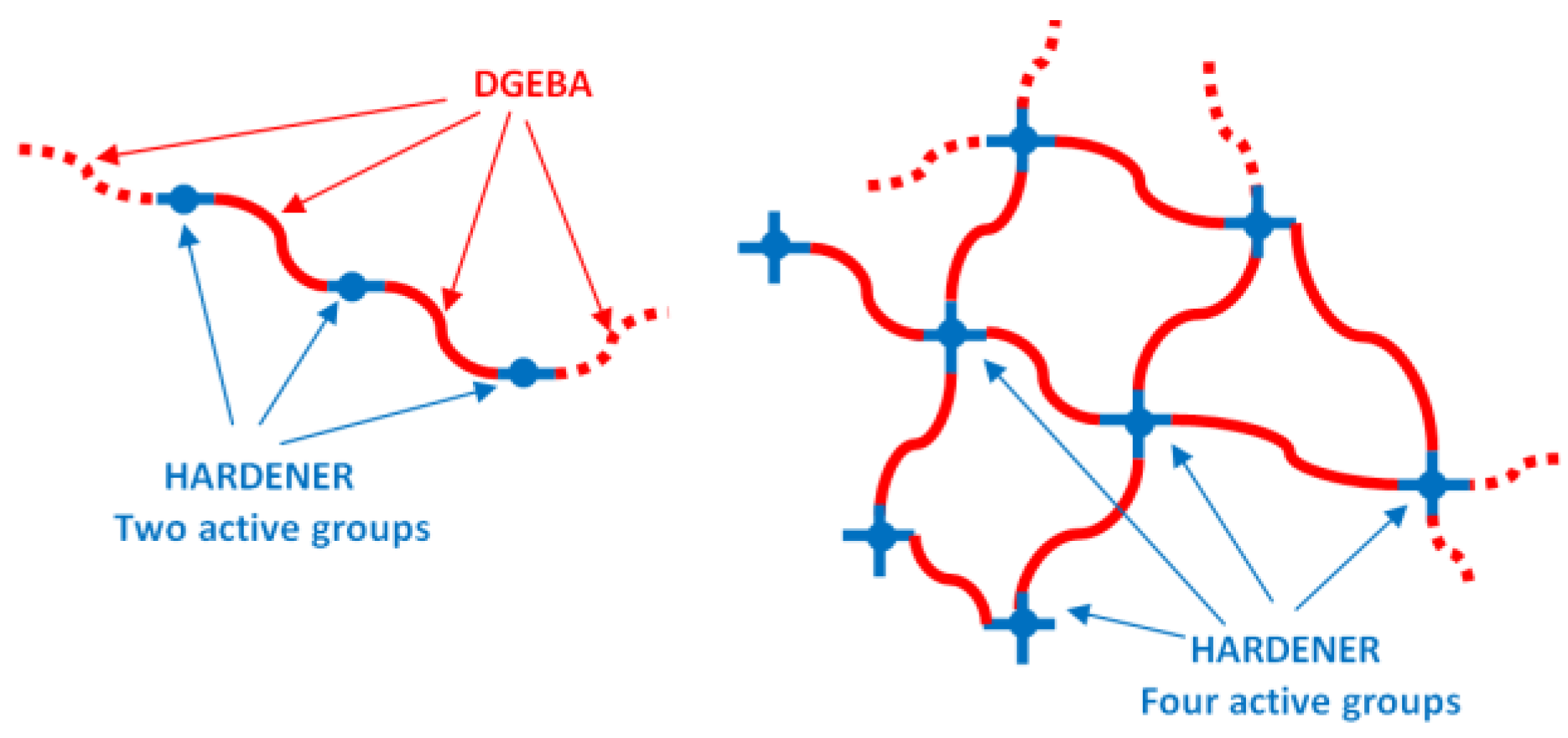
5. Bonding Material: the Epoxy Resin, the Weakest Part of the Insulation System

The epoxy resin has been used as a bonding material since the 20th century. The development of this synthetic resin was initiated in 1940. The polyester resin was also developed during the same period. Both were immediately considered as possible material for the insulation of electrical machines. In 1949, Westinghouse used mica-tape and polyester resin in its insulation system [24]. General-Electric follows them two years later. In 1958, G.E. has used the mica-tape and the epoxy resin for a new insulation system [25]. Both insulation systems exhibited better performances under high temperature conditions compared to older insulation systems (asphalt-mica). The polyester resin, even if it can provide a lowering of costs, does not tolerate water at high temperature [26]. Manufacturers of electrical machines were not the unique users of the epoxy resin. Thus, the maritime sector initiated studies about epoxy resin, water absorption and mechanical strength [27]. In this report, the authors studied the influence of curing and water absorption on the behavior of an amine-epoxy resin. Even if for an insulation system, the mechanical properties are not the determining elements. Designers need information on glass transition temperature and moisture absorption. The glass transition temperature (Tg) depends essentially on the curing temperature and also depends on the curing time. When a resin is completely cured, Tg is at its highest level. For the insulating system, the epoxy resin should be considered as fully cured. The authors observed that the glass transition temperature increases with curing even if the polymerization is reached. This means that a fully cured resin can evolve. Overheating may occur in the electrical machine when the operating temperature is high. The result will be a material that move away from equilibrium state and therefore will have more free volume and a greater propensity to absorb water.
The epoxy resin used in the insulation system is a mixture of elementary epoxy bases, hardener and catalyst. The epoxy resin can provide a lifespan that is able to reach 20 years. Extending the lifespan up to 30 or 40 years is not a goal easy to achieve without regular improvements. Therefore, the great improvement came from the manufacturing process. The VPI is a manufacturing process which appears in 1956. Dr. Meyer in collaboration with Westinghouse (Electric Company) applies this basic process for the complete filling of all the interstices of the insulated components. The first application that used the Impregnation system is based on Bitumen Bonded Mica Flake tape. The insulation coils were introduced in an autoclave, vacuum dried and then a high melting bitumen compound was added. When the stator is totally immerged in the compound, pressure is applied to assist the penetration. The filling is also enhanced by heating the bitumen compound to decrease its viscosity. At the end of the process, the unused bitumen compound is removed from the autoclave. Nowadays, the mica-glass tape and the epoxy resin were substituted for the benefit to this insulation system. The process has not radically changed. The mica tape is wrapped around the strand. The coils are inserted in the slot. The stator with the coils is introduced in the vacuum chamber. Vacuum is done and the epoxy resin is added. The epoxy resin must be liquid enough to fill the entire interstice. At the end, vacuum is removed and pressure is applied. Thereafter, the epoxy resin is cured at high temperature to obtain a rigid and indestructible insulation wall.
Enhancements are not always a customer or a manufacturer choice. During year 2014, a European patent was published under the exclusive trademark of ABB Research Ltd [28]. Their epoxy resin is designed to be volatile-free. It means that there was no volatile solvent. This single epoxy resin composition also has a prolonged pot life, which is suitable for the storage and a processing temperature within the range of 40 °C to 70 °C. As expected, this epoxy resin has good electrical properties as well as a low viscosity, at these temperatures, which is required in impregnation process. Note that enhancement of this insulation system is related to health and not related to industrial improvements (REACH recommendations in which styrene, used as solvent, is forbidden). In fact, Designers have to find an answer about two requirements which are usually contradictory: a long pot life and a short gel time. For electrical insulators using aromatic epoxy resin compounds, the material, frequently used, is the bisphenol A (DGEBA) (Figure 7).
Such a long molecular chain cannot ensure alone a hard material. The hardener is the main actor for this behavior. The hardener is an anchor point for the epoxy groups. If the hardener has only two reactive groups, it only provides a simple molecular chain without mechanical rigidity. To generate a tri-dimensional structure, the hardener must have a greater number of active sites (Figure 8).
When the reaction begins, the first reaction introduces a chain extension. That is a suitable behavior as it generates a material which is still soft and can creep into small voids. Thereafter, the cross linking reaction takes place and initiates a tri-dimensional structure. One of the most used hardeners is the polyamine having two or more primary amino groups –NH2 as anchor points. Such a hardener provides high cross linking (Figure 9).
Regarding machines having an extremely long lifespan, these chemical reactions are of great importance. First of all, the polymerization is never perfectly completed when the stator leaves the curing vessel. Even if several impregnations and curing are carried out, the resin lying between the layers will not be completely inert. This fact is found on machines in operation where an increase in insulation resistance is measured during the first months of operation. Indeed, the polymerization continues to be performed with the heat generated by the motor when it is running. Therefore, when the acceptance tests are performed in the factory, they are done on one insulation system which may not be in a stable state. That can be an issue for machines which are stored as spares.
About the manufacturing, even if the chemistry is well-understood [29] and even if reactions can be managed by catalytic systems, the first goal remains in a complete filling of the insulation system by removing all the bubbles. The resin must reach and fill all the internal layers, from the deepest strand insulation to the upper conductive layer. Such an impregnation is more difficult for high voltage machines; the number of layer in the insulation system is particularly important. Two contradictory goals must be achieved during this process; mica tapes should be firmly clamped on the copper conductor to ensure continuity of the insulation and must also be loose enough to allow the creeping of the epoxy resin. Such a requirement is always in the interest of manufacturers and patents such as US Patent 4,918,801 suggests routine tests to be performed on individual coils in order to verify the degree of resin filling between coils turns [30]. Thus, in this chapter, the authors have introduced a few elements related to the chemistry of polymers. These few lines remind that issues involved by organic chemistry will not be solved before a long time. Manufacturers must mitigate such issues by designing new manufacturing methods or in introducing, for the critical process steps, measurements which are able to verify the resin filling. The cited patent is linked to such measurement. Improvement in manufacturing process is well illustrated by the VPI. The next chapter will deepen this process and examine step by step the criticality arrangement of insulation wall.

6. The Defects and How to Find Them

The customers have at their disposal a large number of standardized tests that are able to provide information on the status of the insulation. However, these tests are not dedicated to machines with specifications. There is no test that is able to insure the lifetime of the machine. Machines with a long lifetime are machines which should reach the decommissioning date and be able to withstand all the events described in the specifications until the end of the last day. In the end, the best test is to check the machine at the end of its life! It is an unrealistic view, manufacturers will not accept this. Only tests that are following the factory release of the machine are acceptable. About the acceptance tests that may be suggested, three categories can be identified. First of all, the GO/NO-GO tests: they provide no information, but only a “passed” criterion. Next are tests that can be linked to numerical values with objective criteria. Such as Polarization Index that can be related to a status of the insulation wall. The last tests, such as Partial Discharges are not real criteria for the acceptance but are very important results for monitoring the insulation during its lifetime. In the acceptance test, partial discharges can be low and this does not necessarily mean that the lifespan is high. Degradations can further occur due to the future condition of environment. Many tests, like this one are tests that provide the initial status of the machine insulation. The requirements must be related to the state of the art and also related to data coming from monitored machines. When an outage occurs, it is easy to point out the parameter that is out of limits and do a reverse analysis. The customer can focus on his own know-how. Another solution is to introduce criteria into standardized measurements. The customer must integrate into his engineering team, machine designers that are able to translate the symptoms that can initiate defects into acceptance test criteria. Usual tests are summarized in the following table (Table 4). These acceptance tests may be associated to the contractual requirements but the acceptance tests used during insulation qualification cannot be cited in such a document (Table 5) since they take into account the insulation system and not the machine.
In selecting values for the criteria, the customer can improve the insulation system performances. The customer must have a good insight into this implication. The parameters associated with the criteria are highly dependent on the technology used by the supplier. Not all technologies are interchangeable and do not have the same areas of use. The VPI is suitable for large series and RR (Resin Rich) is suitable for high power machines such as alternators (several hundred MW). Lifespan is not based on standards listed in Table 4 but is related to standards listed on Table 5. It is obvious that manufacturers will do their best to qualify their insulation system using the best approved processes: return of experience, updated standards and improvements validated by industrial realizations. In the following sub-section, the authors will present these regular improvements.

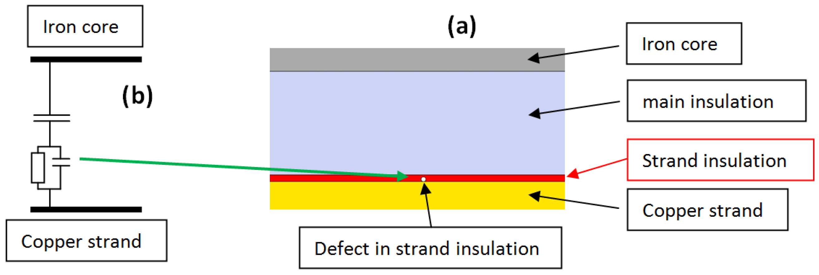
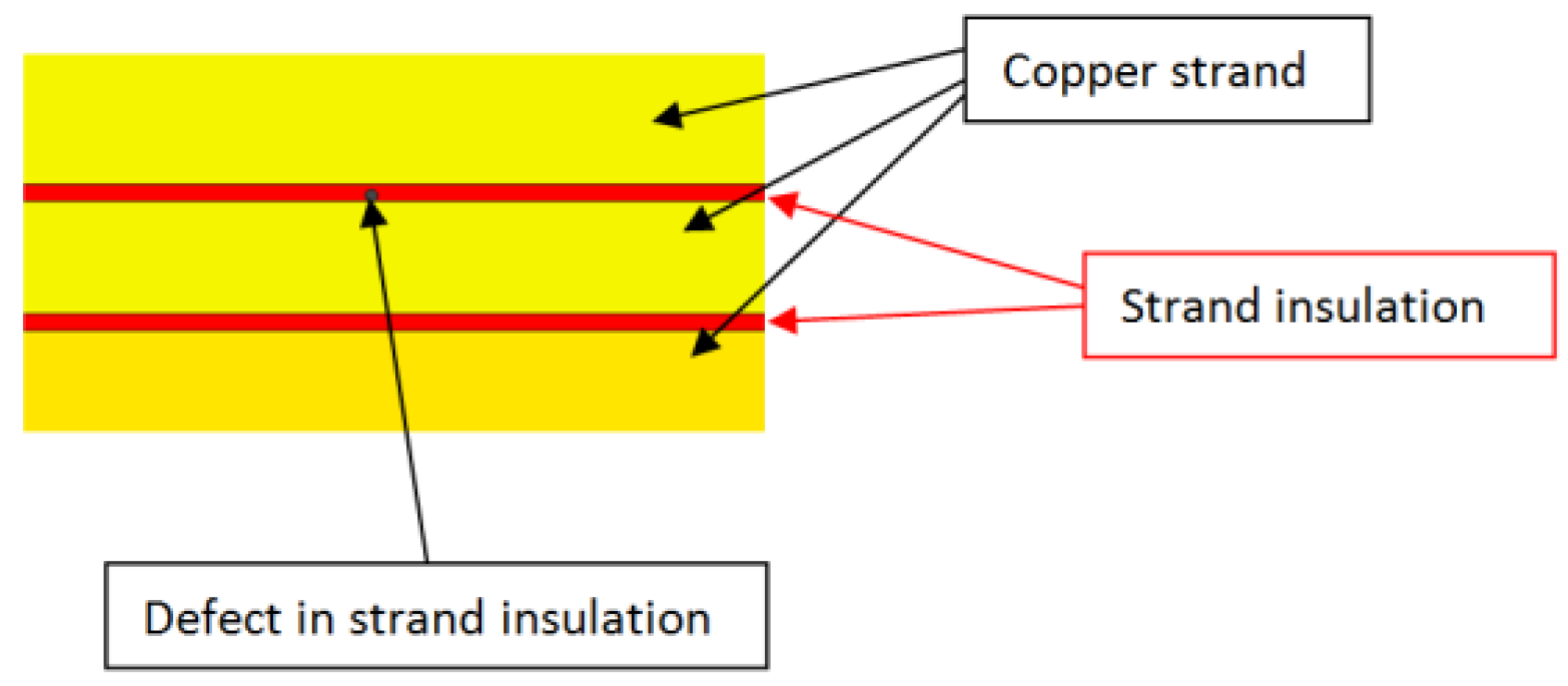
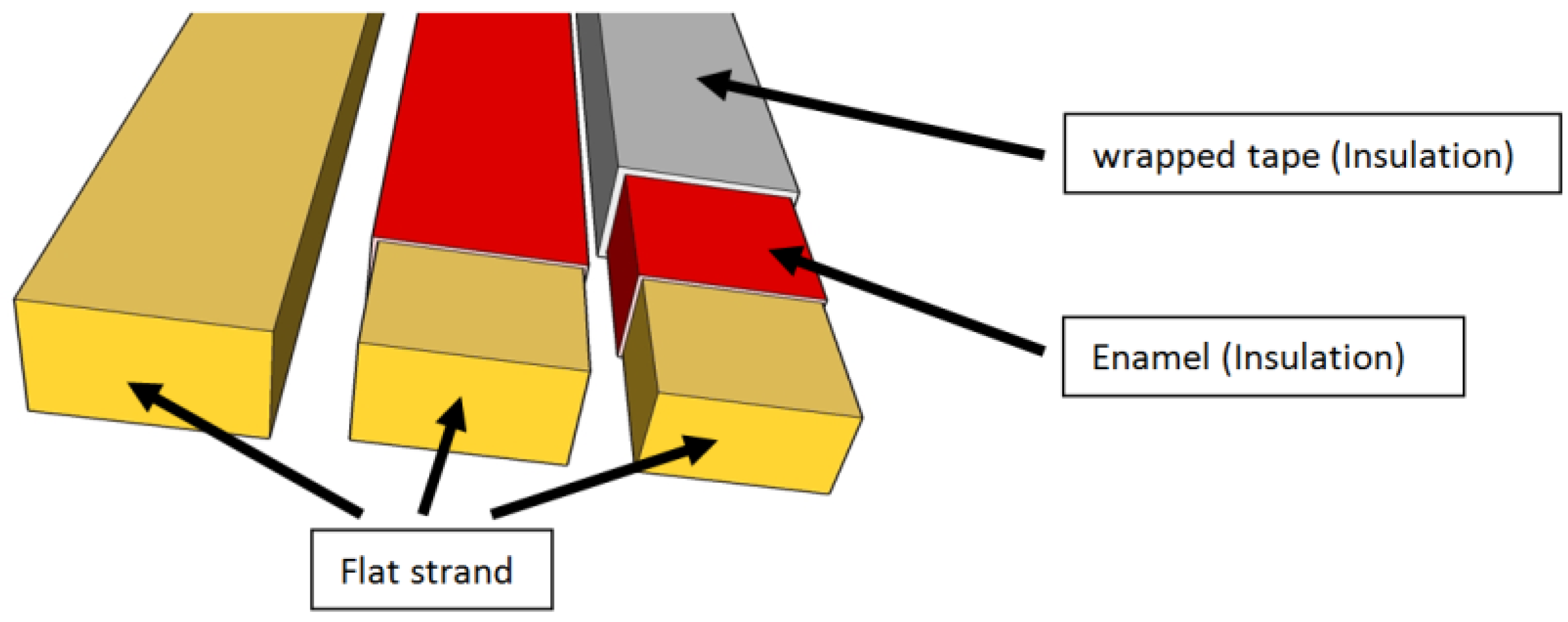
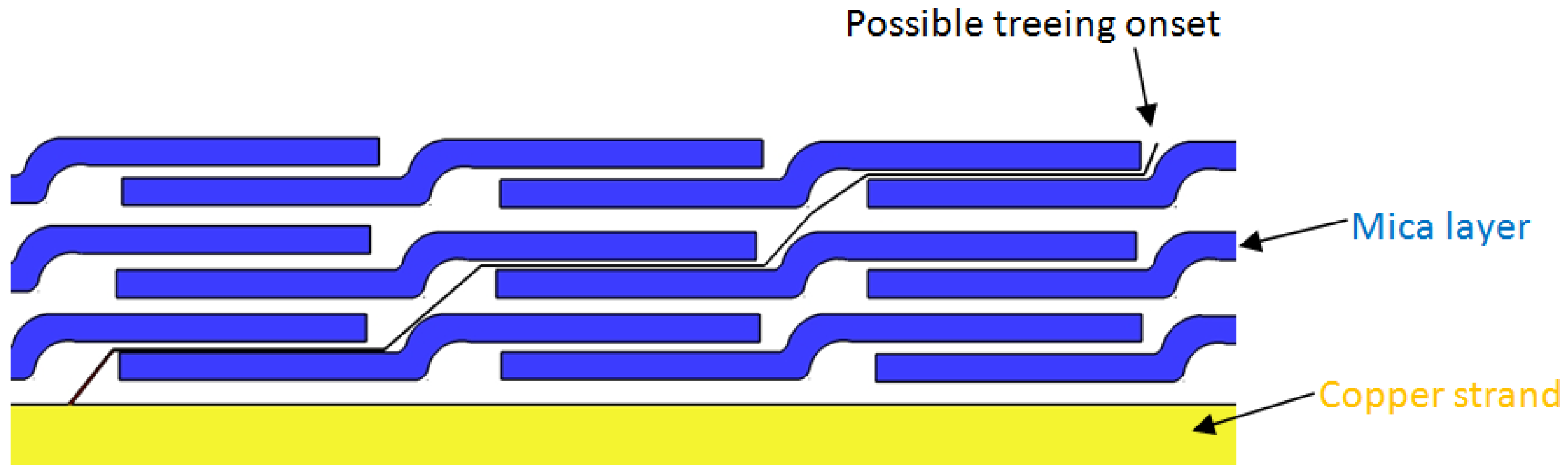
6.1. Strand Insulation, Criteria and Issue

The manufacturers which are using a conductor built with several strands in parallel must insulate each strand. This insulation layer has no voltage stress and can be achieved with a reasonable thickness. However, by forgetting its impact on the insulation wall, some misunderstanding can be done. Usually, the strands are not manufactured by the manufacturer of the motor and are supplied by external providers. Such providers sell the flat strands without any insulation to flat strands wrapped with one insulation tape and one enamel coating (Figure 10). Even if voltage between strands is low, designers should keep in mind that electrical stress can appear at the surface of the copper strands if the bonding is not well-done. Such a bonding does not have a great impact on low voltage machines, but this conclusion is not the same for high voltage machines. This layer is a sensitive layer because it is the deepest layer of the insulation system. The epoxy resin must penetrate from the surface of the insulation wall to this deepest area. If such a creepage is not satisfactory, this may initiate roots for partial discharges and can contaminate the insulation wall (Figure 11). That can be identified during partial discharge measurements. The PD activity related to this defect depends on the temperature. It decreases with temperature increase because the thermal expansion flattens the voids.
Another situation that can be encountered is a local rip between two strands which are in parallel (Figure 12). The lack of wire insulation leads to a short circuit between the strands and can be easily discovered during manufacturing. Before any soldering of strands, an insulation measurement between each strand can be done. If only two strands are not insulated, it means that a hole exists in the strand insulation.

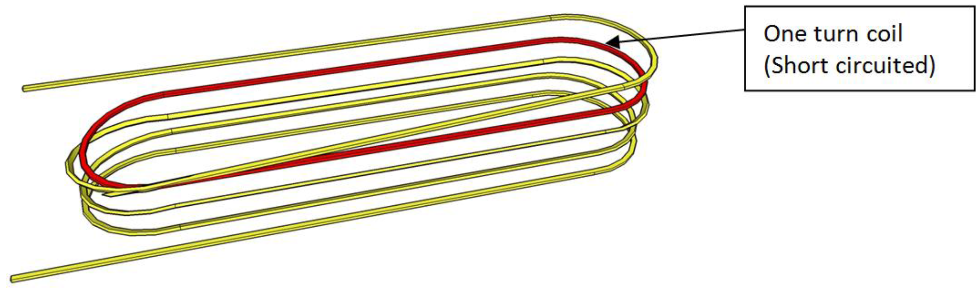
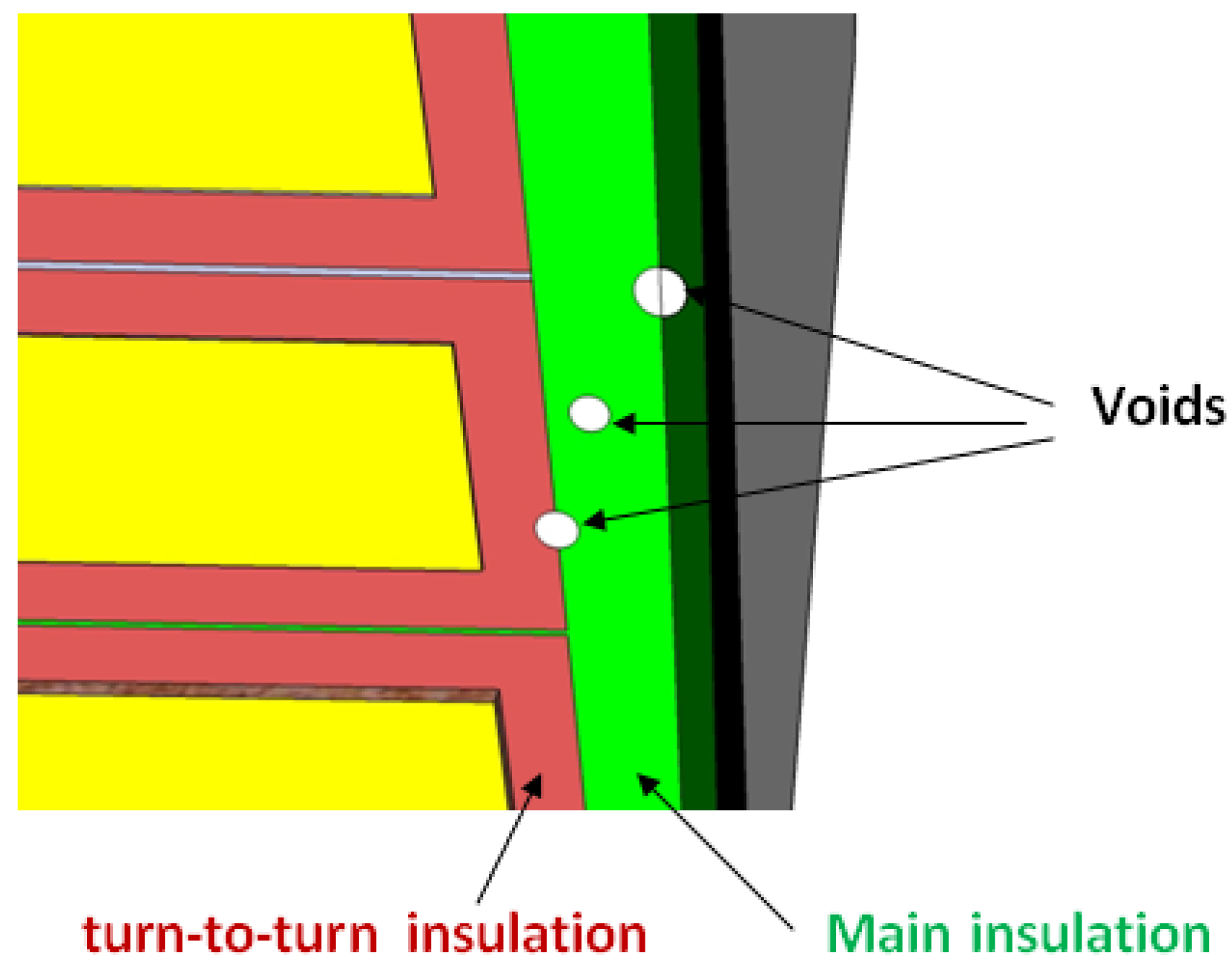
6.2. Turn Insulation, Criteria and Issue

Such insulation may have a similarity with the strand insulation, especially if there is only one strand that composes the turn. However, the goal is absolutely not the same. Even if the turn-insulation surrounds the strand, if it is alone or the strands if they are multiple; its role is to withstand the surge voltage mentioned in Section 2.2. Its thickness is related to the overvoltage. The calculation of the turn-insulation surge in the electrical machine is similar to the calculation used in power transformers [31,32]. Such electrical devices are more often subjected to the voltage surge than motors installed in closed areas equipped with surge capacitors. However, in the case of machines with a long lifetime, surge capacitors should be avoided due to their short lifetime. Therefore, it is mandatory to specify a lightning strike withstanding in requirements (mentioned in Section 2.2). Voltage surges and their modeling are taken into account for several decades [33,34]. Several publications invite users to assess stress by providing an analytical resolution and graphic resolutions that give in a short time enough data to conclude on the issue. Methods used in power transformers to mitigate electrical stresses induced by lightning are not applicable to motors manufacturing. In motors manufacturing, the consecutive turns must be geometrically continuous and for transformer manufacturing, consecutive turns can be interleaved [33,34].
Transformer engineering considers such a problem as a capacitor network with some lumped inductors (Figure 13). Doing so, the voltage distribution along the windings can be investigated [33,34]. It immediately appears that the first coils must withstand a high electrical stress. A large voltage gradient exists between the strands which are directly connected to the power line (Figure 14). Manufacturers have taken into account this event and found that this one is not as high as in transformer case. It remains that difference of potential is about several thousand Volt, whereas in continuous operation, this one is about ten volts. The solution usually employed is in increasing the thickness of the turn insulation.
However, such a voltage surge is not a regular event and the number of voltage surge during the life of the machine is limited. For this reason, the surge test defined by the IEC standard is not a usual test used in acceptance tests. It is not recommended to use this test during the upkeep periods because it will destroy a weak insulation.
One defect in turn-insulation usually provides a turn to turn fault. Two consecutive turns are short circuited (Figure 15). They act as a standalone coil with one turn that disturbs the magnetic flux circulation. A higher current is induced in this unwanted coil and increases the temperature of the winding. This increase shortens the lifespan of the windings. Such a defect can be detected if the line current is monitored. A small imbalance appears. It can also be discovered during regular servicing. The resistance of the circuit containing the turn-to-turn fault shows a decrease in its value. Such a decrease is low, around one percent or less (Temperature strongly affects the measurement). However, this topic is always in the interest of researchers and recent publications highlight this issue [35]. In this publication, which was published in 2013, the authors investigate methods that are able to detect the turn-to-turn faults. Each method has advantage and drawbacks. Drawbacks are not always considered as drawbacks compared to the domain of investigation. The off line/on line criteria, operator skill and relevant information are examined. Unfortunately, the impact of the machine lifespan is ignored. Power stations operators are aware that measuring devices have a short lifespan compared to the monitored motor. That becomes an unrealistic situation where the measuring system is out of order before the monitored device. As a result, methods based on less skilled operators which required high-end and automated measuring devices, installed within the machine are not adapted. Methods using external measurement systems which can be replaced by another acquisition system providing similar data are preferred. Such a choice implies high skill operators.

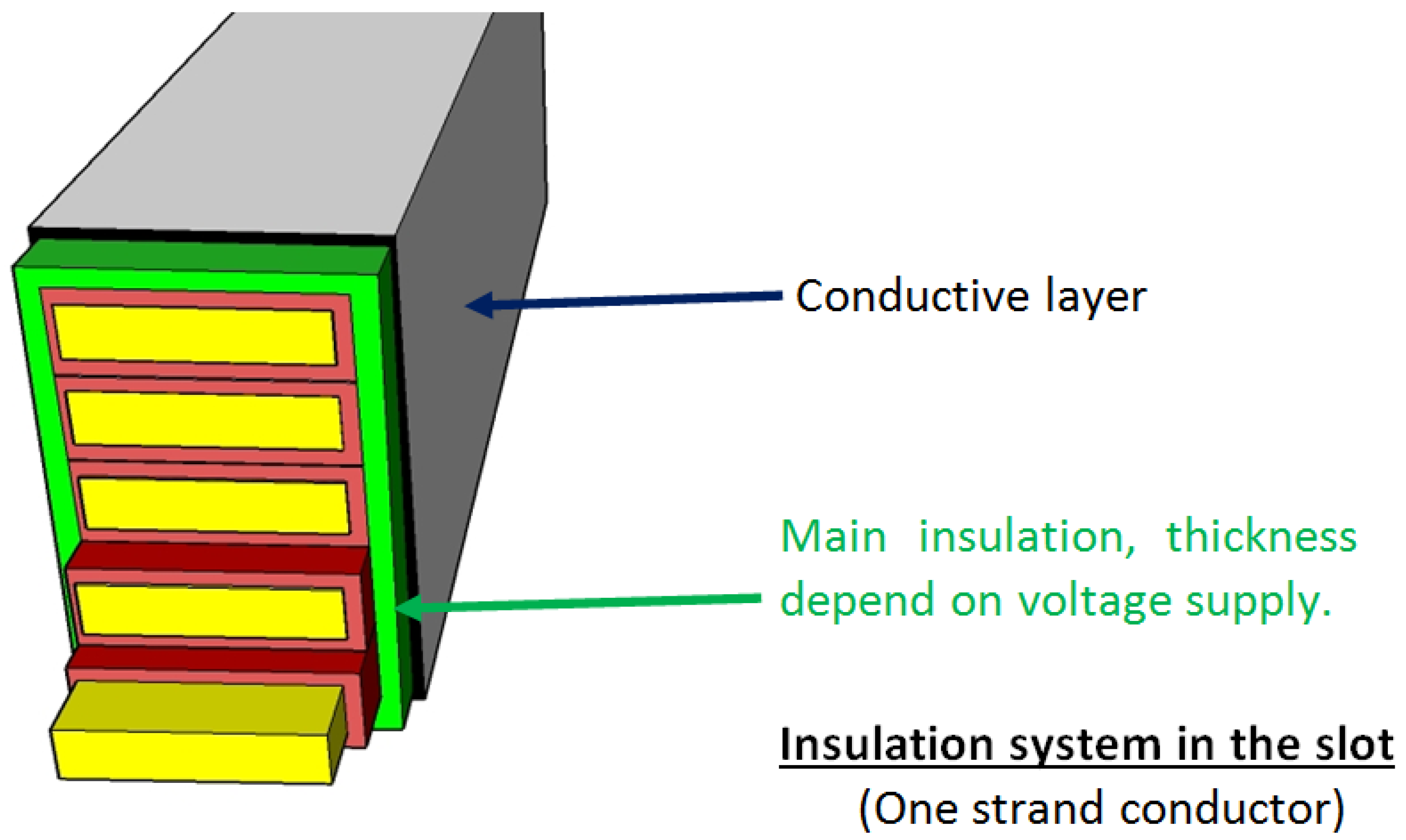
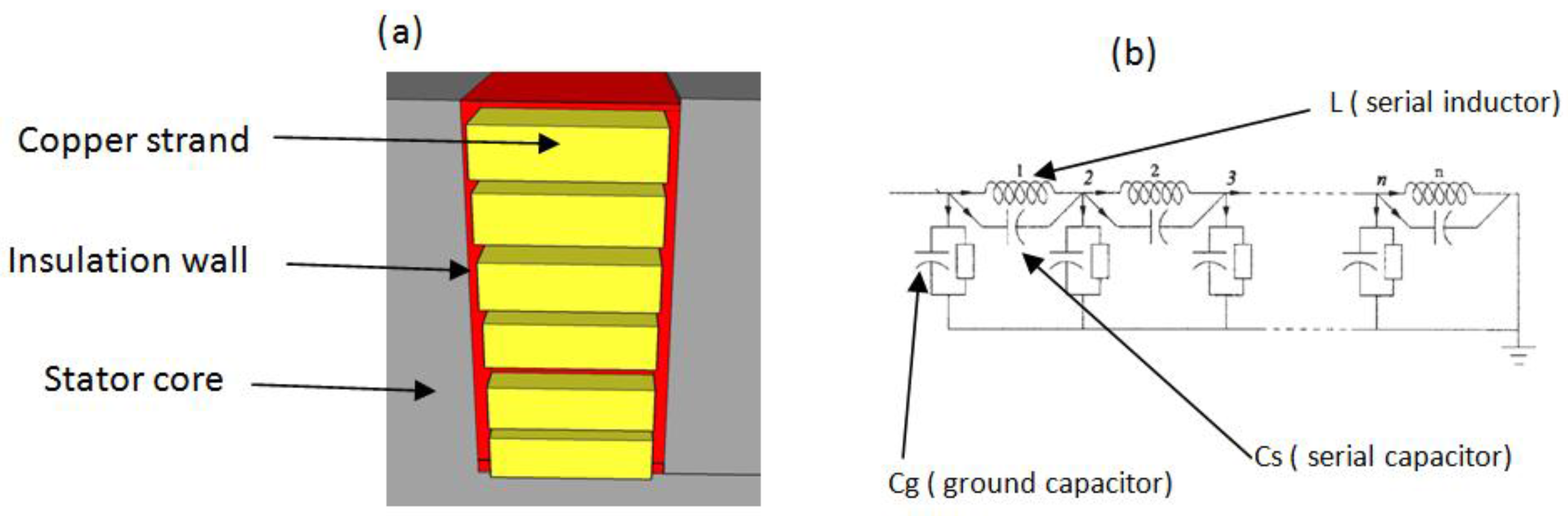
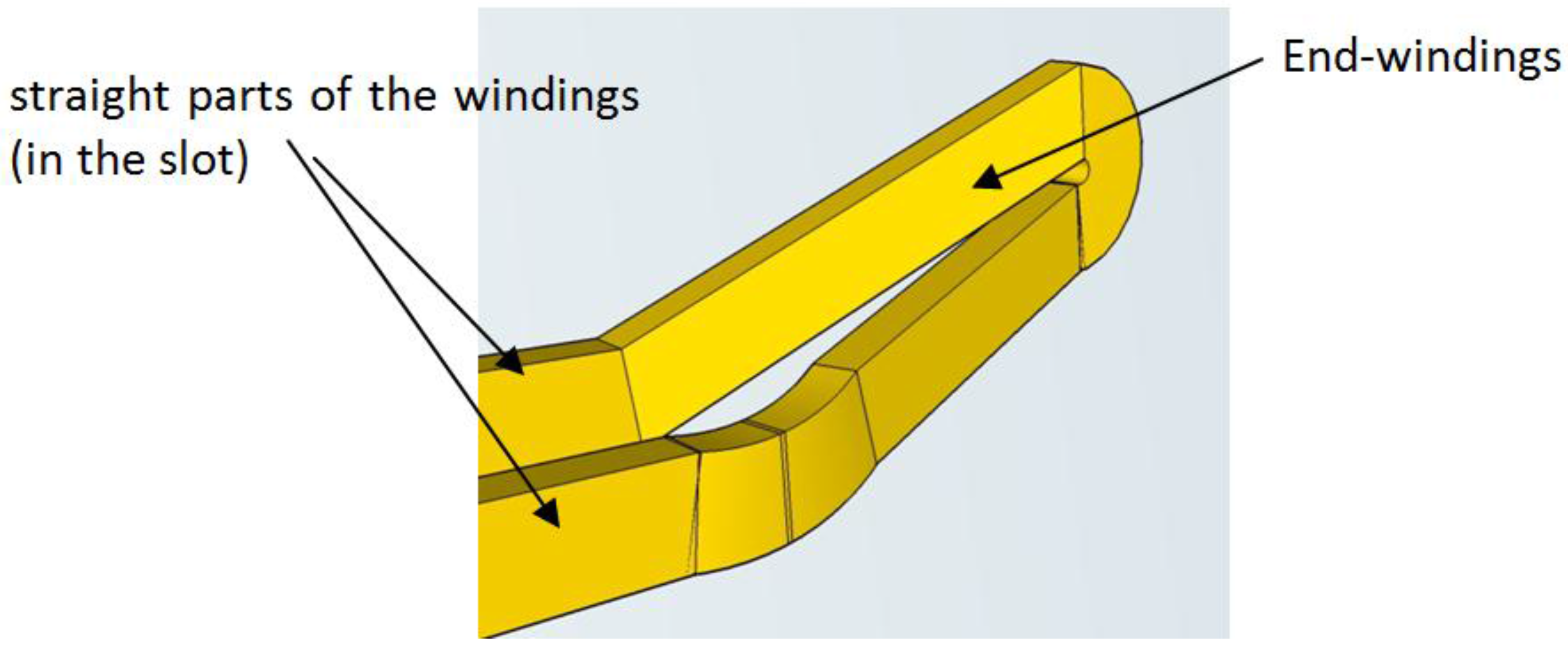
6.3. Main Insulation in the Slot, Criteria and Issues

Such insulation must be designed to withstand the main ageing stress which remains: the thermal ageing. The mica and glass tapes are highly dependent on the toughness of the epoxy resin. The first goal of the designer is to limit the development of any void which is the basic roots of electrical deterioration. Such a result strongly depends of the manufacturing process (Figure 16). During the first step of the VPI process, the stator core and the windings must be dried (Warmed around 50 °C and up to 110 °C, temperature depends on used materials). Water or moisture cannot be accepted in any part. Even if the stator must cool, a dry stator must not stay in an uncontrolled atmosphere. Such a situation can lead to moisture absorption. For the second step, the stator and its windings are introduced into a vacuum chamber. The chamber is closed and an extreme low pressure is achieved (the ideal situation is a real void). At the same time, the resin is prepared; epoxy resin must be free of dissolved gas. The epoxy resin is introduced into the vacuum chamber and a perfect filling of the windings is expected. To achieve such a result, a pressure is imposed when the stator is flooded with resin. The last step is curing that will accelerate the polymerization. Such a curing should be done using a chart showing the time sequences and temperatures. One VPI session is not enough to ensure a long lifespan for the insulation system. The surface of the insulation must be smooth to prevent corona discharges and unwanted voids which can remain in the surface should be removed. Two or three VPI sessions can be performed to increase the lifespan. Such an increase must be observed as a reduction of deterioration sources. Insulation wall ageing is also related to the voltage stresses. A slight decrease in this parameter has a positive influence. Two methods can be employed: a lower tightening in mica-tape can increase the insulation wall thickness or addition of layers to increase the insulation thickness. Both solutions have drawbacks. By adding layers, the resin may not creep within all the layers, especially into turn-to-turn insulations, which are the deepest layers. Unclamped insulation has no advantage as the number of mica layer is unchanged and a tape folding or tape slippage can occur during impregnation. In fact, the solution used remains a manufacturer’s choice related to its design and manufacturing process. One important aspect when several VPI sessions are performed: the curing process is repeated several times. The first resin coating will undergo several curing sessions; it must remain uncured at the end of the first session to avoid over-curing.
A void free insulation will not be easily achieved. Tighten the mica layers will not allow the flowing of the resin and loose layers will result in folds. One idea was suggested many years ago [36,37], the first results were presented in 2012 [38] and reaffirmed in 2014 [39]. Since free space is mandatory between the layers to allow the resin flowing. These free spaces can initiate treeing in the insulation wall. Treeing follows the mica layer (Figure 17), cannot puncture it and immediately bypasses it as soon as it reaches the boundary [40]. Therefore, an increase in treeing resistance of the resin can be achieved by adding SiO2 components. By using a variety of specially processed components, i.e., nanocomposites, the thermal conductibility of the insulation wall increases (up to 3 times). This leads to better thermal dissipation. The Tip-Up, which is a parameter of the good achievement of the VPI, also decrease. This value is less than 0.3 while in usual insulation wall it remains greater than 0.2 and less than 1. Voltage endurance tests show an improvement in electrical lifetime. This first step heralds a major improvement in the insulation system. The authors suggest the second step: the electrical, thermal and mechanical qualification tests of this new insulation system.
The origin of the treeing is located on both surfaces of the insulation wall (outside and inside). Any voids in the insulation will accelerate the development of such a defect. Inside the wall, too tighten layer is forbidden and outside, the treeing root is located on the latest layers of the insulation wall. A multiple sequence of VPI can smooth the surface and fill any unwanted voids. Moreover, a conductive layer is added to suppress corona discharges in the slot. In all case the ionization of the surrounding air induces Ozone. This gaseous material, even in low quantities, is highly reactive and reacts with the epoxy resin by breaking the cross-linked network.

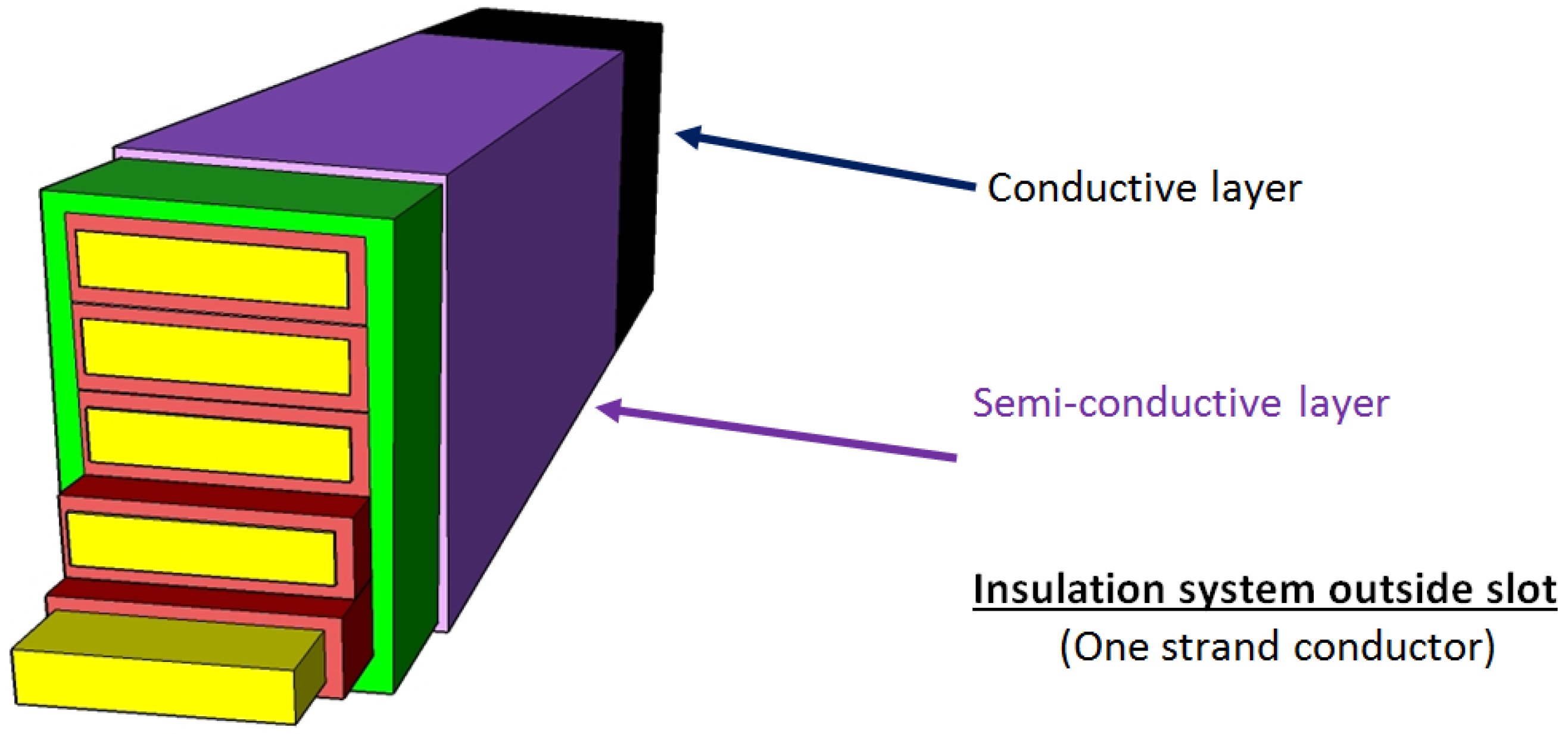
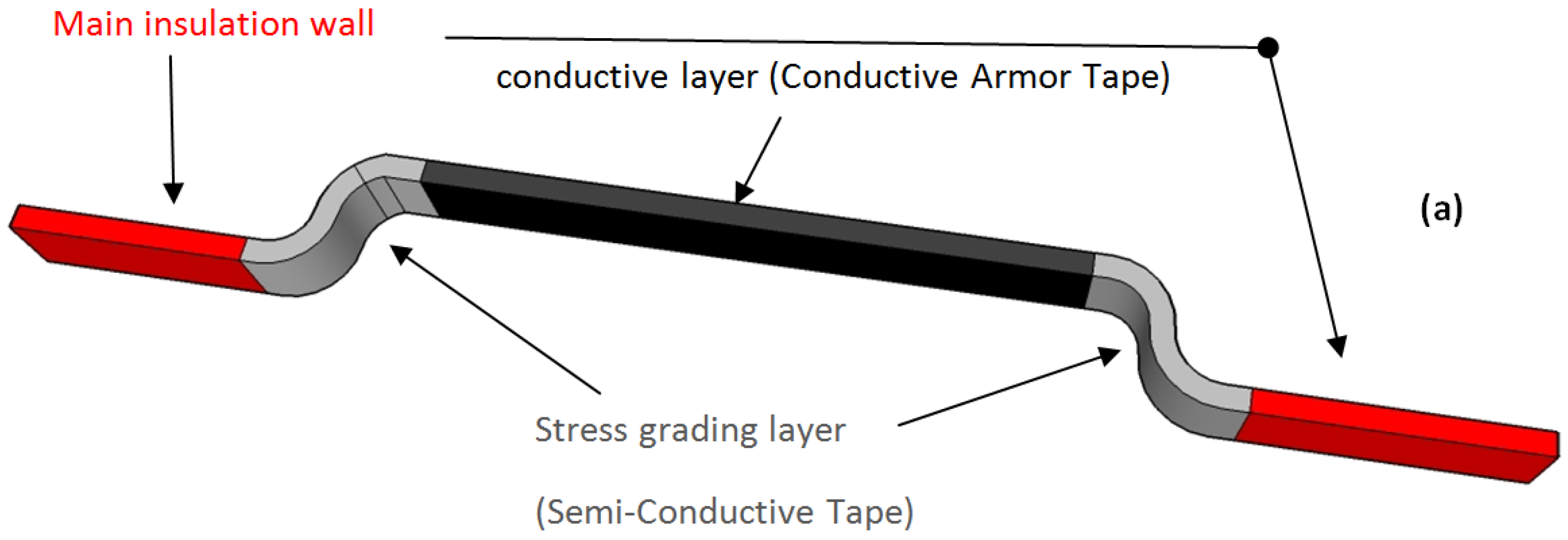
6.4. Main Insulation in the End Winding Area, Criteria and Issue

The machines with high mechanical power usually use form-wound coils. This implies a specific situation outside the stator core and in particular in the end windings areas. The strands are bent to fit geometrical requirements. The parts of the winding in the slot must follow a straight line and must not undergo any mechanical stress due to incorrect curvature. Hence, the application of an insulation tape is not easy. The geometrical shape of the end winding is complicated (Figure 18). The application of an insulation tape would not be as regular as it is shown in Figure 17. A handmade application is often required and provides degradations in the insulation wall quality. Even if the manufacturing price is cheaper, the automated process cannot provide, for these areas, a similar quality of application. The end windings are parts where many operations are already performed by hand: The soldering of the connection rings (One ring per phase), the soldering of the connection between consecutive coils and the soldering of the power cables. Applying insulating tape by hand is more realistic and allows a monitored increase in the thickness of the insulation wall. It does not imply an increase in the insulation strength; the folds during the mica-tape application cannot be avoided and the clamping of the tape on the coil is not regular. Thereafter, it is usual to find two additional layers or more in the end windings. Even if this winding part is not in the slot, the surface of the insulation wall has to be as smooth as possible to avoid corona discharges and ozone generation. This effect is raised in the end winding area since the two main elements concerned are adjacent coils (Figure 19). Such a defect can be monitored by observing light emission during a high potential test. This degradation scheme is often cited in articles concerning the diagnosis of machine outages. Such a drawback is a serious destructive phenomenon. It had to be taken into account. Patents on its mitigation can be found, for example, US 2007/0170804 A1 suggests the use of an additional mica-tape armor to mitigate such a destructive effect [41].
Manufacturers have spent many decades finding a solution to mitigate the voltage stresses associated with the interruption of the conductive armor tape outside the slot. Historically, the first solution consisted of using a coating containing silicon particles. In doing so, the electrical resistance of the upper layer is less important than an insulating layer and it evolves with electric field intensity. The electrical potential can be more evenly distributed and the magnitude of the electric field is mitigated everywhere. The use of such a solution namely stress-grading has a dramatic impact on the lifespan. During the first years of operation, the stress-grading layer behaves as expected, but the varnish-based coating, breaks up step by step and after a decade, this layer will be partially cracked. Such a defect is now solved by using stress-grading tapes. Nevertheless, Stress-grading is always in the interest of the researchers as its aging is not well-handled. Supply voltages increase steadily and manufacturers look after more adapted materials. Nowadays, electrical machines may be driven by variable speed drives and the shape of the applied voltage induces high levels of harmonics that age the stress-grading tape. Investigations on another type of material are done. The traditional SiC layer which is a resistive material will probably be replaced by capacitive layers.
The stress-grading layer impacts acceptance tests, especially when the criteria are based on the linearity behavior of the insulating wall. Manufacturers must integrate this issue. They must do tests that can take into account the non-linear effect of stress-grading. This can be done for half coils used in hydro-generators or large alternators. These coils are assembled on site; they can be tested separately during the acceptance tests. The Effect of the stress-grading is easily mitigated by drifting the leakage current associated with this layer. The guard electrodes drift the leakage current and insulation wall measurement is not polluted (Figure 20). Guard electrodes are not an answer for all cases. They cannot be used on machines using form-wound coils.
Nonlinear behaviors also influence other acceptance tests. The Tip-Up test may be impacted by the introduction of stress-grading tapes. In this test, the insulation resistance is measured at two different voltages. About some proprietary acceptance criteria, the first measurement is done at 0.25 Vn and the second measurement is done at Vn (Line-Ground). For these two situations, the power losses of the insulation system are measured. When the voltage is low, the stress-grading layers lead to no leakage current. By increasing the voltage to Vn, stress-grading leakages currents appear and may provide a higher level of power losses. Newly manufactured machines that use epoxy-mica insulation and SiC stress-grading often have a Tip-Up greater than 0.6 and less than 1 for the whole winding (This value is lower for a standalone coil). Therefore, customers should not indicate in their acceptance criteria a lower value for the Tip-Up. Fortunately, the standard that describes the measurement process also describe a favorable situation. In this standard, only one coil is powered. It means that the voltage between a powered coil and all the other coils is limited to the phase-to-neutral voltage. In operation, the voltage between two different coils can reach the phase-to-phase voltage.
A long lifespan involves regular stress-grading improvements. Stress-grading varnish is no longer used in high power motors. Tapes are preferred. Many technologies exist in stress-grading tape. There are the Resistive Stress-Grading technology (RSG) and the Capacitive Stress-Grading technology (CSG). The CSG is not suitable for electrical machines. About RSG, two types of materials can be used. Silicon carbide (SiC) or Zinc oxide-Varistor (ZnO) can be employed [42,43]. SiC tapes are in use in electrical machines, whereas ZnO is used in insulators [44]. Stress-grading tapes have characteristics that evolve with the frequency and the strength of the electrical field. Its resistivity can be expressed using Equation (5) [45]. The length and thickness of the stress-grading can be chosen with numerical simulations. Equilibrium must be done between the levels of electrical losses, the highest values of electric fields and the leakage currents [46].
ρ = ρ 0 ( f ) e k E
where E is electric field strength; f is frequency; ρ and ρ0 are material resistivity.
Modeling using discrete elements has advantages. The elementary parts of the stress-grading layer may have monitored properties. Unfortunately, the geometry of the stress-grading, and in particular its thickness, leads to programming problems using the finite elements method [47,48]. Practically, designers want to know the highest value of the electrical field, the thermal hot spot location, the expected leakage current. Any excess of these values will have a negative impact on aging. 3D simulations, which include all coils, are not realistic. The solving times will be too high. Some authors suggest simplifications in solving [47]. Thereafter, 2D simulations can provide enough information to study the stress-grading layer effect. Figure 21 and Figure 22 show two situations that will be used as working cases. In the first case (Figure 21a and Figure 22a), there is no stress-grading and the 2D axisymmetric simulation indicates a high level of electrical field at the end of the conductive armor tape. In the second case (Figure 21b and Figure 22b), a conductive layer with constant conductivity is added. The hot spot in electrical filed has disappeared. Nowadays, most of simulations only take into account one strand [49].
Such a result has already been introduced in Chapter 2. The mitigation of the electrical field must also be performed along the tangential axis. Corona discharges along such a surface can generate Ozone. In Figure 23, two simulations are performed. The first one is done with a stress-grading layer having a constant resistivity. The second one is done without stress-grading. It appears that stress-grading mitigates the tangential electrical field to a lower value. Researchers also studied the thermal effect on the SiC stress-grading. They found an incredible increase in leakage current. A factor 12 was measured [50]. Therefore, even if stress-grading has a positive impact in the local mitigation of electrical field, investigations must be done by monitoring its own aging. Destruction of a stress-grading layer can lead to a failure in a short time. Unfortunately, such a problem must be coupled with thermal problem and multiphysic simulations are expected [51]. The manufacturers include in their experimental studies the stress-grading tape [52].
As a conclusion, in this chapter, the authors go deeper in the current standards and highlight the fact that such standards are not able to close the debate about the acceptance tests for qualifying the machines with long lifespan. Nevertheless, standards help designers and customers by providing them methods and trends in measurements. Step by step, authors have taken each element constituting the insulation wall and have investigated about the issues and the possible answers. It appears that the number of issues is increasing; methods to solve them are more and more complex. The finite elements simulations take more and more time and are not able to take into account all the parameter. Fundamental issues do not change; excesses in electrical fields, abnormal temperatures, and unusual mechanical vibrations are always topics for researchers. Thereafter, designers have the difficult task to gather all the data and have to decide which road map would be followed for one enhancement within the insulation system Designers are not alone and manufacturers who provide high lifespan machines have background knowledge and a long experimental past. Even if such a fact cannot be examined in deep for each manufacturer as they want to keep their skill, it remains that open studies will bring enough data to understand the main issues: the mitigation of thermal, electrical and mechanical stresses.

7. Knowledge Base and its Influence on Insulation Process

The evolutions of the insulation wall are regularly presented by researchers. The articles cited show that innovations which lead to a real new insulation system take a long time to be integrated. In 1959, Fuji-Electric thought that the use of Mica could be avoided. The following decades will change this idea. In 2002, the nanotechnology with its Si02 particles suggests an improvement in the performances. Nowadays, this improvement is not regularly used and has not led to a new insulation system. The insulation system evolutions are also related to the evolution of the manufacturing process. Patents can be found about insulation systems that have not been developed. Although calculations or simulations can provide important information on the degradation factors that act on the insulation system, its behavior during operation remains the first evaluation criterion. EPRI provides several studies with exhaustive analysis [53,54]. It is certain that lifespan is a multifactor degradation. In 1978, one article begins with these words: Insulation Aging a Historical and Critical Review [55]. In 2014, such multifactor aging is still being studied [56]. Combining ageing factors remains a vast domain as the combining method has a great influence on the lifespan assessment [55]. Nevertheless, even if standards exist, they are out of the scope. For example, IEC 62101 has gathered the electrical and the thermal stresses but is focused on voltage supply less than 1000 V.

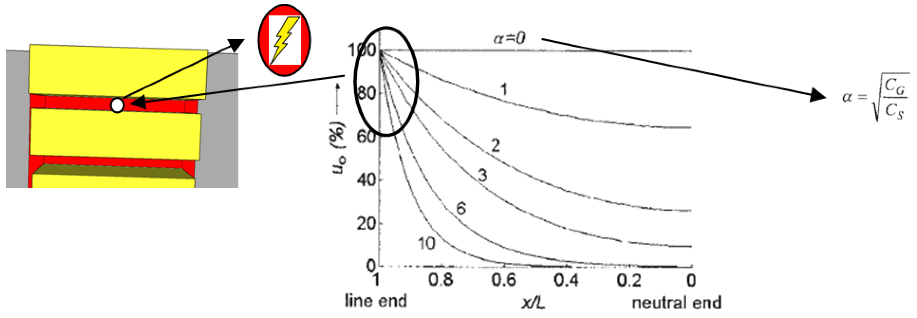
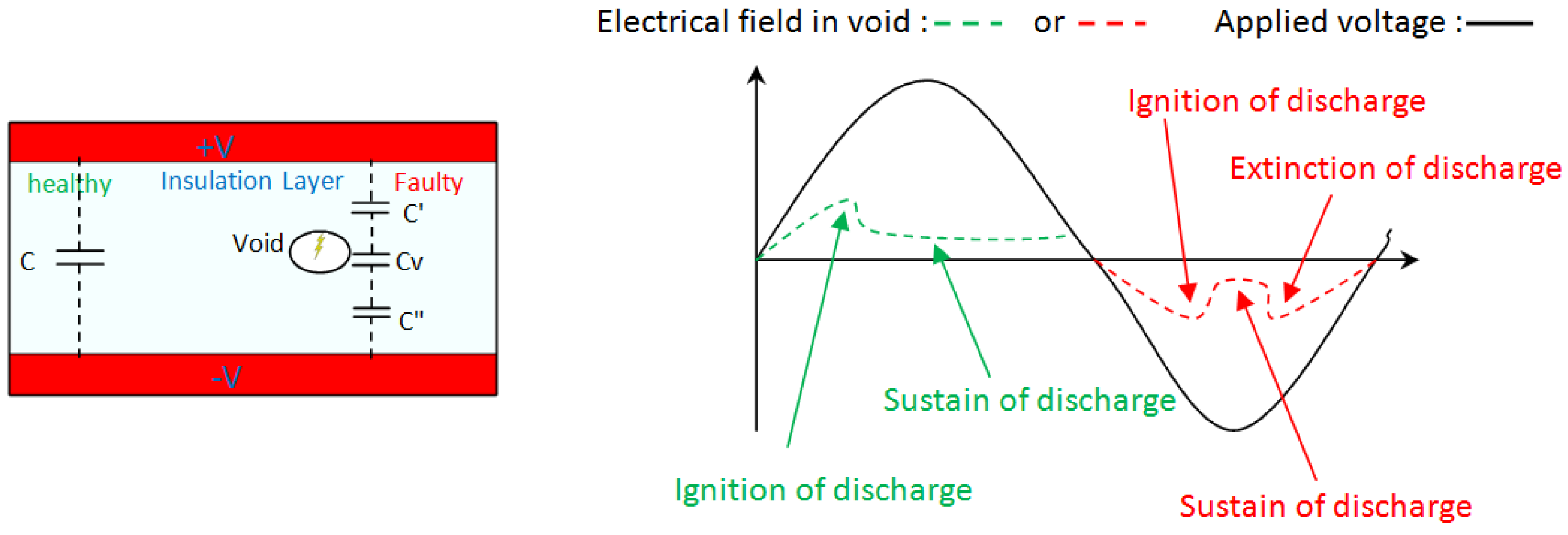
7.1. Partial Discharges Mechanism

A bubble free insulation is an ideal insulation system that will never exist. Bubbles are dangerous; they initiate degradations of the epoxy resin [57]. The bubbles in insulating materials can be created during the curing phase. It is impossible to remove completely them in the polymeric materials. The bubbles may have a diameter of a few microns. For example, such small bubbles are found in cross-linked polyethylene of cables insulation. By using VPI, remaining bubbles are assumed to be empty. Such voids have high breakdown voltage (10 to 1000 kV/mm). Unfortunately, bubbles are not real voids; they may contain gases which have lower permittivity and lower breakdown voltage. Smallest bubbles are the first bubbles that generate partial discharges (Figure 24).
The partial discharges are phenomena that are initiated during the last step of the manufacturing process. Small voids can be mitigated with an appropriate process. Doing the VPI with care can prevent the entrance of polluted gas. The phenomenon can be described using Figure 25. A sinusoidal voltage is applied to the two boundaries. Without void, insulation is a capacitor (C). When the voids are present, three capacitors appear the most important is: capacitor linked to the void (Cv). In this area, electrical field can overcome breakdown voltage. A leakage current may appear and can disappear after a decrease in the applied voltage (red curve) or be maintained during the positive part of applied voltage (green curve). The electrical discharge is detected outside the insulation wall by an apparatus and after calibration of the signal, the measurement of the energy expended during these phenomenon provides information on the insulation wall quality. For more than 50 years, companies have performed Partial Discharge Testing on electrical apparatus as part of predictive maintenance programs; skilled users can interpret the signals and point out which part of the insulation is subject to defect [52,58].
Even if the measurement of partial discharges concerns the number of discharges and the associated energy, the parameter used in acceptance tests only concerns the total energy associated to these discharges. At low voltage, only small bubbles are subject to partial discharges. At rated voltage, large bubbles light up and provide high level of partial discharges. Large bubbles are undesirable as they will provide an unacceptable level of partial discharges within a few years and will lead to a breakdown. However, the effects of large bubbles may be incorporated into acceptance criterion. Customers can overcome this issue by using the Tip-Up criterion. Tip-Up focus on the equivalent circuit, R + C, of the insulation wall (Figure 26). The resistance takes into account the losses which are essentially resistive losses. Partial discharges may increase resistive losses with their leakage currents. Since large voids will not be activated at 0.2 Un, the large voids effects will pollute the measurement performed at Un. Therefore, the insulation wall without large void has a low Tip-Up and an increase in Tip-Up may be induced by large voids (Figure 26) [59,60].
The partial discharges in bubbles are a mechanism which slowly degrades the epoxy resin. It means that a low level of partial discharge is a good indicator of a healthy insulation wall. One important phenomenon is the effect of the gas in the voids. For a perfect insulation system, there will be no gas in the voids. Such a requirement is not straightforward, especially in areas which are close to the surface where any cracks may break the sealing. Therefore, the phenomenon that must be taken into account is the behavior of a small bubble containing air. Such a work has initiated lots of publications and some of them provide enough ideas to initiate a discussion. The partial discharge mechanism has been fortunately studied using experimental validations. In 1993, a published thesis provides an explanation in the evolution of voids under electrical stress [61]. The author has investigated two study cases. In both case, bubbles are filled by gas. Even if studied bubbles are larger than bubbles present in a real insulation wall, voids with a height of about 30 µm are still representative. In one case, only nitrogen filled the void and in a second case nitrogen and a small amount of oxygen. In both case, the voltage stress is over the inception voltage, the first type of discharge that is observed is the streamer discharge type. The streamer discharge is a discharge which is characterized by a peak of energy with a short duration, about one nanosecond. The area affected by this discharge is limited to a small part of the bubble. It is during this step that an important evolution appears. An acid was produced during this step and spread on the surface of the bubble. That is mostly oxalic-acid. Such a product is important as it initiates the second step. After a short time of aging, less than 2 h, the author identifies a new behavior. The discharge process is now a slower process (such as Townsend discharge process). Even if this evolution is characterized by a lower peak of energy, its duration is greater and the phenomenon can affect the entire surface of the bubble. The acid created in the previous step lay on the surface on the bubble. It may be observed as powder or whitish gel and has a conductive nature. The last step is the pitting stage. During this step, a higher rate of discharges is observed as well as a localized attack around the crystallized acids. All this leads to the formation of pits. Pits will induce, in the future, the electrical treeing [61]. The transition from the first step and the second step may be interrupted. The absence of O2, CO, CO2 and H2O should inhibit any oxidation reaction. One solution to avoid such intrusion into the insulation wall is in doing 1 or 2 additional VPI sessions. In doing so, the voids close to the surface are perfectly sealed.

7.2. Mechanical Vibrations and Temperature Glass Transition

One alternating current in a wire produces alternating magnetic fields. When two wires are close to each other, the Laplace forces appear between these two wires at twice the frequency of the alternating current. Hence, as electrical machines use alternating currents at 50 Hz (60 Hz), any wire is undergoing an alternating force à 100 Hz (120 Hz). Even if such an alternating force is low in amplitude, it exists during all the lifetime and has to be taken into account in the design (Figure 27). It immediately appears that such a mechanical stress acts on the insulation system. The material, which will undergo such mechanical stress, is the epoxy-resin. The most important parameter about the epoxy-resin is the temperature of glass transition (Tg). When the temperature of the epoxy-resin is lower than Tg, the epoxy-resin is considered as a hard material. If the temperature is greater than Tg, the epoxy-resin acts as a soft material, and more precisely as a soft material which can absorb vibration. Even if the epoxy resin becomes a soft material, it keeps its shape. In increasing the temperature, the material can reach a flabby behavior, which is not desired. Hence, it is not easy to choose the state the epoxy-resin will have for rated conditions. Epoxy-resin must be hard, soft or within an intermediate state? Fortunately, one experiment will give the answer [62]. A test bench has used generator bars. The bars were submitted to low vibrations at 100 Hz and were also powered with a high voltage supply (32 kV). It appeared that the epoxy-resin within its hard state did not have a good behavior. The electrical breakdowns occur earlier when the temperature of the insulation system is lower than Tg.

7.3. Nanocomposites, An Answer to the Lifespan Extension?

In the previous chapter, many ideas have been introduced to increase the lifespan of the insulation system. The main improvement must be done for the epoxy resin which remains the weakest part of the insulation wall. Authors introduce one application of nanocomposites in order to decrease the treeing phenomena between layers in insulation system [36]. As mentioned, this innovation has not led to a usable insulation system and is still under evaluation. Their introduction into insulation system will have an impact in the evolution of acceptance criteria. This conclusion is provided by this recent review [63]. Authors have thoroughly examined the polymers properties and their evolution when nanocomposites are included. In particular, the behavior of filled epoxy-resin has been under investigation. First, the electrical breakdown voltage may increase by using suitable nanocomposites instead of microcomposites. The compounds are also more resistant to partial discharges and reduce the treeing possibility. However, the dielectric strength of the epoxy resin may be deteriorated in including too high-permittivity fillers [64]. Unfortunately, the water absorption is not reduced. Compounds filled with nanocomposites may have increased moisture uptake compared to the base polymer. That leads to a decrease in its resistivity and an alteration of the mechanical properties. The main issue is the low viscosity which must be maintained to achieve the filling of the insulation wall during VPI. Such an issue has not been intensively studied. Even if the nanocomposites are of interest for chemistry of polymers, their introduction into insulation system is not fully realized. A long period of observation will be required to introduce their use in machines with a long lifespan.

7.4. Industrial Examples

The first commercial nuclear power plant in the United Stateswas the Shippingport reactor. It was the first full-scale PWR nuclear power plant in the United States (2 December 1957). Westinghouse Electric Corporation was the first contracor. Such a power plant remained in operation until October 1982. As it was a prototype, no one knew how long it would last. Now, the situation is different, more than 400 nuclear power stations are in operating condition in the world. The first fully operational nuclear power plant has initiated a large market and large countries want one local manufacturer. The USA has mainly General Electric and Westinghouse as industrial compagnies, France has begun with Framatome (Now AREVA), Russia has Rosatom, Canadians have Atomic Energy of Canada Limited, etc. Westinghouse has built nuclear power stations and some of them have reached the forty years old with the same motors for the Reactor Coolant Pump (RCP). These motors use the “Thermalastic”TM proprietary insulation system. This invention was patented and several foreign manufacturers have purchase a license. That’s why, the first nuclear power stations in France use this insulation system. Manufacturers that obtained a licence, also wanted to acquire such a know-how and have initiated studies about the improvement of the insulation system. As it was patented, they must make changes and must also provide great enhancement. During 1954, “Thermalastic”TM was introduce in french factories as insulation system for motors of nuclear power stations. In 1972, Jeumont-Schneider finished the development of his own insulation system named “Jislastic”TM. In 1982, “Jislastic”TM was qualified for operation in nuclear environment. Qualifications was performed on coils and on one of most critical nuclear motor (motor of RHR: reactor Residual Heat Removal pump) insulated with the “Jislastic”TM system. Once again, time to develop a new specific insulation is very long. In 1987, “Jislastic”TM was used in RCP Motor stators in operation in French power plants. Windings insulated with “Jislastic”TM system successful withstanded critical electrical and mechanical stresses due to 1500 DOL (Direct On Line) full load stops and starts performed on a RCP Motor manufactured with this insulation system (Tested RCP Motor parameters are: Nominal Power > 8500 kW, Synchonous Speed = 1500 rpm, Voltage = 6600 V, Frequency = 50 Hz with very big shat inertia that includes a flywheel.). This RCP motor is still in operation at date. “Jislastic”TM system is used for manufacturing of AREVA RCP Motor stators. Reviews of machines in operation and applied improvements have permitted to increase the insulation design lifetime from 40 years to 60 years (RCP Motors of the new generation provided by AREVA are designed for 60 years operation).

8. Conclusions

The customers want machines with high end characteristics when the outage costs are dramatically high. Extended lifespan is not a benefit for the entire application. It is related to the severity of the application and the outage costs. Lifespan is thus coupled with operating conditions. Users should also take into account the fact that a long lifespan motor needs maintenance periods. The best example is the nuclear power plants. Industrial applications usually do not need such machines. But the evolution of manufacturing processes, such as their automation, will put this question in doubt. Any downtime in the future large manufacturing plants will have a cost that will not be negligible. The trend is now visible because industrial customers want machines capable of operating unusual conditions. In fact, unplanned maintenances can seriously affect the site operation with considerable financial and environmental impact. Hence, the market for industrial machines will evolve and will need the knowledge of manufacturers which provide specific machines. Their know-how will be able to solve issues that are introduced by customers. The insulation system failure is the main reason of outage. The design of insulation system is not the result of a calculation. As it has been underlined, the insulation system is a compound and it lifespan is defined by its weakest part. Raw material, such as mica and glass are inert material and will be present in insulation for the next century. Nevertheless, the improvement of insulation system is a long-term work where experiments and monitoring of machines in operation are required. As mentioned, standards are a help when measurements are done. Using rigorous methods, the results are not in doubt. An increase in quality can therefore be demonstrated. But the standards do not provide answers to all the questions. The combination of aging parameters is not within the scope of standards even if many of them recognize that aging depends on several parameters. Operating conditions are sometimes too specific to be incorporated into standards. The effects of mechanical stresses on the insulation wall are still in the field of research even though some revisions have integrated limited mechanical stresses. Without a standard, that becomes a task which binds the customer and the manufacturer. They must demonstrate with limited tests that the item will reach the lifespan under the specified conditions. An increase in price is often unavoidable. Even if the market still wants to lower costs, it has to look at the selling price from a global view including the outages cost. In this publication, authors want to inform users, that researches on improvements are ongoing and that takes time to validate the real benefit of one insulation evolution. Designers who are responsible for insulation systems know that this part is a critical element. Authors, explaining, step by step the basic functions associated with each element of the insulation system, hope that they have demystified the understanding of each component. Doing so, they also hope that this could be a help in diagnosis. By recalling the aging causes of insulation system, known at this date, authors wish to contribute to their solving by the application, during designing and manufacturing, of the presented technological solutions. The application of recommendations joined to this article is one of the ways for manufacturers of conventional electrical machines with a limited market, to increase their machines range. By improving the motors insulation, they improve their competitiveness by supplying machines with a high quality windings’ insulation.

Acknowledgments

The authors acknowledge the French company AREVA-NP for their help in selecting the subject of this paper.

Author Contributions

O.B. has summarized and describes the insulation system and its components. Both authors have introduced their knowhow in the analysis of methods that can slow the rate of insulation ageing and B.N. has contributed to the critical revisions of the manuscript.

Conflicts of Interest

The authors declare no conflict of interest.

References

  1. CIGRE Study Committees SC A1, WG A1.10. Hydrogenerator Failures—Results of the Survey; CIGRE, October 2009. Available online: http://www.e-cigre.org/Order/select.asp?ID=15051 (accessed on 17 February 2017).
  2. Puranik, K.K. Important aspect of Inter turn Insulation in High Voltage Motors. Res. J. Eng. Sci. 2013, 2, 15–18. [Google Scholar]
  3. Stone, G.C.; Sasic, M.; Dunn, D.; Culbert, I. Recent Problems Experienced with Motor and Generator Windings. In Proceedings of the Petroleum and Chemical Industry Conference, Industry Applications Society 56th Annual, Anaheim, CA, USA, 14–16 September 2009.
  4. Liese, M.; Brown, M. Design-Dependent Slot Discharge and Vibration Sparking on High Voltage Windings. IEEE Trans. Dielectr. Electr. Insul. 2005, 15, 927–932. [Google Scholar] [CrossRef]
  5. Stone, G.C.; Maughan, C.V.; Nelson, D.; Schultz, R.P. Impact of Slot Discharges and Vibration Sparking on Stator Winding Life in Large Generators. IEEE Electr. Insul. Mag. 2008, 24, 14–21. [Google Scholar] [CrossRef]
  6. Vogelsang, R.; Weiers, T.; Fröhlich, K.; Brütsch, R. Electrical Breakdown in High-Voltage Winding Insulation of Different Manufacturing Qualities. IEEE Electr. Insul. Mag. 2006, 22, 5–12. [Google Scholar] [CrossRef]
  7. Shugg, W.T. Handbook of Electrical and Electronic Insulating Materials; IEEE Press: New York, NY, USA, 1995. [Google Scholar]
  8. Manufacturing High Temperature Mica Product. Available online: https://micasheets.wordpress.com/2015/09/30/mica-tape-electrical-insulation/ (accessed on 17 February 2017).
  9. Smith, J.B.D.; Emery, F.T. Enhanced Dielectric Strength Mica Tape, Siemens Westinghouse Power. U.S. Patent 6,190,775 B1, 20 February 2001. [Google Scholar]
  10. Andraschek, N.; Wanner, A.J.; Ebner, C.; Riess, G. Mica/Epoxy-Composites in the Electrical Industry: Applications, Composites for Insulation, and Investigations on Failure Mechanisms for Prospective Optimizations. Polymers 2016, 8, 201. [Google Scholar] [CrossRef]
  11. Ildstad, E.; Hagen, S.T. Electrical treeing and breakdown of mechanically strained XLPE cable insulation. In Proceedings of the IEEE International Symposium on Electrical Insulation, Piscataway, NJ, USA, 7–10 June 1992.
  12. Alghamdi, A.S.; Dodd, S.J. The Influence of Absorbed Moisture on Partial Discharge Patterns Measured During Tree Growth in an Epoxy Resin. In Proceedings of the IEEE International Conference on Solid Dielectrics, 2007. ICSD ’07, Winchester, UK, 8–13 July 2007.
  13. Notingher, P.; Dumitran, L.-M.; Busopi, S.-A. Lifetime Estimation of Composite Insulations by Absorption/Resorption Currents Method. Rev. Roum. Sci. Tech. Electrotech. Energy 2010, 55, 365–374. [Google Scholar]
  14. Shimizu, T.; Iseki, N.; Taniguchi, R. F-Resin (FUJI-RESIN): Insulation Coil. Fuji Denki Rev. 1959, 5, 1–11. [Google Scholar]
  15. Rusu-Zagar, C.; Notingher, P.V.; Stancu, C. Ageing and Degradation of Electrical Machines Insulation. In Materials, Methods and Technologies; Science Events Ltd.: Burgas, Bulgaria, 2014; Volume 8. [Google Scholar]
  16. Stone, G.C.; Boulter, E.A.; Culbert, I.; Dhirani, H. Electrical Insulation for Rotating Machines Design, Evaluation, Aging, Testing and Repair; IEEE Press: Piscataway, NJ, USA, 2004. [Google Scholar]
  17. Stone, G.C.; Warren, V. Effect of Manufacturer, Winding Age and Insulation Type on Stator Winding PD Levels. IEEE Electr. Insul. Mag. 2004, 20, 13–17. [Google Scholar] [CrossRef]
  18. Zhang, H.; Cloud, A. Silicone Based Electrical Insulation Material for High Speed/Voltage Rotating Machines. In Proceedings of the 2011 CWIEME, Berlin, Germany, 24–26 May 2011.
  19. Nageshwar, R.B.; Sundara, R.J. Voltage and Frequency accelerated ageing studies on Epoxy Mica Stator Winding insulation of High Voltage machines. In Proceedings of the International Conference CMD—Condition Monitoring and Diagnostics, Jeju Island, Korea, 21–25 September 2014.
  20. Yamagushi, H.; Sasaki, H.; Tani, Y. Fuji F-Class Stabilastic Insulation (New F-Class Insulation for High Voltage Rotating Machinery). Fuji Electr. Rev. 1972, 18, 82–87. [Google Scholar]
  21. Ohtaguro, M.; Haga, K.; Yagiuchi, K. Machanical Properties and Evaluation of Coil Insulation for High Voltage. Fuji Electr. Rev. 1979, 25, 19–26. [Google Scholar]
  22. Gottung, W.H.; Sheaffer, J.D. Third Generation Insulation System in Motor & Generators (Enclosed). Available online: https://www.geindustrial.com.br/download/artigos/GET6830.PDF (accessed on 1 January 2016).
  23. Dutta, S.S. Water Absorption and Dielectric Properties of Epoxy Insulation. Master’s Thesis, Norwegian University of Science and Technology, Energy & Environement, Trondheim, Norway, 2008. [Google Scholar]
  24. Laffoon, C.M.; Hill, C.F.; Moses, G.L.; Berberich, L.J. A New High-Voltage Insulation for Turbine-Generator Stator Windings. Trans. Am. Inst. Electr. Eng. 1951, 70, 721–726. [Google Scholar] [CrossRef]
  25. Flynn, E.J.; Kilbourne, C.E.; Richardson, C.D. An Advanced Concept for Turbine-Generator Stator-Winding Insulation. IEEE Trans. Power Appar. Syst. 1858, 77, 358–365. [Google Scholar] [CrossRef]
  26. Sihvo, V.; Nerg, J.; Pyrhönen, J. Design And Testing of a Steam-Resistant Insulation System for the Stator of a Low-Voltage Turbo-Generator Taking Thermal Aspect into Account. WSEAS Trans. Power Syst. 2008, 3, 587–597. [Google Scholar]
  27. Enns, J.B.; Gillham, J.K. Effect of the Extent of Cure on the Modulus, Glass Transition, Water Absorption, and Densitiy of an Amine-Cured Epoxy. J. Appl. Polym. Sci. 1983, 28, 2831–2846. [Google Scholar] [CrossRef]
  28. Ho, C.-H. Curable Epoxy Resin Composition. European Patent EP 2,736,941 B1, 20 January 2016. [Google Scholar]
  29. Morrison, R.T.; Boyd, R.N. Organic Chemistry, 6th ed.; Prentice Hall of India: New Delhi, India, 2002. [Google Scholar]
  30. Schwarz, K.K.; Smith, T.D. Insulation System Method for Multiturn Coils of High Voltage Electrical Rotating Machines. U.S. Patent 4,918,801, 24 April 1990. [Google Scholar]
  31. Rohan Lucas, J. Course on High Voltage Engineering, Chapter 9—high voltage testing, Department of Electrical Engineering, University of Moratuwa, Sri Lanka. 2001. Available online: http://www.elect.mrt.ac.lk/pdf_notes.htm (accessed on 17 February 2017).
  32. Kulkarni, S.V.; Khaparde, S.A. Transformer Engineering Design and Practice; Marcel Dekker Inc.: New York, NY, USA, 2004. [Google Scholar]
  33. Karsai, K.; Kerenyi, D.; Kiss, L. Large Power Transformers (Studies in Electrical and Electronic Engineering); Elsevier Science Publishers: Amsterdam, The Netherlands, 1987. [Google Scholar]
  34. Heathcote, M.J. The J&P Transformer Book—A Practical Technology of the Power Transformer, 13th ed.; Elsevier Science Publishers: Amsterdam, The Netherlands, 1998. [Google Scholar]
  35. Yaghobi, H.; Ansari, K.; RajabiMashhadi, H. Stator Turn-to-Turn Fault Detection of Synchronous Generator Using Total Harmonic Distortion (THD) Analyzing of Magnetic Flux Linkage. Iran. J. Sci. Technol. Trans. B Eng. 2013, 37, 161–182. [Google Scholar]
  36. Imai, T.; Hirano, Y.; Hitai, H.; Kojima, S.; Shimizu, T. Preparation and Properties of Epoxy-Organically Modified Layered Silicate Nanocomposites. In Proceedings of the IEEE International Symposium on Electrical Insulation, Boston, MA, USA, 7–10 April 2002; pp. 379–383.
  37. Sarathi, R.; Sahu, R.; Danikas, M.G. Understanding the Mechanical Properties of Epoxy Nanocomposite Insulating Materials. J. Electr. Eng. 2009, 60, 358–361. [Google Scholar]
  38. Gröpper, P.; Hildinger, T.; Pohlmann, F.; Weidner, J.R. Nanotechnology in High Voltage Insulation Systems for large electrical machinery—First results. In Proceedings of the CIGRE Session 2012, Paris, France, 26–31 August 2012.
  39. Danikas, M.G.; Sarathi, R. Electrical Machine Insulation: Traditional Insulating Material, Nanocomposite Polymers and the question of electrical Trees. Funktechnikplus J. 2014, 1, 7–32. [Google Scholar]
  40. Vogelsang, R.; Farr, T.; Fröhlich, K. The Effect of Barriers on Electrical Tree Propagation in Composite Insulation Materials. IEEE Trans. Dielectr. Electr. Insul. 2006, 13, 373–382. [Google Scholar] [CrossRef]
  41. Baumann, T. Stator Winding of a Rotating Electrical Machine and a Method for the Production of Such a Stator Winding. U.S. Patent 20,070,170,804 A1, 26 July 2007. [Google Scholar]
  42. Greuter, F.; Siegrist, M.; Kluge-Weiss, P.; Kessler, R.; Donzel, L.; Loitzl, R.; Gramespacher, H.J. Microvaristors: Functional fillers for novel electroceramic composites. J. Electroceram. 2004, 13, 739–744. [Google Scholar] [CrossRef]
  43. Onneby, C.; Martensson, E.; Gafvert, U.; Gustafsson, A.; Palmqvist, L. Electrical properties of field grading materials influenced by the silicon carbide grain size. In Proceedings of the IEEE International Conference on Conduction and Breakdown in Solid Dielectrics, Eindhoven, The Netherlands, 25–29 June 2001; pp. 43–45.
  44. Abd Rahman, R. Investigation of ZnO Microvaristor for Stress Control on Polymeric Outdoor Insulators. Ph.D. Thesis, School of Engineering, Cardiff University, Cardiff, UK, 2012. [Google Scholar]
  45. Ming, L.; Sahlén, F.; Johansson, K.; Mårtensson, E.; Eriksson, H.-A.; Koponen, O.; Pääkkönen, S. Effects of repetitive pulse voltages on surface potential distribution at end corona protection region of high voltage motors. In Proceedings of the International Symposium on High Voltage Engineering (ISH), Ljubljana, Slovenia, 27–31 August 2007.
  46. Yingyan, L.; Chuanxiang, X. Optimal Design on Anti-Corona Coating of High Voltage Generator Coil Ends. In Proceedings of the IEEE International Conference on Properties and Applications of Dielectric Materials, Xi’an, China, 21–26 June 2000.
  47. Baker, A.E.; Gully, A.M.; Wheeler, J.C.G. Finite Element Modeling of Nonlinear Stress Grading Materials for Machine End-Windings. In Proceedings of the IEEE International Conference on Power Electronics, Machines and Drives, Bath, UK, 4–7 June 2002.
  48. Abedalla, Y. FEM Modeling of Non-Linear Electrical Field Grading for Rotating Windings. Ph.D. Thesis, KTH Royal Institute of Technology, Stockholm, Sweden, 2008. [Google Scholar]
  49. Kacerovsky, J.; Krpal, O.; Mach, F. Measured and Simulated Distribution of Voltage and Temperature along Stator Coils of Synchronous Generator. Power Eng. Electr. Eng. 2015, 13. [Google Scholar] [CrossRef]
  50. Krpal, O.; Mráz, P.V.-A. Characteristic Measuring of Stress Grading Tapes in the End-Winding of Synchronous Generators. In Proceedings of the 24th DAAAM International Symposium on Intelligent Manufacturing and Automation, Zadar, Croatia, 20–27 October 2013.
  51. Wei, M.; Grossman, S.; Speck, J. Design of End-Winding Corona Protection of Generators by Help of Simulation. In Proceedings of the COMSOL Conference, Milan, Italy, 15 March 2012.
  52. Vogelsang, R.; Fruth, B.; Ducry, O. Performance Testing of High Voltage Generator and Motor Insulation Systems. In Proceedings of the 5th WSEAS/IASME International Conference on Electric Power Systems, High Voltages, Electric Machines, Tenerife, Spain, 16–18 December 2005; pp. 136–142.
  53. Culbert, I.M.; Dhirani, H.; Stone, G.C. Power Plant Electrical Reference Series. In Handbook to Assess the Insulation Condition of Large Rotating Machines; Electrical Power Research Institute: Palo-Alto, CA, USA, 1989; Volume 16. [Google Scholar]
  54. Anders, G.; Boyd, J.M.; Braun, J.M.; Dal Mina, R.; Lin, S.; Liska, J.J.; Lloyd, B.A.; Mannik, L.; Sedding, H.G.; Stone, G.C. Motor and Generator Insulation Life Estimation; Electrical Power Research Institute: Palo-Alto, CA, USA, 1992. [Google Scholar]
  55. Brancato, E.L. Insulation Aging A historical and Critical Review. IEEE Trans. Electr. Insul. 1978, 13, 308–317. [Google Scholar] [CrossRef]
  56. Koltunowicz, T.L. Accelerated Insulation Aging Due to Thermal and Electrical Stresses in Future Power Grids. Ph.D. Thesis, Technical University of Delft, Delft, The Netherlands, 2014. [Google Scholar]
  57. Morshuis, P.H.F. Partial Discharge Mechanism. Ph.D. Thesis, University of Delft, Delft, The Netherlands, 2012. [Google Scholar]
  58. Gulski, E.; Kreuger, F.H. Computer-Aided Recognition of Discharge Sources. IEEE Trans. Electr. Insul. 1992, 27, 82–92. [Google Scholar] [CrossRef]
  59. Duarte, E.L. Power-Factor Testing of Stator Winding Insulation: Understanding the Test Technique and Interpretation of Results. International Electrical Testing Association, (NETA), 2004. Available online: http://www.netaworld.org/sites/default/files/public/neta-journals/NWsu04Fea-Duarte.pdf (accessed on 17 February 2017).
  60. Stone, G.C. Recent Important Changes in IEEE Motor and Generator Winding Insulation Diagnostic Testing Standards. IEEE Trans. Ind. Appl. 2005, 41, 91–100. [Google Scholar] [CrossRef]
  61. Gamez-Garcia, M.; Bartnikas, R.; Wertheimer, M.R. Modification of XLPE exposed to partial discharges at elevated temperature. IEEE Trans. Electr. Insul. 1987, 22, 199–205. [Google Scholar] [CrossRef]
  62. Weiers, T.; Keller, D.; Vogelsang, R. The Impact of low Amplitude 100 Hz Vibrations on the Winding Insulation of Rotating High Voltage Machines. In Proceedings of the 14th International Symposium on High Voltage Engineering, ISH 2005, Beijing, China, 25–28 August 2005.
  63. Pleşa, I.; Noţingher, P.V.; Schlögl, S.; Sumereder, C.; Muhr, M. Properties of Polymer Composites Used in High-Voltage Applications. Polymers 2016, 8, 173. [Google Scholar] [CrossRef]
  64. Andritsch, T.; Kochetov, R.; Gebrekiros, Y.T.; Morshuis, P.H.F.; Smit, J.J. Short term DC breakdown strength in epoxy based BN nano and microcomposites. In Proceedings of the International Conference on Solid Dielectrics (ICSD), Postdam, Germany, 4–9 July 2010; pp. 1–4.
Figure 1. One strand or multi-strand conductor contains turn insulation. Its aim is to insulate strand (s) and also sustain the voltage surge provided by lightning or induced by non-sinus inverters. When the cross-section is too large, the skin effect can appear and reduces the effective cross-section. The strand is therefore subdivided to mitigate such an effect and each wire is insulated (Strand insulation).
Machines 05 00007 g001
Figure 2. The main insulation (in green in the figure) has to stand the voltage supply. Its thickness depends on the voltage level. This one is a designer choice which is linked to the strength of the electrical field in the main insulation. In case of a high voltage supply, a conductive layer is applied, namely Conductive Amor Tape (In black in the figure) in order to eliminate the surface partial discharges which have a great influence on the insulation system ageing.
Machines 05 00007 g002
Figure 3. The conductive layer is grounded (ground potential); the difference of potential between the conductive layer and the main insulation depends on the voltage supply. It creates at the end of the conductive layer one area with excessive electrical stress. Such electrical stresses can be mitigated by the use of a semi-conductive layer.
Machines 05 00007 g003
Figure 4. The Mica in its natural state. It looks like a piece of stone. It can be divided into flakes and can provide thin sheets.
Machines 05 00007 g004
Figure 5. The thermal endurance graph is the basic graph that is able to provide an assessment of the insulation lifespan. The graph is linked to Class F insulation. By limiting the operating temperature, i.e., 120 °C, lifespan reaches 200,000 h.
Machines 05 00007 g005
Figure 6. At the end of the iron sheet stack, the thermal stresses encountered in certain designs is high enough to speed up the aging of the insulation. This affects the area which is in yellow in (a). As this area will also undergo electrical field stresses, the conductive layer is elongated by a short length after the end of the stack, (b), doing so, the thermally affected area is now outside the electrically stressed area which is red coloured (c). In addition, semi-conducting layer will be added.
Machines 05 00007 g006
Figure 7. D.G.E.B.A. has two epoxy groups which can react with hardener and can initiate molecular chains. “n” is the repeat units and has an average value of n = 0.1 when there is no advancement in the polymerization. The aromatic group provides temperature improvement. Insulation needs such improvement and without advancement, a warm resin is liquid and can be processed for vacuum pressure impregnation (VPI).
Machines 05 00007 g007
Figure 8. A hardener having only two active sites is not able to generate a solid material. A rigid material is linked to hardener having a number of active groups greater than two. Insulation wall must be as hard as possible.
Machines 05 00007 g008
Figure 9. The diamine can initiate four bonds; it can build a polymer network in a short time and can provide a highly crosslinked network.
Machines 05 00007 g009
Figure 10. Three situations can be found about the strand insulation. From the left to the right, no insulation, an enamel coating with or without an additional tape (fiberglass without mica).
Machines 05 00007 g010
Figure 11. In figure (a), the defect is related to the strand insulation but is localized in front of the main insulation wall. The defect can be a void or a local de-lamination. It acts as a resistance in parallel with a capacitor (b) and can ignite partial discharges.
Machines 05 00007 g011
Figure 12. The defect is between two strands. It can be a void or a local rip in the layer. It can act as a short circuit between strands.
Machines 05 00007 g012
Figure 13. During short transients, such as a voltage surges, the windings (a) are modelled as distributed elements: capacitors, inductors and resistors, (b). Insulation wall between the copper strand and the iron core is seen as distributed capacity (Cg), insulation between copper strands is also seen as distributed capacity (Cs) and even if distributed inductors are presented, they can be ignored in most cases.
Machines 05 00007 g013
Figure 14. The turns can experience high voltages in the areas which are near the power line. Here, the neutral of the windings is not grounded and in assuming α = 10, it immediately appears that the difference of potential between consecutive turns strongly evolves near the entrance point and can induce a breakdown between the first turns.
Machines 05 00007 g014
Figure 15. In this windings having 5 turns, one turn is short-circuited (In red) and it provided an undesirable standalone coil.
Machines 05 00007 g015
Figure 16. The manufacturing process can bring three types of defect: two at the borders of the main insulation and one localized in the main insulation.
Machines 05 00007 g016
Figure 17. When the mica-layers are wrapped around the coil, it remains a possible path for a treeing. Even if the path is elongated by the half-overlapped mica layers, this will lead to a breakdown of the insulation wall.
Machines 05 00007 g017
Figure 18. In the end-windings, the coil is bent to fit to the geometrical constraints due to the straight parts.
Machines 05 00007 g018
Figure 19. Corona discharges start from sharp edge. Even if the distance from surfaces is large enough, the electrical field magnitude increases locally (a). Outside of the slot, the coils are bent and the handmade process can initiate sharp edges. It is not unusual to discover insulation wall affected by corona discharges in the first section of the outside area (b). This effect appears essentially for coils which are connected to different phases.
Machines 05 00007 g019
Figure 20. One half of a coil (a) containing all the elements. In (b), the strands are powered by a high voltage supply and all the leakage currents can be measured. In particular, A1 and A3 are leakage currents induced by the stress-grading. There are extracted by the guard electrodes and do not disturbed the measurement A2 which is the leakage current of the main insulation wall. Without the guard electrodes, the current measured by A2, will include A1 and A3.
Machines 05 00007 g020aMachines 05 00007 g020b
Figure 21. In both cases: (a) and (b); one strand surrounded by a main insulation wall exits from a stator core. A stress-grading layer in added in (b).
Machines 05 00007 g021
Figure 22. Simulations associated to case (a) and (b) show that electrical field at the end of the Conductive Armor Tape can be mitigated. Its value can be similar to the value encountered in the insulating layer which is in the slot (1.0 × 10⁶ V/m = 1 kV/mm). Therefore, the electrical ageing in this sensible area is similar to the electrical ageing in the slot (case (b)).
Machines 05 00007 g022
Figure 23. Two cases, one with stress-grading and one without stress-grading are simulated. The tangential electrical field (Et) along the main wall insulation is plot. With stress-grading, the tangential electrical field is under 3.105 V/m (300 V/mm). Without stress-grading the tangential electrical field can reach 4.106 V/m (4000 V/mm).
Machines 05 00007 g023
Figure 24. A model of an insulation layer containing three voids. Even if the electrical field in the insulation material is under 2 kV/mm, the electrical field in one void is over 3.0 kV/mm and electrical discharge may appear in such a void if it is fill with air (breakdown voltage of the air is 3.0 kV/mm).
Machines 05 00007 g024
Figure 25. One case of partial discharge. One bubble is present in the insulation wall and modifies its behavior. The new capacitor (Cv) has a lower breakdown voltage. When applied voltage induces a too high electrical field in the bubble, discharges occur and avalanche current increase the insulation leakage current.
Machines 05 00007 g025
Figure 26. Measured tan(δ) versus voltages shows in red a trend of curve out of the IEC 60034-27-3 acceptance criterion and in green, the trend of curve in accordance with the IEC 60034-27-3 acceptance criterion. In individual coil, according to IEC 60034-27-3, tan delta tip-up that is the difference between two predefined voltage steps of 0.6 Un and 0.2 Un (tan(δ)0.6 – tan(δ)0.2) shouldn’t exceed 0.005. In complete motor phase, there is not recommendation given by IEC standard, according to IEEE 286, usually Tip-Up is the difference between two predefined voltage steps of 0.25 Vn and Vn, with Vn the phase to ground voltage. When an excess of partial discharges is encountered at the highest voltage, the equivalent current Ir increases and tan(δ) also increases. Such an issue is detected by the Tip-Up criterion.
Machines 05 00007 g026
Figure 27. In this figure, a slot contains eight strands. They are divided into two groups. The four upper strands carry a current oriented +, the four other strands carry a current oriented in the opposite (-). In each strand, two types of forces exist. The first one, in green, is the force induced by the strands of the same group (It gathers the strands). In blue, the force induced by the strands of one group to the strands of the other group (The groups repulse themselves).
Machines 05 00007 g027
Table 1. Insulation system codes—General description (IEC-60505).
Letter CodeMeaning
T (first digit)Thermal factor
E (second digit)Electrical factor
A (third digit)Ambient (environmental)
M (fourth digit)Mechanical factor
P (fifth digit)Performance (intended)
D (sixth digit)Duty (mode of operation)
Table 2. Insulation systems are divided into thermal classes having a maximum operating temperature (IEC-60085).
Thermal ClassesMaximal Permissive Temperature
Class E120 °C
Class B130 °C
Class F155 °C
Class H180 °C
Class C>180 °C
Table 3. The test coils are separated into groups which will be submitted to several aging temperatures for a specified time (IEC-60216).
Test TemperatureDuration of Exposure in Days
180 °C
200 °C
28
14
220 °C7
240 °C
260 °C
3
1
Table 4. List of tests or measurements that can be done in acceptance process of an electrical machine concerning the insulation system.
Tests and MeasurementCriteriaAssociated Standard
Insulation Resistance (DC)Value > CriteriaIEEE 43/IEC 60034
Polarization index (PI)Value > CriteriaIEEE 43
Dielectric Dissipation Factor (DDF)Value < criteriaIEEE 286/IEC 60034-27
Partial discharge (PD)ValueIEEE 1434
DC high potentialGO/NO GOIEEE 95
AC high potentialGO/NO GOMEMA MG1/IEC 60034-1
Power Factor Tip-UpValue < CriteriaIEEE 286/IEC 60034-27
Surge TestGO/NO GOIEEE 522/IEC 60034-15
HV Stepped Voltage MethodGO/NO GOIEEE 95
Table 5. List of standards that can be used for the qualification of an insulation system.
Purpose of the StandardStandard
Standard for Systems of Insulating Materials-GeneralUL 1446
Standard for Polymeric Materials-Use in Electrical Equipment EvaluationsUL 746
Functional evaluation of insulation systems-general guidelinesIEC 60034-18
Electrical insulation-Thermal evaluation and designationIEC 60085
Electrical insulation material-Thermal endurance propertiesIEC 60216
Evaluation and qualification of electrical insulation systemsIEC 60505
Electrical insulation materials used under severe ambient conditions-test methods for evaluating resistance to tracking and erosionIEC 60587
Electrical insulation systems-Procedures for thermal evaluationIEC 60857/IEC 60858
Recommended Practice for Thermal Evaluation of Unsealed or Sealed Insulation Systems for AC Electric Machinery Employing Form-Wound Pre-Insulated Stator Coils for Machines Rated 15,000 V and BelowIEEE 1776
IEEE Recommended Practice for Thermal Evaluation of Insulation Systems for Alternating-Current Electric Machinery Employing Form-Wound Pre-insulated Stator Coils for Machines Rated 6900 V and BelowIEEE 275
Recommended Practice for Thermal Cycle Testing of Form-Wound Stator Bars and Coils for Large Rotating MachinesIEEE 1310
Recommended Practice for Voltage-Endurance Testing of Form-Wound Bars and CoilsIEEE 1043
Standard for Voltage Endurance Testing of Form-Wound Coils and Bars for HydrogeneratorsIEEE 1553

