
Dynamic Simulation of the Harvester Boom Cylinder

School of Transportation and Civil Engineering, Fujian Agriculture and Forestry University, Fuzhou 350002, China
*
Author to whom correspondence should be addressed.
Machines 2017, 5(2), 13; https://doi.org/10.3390/machines5020013
Submission received: 25 December 2016
/
Revised: 6 March 2017
/
Accepted: 17 March 2017
/
Published: 17 April 2017
(This article belongs to the Special Issue Mechatronics: Intelligent Machines)
Abstract
:Based on the complete dynamic calculation method, the layout, force, and strength of harvester boom cylinders were designed and calculated. Closed simulations for the determination of the dynamic responses of the harvester boom during luffing motion considering the cylinder drive system and luffing angle position control have been realized. Using the ADAMS mechanical system dynamics analysis software, six different arm poses were selected and simulated based on the cylinder as the analysis object. A flexible model of the harvester boom luffing motion has been established. The movement of the oil cylinder under different conditions were analyzed, and the main operation dimensions of the harvester boom and the force condition of the oil cylinder were obtained. The calculation results show that the dynamic responses of the boom are more sensitive to the luffing acceleration, in comparison with the luffing velocity. It is seen that this method is very effective and convenient for boom luffing simulation. It is also reasonable to see that the extension of the distance of the bottom of the boom is shortened by adjusting the initial state of the boom in the working process, which can also effectively reduce the workload of the boom—thus improving the mechanical efficiency.
1. Introduction
Harvesters are employed effectively in level-to-moderately steep terrain for clearcutting areas of forest [1,2]. For very steep hills or for removing individual trees, humans working with chain saws are still preferred in some countries. In northern Europe, small and maneuverable harvesters are used for thinning operations, and manual felling is typically only used in extreme conditions where tree size exceeds the capacity of the harvester head or by small woodlot owners [3]. The luffing movement is usually driven by the modern automobile crane’s hydraulic motor or cylinder. Dynamic force can be generated in the drive system during starting or braking, which is harmful to the safety of the crane, but also to the crane driver’s health. Because of the payload of the suspender, the motion of the pendulum and the dynamic force can be very significant. For this reason, many crane dynamics studies have been reported in the literature [4]. Most of the published articles concentrate on dynamic responses of booms during rotating and hoisting motions, such as Guangfu Sun’s [5] research of the lifted load motion considering changes in rotating, booming, load hoisting, and support system. Chin et al. [6] demonstrated the effects of a platform motion on the dynamic stability of the boom crane. Keum-Shik Hong et al. [7] investigated the influences of transverse and travel motions of a three-dimensional overhead crane system on the payload pendulum. Recently, David Blackburn et al. [8] studied the dynamics of a slewing-crane. The majority of input-shaping theory is based on linear analysis. M.A. Hannan [9] presented a numerical investigation of the nonlinear dynamic response of a fully submerged payload hanging from a fixed crane vessel.
Only a few works have paid attention to the luffing motion of harvester booms. Sawodny et al. [10] proposed a dynamic model for the boom luffing of a rotary crane and used this model to control the payload pendulum during luffing motion. However, the model is only rigid, without consideration of the boom deformation. Hirokazu et al. [11] showed another control model for level luffing motion of a crane with a combination of feedback and feedforward. However, the work focused only on the control strategy, and the dynamic behavior of the boom was not considered. Kilicaslian et al. [12] used a multi-body dynamic theory similar to the principle of “kinematic force” in the crane, wherein the amplitude of luffing motion driven by hydraulic pressure having a specified speed and time is assumed to be cycloid. This is similar to the principle of ‘‘kinematic forcing’’. Because of the large inertial forces of the crane structure, for the start-up and braking of a crane system, the driving force and torque generated by the motor or cylinder are time-complicated functions. These driving forces play an important role in exerting dynamic responses and control effects. In this paper, the luffing boom’s cylinder’s dynamic behavior will be considered. The calculation will be realized for a hydraulic harvester boom. Because the boom structure is subject to not only elastic deformation, flexible multi-body dynamic theory will be used to describe the boom luffing motion. The drive system is cylindrical, and is described using hydraulic and control theory. The generalized cylinder driving forces will be derived using the virtual work principle. Simulations of crane luffing motion will be carried out. As a numerical simulation example, a dynamic analysis of the harvester was carried out by the mechanical system dynamic analysis software ADAMS—firstly designing and calculating the boom, secondly analyzing force, and finally calculating column stability. In summary, the three-dimensional model of the boom was established by the SolidWorks software, and was imported into the ADAMS simulation software. The boom’s different working conditions were simulated and analyzed by ADAMS to obtain working area and stress situation [13]. The results can provide the important parameters for the assembly design, and provide a reference for selecting reasonable pose parameters.
2. The Method of Complete Dynamic Calculation
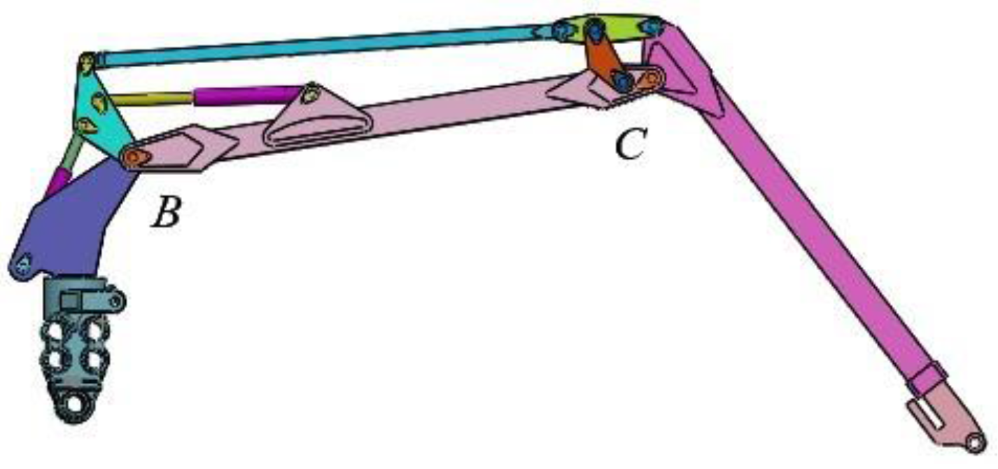
The harvester hydraulic pump translates mechanical energy from the engine into hydraulic energy, drives hydraulic oil to the multi-way valve block, and then, controlled by the cab control, handles the core position of the integrated valve block in accordance with the principle of load sensing control [14]. Its main work progress is turning by rotating bodies, main boom lifts, telescopic boom extension, and other movements [15,16]. The working condition of the harvester boom is relatively complex. The main hydraulic cylinder, the secondary hydraulic cylinder, and the telescopic cylinder are all large flow components, and other hydraulic components interact and work together [17]. A virtual prototype model was created in order to study the boom (Figure 1). Because the harvester boom rotation is limited by the cockpit, the maximum load of the boom is 12,300 N—the sum of the weight of the load that must be able to support the logging head and the weight of the tree. Figure 2 shows the structure of the harvester boom; the linkages are connected by pivot pins. Static analysis of the boom is a prerequisite for dynamic simulation analysis. During the movement of the boom, the maximum bending moment on the end of the boom occurs when it extends to the farthest end of the working range. At this point, the boom acts as a rigid body, and according to the connection of each assembly, the main boom and the secondary boom are articulated in the column on the cantilever beam.
2.1. Calculation of the Main Cylinder
2.1.1. Force Analysis
The main cylinder is the boom’s lifting power in order to provide enough hoisting force [17]. The force does not act directly on the jib, but is transmitted to the jib through intermediates such as the pusher and link, and is then transmitted to the harvesting head at the end of the telescopic arm. The axial force F of the main hydraulic cylinder is calculated on its piston area.
where S1 represents the piston (rodless cavity) area; S2 represents the rod-side annular area of the piston (with rod cavity); F1 represents the hydraulic force acting on the piston (thrust force); F2 represents the hydraulic force acting on the ring area of the side of piston rod (pulling force); represents the max pressure of the hydraulic circuit, value 25 MPa; D represents outside diameter of hydraulic cylinder, value 110 mm; d represents the diameter of the piston rod, value 77 mm.
2.1.2. Column Stability Calculation
The boom’s movement is powered by hydraulic cylinder and determines the stability of the load of the entire boom, so it is necessary to check the column stability of the piston rod.
The secondary moment of the piston rod inertia moment I:
Cross-sectional area of piston rod S:
Critical load of piston rod Fk:
where n represents the end condition factor, the main cylinder for the two-point hinge, value n = 1; E represents elastic modulus value of the piston rod material, value E = 2.1 × 10¹¹ Pa; L represents the length of the piston rod; I represents the secondary moment of the piston rod inertia moment.
2.2. Calculation of the Second Cylinder
2.2.1. Force Analysis
The second cylinder is generally arranged on the main boom, and connects the triangular pusher with the main boom. The axial force F of the second hydraulic cylinder is calculated based on its piston area.
where S1 represents the piston (rodless cavity) area; S2 represents the rod-side annular area of the piston (with rod cavity); F1 represents the hydraulic force acting on the piston (thrust force); F2 represents the hydraulic force acting on the ring area of the side of piston rod (pulling force); represents the max pressure of the hydraulic circuit, value 25 MPa; D represents outside diameter of the hydraulic cylinder, value 90 mm; d represents the diameter of the piston rod, value 63 mm.
2.2.2. Column Stability Calculation
The secondary moment of the piston rod inertia moment I:
Cross-sectional area of piston rod S:
Critical load of piston rod Fk:
where n represents the end condition factor, the second cylinder for the two-point hinge, value n = 1; E represents elastic modulus value of piston rod material, value E = 2.1 × 10¹¹ Pa; L represents the length of piston rod; I represents the secondary moment of the piston rod inertia moment.
3. Dynamic Simulation of the Cylinder
3.1. The Preprocessor of the Boom’s Virtual Prototyping
After importing the SolidWorks model into ADAMS, the ADAMS working environment is set up including units, gravitational acceleration, and grid. The constraints between the different components are defined according to the movement of the various components of the boom. Between the hydraulic cylinder and piston rod, the paper can use translational to analysis. In the ADAMS software, the constraints of each part of the working arm are shown in Table 1.
3.2. The Boom’s Movement Law
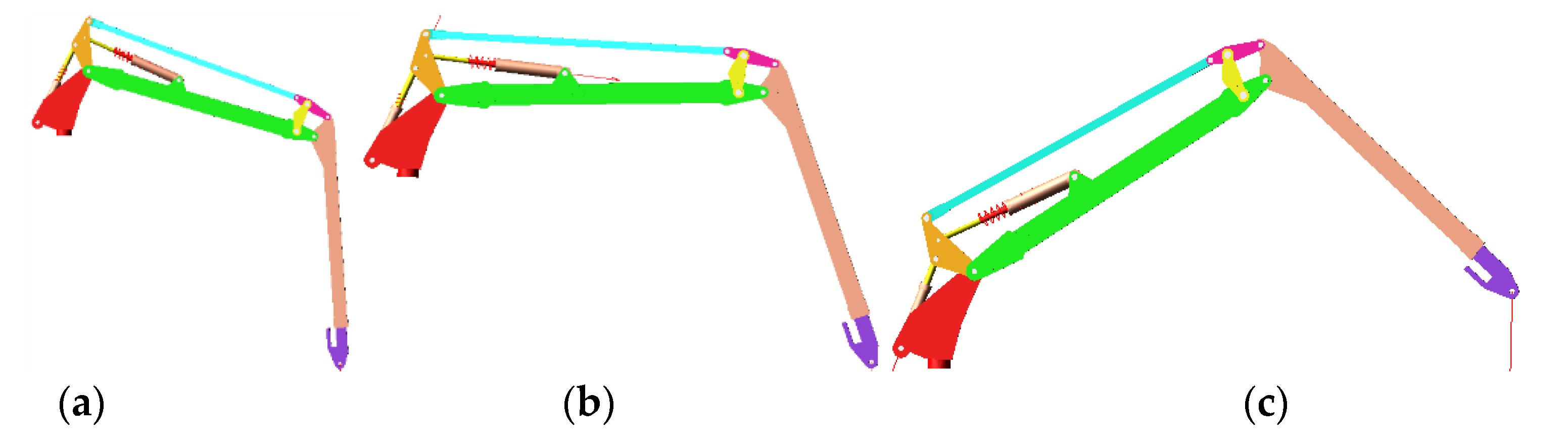
The process of the harvester is a cycle of snatching, luffing, and rotation.It can achieve working conditions with different working range and lifting capacity in the operating range. In the whole movement, the cylinder is the only power controlling the movement of the boom: tilt, sweep, expand. By changing the working position of the boom (Figure 3) several times to complete a whole telescopic process in different states, the force curve of the hydraulic cylinder under various working conditions can be obtained based on the dynamic simulation of the harvester boom. The cylinder force is analyzed in the whole working process. This will help reduce the difficulty of the operator’s work, but also reduce the energy consumption of the machine. In the ADAMS software, there are two kinds of driving conditions of the working arm: one is the main oil cylinder drive, and the other is the secondary cylinder drive.
3.3. Cylinder Drive
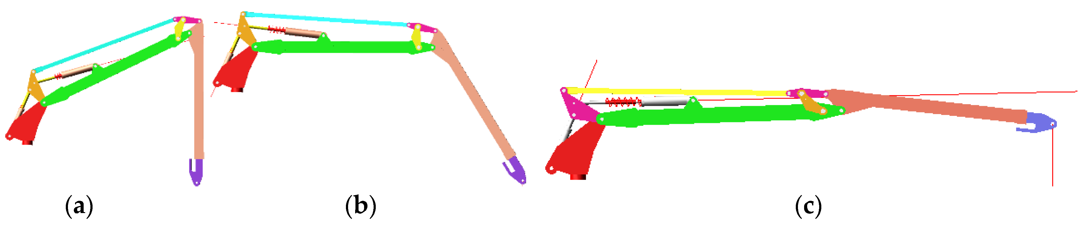
In simulating the main cylinder motion, the drive function is set to realize the movement of the jib and telescopic boom by moving the master cylinder. The extension of the main cylinder can drive the main boom, jib, and telescopic boom to rotate around the hinge point B at the left end of the main boom. The working width and load of the boom are affected by a single telescopic motion. The following three typical conditions are selected from: working condition 1 is the vertical position of the jib (−90°), working condition 2 is the jib at −45° and a horizontal line, and working condition 3 is the extension of the jib to the far end.
3.4. Secondary Cylinder Drive
In simulating the motion of the second cylinder, the main cylinder and telescopic boom movement are determined first, and only the second cylinder can be telescopic. The expansion of the second cylinder drives the jib and the embedded telescopic boom rotating around the hinge point C (the hinge point of the main boom and secondary boom). The working range of the boom and its weight are only affected by the secondary cylinder. The master cylinder is set in different states, the boom is set to different initial working states, and the main cylinder and telescopic cylinder are locked. Next, the simulation drive parameters of the secondary cylinder are set, and the simulation time is set to 10 s. The three conditions show the selection of the first luffing angle as −20°, 0°, and 45° in Figure 4.
4. Results Analysis
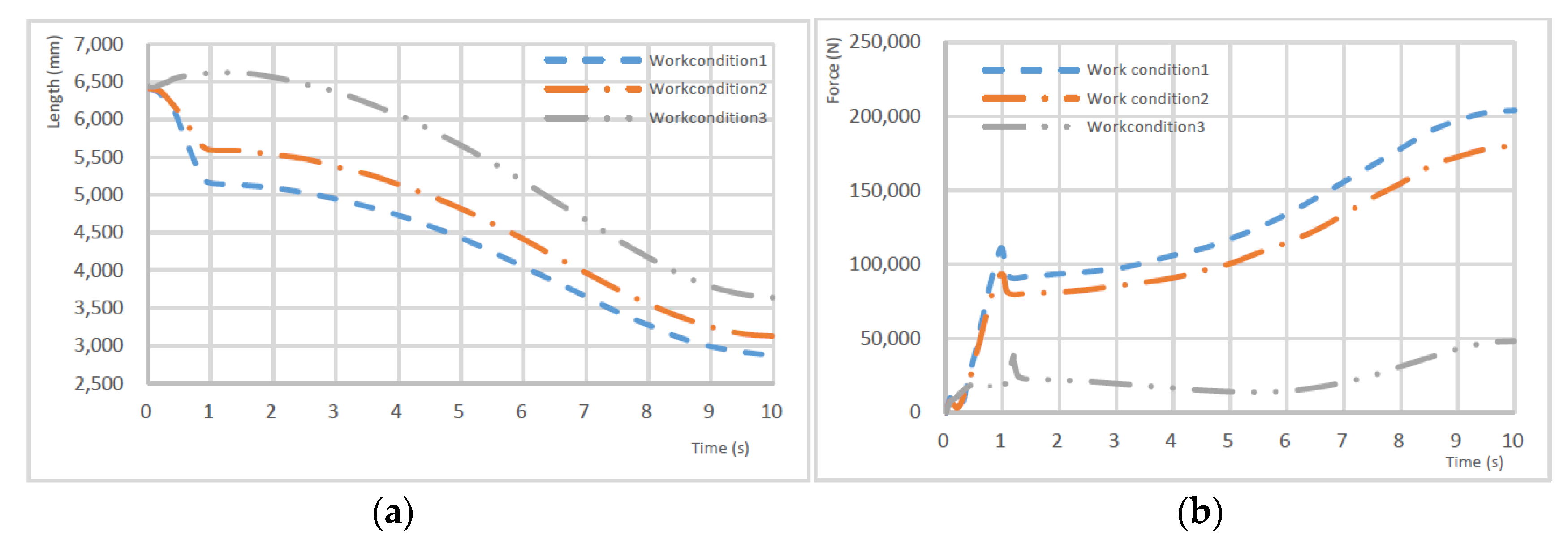
Figure 5 shows that the maximum operating amplitudes of work condition 1, work condition 2, and work condition 3 are 4.8 m, 6.9 m, and 8.2 m. The figure shows the “length” for the end of the main cylinder trajectory, indicating the displacement of the bottom of the auxiliary arm. Figure 5a shows that the motion and work of conditions 1, 2, and 3 are different. This is because the main arm of the working arm is upward sloping as a result of the decision to set the initial position as working condition 1; when the master cylinder is retracted, the main arm to rotate on the side arm will rotate inwards, and the jib low end displacement decreases gradually. The change rules of work condition 2 and work condition 3 are similar. It is obvious that the reachable range of the three working conditions are increasing, as the working position of the telescopic arm controlled by the secondary cylinder is different. According to the load spectrum, the maximum load of working condition 1 can reach 3120 kg, while the maximum load of working condition 2 is 1910 kg, and the maximum lifting capacity of working condition 3 is 1230 kg.
Work conditions 4, 5, and 6 have the luffing angle of the main boom as negative, 0°, and positive. Figure 6 shows that the trend of the displacement of the boom end under three kinds of working conditions are similar, with the movement increasing and the working area being similar. The maximum operation area of work condition 4 is 5.1 m, for work condition 5 it is 5.6 m, and for work condition 6 it is 6.6 m. In order to analyze force change of the main cylinder under different working conditions, the load of the boom end was set to 1230 kg, the simulation time was set to 10 s (the first second is the preparation time of the boom, mainly to adjust movement of the secondary cylinder and telescopic cylinder and lock their luffing movement status), then the luffing motion of main cylinder simulation was carried out. From the force curve of the main cylinder, the first second is the boom’s position adjustment time. From 2 s onward, the force gradually reduced to the end of the action (the boom cylinder has stretching movement under working condition 1, and the force of the main cylinder reaches its maximum. This is because from 2 s onward, the jib is in a vertical position, and the main cylinder is in maximum torque; with the main cylinder’s contraction, the boom constantly lifted upward, reducing the working range. The lift resistance torque was also decreasing, so the force of the main cylinder continued to reduce. After the boom movement, the force of the luffing cylinder increased slowly under work conditions 2 and 3. The main boom continuously lifted upward with the continuous contraction of the main cylinder, and increased to its maximum value. The maximum force of the cylinder is 1.92 × 10⁵ N under work condition 2, while it is 2.33 × 10⁵ N under work condition 3. The data of the six work conditions are organized in Table 2. It can be seen from the table that the force on the sub-cylinder is also different with changes in the initial position of the main boom. With the increase of the boom angle, the boom’s working range was reduced and the force of the cylinder gradually reduced. For work condition 6, with shrinking of the second cylinder, the jib moved from outside to inside, the force of the luffing cylinder reduced, and it reached the minimum value at about 5.5 s. As the cylinder continued to shrink, the process of resistance torque also increased.
5. Conclusions
Analysis of the above conditions shows that the attitude of the boom and the jib affects the working range of the working arm of the harvester when the load is constant and only the boom cylinders are extended and contracted. When the load is determined and only the main boom cylinder changes its stretch, the changing position of the main boom and jib will affect the whole boom’s work area. So, the force of the cylinder increases with the increase of the working range. When the secondary cylinder’s stroke makes the boom reach its maximum work area (work condition 3), the force of the cylinder also reaches its maximum. In harvesting processes, shortening the telescopic boom’s end can effectively reduce the load of the boom and enhance the mechanical efficiency by adjusting the telescopic boom’s initial working state. Generally, the force of the luffing cylinder has a tendency to increase. A 3D boom model was built by SolidWorks software imported into ADAMS dynamics simulation. Taking the main and secondary cylinders as the research objects, the design and calculations were carried out, and three working conditions were selected to simulate and obtain the working range and force of different working positions. The results show that the working position of the main and secondary boom affect the boom’s working range and the force of cylinders. In this paper, the pitching motion of the working arm is the main consideration, and the working arm can also be turned for further study.
Author Contributions
Rongfeng Shen conceived and designed the experiments and wrote the paper; Xiaozhen Zhang performed the experiments and analyzed the data; Chengjun Zhou contributed materials and analysis tools.
Conflicts of Interest
The authors declare no conflict of interest.
References
- Pijuan, J.; Comellas, M.; Nogués, M.; Roca, J.; Potau, X. Active bogies and chassis levelling for a vehicle operating in rough terrain. J. Terramech. 2012, 49, 161–171. [Google Scholar] [CrossRef]
- Shen, R.; Liu, J.; Wang, D. Stroke length of hydraulic cylinder and moving trail of harvester boom. J. Beijing For. Univ. 2010, 32, 157–160. [Google Scholar]
- Grebner, D.L.; Bettinger, P.; Siry, J.P. Chapter 12—Forest Harvesting Systems. In Introduction to Forestry and Natural Resources; Academic Press: San Diego, CA, USA, 2013; pp. 287–302. [Google Scholar]
- Sun, G.; Liu, J. Dynamic responses of hydraulic crane during luffing motion. Mech. Mach. Theory 2006, 41, 1273–1288. [Google Scholar] [CrossRef]
- Sun, G.; Kleeberger, M.; Liu, J. Complete dynamic calculation of lattice mobile crane during hoisting motion. Mech. Mach. Theory 2005, 40, 447–466. [Google Scholar] [CrossRef]
- Chin, C.; Nayfeh, A.H.; Abdel-Rahman, E. Nonlinear dynamics of a boom crane. J. Vib. Control 2001, 7, 199–220. [Google Scholar] [CrossRef]
- Hong, K.-S.; Ngo, Q.H. Dynamics of the container crane on a mobile harbor. Ocean Eng. 2012, 53, 16–24. [Google Scholar] [CrossRef]
- Blackburn, D.; Lawrence, J.; Danielson, J.; Singhose, W.; Kamoi, T.; Taura, A. Radial-motion assisted command shapers for nonlinear tower crane rotational slewing. Control Eng. Pract. 2010, 18, 523–531. [Google Scholar] [CrossRef]
- Hannan, M.A.; Bai, W. Analysis of nonlinear dynamics of fully submerged payload hanging from offshore crane vessel. Ocean Eng. 2016, 128, 132–146. [Google Scholar] [CrossRef]
- Sawodny, O.; Schneider, K.; Aschemann, H.; Kumpel, J.; Tarin, C. Aktives Lastpendeldampfungssystem fur Liebherrauslegerdrehkrane; Herausgegeben als Begleitband zur gleichnamigen Fachtagung: Dresden, Germany, 2001; pp. 1–17. [Google Scholar]
- Araya, H.; Kakuzen, M.; Kinugawa, H.; Arai, T. Level luffing control system for crawler cranes. Automat. Construct. 2004, 13, 689–697. [Google Scholar] [CrossRef]
- Kilicaslan, S.; Balkan, T.; Ider, S.K. Tipping load of mobile cranes with flexible booms. J. Sound Vib. 1999, 223, 645–657. [Google Scholar] [CrossRef]
- Shen, R.; Liu, J. Operation trajectory of harvester manipulator. J. Fujian Agric. For. Univ. (Nat. Sci. Ed.) 2009, 38, 431–435. [Google Scholar]
- Shen, R. Research on Forestry Felling & Cultivation Machine Executive Mechanism and Load-Sensing Hydraulic System; Being Forestry University: Being, China, 2010; pp. 34–38. [Google Scholar]
- Zhao, Z. Kinematics Analysis and Jacobian Matrix Solution for the Manipulator of a Logging Harvester. For. Mach. Woodwork. Equip. 2010, 38, 45–47. [Google Scholar]
- Ge, A.; Tao, P.; Li, Q. Kinematic Simulation and Analysis of the Harvester Arm System Based on ADAMS. For. Eng. 2012, 32, 33–37. [Google Scholar]
- Jiang, F.-M.; Guo, W.-D.; Zhang, P.; Zhao, Y.B. Design and Research of Robot Arm for Transfering Pipette Based on Virtual Prototype Technology. Mach. Des. Manuf. 2013, 25, 94–96. [Google Scholar]
Figure 1.
The boom model and structure diagram.

Figure 2.
Boom structure and force diagram.
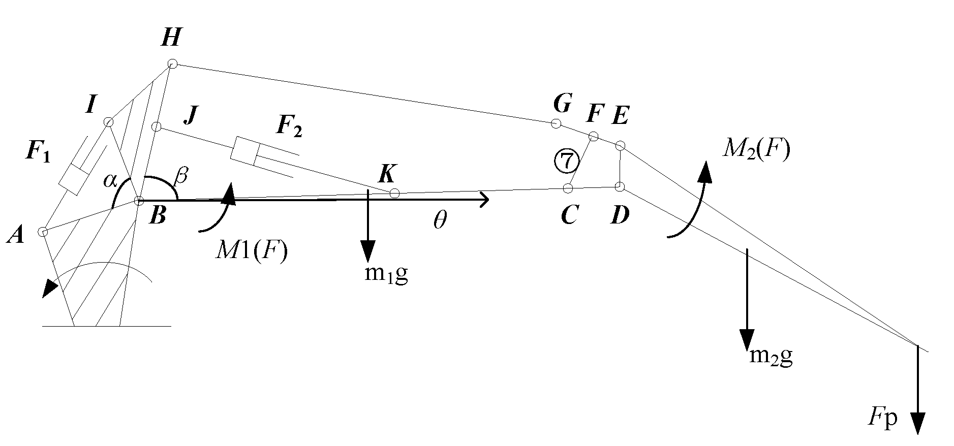
Figure 3.
The main cylinder luffing and three typical operation conditions. (a) working condition 1; (b) working condition 2; (c) working condition 3.
Figure 3.
The main cylinder luffing and three typical operation conditions. (a) working condition 1; (b) working condition 2; (c) working condition 3.

Figure 4.
The secondary cylinder luffing and three typical operation conditions. (a) Working condition; (b) Working condition 5; (c) Working condition 6.
Figure 4.
The secondary cylinder luffing and three typical operation conditions. (a) Working condition; (b) Working condition 5; (c) Working condition 6.

Figure 5.
Simulation of the main cylinder under three typical work conditions: (a) The end of the main cylinder trajectory; (b) Main cylinder force.
Figure 5.
Simulation of the main cylinder under three typical work conditions: (a) The end of the main cylinder trajectory; (b) Main cylinder force.
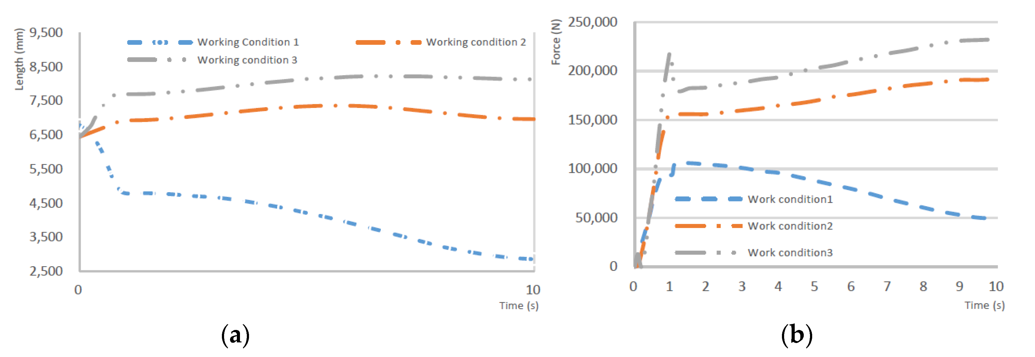
Figure 6.
Simulation of secondary cylinder under three typical work conditions. (a) The end of the secondary cylinder trajectory; (b) Secondary cylinder force.
Figure 6.
Simulation of secondary cylinder under three typical work conditions. (a) The end of the secondary cylinder trajectory; (b) Secondary cylinder force.


Table 1.
Virtual constraints between components of the boom.
| Part i | Part j | Constraint Relationship |
|---|---|---|
| Base | Ground | Fixed |
| Base | Main cylinder | Revolute |
| Base | Boom | Revolute |
| Cylinder | Piston rod | Translational |
| Main boom | Second boom | Revolute |
| Jib | Telescopic boom | Translational |
| Pusher | Puller | Revolute |
Table 2.
The comparison of luffing parameters of main and secondary cylinder.
| Max Working Range (mm) | Max Force of Cylinder (N) | Average Force of Cylinder (N) | |
|---|---|---|---|
| Work condition 1 | 4798 | 1.06 × 10⁵ | 0.78 × 10⁵ |
| Work condition 2 | 6923 | 1.92 × 10⁵ | 1.63 × 10⁵ |
| Work condition 3 | 8235 | 2.33 × 10⁵ | 1.95 × 10⁵ |
| Work condition 4 | 5148 | 2.05 × 10⁵ | 1.27 × 10⁵ |
| Work condition 5 | 5592 | 1.8 × 10⁵ | 1.10 × 10⁵ |
| Work condition 6 | 6630 | 0.48 × 10⁵ | 0.23 × 10⁵ |
© 2017 by the authors. Licensee MDPI, Basel, Switzerland. This article is an open access article distributed under the terms and conditions of the Creative Commons Attribution (CC BY) license (http://creativecommons.org/licenses/by/4.0/).
Share and Cite
MDPI and ACS Style
Shen, R.; Zhang, X.; Zhou, C. Dynamic Simulation of the Harvester Boom Cylinder. Machines 2017, 5, 13. https://doi.org/10.3390/machines5020013
AMA Style
Shen R, Zhang X, Zhou C. Dynamic Simulation of the Harvester Boom Cylinder. Machines. 2017; 5(2):13. https://doi.org/10.3390/machines5020013
Chicago/Turabian StyleShen, Rongfeng, Xiaozhen Zhang, and Chengjun Zhou. 2017. "Dynamic Simulation of the Harvester Boom Cylinder" Machines 5, no. 2: 13. https://doi.org/10.3390/machines5020013
Note that from the first issue of 2016, this journal uses article numbers instead of page numbers. See further details here.