1. Introduction
The recent evolution of manufacturing systems was initiated with the so-called Computer-Integrated Manufacturing (CIM) in the 1980s, as a way to automate, optimize, and integrate all the manufacturing processes. During this decade, with the studies of Llorente et al. [
1] and Burgos et al. [
2] as examples from those years, CIM grew towards robotics introduction, the development of artificial intelligence (AI), and the use of flexible manufacturing systems (FMS) in order to reduce the work-in-process (WIP), system breakdowns, and manual work and costs, allowing the adaptation of the systems to the rapidly changing products and batch sizes. Simultaneously, a new concept called Total Quality Management (TQM) was undertaken to consider the effects of all of the agents involved during the product life cycle, in order to improve product features and meet the customer expectations.
Progressively, the CIM concept, aided by the TQM, just-in time (JIT), or more recently with the ideas of
lean manufacturing principles faded slightly in fashion, only to return again at the 2013 and 2015 EMO machine-tool exhibition fairs. The most successful companies started to implement new concurrent and multi-disciplinary strategies (outsourcing, full-service supply, offshore manufacturing, and joint ventures) closely connected with client requisites. Then, open architecture manufacturing and agile manufacturing [
3] appeared as emerging trends in automation, as the so-called 4th Industrial Revolution. In the past, proprietary designs allowed developers to create controls with unique characteristics to be involved in proprietary architecture, making them more difficult for competitors to copy. This protection method worked well for those years, when any control technology developments lasted at least 4–5 years. Now that the lifecycle is much shorter (6–8 months), proprietary control developers require longer times to incorporate new technology into a proprietary design than the own technology’s expected life. To remain competitive in terms of both cost and technology, Computer Numerical Control (CNC) manufacturers are now forced to find better ways of updating controls to sudden technological changes other than launching huge development projects each time a technology change is needed. Open architecture has provided and currently provides that capability.
On the other hand, an emerging trend over the last 20 years is the Digital Manufacturing approach (DM), defined as the integration of simulation, 3D visualization, and analysis [
4,
5]. Digital manufacturing evolved starting from computer-integrated manufacturing (CIM), enlightened by the need of greater collaboration between product design and process planning. 3D simulation tools opened the implementation of virtual model machines, robots, workcells, and assemblies, but also included the factory production lines and workflow; all the factors involved in the complex production environment. Nonetheless, many of the long-term benefits of Product Lifecycle Management (PLM) cannot be achieved without an integrated digital production strategy [
6]. The process chain coordination allows manufacturing companies to achieve their short time-to-market requirements, production volume targets, and cost saving strategy. Today, digital manufacturing is based on the integration of Computer Aided Design (CAD)/Computer Aided Manufacturing (CAM) applications on PLM tools.
Thus, CAM allows “virtual cutting tools” to be driven over digitally rendered part surfaces, producing a code to be used by the CNC to drive “real tools” in the workpiece. Currently, virtual simulation tools can build virtual models of the (i) machine tool; (ii) workpiece; and (iii) cutting tool, as well as simulate the machine movements and the consequent material removal, allowing for a rapid checking of interferences, excessive tool engagement, and collisions. The risk of an impact caused by a wrong machining operation is a continuous nightmare for any machine programmer, worker, and managing director. The concept of
virtual manufacturing (VM) makes reference to reproducing a complete virtual model of a machine, its processes, and auxiliary devices [
7]. This allows for visualizing the feasibility of a process without using any real test. If the evaluation is positive, the operations are then translated into the real production facility. Following the thread that started from the digital and virtual manufacturing ideas, the virtual machine tool (VMT) concept appears as a multi-approach software platform in which users can interact to evaluate different machine tool architectures.
For instance, complex operations may require hours of preparation for the machine setup, during which the machine tool is unproductive; the use of expensive production machines to form operators is another example of productivity losses. Many companies try to make exhaustive use (on a 24/7 basis) of their production facilities, therefore the use of “virtual machines” is a good way to eliminate idle times. However, always when machines are switched on, it is important that there is 100% confidence that there will be no collisions, interferences, or excessive tool engagements into the workpiece [
8]. Instead of the traditional checking of CNC programs
step by step, the VMT verifies them in ordinary PCs [
9]. The VMT is a toolkit of software components: a 3D model of the machine tool with machining simulation software and a machine/human interface (MHI) [
10]. The organizational logic of the virtual system is divided into two functional axes. One axis characterizes the machine tool structure under certain conditions (loads, temperature, etc.), while the other is related to the motion of the machine elements and associated errors. The programmed motions, possible errors, deformations induced by the process force, and the heating from several sources lead to a relative motion between the tool and the workpiece, which forms the workpiece final surface. A high-end VMT must predict cutting forces, temperature variations, and the final outcome which will be the dimension/roughness of machined parts. During post-processing, the VMT graphically simulates and verifies the programs. To date, process models included in VMT are very simple, with no use of deep process models; this lack of deep process models was the opportunity for the present approach.
Internet-based manufacturing is improving communications between manufacturers, clients, and suppliers [
11], and it has a key role for shortening the time-to-market [
12]. Information integration is now being called Industry 4.0. Industry 4.0 is the high-tech strategy promoted by the German government, which promotes the computerization of traditional industries such as manufacturing. The goal is the intelligent factory (Smart Factory), which is characterized by adaptability, resource efficiency, and ergonomics, as well as the integration of customers and business partners in business and value processes. The technological basis is cyber-physical systems and the Internet of Things. It is expected that future wireless plant-floor networks will remotely control manipulators and robots, as well as CNC machines.
On the other hand, remote-monitoring is already offered by some big machine tool builders. For instance, the machine e-Tower of Mazak® offers a virtual assistant for setup and maintenance support in-office or off-site aimed at management functions, work scheduling, mobile alerts, etc. The Web Monitor of DMG-Mori Seiki® connects any machine tool to a web-based platform. In both cases users can log in to the control to access this information remotely from any internet-connected device and see an up-to-date status of their machine operation.
The work presented here describes a new utility for the prediction, assessment, and surveillance of machining processes in manufacturing plants. The modular software includes the ability to predict key magnitudes in the machine processes from models involving the static and dynamic behavior of the machine/part system. It also works with experimentally acquired signal data, for a priori or in-process decision making. Due to this plural conception, the software can be used at different manufacturing stages, either at the process definition steps (clamping design for a component, selection of machine tool architecture), machine programmer, or even in-situ by the machine operator. Therefore, it could be an essential “intelligent utility” for structuring the process stages.
Section 2 overviews the recent advances related to software integration in manufacturing activities and
Section 3 presents the development of the software in the C-Sharp programming language (C#) [
13].
Section 4 defines the basics from the underlying mechanical concepts and finally
Section 5 shows two successful applications to real industrial problems.
This approach solves the usual gap between the current commercial VMT utilities and the academic machining process models.
2. Models in Machining Processes
The aforementioned state of the art brings up the necessity for simulation packages that represent the production system performance. Although most common machining problems were solved partially in the literature, it appears that the available solutions are more frequently used in the academic or scientific community rather than being adopted by industrial sectors. To overcome this gap, and in plain words, to achieve the objective stated as “put models to work!”, intense efforts have been carried out in recent years [
14]. The solutions may be classified depending on whether the optimal cutting parameters are chosen
before (predictive, off-process) or
during cutting (in-process, so in a reactive way).
On the one hand, predictive or offline methods [
15,
16,
17] can help to determine machining chatter-free conditions. They are applied before cutting but need experimental information about machine/workpiece dynamics and cutting parameters. For instance, Cutpro
® developed by Prof. Y. Altintas is a well-known simulation software for chip removal processes that solves the process stability equation in the frequency domain [
18]. Recently, this laboratory released new more complex software, MACHpro
®, to integrate the compliance of a given system into a CAM module aimed at tool path optimization (both trajectory and cutting parameters) from a dynamic point of view.
On the other hand,
in-process methods monitor machining of significant magnitudes such as power consumption or vibrations, which are analyzed in real-time, acting through a rapid variation in the machine spindle speed. The onset of chatter is identified by comparison with a threshold value. As the main drawback of this reactive approach, chatter/vibration marks are imprinted on the workpiece before any cutting parameter modification is commanded. For instance, Accord Mill
® records the sound signal during cutting, which is then noise filtered and post-processed before being transformed into the frequency domain. The optimum spindle speed is calculated from the measured vibration frequency, the natural frequency of the system, the initial spindle speed, and the end-mill number of teeth. Similarly, Harmonizer
® is able to determinate the chatter frequency just by measuring the Acoustic Emissions (AE); in two or three iterations the program is able to find a spindle speed where the cut would be stable [
19]. However when the machining depth of the cut is too high or in finishing operations where the vibration modes notably vary (in magnitude and direction along time), this solution has a difficult convergence. So, the system is useful for 1 degree of freedom (DOF) systems and for rough to medium machining operations. Normally, such types of software allow for introducing information from real cutting tests for feedback, and to tune the predictive analysis. For instance, the MetalMAX
® package offers a complete modal characterization module (TXF), prediction software (MilSim), and the Harmonizer module to obtain the recommended new spindle speed.
However, all these models run in a stand-alone basis, with no integration with other control manufacturing stages. This is a drawback solved by the present approach, where efforts concentrated on the use of models instead of their precision; the latter is where scholars usually lose themselves.
3. Software Used for the Integrated Approach
From the CAM stage to the finished product stage, the need of integration over the different production steps is a key issue to maintain market demands. For this reason, the authors developed innovative software, named Dynpro
®, which integrates the models developed during the last few years concerning static and dynamic behaviour (
Section 4) of the turning, boring, and milling processes. The development tool Visual Studio was selected for the program code, due to its multi-step nature. Additionally, MATLAB was used to create other different modules in which numerical calculations are required.
Regarding setup requirements, Dynpro® only uses 50 MB of memory. The program may run on the Windows Vista, Windows 7, 8, and 10 platforms. Users should install the Matlab Compiler Runtime program to get access to the Matlab functions as well.
3.1. User Interfaces
This section shows how the utility addresses diverse machining problems, from the input data to the final graphs that will help the user in decision making.
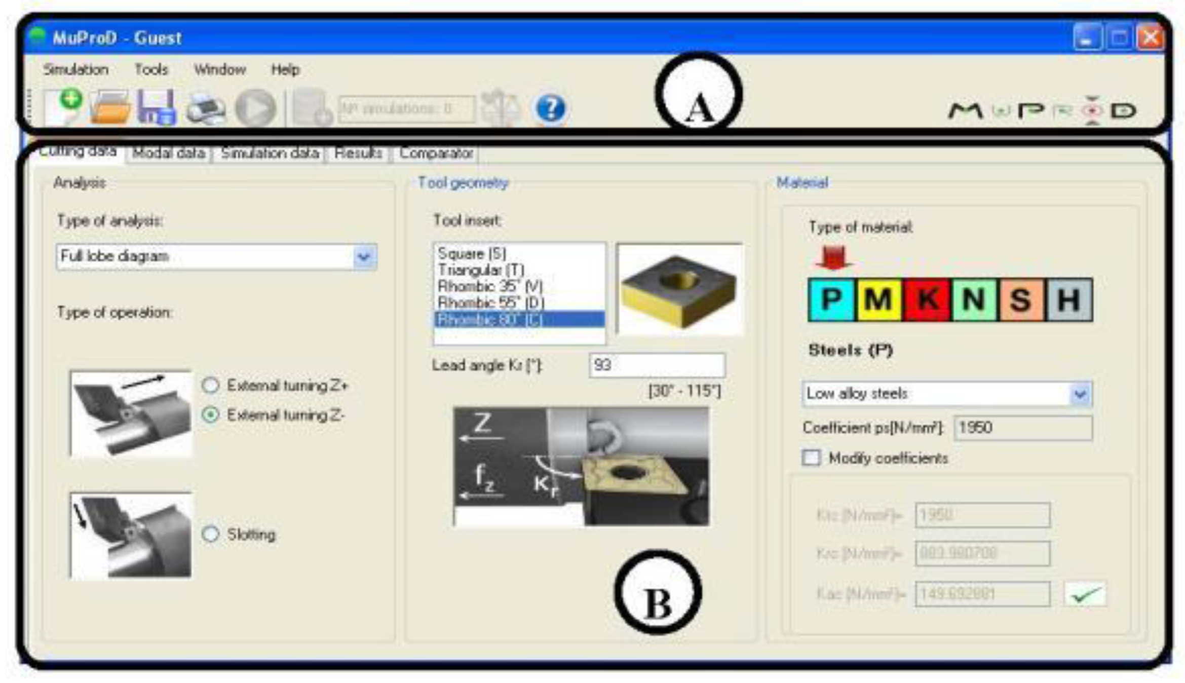
Figure 1 shows the typical interface. Thus, on the top side of screen (A), the toolbar menu presents access to program options such as Simulation, Tools, or Help, as well as to different shortcuts for fast actions. On the lower side (B), the user must fill in the input data to get access to the following tabs. As seen, the system operator is only asked for data in a technical-native language and is always focused on the machining operation, solving a typical drawback of several machining simulation softwares mentioned above, in which a lot of previous knowledge about the fundamentals and basis of equations dominating the process is needed; in general, this was a common drawback that had, and still has, set back the spread of approaches by 20 years, similar to that presented here. The main interface uses codes, pictures, and options related to machining that are used by all machining users. All machining parameters are involved in the initial windows and forms.
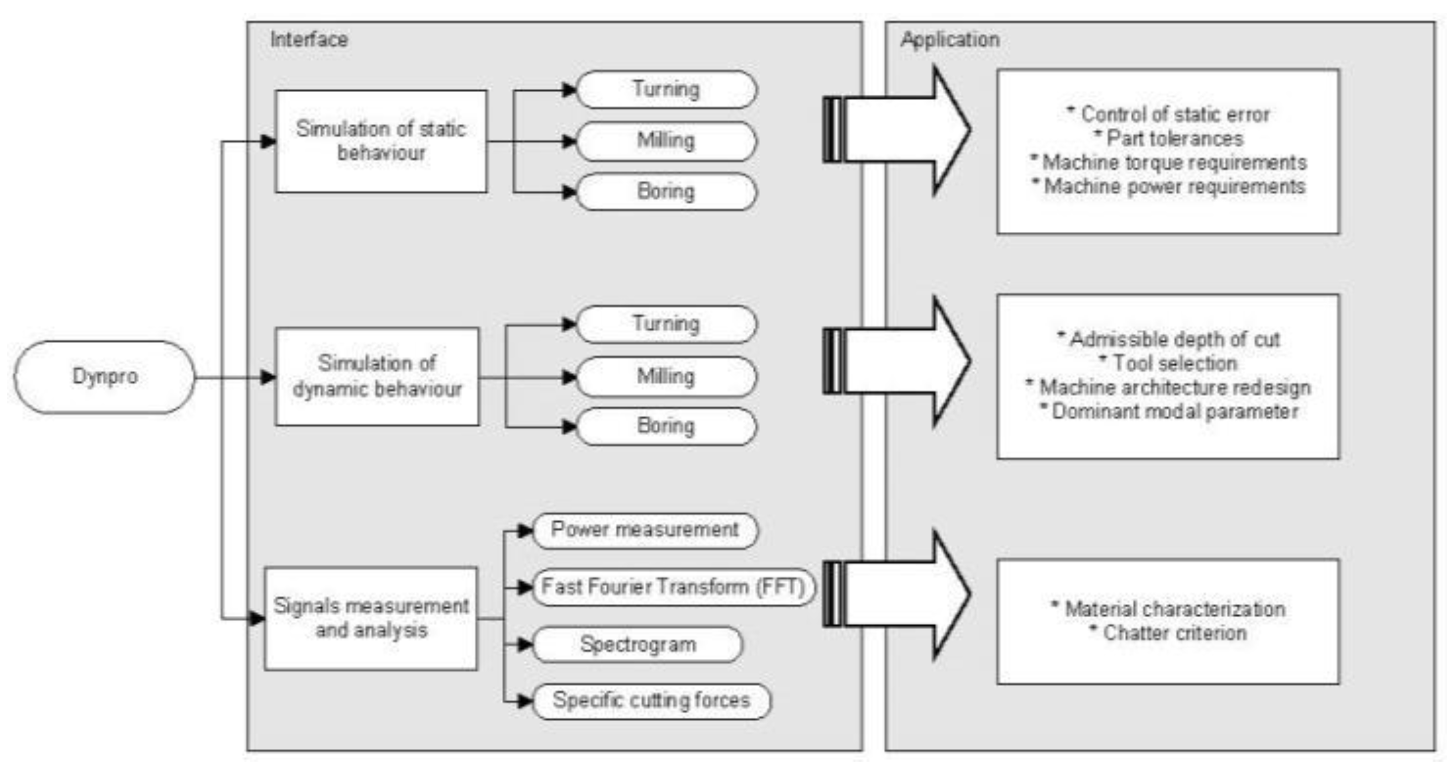
The software is divided into different modules: simulation in static conditions (Simulation of static behavior), simulation in dynamic conditions (Simulation of dynamic behavior), signal measurement, and recording and post-processing. As shown in
Figure 2, the program focuses on the most common chip removal processes, namely, turning, milling, and boring. A database ensures the integrity of the machine and process data.
The static behaviour module calculates cutting forces, roughness, power consumption, or torque. These can be valuable for predicting the static deformation errors. Otherwise, the simulation provided by the dynamic behaviour module obtains the stability lobe graphs of the systems with complex dynamics. Both modules can be useful for the optimization of the machine tool or for the design of complex cutting tools (i.e., serrated-edge tools or variable pitch end-mills).
The third block accounts for an in-situ approach to the machining process with the ability to either record cutting signals or to post-process and manipulate them to obtain cutting forces, specific cutting energies, etc. It is also possible to judge the quality of the machining process by comparing the peaks of the frequency spectrum with respect to the natural frequencies of the system or the multiples of them.
The integration of the mathematical models into the software was made through the creation of a Dynamic-Link Library (DLL), made using the Matlab toolbox.
3.2. Simulation under Static Mechanical Conditions
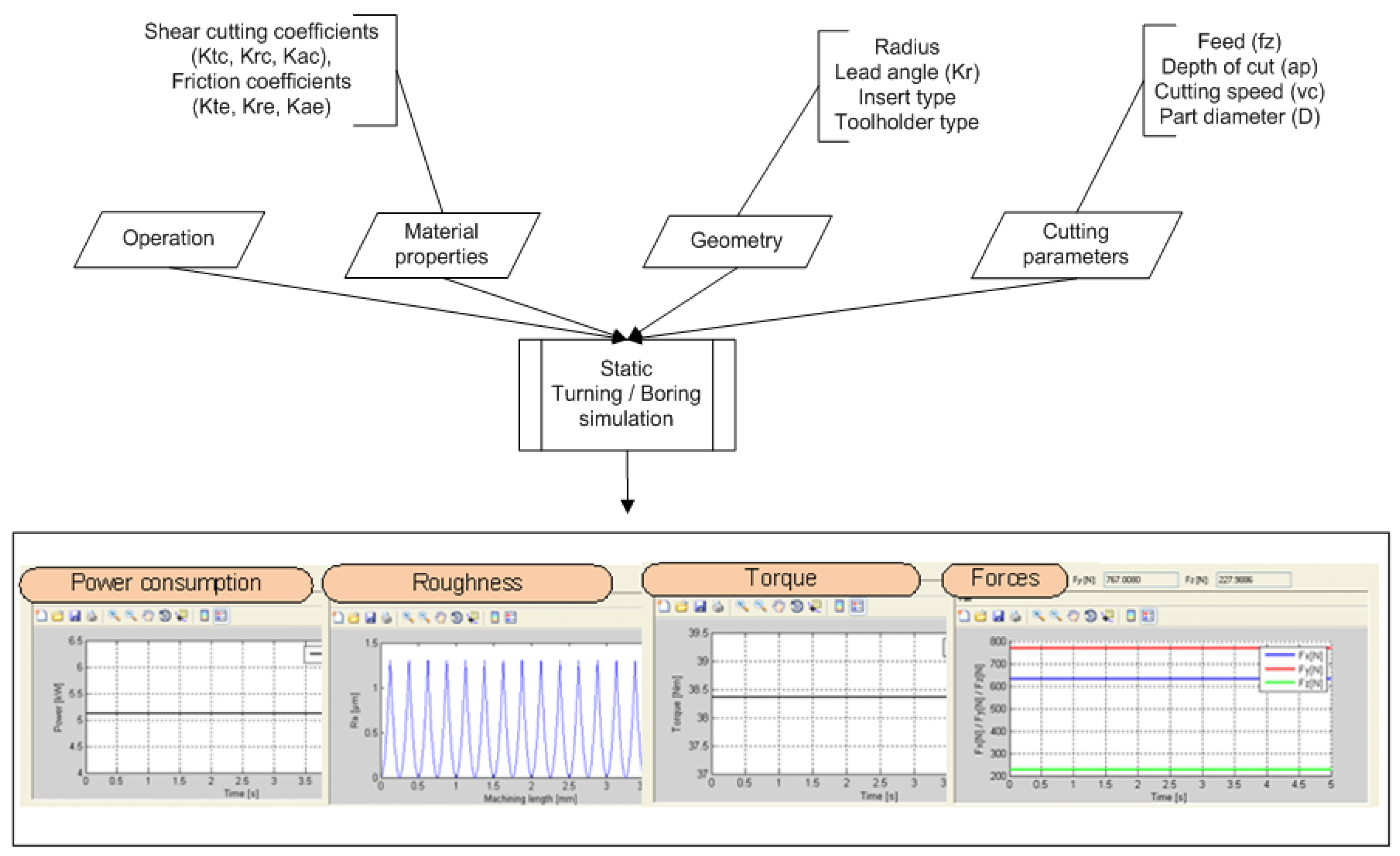
The toolbox “Simulation of static behaviour” is based on the
mechanistic cutting force model developed in
Section 4.1, which assumes a proportionality law between the forces and the removed chip section. From this relation, the software predicts the three force Cartesian components for a wide combination of operations, tool geometries, part materials, and cutting parameters (
Figure 3). The module is completed with additional tabs for the calculation of the roughness, power, and torque consumption in stable conditions (without vibrations).
The user must introduce the machine tool, and the tool or piece stiffness values, usually referred to as the weakest points in the machine workspace. After doing so, the module may help in estimating possible deformations during cutting, making it possible to prevent them by varying the cutting conditions (tool geometry, cutting parameters). Different machining conditions can be easily simulated to select the best choice. In addition, a fast tab for the roughness calculation can be run to predict the estimated roughness. Considering these two features together, a balanced decision can be made between productivity, dimensional accuracy, and surface roughness.
3.3. Simulation of the System with Dynamical Behavior
Chatter problems are a typical constraint for achieving a high productivity, appearing sooner or later in most of the machining operations. Chatter vibrations can cause (a) surface marks that lead to part rejection; (b) tool breakages or (c) even severe damages in machine tool spindle bearings. With Dynpro
®, the user would be able to predict those dynamic problems by obtaining the so-called “stability lobes”. These graphs define the boundary between the stable and unstable cutting conditions (plotting Spindle speed S vs. Depth of cut a
p) in the working range once the dynamic features, tool geometry, and material properties are fed into the model. In
Section 4.2, the basics from the numerical method implemented in Dynpro
® will be presented. Both the turning/boring [
20] and milling models [
21] have a similar code structure.
In the simulation of the dynamic module, the user must introduce the process kinematics, tool geometry, and material properties in the first tab. Then, the modal parameters of the machine and tool couple are loaded (from the database) or are asked from the user as well. Dynamic parameters are obtained by impact tests using an instrumented hammer and a vibration analyzer, through the calculation of the dynamic response function (DRF). Accordingly, Dynpro® includes an innovative toolbox to filter and fit the frequency response function (FRF) archives to the modal parameters, which are easily recognized and used by the program. These are then directly set by the keyboard in the Modal parameters tab. Otherwise, a *.txt archive with equivalent information can be loaded. Once the modal parameters are loaded, a final tab with the simulation parameters must be filled.
The output data are the stability lobes but, depending on the selected type of analysis, other graphs are also available such as [Maximum allowable depth of cut vs. Lead angle] or [Maximum allowable depth vs. Type of process].
3.4. Signal Measurement and Analysis
The third module in the approach allows the user to record and analyze some parameters during machining. Signal measurements are usually linked with the use of costly additional equipment (Kistler
® dynamometer, Artis
®, vibration analyzers, data acquisition cards DAQs, etc.), all of them common in a usual workshop. The Dynpro
® software has a power toolbox for in-process power measurements that makes this task easier. Additionally, a low-cost device is implemented for measuring the power directly from the machine servodrives, using an Ethernet connection. After that, the user can post-process these time signals, for example, to obtain estimations of the specific cutting energy. Once the threshold value for the power consumption in stable cutting is defined, this feature can be used either to predict tool breakages or to keep wear under control [
22].
Also, a signal analysis utility is integrated in this module. In this case, a recorded time signal is visualized, filtered, or post-processed (FFT, spectrograms, etc.) to obtain direct information of the system performance during cutting and to help the machine user in decision-making for keeping the manufacturing system in the best running status.
3.5. Resources
The distribution of the different functions and tasks into independent modules, referred to here as resources, makes both the computational times and the programming easier. In this section, an overview of these resources and their functionalities is summarized.
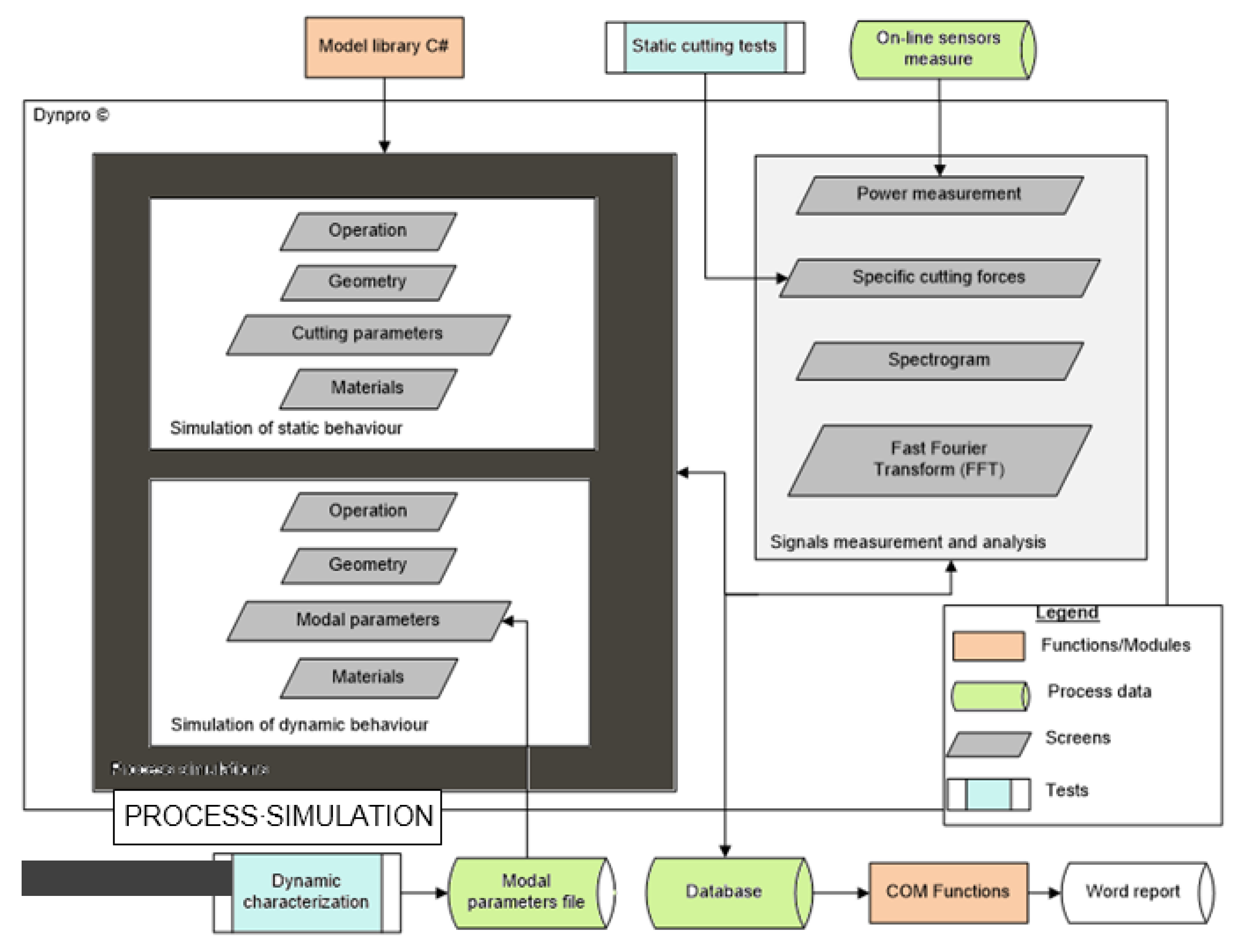
Figure 4 depicts the work flux showing the dependency among the software modules (Simulation of static behavior, simulation of dynamic behavior, and signals measurement and analysis) and the resources. These have been classified into three groups: Functions/modules, Tests, and Process data.
The first group refers to the various programming functions packages (libraries) used by the modules. Libraries are then sub-classified into the ones predefined by the programming interface (or COM Functions) and the ones created exclusively for the project (i.e., Model C# library). The test group works with the experimental information brought to the software from the user-defined experiments (machine tool dynamic measurements, machining noise, etc.). Finally, the process data group describes and identifies the selected format and specifications for the data management and storage.
3.6. Functions and Modules
On one hand, the function or module packages arise from the need of grouping and arranging each of the functions to its own model. Dynamic-Link Libraries (DLLs) were developed for easy programming in C#. On the other hand, Matlab® offers an integrated development environment with a custom programming language, which is the most appropriate option for developing these libraries. Using this programming design, a black box utility isolates the analytical expressions of the model from the Dynpro® interface.
Other Microsoft® Windows functions were used to generate the report of the simulations. These functions, which belong to the Visual Studio development kit, allow the creation of a Word document from the simulation data obtained by Dynpro®.
3.7. Tests
For a more realistic approach, a module to introduce real data from user-defined experiments was designed. This module interacts and uses real (experimental) data and then may serve them to other different modules as input data. Previous experiments made by users are gathered in the database for helping future cases, providing for instance, modal data analysis.
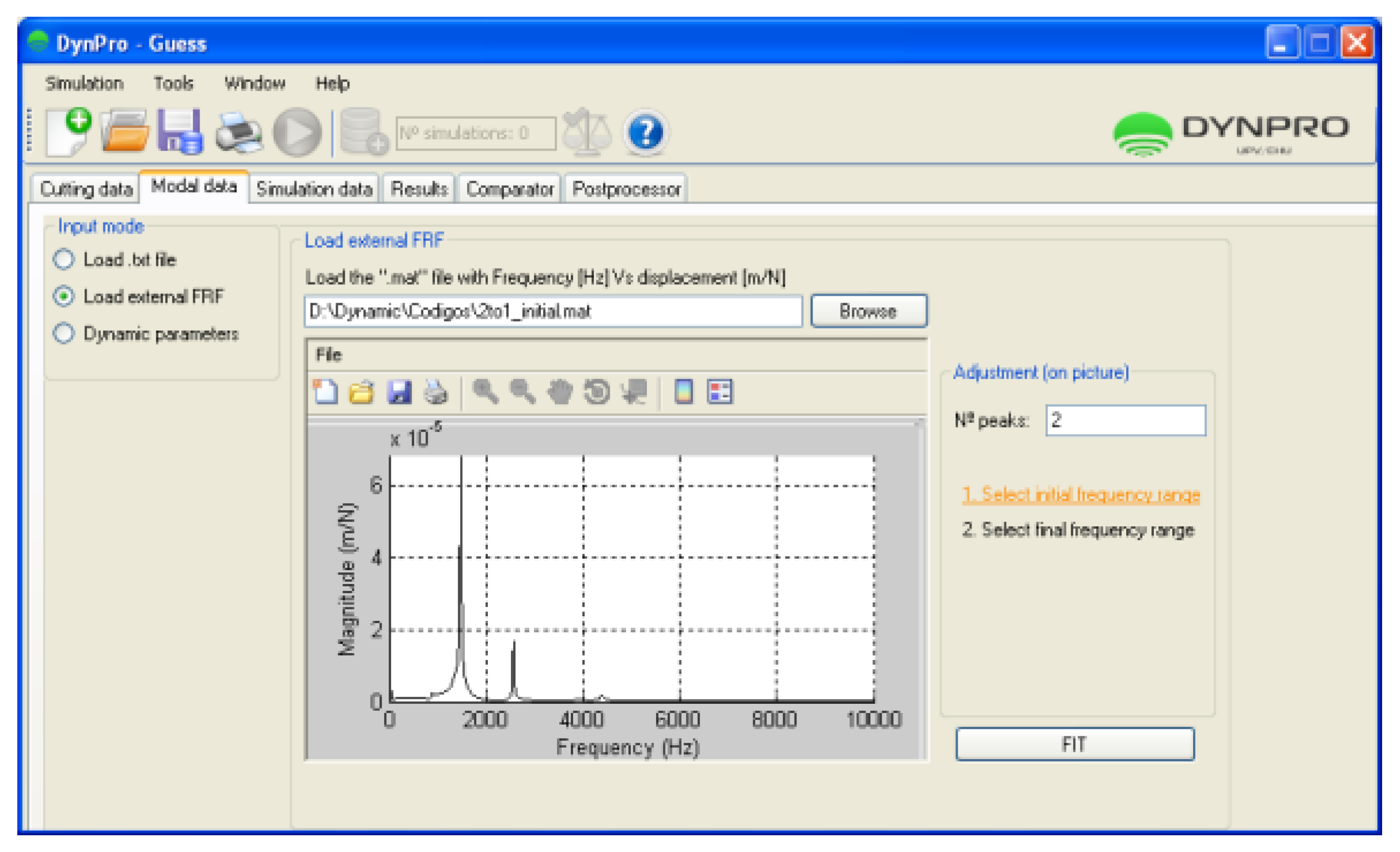
For instance, in the simulation module of dynamic behavior, the program requires some input variables (
Section 3.1) such as modal parameters. Dynpro
® offers a toolbox for obtaining and fitting the modal parameters (peak-picking) once the frequency response function (FRF) has been obtained (by impact hammers or shakers), shown in
Figure 5.
Additionally, the software may be used to help the characterization of raw materials considering machinability. Moreover, machinability can be expressed in the function of the so-called cutting coefficients. These can be taken either from the material database of Dynpro® or, if the user has undertaken experimental tests for material characterization, they may also be edited (and loaded) by the keyboard.
3.8. Process Data
The program data distribution allows Dynpro® to reduce waiting times and unnecessary data loads, by implementing a database to save all the simulations. The features of a commercial well-known database fit in well with the required amount of data to be saved.
Its content is divided into four tables (users, materials, tools, and simulations). Database access is performed using the predefined functions of Visual Studio (Object Linking and Embedding for Databases (OLEDB)). The available capabilities are implemented by using COM objects—the OLEDB supplier links the functionality of one technology to the selected COM interface. It marks a clear boundary between (i) the code that calls a method and (ii) the code that implements the method; in computer science terms, the caller is decoupled from the implementation. The program uses the following classes to access the database: OleDbCommand, OleDbConnection, OleDbDataAdapter, and OleDbCommandBuilder.
The modal parameter file is the result of the dynamic characterization. Those data have to be encapsulated in a text file following some specifications. The approach records it directly, or additionally Dynpro® allows user to create an easy-to-use parameter file by just introducing the machining system dynamic behavior specifying the frequency, stiffness, and damping of each mode.
4. Inside the Software: The Deep-Model
The section explains the model basis. More effort must be made to consider the available process knowledge in order to improve the component properties (accuracy of shape and dimensions, surface finish, and subsurface layer properties) and process parameters have to be based on product-related production requirements. Some of the information that the day-to-day metal cutting practitioners find valuable are the prediction of tool life (wear), prediction of the accuracy of the part being machined, prediction of the surface finish and integrity, and prediction of the mechanical loads on the tool/workpiece/fixtures. Machining processes/operations models are framed into different categories:
Analytical models, out of use currently.
Mechanistic models based on the concept of specific force. They are precise enough and executed in milliseconds, and are suitable for being used in real production.
Finite Element Models to represent chip deformation, but are too slow to be use in daily production. FEM is a tool for other types of analysis, for example fixture design.
AI-based models based on neural/Bayesian networks or on fuzzy logic. Without a model based on the chip removal mechanism, these are useless.
In this section, the authors resume the basic concepts related to the static and dynamic modelling used in the present approach. These are a combination of the theory of mechanistic models [
23], numerical models [
16,
20], or frequency domain techniques [
24]. Modelling is key in several processes [
25] such as deformation, welding, and others, with machining being a real need.
4.1. Cutting Force Prediction
In each machining case, the machine tool, cutting tool, and workpiece form a very complex structural system, with a complicated dynamic behavior. For this reason, predicted forces before cutting are a first-order input when workers program toolpaths at the CAM stage.
In every machining process [
26], the cutting force can be obtained from the projections of a total force
F in the three machine tool Cartesian directions
XMT,
YMT, and
ZMT or in the local tool axis (using in this case the indices:
c, cutting force;
t, tangential force; and
r, radial force). The mechanistic approach assumes that force components are composed of two summation terms, one responsible for the shearing mechanism related to the chip formation mechanism and depending on the chip section (
ap∙f or
b∙h) and the other related to the friction of chip sliding onto the tool rake face that is proportional to the engaged edge length (or chip width
b). Generally, the cutting forces can be expressed as:
where
Krct,c and
Krct,e are the cutting and friction
specific coefficients respectively, which depend on the chip section (
b*
h) and chip width (
b). With slight differences, similar relationships are found for the other processes such as boring or milling. Once these coefficients are defined, the mechanistic model predicts the static cutting forces based on Equation (1). In other words, Dynpro
® makes use of the cutting coefficients (obtained either from a material database or from user-defined ‘previous experiments’) to calculate the cutting forces. It also predicts the cutting forces in finishing operations including the effects of any particular tool geometry (with nose radius
rε and cutting edge angle
κr).
From the cutting force calculation, other parameters such as torque and power consumption are estimated. Those are important magnitudes for tailor-made machines subjected to strict part specifications and power requirements. Moreover, knowing the cutting forces for any tool geometry can be used during the tool design by tool makers to guarantee tool functionality in terms of mechanical tool stresses and tool life.
4.2. Chatter Avoidance
Chatter vibrations occur due to dynamic interactions between the tool and the workpiece. Chatter is caused by a regenerative effect in the chip section between successive cuts, responsible for this dynamic instability. Depending on the feedback system gain, chip width b, and spindle speed S, the system may be stable or unstable. To avoid regenerative chatter, predictive maps or stability lobes have been used for years. From these, the optimal combination of spindle speed and depth of cut can be defined to meet both productivity and security.
The approach integrated in Dynpro
® to study stability combines the collocation method [
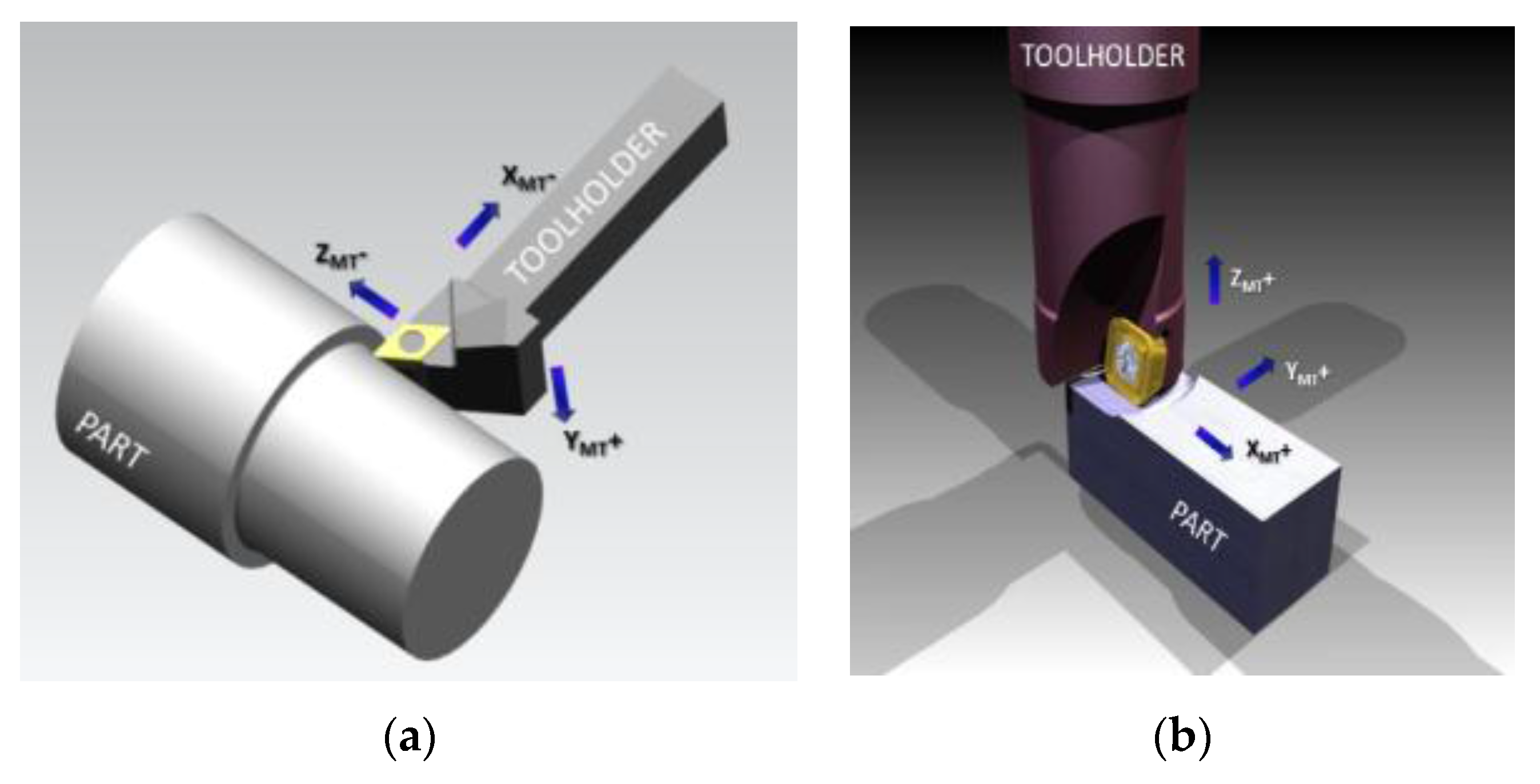
27] which is a numerical method with the dynamics of the machine tool in modal coordinates. The multi-mode approach takes into account the orientation of the machine tool modes. This modal vector is referenced to the machine-tool axes, denoted
XMT − YMT − ZMT. Thus in turning,
XMT defines the radial direction,
YMT the cutting speed direction, and
ZMT the feed (or axial) direction, in a common straight turning operation (
Figure 6a). One frequency mode is defined by two angles:
βy, the angle between the modal vector i
m and the
XMT − ZMT plane and
βxz, the angle between its projections over the
XMT − ZMT plane with respect to
XMT. In milling (
Figure 6b), the machine tool axes are different from the tool local axis. Here,
ZMT is defined by the rotational motion of the tool (or axial) and
αf is the angle between the feed direction (
XT) and
XMT. The modal orientation is defined through the angles
βz, between i
m and its projection in
XMT − YMT, and
βxz, between the projection of i
m and
XT.
αx is the sum of the angles
αf and
βxy.
From this approach, the dynamic equation for n modes is defined as:
where [
M] = [
I] and [
C] and [
K] are the damping and stiffness matrices defined as:
and the right
term {g} represents the delay term responsible for the regenerative effect. Starting from the equation of motion, a numerical method (named the Chebyshev collocation method) is used to approximate the solution to the stability problem.
Using this approach, the model easily recognizes the influence of modes acting with different orientations. As for the simulation of the static behaviour module, the positioning and tool geometry can also be considered.
5. Application to Real Cases
The full model was put to work in two case studies. The first one is related to the module that predicts the machine behaviour under a quasi-static regime (no vibrations), while the second one has been selected to verify the capabilities of the dynamic module. In the latter, this module should predict reliable stability boundaries to ensure both stable and productive machining.
5.1. Case Study 1: Design of Clamping Systems
The following case study was a planet-carrier manufacturing. Normally, the workpiece involves turning, boring, and slotting operations, performed in large vertical turning lathes. These parts require tailor-made clamping systems to avoid (a) static deflections and (b) vibrations during machining. A good clamping design should allow for a reliable machining, keeping the workpiece within the specified tight tolerances. This requires a proper clamping of the part to mitigate the deformation of the weakest part features, such as flanges or slender wings. In this case, the holistic approach was and is still being applied to avoid excessive deflection of the component during machining.
First, the whole [machine tool-part assembly] stiffness was experimentally analyzed. The stiffness calculation must be corrected, discounting the compliance of the measurement devices. Then, for the coupled tool-workpiece, the cutting forces were obtained from a set of cutting conditions, tool geometries, and workpiece materials. Finally, a deformation model may be proposed for the machine. This will allow for the analysis of the part-fixture-machine assembly. Once the cutting forces are known, the static deflections may be predicted and controlled.
For the system stiffness determination, a series of experiments were performed. Stiffness is determined as the ratio between the force applied at a determined point and the deformation of the mechanical system measured at that point as well. In this example, the excitation force was applied by moving the lathe ram against the part by a hundredth of millimeter, putting the dynamometer between the tool tip and the upper part of the cylindrical shape workpiece. The applied forces were measured using a strain gauge dynamometer, in which flexibility must be taken into account. As shown in
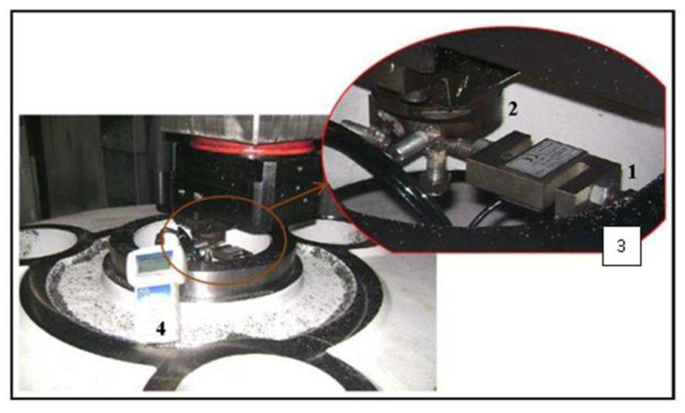
Figure 7, the dynamometer was placed in order to measure the stiffness of the part (marked as 3 in the figure) in the three spatial directions.
Bearing in mind the machine tool-workpiece assembly, two degrees of freedom were considered. On one hand, the mechanical behavior of the workpiece, fixture, and worktable was modeled as a single element using a rotary spring with a turning radius, so that the forces will produce different moments and deformations depending on the
Z coordinate. On the other hand, the contribution to the total deformation from the side of the tool is represented using two different elements. The first one includes the effect of all the elements of the machine except the ram using a rotary spring. As in the modeling of the workpiece/fixture, the rigidity will differ depending on the application point (
Z coordinate) of the forces. Then, the ram itself was modeled as a cantilever beam, as it was the most flexible part of the chain. In sum, the total deflection can be expressed as:
The mechanical analysis of the complete system (part, fixture, and worktable) was performed using the finite elements method (FEM). Then, the best turning radius for the rotary spring model was determined. This turning radius and the theoretical rigidity of the assembly were used to validate the experimental results.
Dynpro
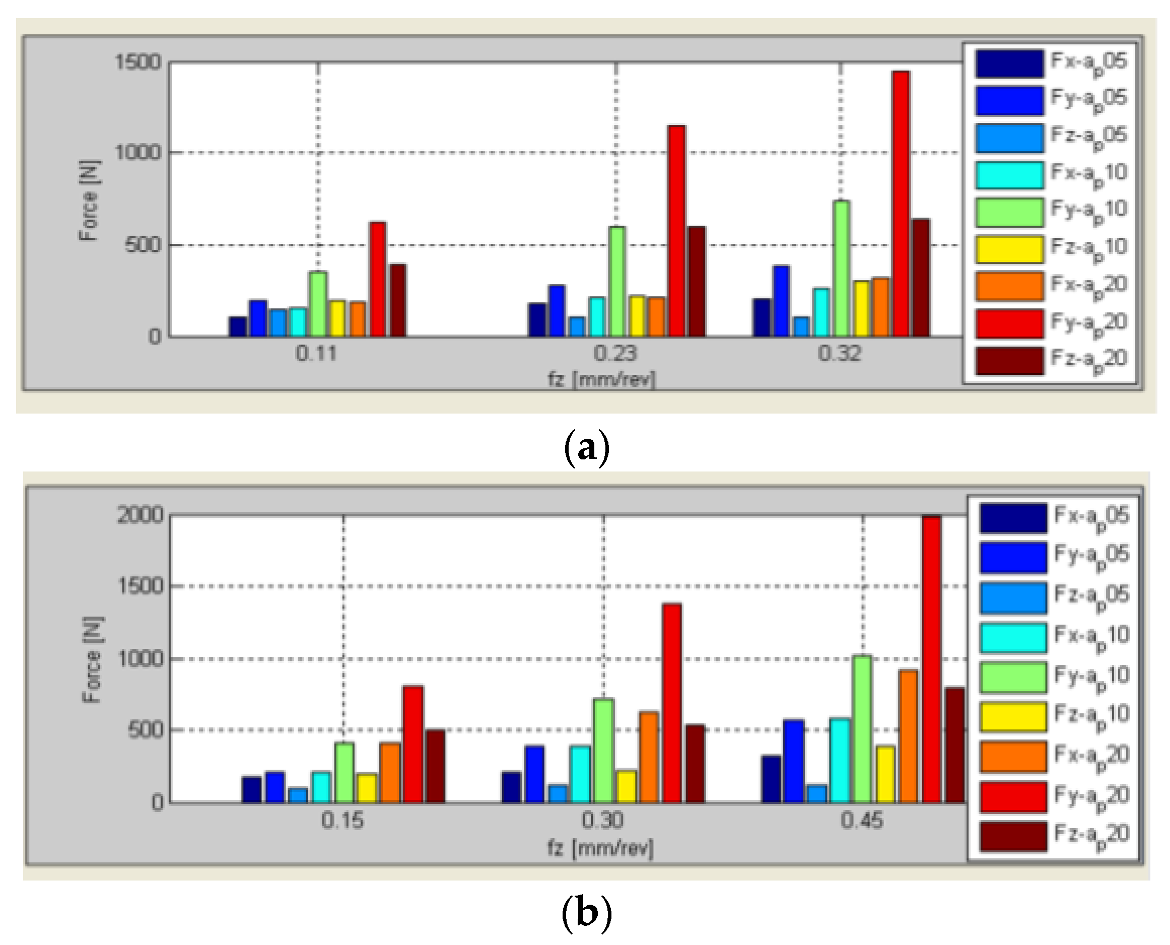
® was used to predict the cutting forces for the different tools, workpiece materials, and cutting conditions.
Figure 8 shows the three Cartesian cutting forces for two typical turning tools, a rhombic 35° insert (standard ISO VBMT) and a square-45° insert (SNMG).
Taking the estimated cutting forces and the experimental stiffness as inputs for the developed software, it was possible to predict the tool tip maximum static deformations and the worst positions in which they were at their maximum.
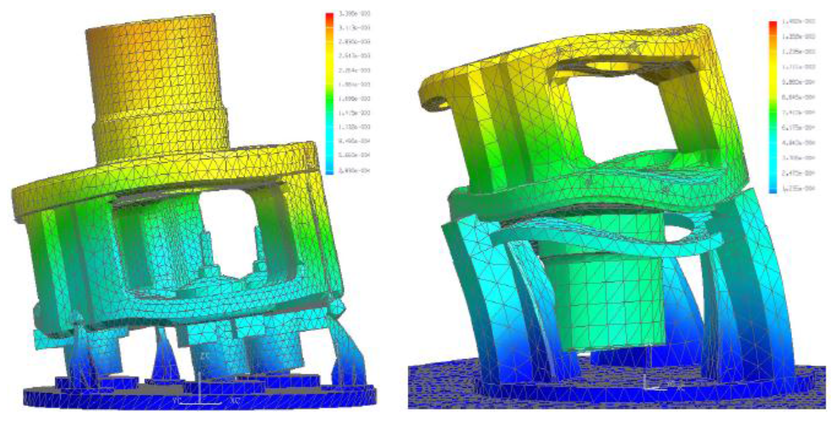
Hence,
Figure 9 shows the deformation of the part-fixture-table assembly under radial forces for two different clampings of the same part, using FEM. The meshing was finer in those areas in which more resolution was demanded. Therefore, after the virtual testing of the proposed designs, it was possible to define the best clamping system.
Fixtures have been designed over the last two years by applying the software.
Nowadays, the estimation of cutting forces is used on a daily basis for the best selection of cutting parameters for all machining operations applied on large diameter parts made in high-strength iron casting. Therefore, the customer here is trending to an exhaustive use of simulation for making decisions about how to apply machining and obtain the optimal process outcome. All the cases are recorded in the software database, to accumulate knowledge.
5.2. Case Study 2: Chatter Free Turning of Large Crankshafts for the Naval Industry
In this case, Dynpro
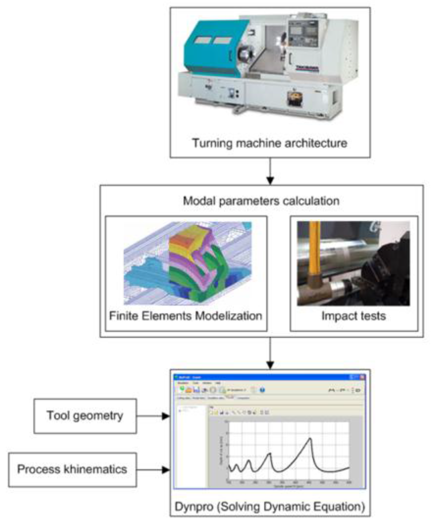
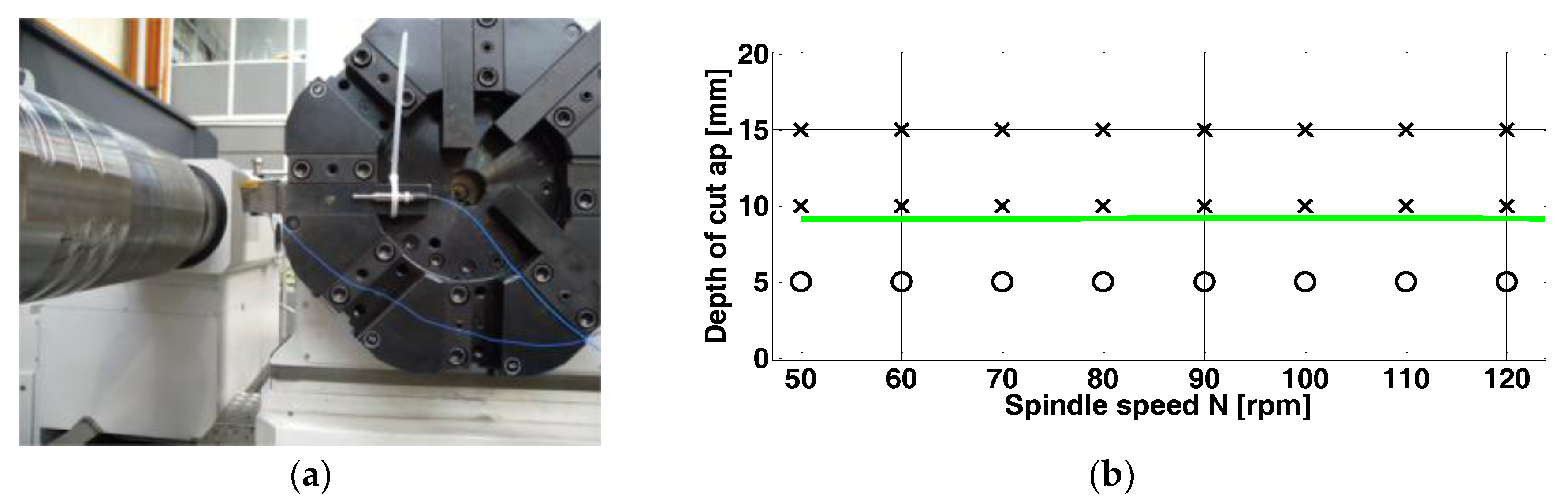
® was used to predict chatter-free zones in the turning of large crankshafts, calculating the stability lobes that can be used for evaluating the best dynamic behavior among different virtual architectures. The selected machine for the model validation was a horizontal lathe. As seen in
Figure 10, the dynamic study of the process was performed following different levels. Firstly, the modal data from the machine tool cutting system was obtained by FEM and hammer impact tests. Secondly, the simulation of the dynamic behavior module simulated the stability limits for an operation typically performed in this machine.
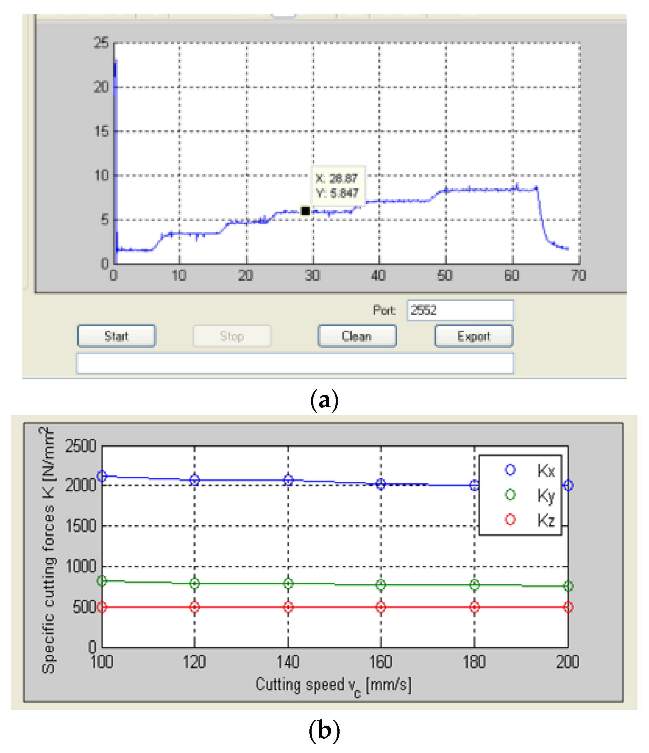
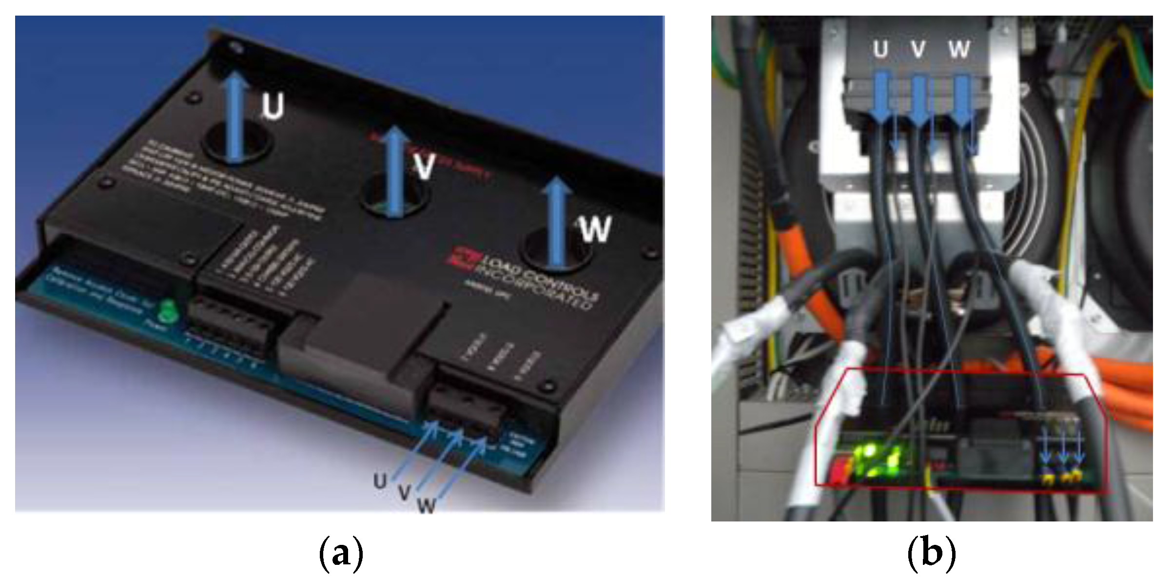
To solve the chatter equation, the specific cutting energy is previously needed. Because of geometrical interferences, a dynamometer was not possible to be adapted in situ. However a power sensor was put to work during the characterization tests (see
Figure 11).
This device takes instantaneous and direct readings from the spindle drive, which are recorded and filtered with Dynpro®. With the power values, the specific cutting coefficients in the Cartesian and tool coordinates were obtained for a rhombic carbide insert (CNMG19) and AISI 1045 steel, resulting in Kt = 2079 MPa, Kr = 775 MPa, and Ka = 533 MPa. It must be noted that this tool is prone to vibration in the axial direction (Z) when performing straight turning operations due to its lead angle (positioned at κr = 95°).
The modal parameters were obtained by hammer impacts and FEM modeling of the machine (
Table 1). First, a mode-to-mode plot was simulated to identify the most limiting modes. Among them, it was noted that
mode 1 of the workpiece and
mode 7 from the tool were the most restrictive, both with a high tendency of vibration in the Z direction.
Figure 12 presents the boundary curve corresponding to those modes acting simultaneously (full plot) against the experimental points from the chatter tests. Stable and chatter cases (respectively with o and x marks) are derived from the signals recorded during cutting by two accelerometers and a microphone.
The cutting signals were then post-processed with the software to identify the sources of vibration. Dynpro
® allows for converting the signals to the FFT spectrum (magnitude vs. frequency) or to the spectrogram (frequency vs. time). It was observed that the machine exhibited (see
Figure 13) high frequency vibration (near 3026 Hz). This was confirmed also by the wavelength of the surface marks.
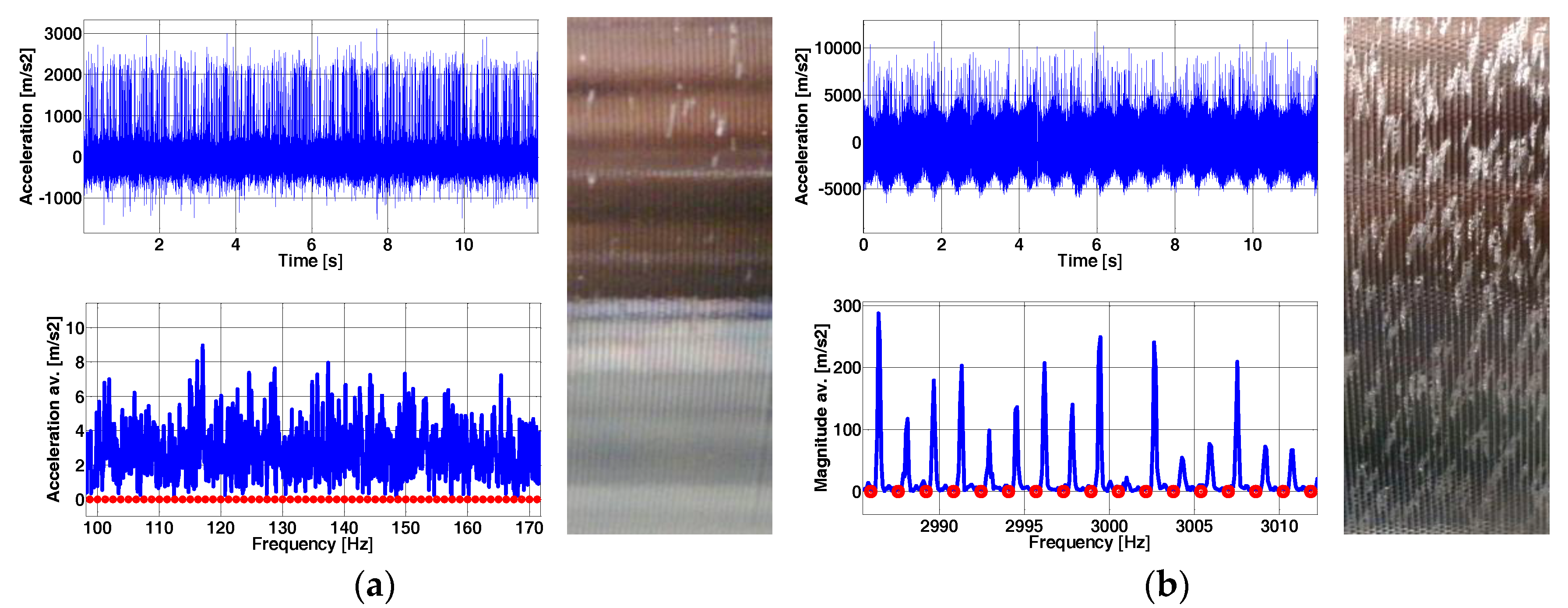
Figure 14a,b show the frequency signals with respect to time, the frequency spectra (FFT), and the final surface finish for the two cases, stable and chatter. The first one leads to a distributed FFT signal in the frequency range with low amplitude peaks while the second one presents a dominant peak near the natural frequency and a phase lag periodic peak pattern with respect to the cutting frequency of the cutting and its multiples (circles in red of
Figure 14b).
Machine designers are using the above approach in the design of machine variations, increasing the number of cases and simulations in the database, and it can reduce 87% of the cases of vibrations on roughing and semi-finishing turning operations.
Finishing operations were not addressed because vibrations never appear at very low depths of cut values in turning.
6. Conclusions
Industrial enterprises demand integrated information systems that can comprise the whole production process of any new product. In the case of companies dedicated to the machining of high-added value parts, or to the manufacturing of machine-tools, this demand is even higher, in view of the increasing customer expectations on the part quality and the competitiveness of this business. Considering that many of the usual machining problems have been solved by the state of art solutions but are not currently applied in daily production, it is crucial to have a reliable utility that can provide the greatest number of solutions in an easy and nimble way, which would be of invaluable help to enterprises in the decision-making process.
This work presents a utility approach that emerged from the university, aimed at closing the lack of process decisions and assistance support in machining companies. Companies are engaged in day-to-day business, thinking more in the short rather than long term.
The utility includes different models that were developed over the last ten years. This simulation utility incorporates not only predictive applications, but also the possibility to interact with the process so as to prepare and work with real cutting signals. In this way, it has an on-line/off-line dual application. It is capable of recording power signals, working with force and noise signals, and adjusting the response functions in frequency (FRF). With all this, this assistant tool involves different company departments for working in a cooperative way: (a) CAM engineers to program the right toolpaths; (b) machine designers for defining the machine configuration; (c) process technicians for the detection and reduction of the vibrations during machining; (d) cutting tool manufacturers for the design of the tools, and others. It also sought to reduce the human factor whenever possible.
In order to prove the capabilities of this program, two successful cases have been shown: a machine tool builder and a manufacturer of components for big gearboxes for the windmill sector. In the former, vibration and chatter conditions were implemented, whereas in the latter, the focus was more on static deformations.


 ,
, 


