Vibration Protection of a Famous Statue against Ambient and Earthquake Excitation Using A Tuned Inerter–Damper


Department of Mechanical Engineering, Politecnico di Milano, 20156 Milan, Italy
*
Author to whom correspondence should be addressed.
Machines 2017, 5(4), 33; https://doi.org/10.3390/machines5040033
Submission received: 24 October 2017
/
Revised: 8 December 2017
/
Accepted: 18 December 2017
/
Published: 20 December 2017
Abstract
:This paper deals with the performance analysis of a vibration-isolation system for Michelangelo Buonarroti’s famous Ronadanini Pietà statue based on the monitoring and analysis of vibration signals. A tuned mass-damper–inerter is introduced in order to increase the effectiveness of the isolator in the horizontal direction. Specifically, a multi-degree-of-freedom (MDOF) model for the system, including non-linear terms, is proposed. The monitoring data of the structure inside the museum were utilized to update the MDOF model of this structure. Then, the effect of different parameters was analysed, and some modifications proposed to enhance the efficiency of the isolation system in its working condition. A combination of tuned mass-dampers (TMD) with an inerter is proposed to attain a considerable increase in the performance of the isolation system based on the main feature of the tuned mass-damper–inerter (TMDI), which can apply high apparent mass to a system without adding considerable real mass to the original system. Various performance functions are used to illustrate the efficiency of the proposed TMDI. It is shown that a significant effect of this passive method is to reduce the level of vibration in the updated model of this sensitive and valuable object.
1. Introduction
Preserving objects of cultural heritage against various sources of vibration such as ambient sources and earthquakes can be important. To this end, different vibration-control strategies have been proposed in literature to protect these types of objects and structures. Among different proposed methods, the tuned mass-damper (TMD) is a widely used methodology in different applications. The design details of this element for a single degree of freedom (SDOF) was comprehensively introduced by Den Hartog [1]. The main limitation of TMDs is the maximum mass which can be added to the main structure. In fact, in many applications it is not possible to use TMD with a proper mass in order to dissipate the energy of unwanted vibration. In 2002, a new mechanical element named an inerter was introduced by Smith [2]. In fact, the inerter is the counterpart of a capacitor in mechanical systems. This element has two terminals and can provide a force proportional to the relative acceleration between the two terminals. Introducing inerters to mechanical systems can provide an apparent system mass without adding considerable mass to the original system.
There has been intensive research into the application of TMDs in different practical systems. In addition, finding the optimal parameters of TMDs is a topic that has received interest in various studies. The application of inerters with different configurations to control vibrations in various structures has been studied in recent years; see for instance Scheibe [3], Wang [4] and [5], Hu [6], Chen [7,8,9], Brzeski [10] and Shen [11]. The combination of an inerter with a TMD to add apparent mass to the passive element has been investigated by Marian et al. in [12] and the optimal parameters of the passive element are computed using a numerical solution. Li et al. [13] introduced an adaptive inerter to enhance the performance of the suspension system of a quarter-car model. An adjustable model of inerter has been proposed in parallel with a spring and damper in the model. Salvi et al. in [14,15] studied the optimal design parameters, including frequency ratio and damping factors in SDOF by using analytical and numerical methods and considering various types of excitation. Tubino et al. [16] designed an appropriate TMD to mitigate the pedestrian-induced vibration on a bridge. Matta et al. [17] designed a control for mass-uncertain rolling pendulum TMDs in order to reduce the vibration of buildings induced by seismic excitation. Liu et al. [18] introduced a novel method for passive vibration isolation in the low frequency range by combination of a lever-type isolator and X-shape supporting structure.
Arfiadi et al. [19] evaluated the optimum properties and placement of TMDs for vibration control in buildings by using a genetic algorithm (GA). Other research to design the optimum control of vibration for tall buildings based on the GA has been conducted by Shayeghi et al. [20]. Furthermore, Mohebbi et al. [21] obtained the optimal parameters of multiple tuned mass-dampers (MTMDs) using the GA method for a structure subjected to seismic excitation. Morga et al. [22] investigated the reduction of vibration induced by wind load using a TMD in a slender structure. Moreover, the tuning frequency is optimized based on displacement and acceleration of the top end of the structure. In other research, Si et al. in [23] proposed TMDs for passive vibration control in a spar-type floating wind turbine. The authors represented the optimum values for the parameters of the TMD by considering different performance indices and using different optimization methods. A gradient-based method has been used by Li et al. [24] for optimizing distributed multiple tuned mass-dampers. The proposed method can be utilized in the situation that there are uncertainties in parameters of the structure and TMDs. Zuo and Nayfeh [25] considered multi-degree-of-freedom (MDOF) systems with MDOF models for absorbers, and proposed an approach based on the descent sub-gradient method to optimize the parameters of tuned mass-dampers. The results have been evaluated experimentally. Groco et al. [26] studied the robust optimum design of TMDs installed on a MDOF system under stochastic seismic input disturbances by assuming uncertainties for the structural model parameters.
In the field of semi-active and active vibration control, there are some interesting results targeting vibration reduction in buildings and large-scale structures that they can be found in [27,28,29,30,31]. The concept of such work can be extended for some structures such as tall and slender statues. In [32], semi-active TMDs were installed to mitigate wind-induced vibrations in the Volgograd Bridge. Experimental and numerical investigations demonstrated that the first three bending modes are susceptible to wind excitation. Therefore, a high efficiency of semi-active TMDs over a wide frequency range was required. This system is able to mitigate vibrations within the frequency range of all three bending modes, like passive TMDs, with twice as much mass. Based on the results, this semi-active TMD concept also helps to reduce the passive mass. Chen et al. [33] compared different combinations of passive, semi-active and active inerters and dampers for vehicle suspension. Based on their results, semi-active inerters and semi-active dampers resulted in the best performance. A physical realization of a semi-active inerter has been introduced in [34]. The proposed semi-active device has been obtained by replacing the flywheel in a ball-screw type inerter with a controllable-inertia flywheel. The performance of the proposed method has been demonstrated through experimental results.
Due to proportionality of the produced force of the inerter element to the acceleration of mass, this element can be added easily to the equation of motion of the physical system and its constant appears in the mass matrix [35]. A tuned mass-damper–inerter (TMDI) solution has been numerically investigated to illustrate the performance enhancement of the isolation system of Michelangelo Buonarroti’s famous Rondanini Pietà statue in the vertical direction. It should be noted that this isolation system can protect the main structure in two orthogonal directions. The authors have presented the optimum parameters of the proposed TMDIs in [36]. Two different optimization methods were used in order to obtain the optimal parameters. In the work, the updated multi-degree-of-freedom (MDOF) model is presented based on the results of the experimental tests mentioned in [37].
The main contribution of this research is, first, aimed at developing a MDOF model for the isolation system of the famous statue, based on the monitoring results taken from this structure in the new location; then, a second purpose is to use this updated model to apply TMDIs to increase the performance of the isolation system against ambient vibrations. The isolator consists of sliding elements and rubber-bearing elements, and its performance needs to be improved, according to experimental tests which have been previously carried out [35]. In this work, the MDOF model of both the isolation system and the statue has been obtained, based on the results of continuous monitoring of the real structure. Friction and non-linear dissipating forces for the sliding part have been considered for this MDOF model. The passive control device that has been designed can provide a significant reduction of the amplitude level of the frequency response functions (FRFs) of the updated MDOF model of the structure.
It should be noted that the main difference between this study and the previous one [36] is to consider a MDOF model for the isolator that is updated based on the monitoring results and to focus on the results of this model in the horizontal direction. The previous work included the results of the laboratory tests that had been performed on a full-scale copy of the statue, whereas this new model consists of parameters that are updated using the data of the working condition of the isolator in the museum. In addition, in this study the performance of the isolation system in the horizontal direction will be examined, which was not considered in the previous research. This study addresses the performance of the isolator against ambient vibrations and earthquakes.
The rest of this paper is organized as follows. In Section 2, the monitoring results of the structure are presented. In Section 3, the equation of motion of the actual isolation system is explained in brief. Based on the monitoring results, the parameters of the 5DOF model describing the isolation system will be updated. In addition, the effect of some parameters will be checked against the results of the 5DOF model. Section 4 is about using tuned mass-damper–inerters (TMDIs) to reduce the level of vibration in the horizontal direction. Using various indices, the impact of different values of the TMDIs’ parameters is presented in this section. Furthermore, the response of the updated model equipped with the TMDIs to a recorded earthquake will be checked. In Section 5, the effect of considering uncertainties associated with the structural parameters of the isolation system will be evaluated and the robustness of the control method with regard to the uncertainties identified will be checked. Conclusions are presented in Section 6.
Notation:
The superscript ‘T’ denotes matrix transposition; shows the n-dimensional Euclidean space; means a block diagonal matrix; indicates the minimum value of with respect to . In addition, and are adopted as first and second derivatives of vector with respect to time, respectively. denotes the norm of a vector.
2. Monitoring the Statue Inside the Museum
In this section, the results of vibration monitoring of the isolation system are presented. The statue and the isolator are part of the new exhibition inside a museum at Castello Sforzesco, in the center of Milan. The isolation system consists of two parts: the first is a sliding unit for mitigation of the seismic vibrations; these low-friction slides are equipped with devices to restore the statue to its initial position in case of displacement from the rest position. The second part consists of a vibration mechanical filter, placed on top of the sliding unit, made up of anti-vibration rubbers for isolating ground-borne vibrations generated by the underground trains. It should be noted that the sliding part is made up of two orthogonal low-friction linear motion bearings, allowing displacement of the system in the horizontal direction. The restoring function is provided by a rubber belt connecting the sliding plate. This sliding unit was designed to respond to excitations induced by an earthquake lower than 2 mm/s. To avoid undesired movement of the base and statue in the absence of an earthquake, the belts of the sliding unit have been pre-loaded. Therefore, no relative movements occur if the applied force is lower than 500 N.
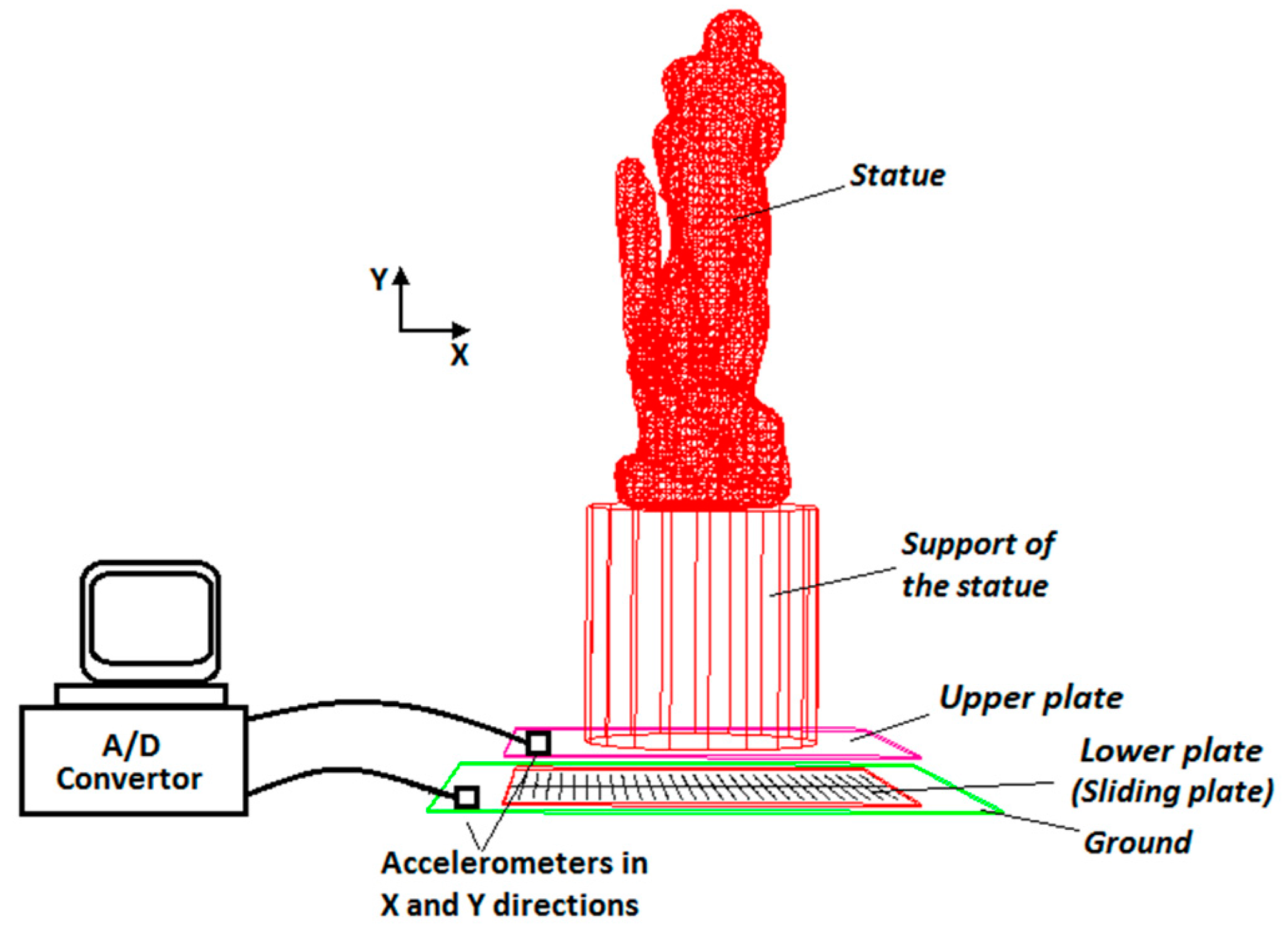
Vibrations of this structure and of the floor are continuously monitored in the new location. In fact, four accelerometers measuring in the horizontal and vertical directions are located inside the isolation system on the upper plate (i.e., the plate rigidly connected to the lower part of the support of the statue) and at the ground level. In Figure 1 the schematic figure of the monitoring system and the sensor positions are presented. Figure 2 shows the positions of the accelerometers on the isolation system. Two accelerometers are used to measure the vibration along the y (vertical) and x (horizontal) directions at the upper plate. In addition, ground vibration is measured by two accelerometers fixed along the same vertical and horizontal directions. Data are acquired continuously 24 h a day and stored every 10 min. In Table 1, the specifications for the sensors and the acquisition system are presented.
In Figure 3a, a measurement sample in the horizontal and vertical directions for a 10-min time record is plotted. It should be noted that each train passing by is clearly seen as an increase in the vibration peaks in the responses shown in Figure 3. This figure shows the vibration level in the vertical direction is higher than in the horizontal direction (around 2 times). It can be noted that the museum is located near the train and subway stations and it is one of the reasons for monitoring this structure. Results in different measured times have been used in order to estimate the averaged FRFs between the floor and the base.
According to the measurements, the FRFs in the horizontal and vertical directions have been obtained by averaging complex values in the frequency domain. These FRFs are presented in Figure 4. The result in the vertical direction shows that the first natural frequency is about 9.4 Hz, which is relatively close to the results of the laboratory test. The FRF obtained for the horizontal direction is different from the results of the laboratory test. The results of the laboratory test have been plotted by red dashed lines in Figure 4. It should be noted the laboratory test has been carried out on a big shaker and by using a full-scale copy of the statue (for more information, please refer to Cigada et al. [35] and Siami et al. [36]). Therefore, we need to update our previous MDOF model considering the obtained results obtained from the monitoring system installed at the museum. The FRFs express a high level of vibration transmitted to the structure in the x-direction of about and, in the case of the vertical direction, 9.4 Hz.
3. Model Description and Parameter-Sensitivity Analysis
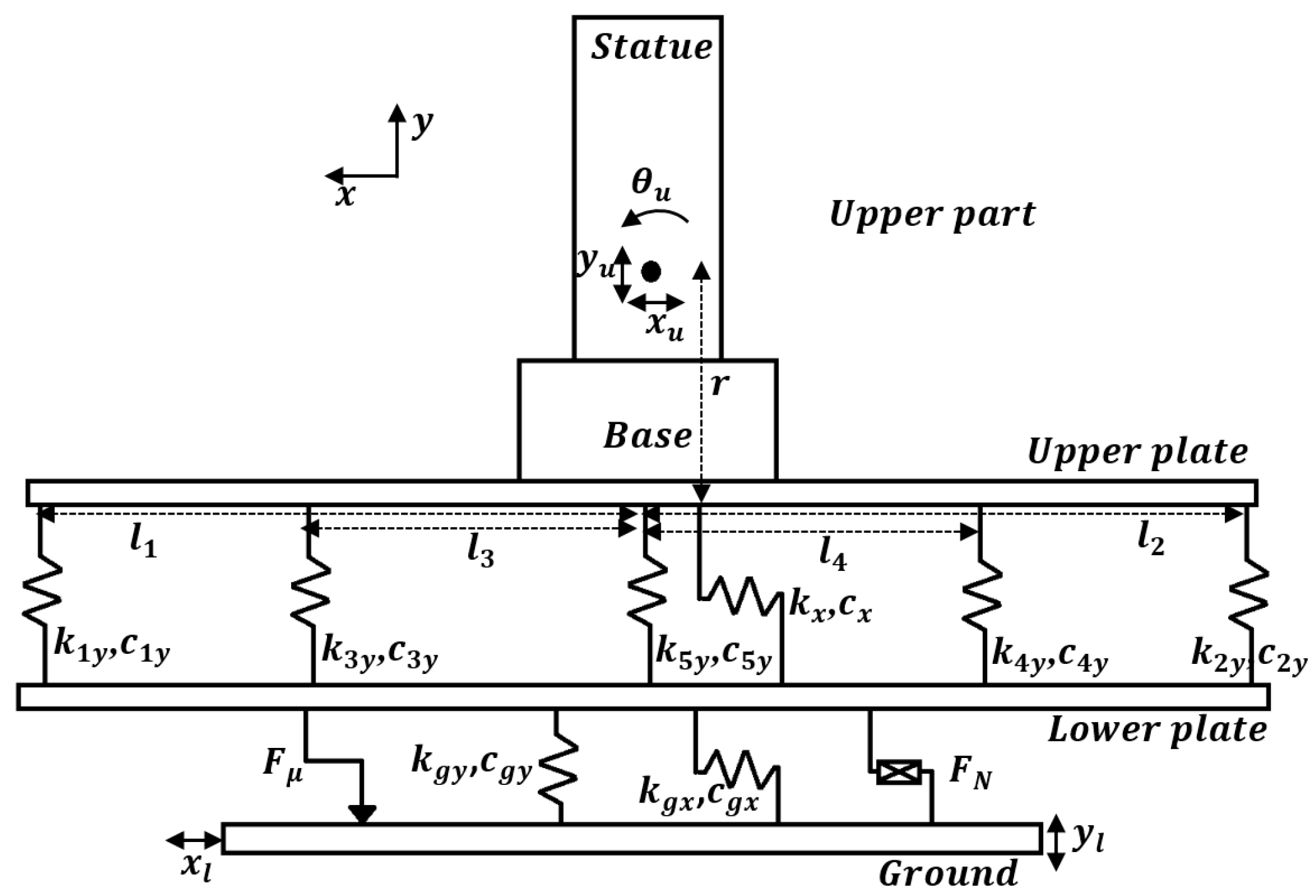
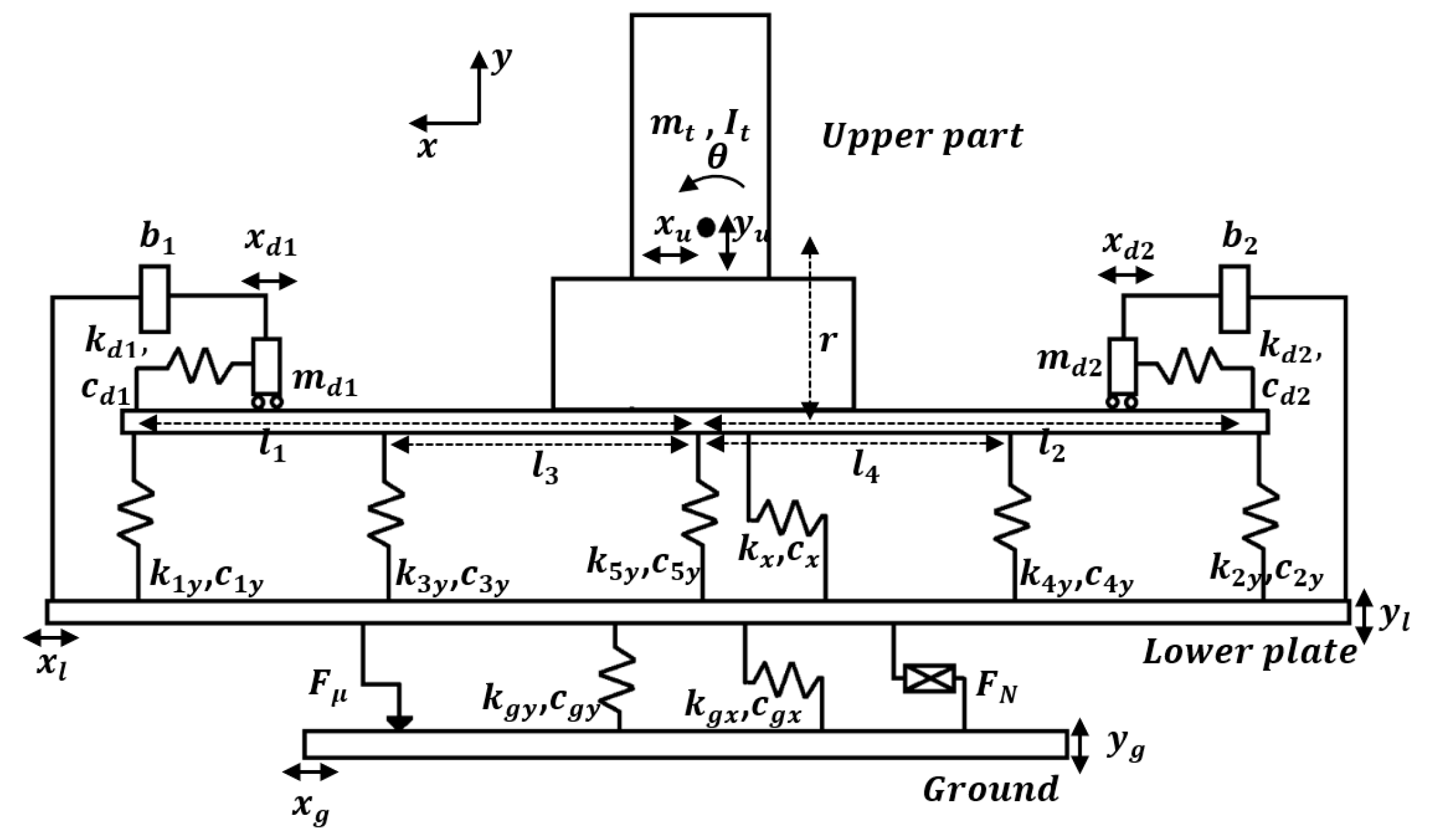
In the previous research, a 5DOF model for the isolation system has been introduced and its parameters have been updated using a laboratory test. Because the FRF obtained in the horizontal direction from the monitoring system has some differences compared with the results of the laboratory test, the parameters of the 5DOF model should be updated using the new result. For this purpose, first this 5DOF model is introduced briefly, and then the updated parameters will be expressed. The schematic figure of this 5DOF model is shown in Figure 5. The general equation of motion for this model can be written as:
and where , and are mass, damping and stiffness matrices, respectively; and , and are the center of mass translation of the upper part along the x and y directions and the rotation of the upper part around the center of mass, respectively. In addition, and are the displacements of the lower plate in the x and y directions, respectively; is the disturbance transmitted from the ground to the lower plate; is the friction between the ground plate and lower plate; indicates the non-linear dissipating force. Details about the matrices and vectors can be found in [32,33]. The dissipative force is a non-linear function of the sliding speed between the lower and the ground plates, as depicted in the following form:
where is the number of restoring elements; and are the damping coefficient [] and relative velocity [], respectively; and is a coefficient which, in the present case, is equal to . Based on the information provided by the manufacturer of the sliding unit, n is equal to 4 and the value of is . Therefore, can be represented in the following form:
It should be noted the expression for the friction force in Equation (1) is presented as:
where and are, respectively, the velocity of the lower plate and the ground plate along the x direction, is the static friction coefficient between the lower and ground plates, is the difference between the maximum friction coefficient and the dynamic friction coefficient, is a constant, and is the force normal to the friction surface.
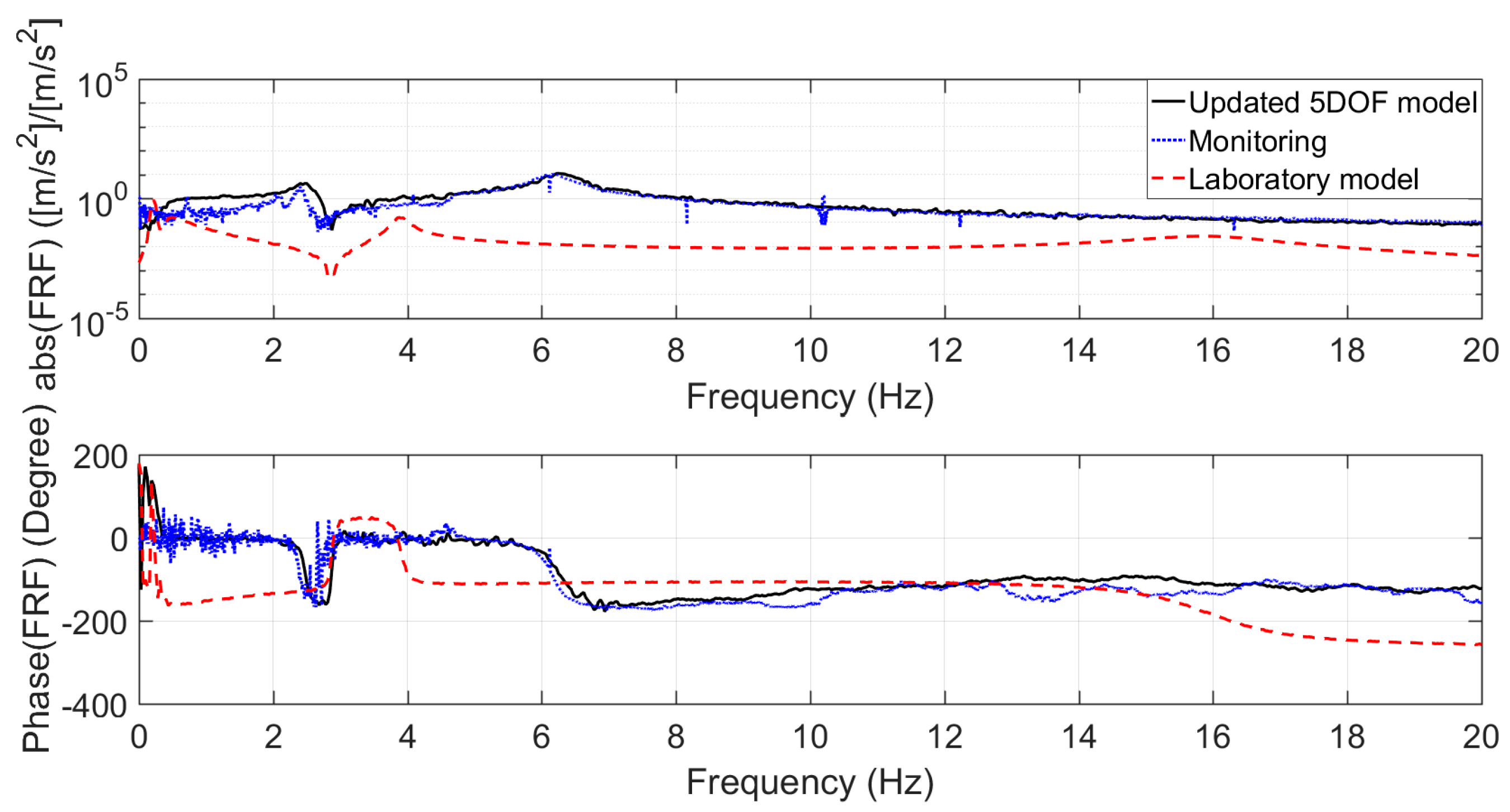
The parameters of the mentioned 5DOF model have been updated in order to have similar FRFs for the corresponding points in the model and those which have been obtained from the vibration monitoring. The new values are presented in Table 2. These new parameters will be used for the next analyses in this research. Considering the values presented in Table 2 for the updated 5DOF system, the FRFs comparison for the horizontal and vertical directions is plotted in Figure 6 and Figure 7. The FRFs obtained from the measured accelerations are superimposed on the numerical ones, in the same plots, in order to compare the results. In addition, the FRFs of the model before updating using the monitoring results have been presented and this is named the laboratory model. The parameters of the older model (the laboratory model) had been tuned based on the results of experiments performed in the laboratory test. These plots illustrate good correlations between the results of the updated model and the vibration monitoring. This new model can be used to simulate any possible performance improvement for the isolation system inside the museum, adopting true operational conditions as the input.
Here, the effect of some parameters on the performance of the isolation system will be examined. One of the elements that is being investigated during the laboratory test is the effect of the belts of the sliding unit which was introduced in Section 2. For the updated 5DOF model using the results of the monitoring system, the value of this non-linear force has been set to zero. This means that under usual operational conditions this force does not act on the lower plate. In other words, the passage of a train causes null displacement on the sliding unit so we cannot see the effects of the rubber belts on the dynamic behavior of the isolation system. If we apply this dissipating force also in the case of vibrations due to the train’s passage, we can see a significant reduction in the level of vibration in the x direction. This means that the damping model is not fit to reproduce reality at very low or even null displacements, being the result of interpolations needed to reproduce the right behavior for higher amplitudes. This strategy is illustrated by using the updated 5DOF model. The FRF between the ground plate and upper plate when the non-linear dissipating force is present in the system is plotted in Figure 8. In addition, the FRF between the ground plate and the statue head is presented.
The other parameter that affects the results is the friction coefficient of the sliding unit. The FRFs for the updated model, thanks to the results from the monitoring and with a higher friction coefficient, have been plotted in Figure 9. It can be observed that the value calculated for the updated model () provides a higher level FRF for the upper plate.
4. The Equations of Motion of the Isolation System with TMDI
The equations of motion of the isolation system equipped with the tuned mass-damper and inerter is presented in this part. First, the inerter and a type of mechanism for this device will be explained briefly. An inerter is a mechanical element that can be used in a structure in order to apply apparent mass to the system. This element was introduced in 2002 [2] and it has been used in vehicle-suspension systems to increase the performance of the isolation systems. A schematic configuration of an inerter is shown in Figure 10. The force between two terminals can be presented as:
where is the force applied on each terminal; and is the inertance with mass units (). The velocity of terminals 1 and 2 are presented by and , respectively, and represents derivation of variable with respect to time. This type of the inerter is called a ball-screw type and its inertance can be defined as:
where is the pitch of the ball-screw assembly; and are the applied force on the terminals and the reaction torque on the screw, respectively; is the angular velocity of the screw; and is the mass moment of inertia of the ball-screw inerter.
In this part, two inerters have been added to the two TMDs, installed on the upper plate. A schematic figure of the isolation system with two TMDIs in the horizontal direction has been plotted in Figure 11. The equation of motion of the isolator system can be presented as follows:
and
where , and are the mass, stiffness and damping matrices of the 7DOF system, respectively; and and indicate the displacement of two TMDIs in the x direction. The input vibrations in the horizontal and vertical directions are and , respectively. Matrices and vectors of the system have been expressed in Appendix A.
Now, based on the good correlation between our original MDOF model and the experimental test results, we can verify the effect of the TMDI on the isolation system and obtain an effective and practical passive method for improving the performance of the vibration-control system. The values that have been chosen for the TMDIs’ parameters are presented in Table 3. Two different tuning frequencies () and two damping factors () have been considered for these cases. These two frequencies have been chosen according to the peaks that exist in the FRF presented in Figure 4 in the horizontal direction. For the inertance of the system (), two possible solutions have been assumed. These values have been considered based on a type of inerter that will be manufactured for the next steps in this research. In addition, the damping coefficients have been chosen based on the optimum values obtained for the TMDIs in the vertical direction in the previous research [36].
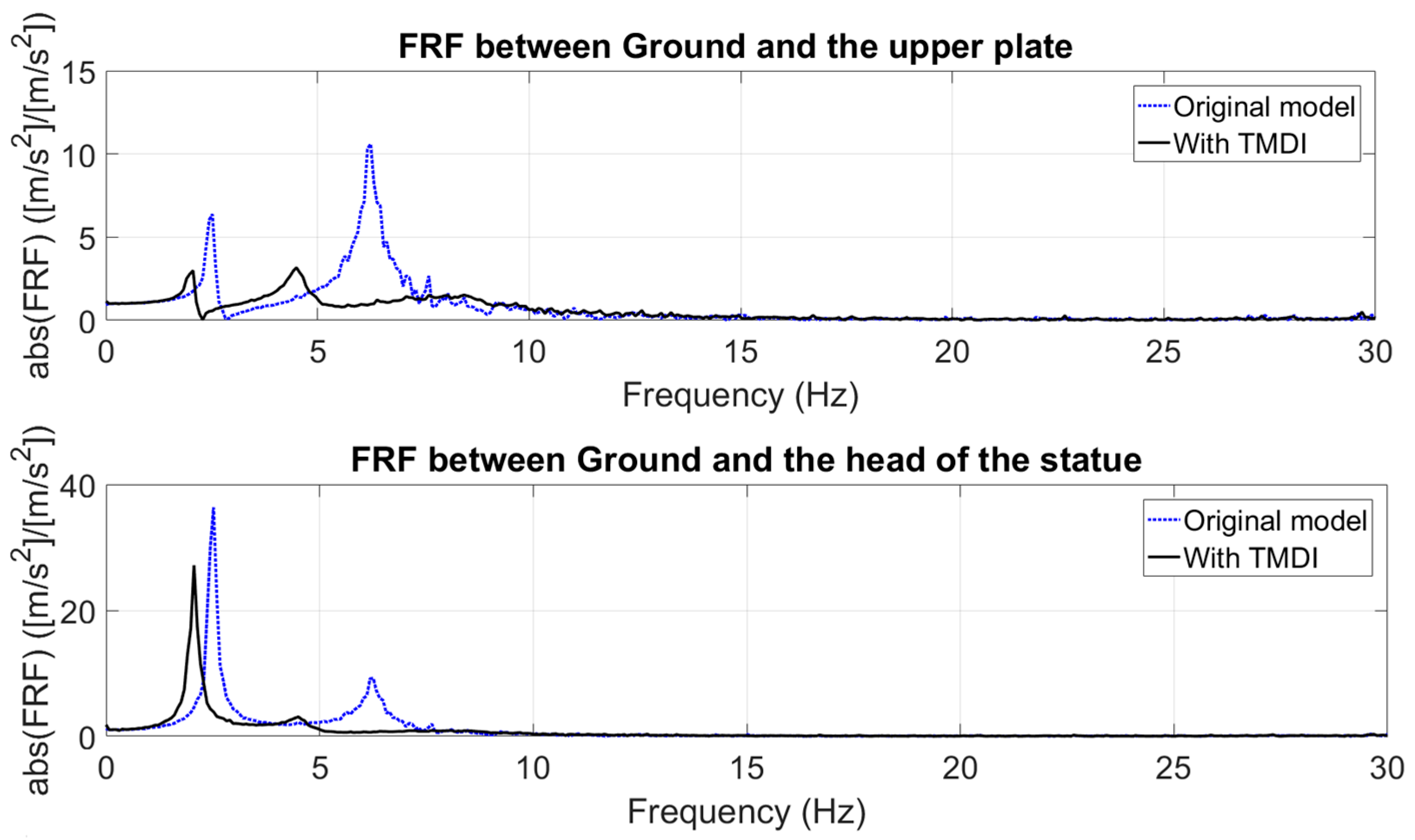
Considering the values given in Table 3, the FRFs between the ground plate and the upper plate and the head point have been plotted in Figure 12, Figure 13 and Figure 14. Based on these results, it becomes clear that tuning on the second peak (), provides significant reduction in this area, as expected (Figure 12). On the other hand, choosing a tuning frequency around the first peak (. ) can cause a proper reduction in the second peak and, simultaneously, we can see the positive effect around the first peak of the head point. It should be noted, in the case of an uncontrolled structure, that the vibration level around the first and lower resonance peaks for the statue head is clearly evident. Choosing a tuning frequency around the first peak () and using higher inertance and higher damping can cause significant reduction for both peaks.
For a better comparison of the response of the isolation system, three different indices have been used, as follows [37]:
where is a given finite time; and , , and are the vertical acceleration of the upper plate, the displacement of the upper plate, lower plate and ground plate (rigidly fixed to the ground), respectively. The other index that it is used here is the maximum peak value of the FRF function, that can be defined as:
where is the frequency-response function of the MDOF system for input and output. These indices help us to have a better insight into the impact of the TMDI parameters on the performance of the isolation system. In Table 4, the values of these indices for different cases are presented. It can be seen that the index of acceleration of the upper part () in the case of the TMDIs being used is strongly reduced if compared to the uncontrolled case. In addition, in different cases shows that the acceleration of the lower plate is not increased because of using the TMDIs. The maximum value of the FRF between the ground plate and the upper plate () in this table shows considerable reductions for the cases in which TMDIs has been introduced to the isolation system.
It should be noted that the advantage of using a TMD equipped with an inerter is to prevent a high amount of added mass being applied to the isolation system. The level of added mass will change the natural frequencies of the isolation system in both directions. In addition, adding this amount of mass to the compact system will be difficult in practical terms. In the presence of a TMDI, by introducing a small amount of mass to the upper plate a high level of apparent mass due to the inerter is accessible for the absorbers.
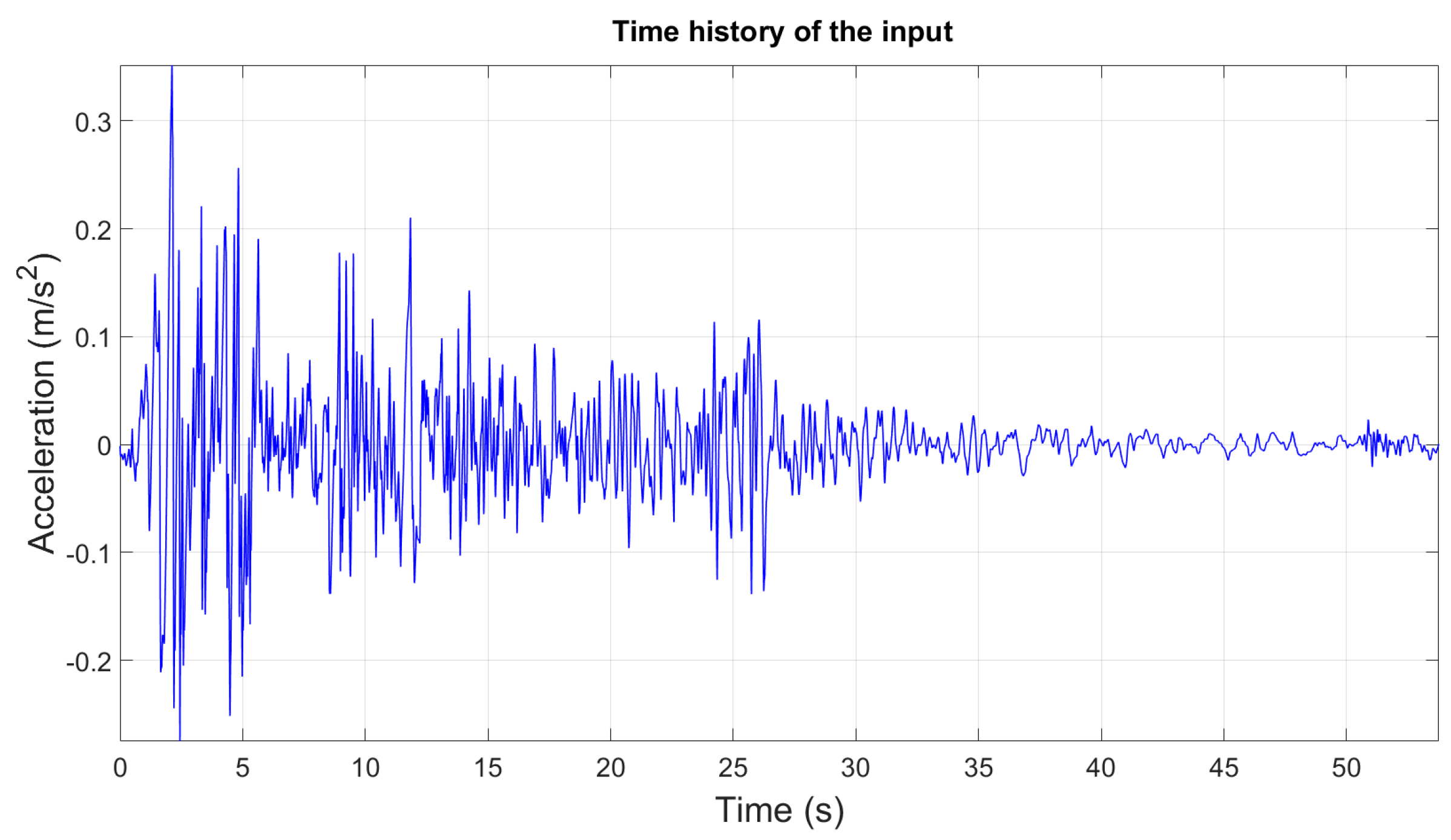
Here, the response of the model to the famous earthquake, North–South 1940 El Centro, has been evaluated. Figure 15 shows the time history of the earthquake in terms of measured acceleration. The response of the updated model to the disturbance for two cases according to Table 3 have been presented in Figure 16 and Figure 17. These figures illustrate the efficiency of the TMDIs in the presence of earthquake excitation. The FRFs have been presented between the ground plate and the upper plate and between the ground plate and the head point for each case (cases 1 and 2). In all cases, the amplitude level of the FRFs has decreased considerably.
5. Robustness Analysis with Respect to Parameter Uncertainties
In the previous section, we checked the effect of using TMDIs by considering nominal values for the parameters of the isolation system. Here, uncertainties are considered and introduced for both the damping and the stiffness of the isolator. This deviation from nominal values occurs because of variations in material behavior under real working conditions or due to any defect in the isolator’s rubber bearings. The damping and stiffness matrices, including the uncertainties, can be represented as follows:
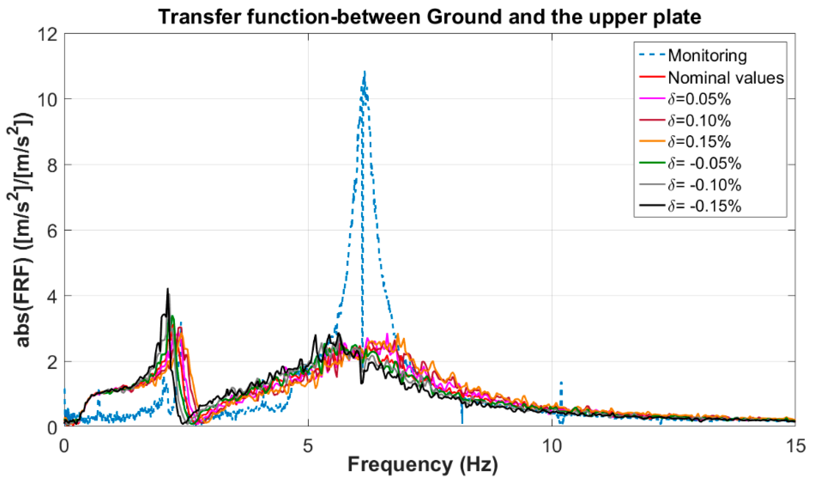
where , are the nominal values of the isolation damping and stiffness matrices, respectively; , indicate the amount of uncertainty in damping and stiffness, respectively; is the damping matrix including uncertainty and stands for the stiffness matrix with its uncertainty. The assumed values for stiffness and damping of the elements have been listed in Table 5. Uncertainties of , and are assumed for this study. It should be noted that the equal amount of uncertainty has been assigned to both damping and stiffness of the elements in each solution (). The results of this evaluation are presented in the following figures. In Figure 18 the effect of different percentage on uncertainties in the damping and stiffness matrices on two indices have been presented for the upper plate. According to these plots, it becomes clear, even in the maximum deviation of the indices that occurred in a higher uncertainties percentage (), the TMDI can be effective according to the results presented in Figure 19. In this figure, it can be observed for the minimum values considered for the structural parameters that the passive method can be effective in reducing the level of vibration in comparison with the monitored structure with no controls. Based on the results, the TMDIs used for this application have sufficient robustness under the uncertainties considered for damping and stiffness of the isolator.
6. Conclusions
In this paper, the dynamic performance of the isolation system for the famous statue of Michelangelo was investigated based on the results of vibration monitoring of this structure inside the museum. The FRFs obtained from the monitoring system demonstrated a high-level of vibration on the upper plate in both horizontal and vertical directions. It was shown that the behavior of this system in the vertical direction is similar to previous tests on the 1:1 scale model of the structure in the laboratory (see [35]). The effects of different parameters on the response of the isolation system in the horizontal direction have been investigated. This study showed the non-linear dissipating force of the sliding unit does not act on the system in the operational condition and in the presence of the ambient vibration.
The other solution for vibration reduction in the horizontal direction is to introduce the TMDIs to the 5DOF model of this system. Previously, based on the laboratory test, using TMDIs for the vertical direction has been proposed (for more details please refer to [37]). Using inerters for protecting this valuable object can be a practical and effective way for vibration control without requiring significant modification of the original isolation system. Various cases with different chosen values for the parameters have been used in the horizontal direction, and by checking the FRF between the ground plate and upper part of the statue the efficiency of this method for reducing the vibration transmitted to the statue has been illustrated. In addition, the effect of different cases on the vibration of the structure has been evaluated by using various indices. These indices prove the effectiveness of using this passive element in order to reduce the level of vibration transmitted to the valuable statue. Furthermore, the response of the updated model to the El Centro earthquake with and without the TMDIs has been presented. Based on these results, the efficiency of the proposed method in the case of an earthquake has been illustrated.
For future work, the focus will be on the experimental implementation of the proposed method to a scaled model of the isolation system and the statue.
Acknowledgments
The authors gratefully acknowledge Claudio Salsi and Giovanna Mori (Direction of Castello Sforzesco in Milan, Italy) and Elisabetta Giani (Istituto Superiore per la Conservazione ed il Restauro, Italian Ministry of Cultural Heritage) for the support given to the project on the protection of the Rondanini Pietà against seismic and ambient vibrations.
Author Contributions
A.C. and E.Z. have designed and carried out the experimental tests and validation. H.R.K. and A.S. have proposed the control scheme and developed the analytical model. The remaining part of the work has been done together.
Conflicts of Interest
The authors declare no conflict of interest.
Appendix A
The matrices of the 7DOF model with two TMDIs in the horizontal direction
where
where
and the term can be expressed as:
References
- Den Hartog, J.P. Mechanical Vibrations, 4th ed.; McGraw-Hill Book Company: New York, NY, USA, 1956. [Google Scholar]
- Smith, M.C. Synthesis of mechanical networks: The Inerter. IEEE Trans. Autom. Control 2002, 47, 1648–1662. [Google Scholar] [CrossRef]
- Scheibe, F.; Smith, M.C. Analytical solutions for optimal ride comfort and tyre grip for passive vehicle suspensions. Veh. Syst. Dyn. 2009, 47, 1229–1252. [Google Scholar] [CrossRef]
- Wang, F.C.; Chan, H.A. Vehicle suspensions with a mechatronic network strut. Veh. Syst. Dyn. 2011, 49, 811–830. [Google Scholar] [CrossRef]
- Wang, F.C.; Hsieh, M.R.; Chen, H.J. Stability and performance analysis of a full-train system with inerters. Veh. Syst. Dyn. 2012, 50, 545–571. [Google Scholar] [CrossRef]
- Hu, Y.; Chen, M.Z.Q.; Shu, Z. Passive vehicle suspensions employing inerters with multiple performance requirements. J. Sound Vib. 2014, 333, 2212–2225. [Google Scholar] [CrossRef] [Green Version]
- Chen, M.Z.Q.; Hu, Y.; Li, C.; Chen, G. Semi-active suspension with semi-active inerter and semi-active damper. In Proceedings of the 19th World Congress of the International Federation of Automatic Control, Cape Town, South Africa, 24–29 August 2014. [Google Scholar]
- Chen, M.Z.Q.; Hu, Y.; Huang, L.; Chen, G. Influence of inerter on natural frequencies of vibration systems. J. Sound Vib. 2014, 333, 1874–1887. [Google Scholar] [CrossRef] [Green Version]
- Hu, Y.; Chen, M.Z.Q. Performance evaluation for inerter-based dynamic vibration absorbers. Int. J. Mech. Sci. 2015, 99, 297–307. [Google Scholar] [CrossRef] [Green Version]
- Brzeski, P.; Pavlovskaia, E.; Kapitaniak, T.; Perlikowski, P. The application of inerter in tuned mass absorber. Int. J. Non-Linear Mech. 2015, 70, 20–29. [Google Scholar] [CrossRef]
- Shen, Y.; Chen, L.; Yang, X.; Shi, D.; Yang, J. Improved design of dynamic vibration absorber by using the inerter and its application in vehicle suspension. J. Sound Vib. 2016, 361, 148–158. [Google Scholar] [CrossRef]
- Li, P.; Lam, J.; Cheung, K.C. Control of vehicle suspension using an adaptive inerter. J. Autom. Eng. 2014, 229, 1934–1943. [Google Scholar] [CrossRef]
- Marian, L.; Giaralis, A. Optimal design of a novel tuned mass-damper-inerter(TMDI) passive vibration control configuration for stochastically support-excited structural systems. Probab. Eng. Mech. 2014, 38, 156–164. [Google Scholar] [CrossRef]
- Salvi, J.; Rizzi, E. Minimax optimization of tuned mass dampers under seismic excitation. In Proceedings of the 8th International Conference on Structural Dynamics, Leuven, Belgium, 4–6 July 2011; pp. 1892–1899. [Google Scholar]
- Salvi, J.; Rizzi, E. A numerical approach towards best tuning of Tuned Mass Dampers. In Proceedings of the International Conferences on Noise and Vibration Engineering, Leuven, Belgium, 17–19 September 2012; pp. 2419–2434. [Google Scholar]
- Tubino, F.; Piccardo, G. Tuned Mass Damper optimization for the mitigation of human-induced vibrations of pedestrian bridges. Meccanica 2014, 50, 809–824. [Google Scholar] [CrossRef]
- Matta, E.; DeStefano, A. Robust design of mass-uncertain rolling-pendulum TMDs for the seismic protection of buildings. Mech. Syst. Signal Process. 2009, 23, 127–147. [Google Scholar] [CrossRef]
- Liu, C.; Jing, X.; Chen, Z. Band stop vibration suppression using a passive X-shape structured lever-type isolation system. Mech. Syst. Signal Process. 2016, 68–69, 342–353. [Google Scholar] [CrossRef]
- Arfiadi, Y.; Hafi, M.N.S. Optimum placement and properties of tuned mass dampers using hybrid genetic algorithms. Int. J. Optim. Civ. Eng. 2011, 1, 167–187. [Google Scholar]
- Shayeghi, A.; Kalasar, H.E.; Shayeghi, H. Seismic Control of Tall Building Using a New Optimum Controller Based on GA. Int. J. Civ. Environ. Struct. Constr. Archit. Eng. 2009, 3, 317–324. [Google Scholar]
- Mohebbi, M.; Shakeri, K.; Ghanbarpou, Y.; Majzoub, H. Designing optimal multiple tuned mass dampers using genetic algorithms (GAs) for mitigating the seismic response of structures. J. Vib. Control 2012, 19, 605–625. [Google Scholar] [CrossRef]
- Morga, M.; Marano, G.C. Optimization criteria of TMD to reduce vibrations generated by the wind in a slender structure. J. Vib. Control 2014, 20, 2404–2416. [Google Scholar] [CrossRef]
- Si, Y.; Karimi, H.R.; Gao, H. Modelling and optimization of a passive structural control design for a spar-type floating wind turbine. Eng. Struct. 2014, 69, 168–182. [Google Scholar] [CrossRef]
- Jahromi, A.F.; Xie, W.F.; Bhat, R.B. Ride control of passenger cars with semi-active suspension system using a linear quadratic regulator and hybrid optimization algorithm. Int. J. Mech. Aerosp. Ind. Mechatron. Manuf. Eng. 2012, 6, 1280–1286. [Google Scholar]
- Li, H.N.; Ni, X.L. Optimization of non-uniformly distributed multiple tuned mass damper. J. Sound Vib. 2007, 308, 80–97. [Google Scholar] [CrossRef]
- Zuo, L.; Nayfeh, S.A. Minimax optimization of multi-degree-of-freedom tuned-mass dampers. J. Sound Vib. 2004, 272, 893–908. [Google Scholar] [CrossRef]
- Greco, R.; Lucchini, A.; Marano, G.C. Robust design of tuned mass dampers installed on multi-degree-of-freedom structures subjected to seismic action. Eng. Optim. 2015, 47, 1009–1030. [Google Scholar] [CrossRef]
- Zapateiro, M.; Luo, N.; Karimi, H.R.; Vehi, J. Vibration control of a class of semiactive suspension system using neural network and backstepping techniques. Mech. Syst. Signal Process. 2009, 23, 1946–1953. [Google Scholar] [CrossRef]
- Palacios-Quinonero, F.; Rubió-Massegú, J.; Rossell, J.M.; Karimi, H.R. Semiactive–passive structural vibration control strategy for adjacent structures under seismic excitation. J. Frankl. Inst. 2012, 349, 3003–3026. [Google Scholar] [CrossRef]
- Gao, H.; Zhan, W.; Karimi, H.R.; Yang, X.; Yin, S. Allocation of actuators and sensors for coupled-adjacent-building vibration attenuation. IEEE Trans. Ind. Electron. 2013, 60, 5792–5801. [Google Scholar] [CrossRef]
- Rubió-Massegú, J.; Rossell, J.M.; Karimi, H.R. Vibration control strategy for large-scale structures with incomplete multi-actuator system and neighbouring state information. IET Control Theory Appl. 2015, 10, 407–416. [Google Scholar]
- Weber, F. Dynamic characteristics of controlled MR-STMDs of Wolgograd Bridge. In Smart Materials and Structures; IOP Publishing Ltd.: Bristol, UK, 2013; Volume 22. [Google Scholar]
- Chen, M.Z.Q.; Hu, Y.; Li, C.; Chen, G. Semi-active suspension with semi-active inerter and semi-active damper. In Proceedings of the International Federation of Automatic Control, Cape Town, South Africa, 24–29 August 2014; pp. 11225–11230. [Google Scholar]
- Hu, Y.; Chen, M.Z.Q.; Xu, S.; Liu, Y. Semiactive inerter and its application in adaptive tuned vibration absorbers. IEEE Trans. Control Syst. Technol. 2017, 25, 294–300. [Google Scholar] [CrossRef]
- Cigada, A.; Sabbioni, E.; Siami, A.; Zappa, E. Modeling and Testing of the anti-vibration Base for Michelangelo’s Pietà Rondanini. In Proceedings of the 34th IMAC, A Conference and Exposition on Structural Dynamics, Orlando, FL, USA, 25–28 January 2016. [Google Scholar]
- Siami, A.; Cigada, A.; Karimi, H.R.; Zappa, E.; Sabbioni, E. Using inerter-based isolator for passive vibration control of Michelangelo’s Rondanini Pietà. In Proceedings of the 20th World Congress of the International Federation of Automatic Control, Toulouse, France, 9–14 July 2017. [Google Scholar]
- Siami, A.; Karimi, H.R.; Cigada, A.; Zappa, E.; Sabbioni, E. Parameter optimization of an inerter-based isolator for passive vibration control of Michelangelo’s Rondanini Pietà. Mech. Syst. Signal Process. 2017. [Google Scholar] [CrossRef]
Figure 1.
The schematic of the monitoring system of the isolator inside the museum.

Figure 2.
The positions of the accelerometers: (a) on the upper plate in the vertical direction; (b) on the upper plate in the horizontal direction; and (c) on the ground plate in both directions.
Figure 2.
The positions of the accelerometers: (a) on the upper plate in the vertical direction; (b) on the upper plate in the horizontal direction; and (c) on the ground plate in both directions.
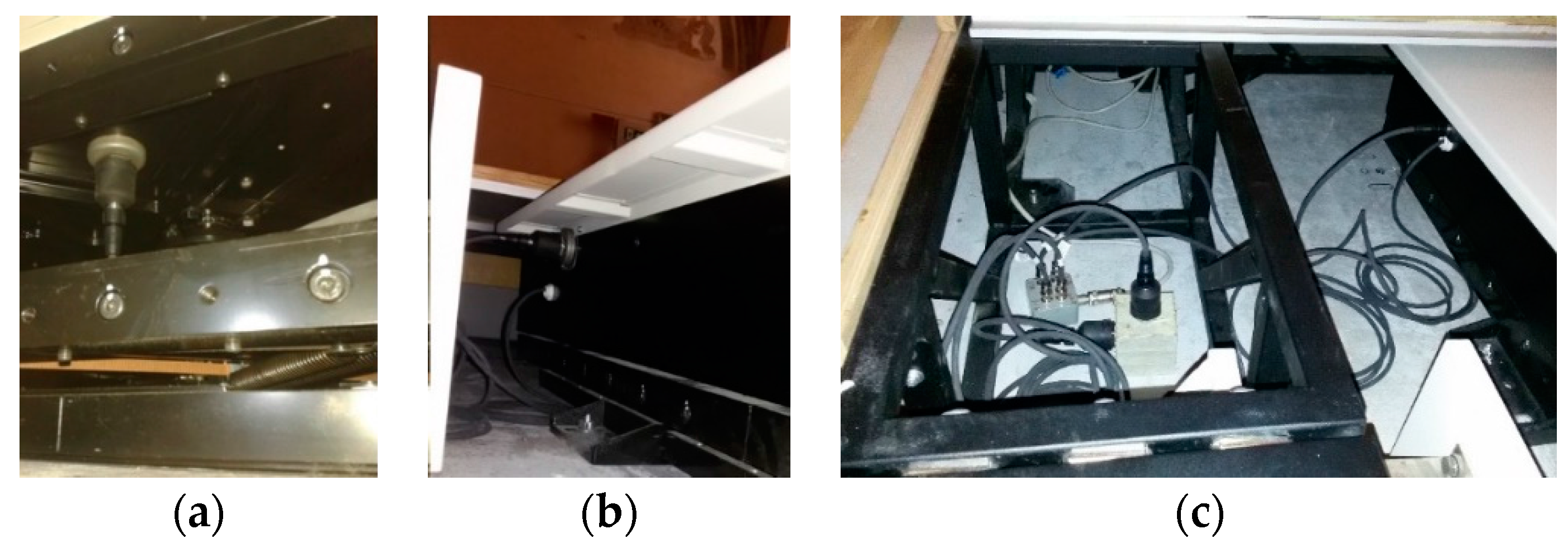
Figure 3.
Measured time response for a specific time length on the seismic base and the upper plate in: (a) horizontal direction; (b) vertical direction.
Figure 3.
Measured time response for a specific time length on the seismic base and the upper plate in: (a) horizontal direction; (b) vertical direction.
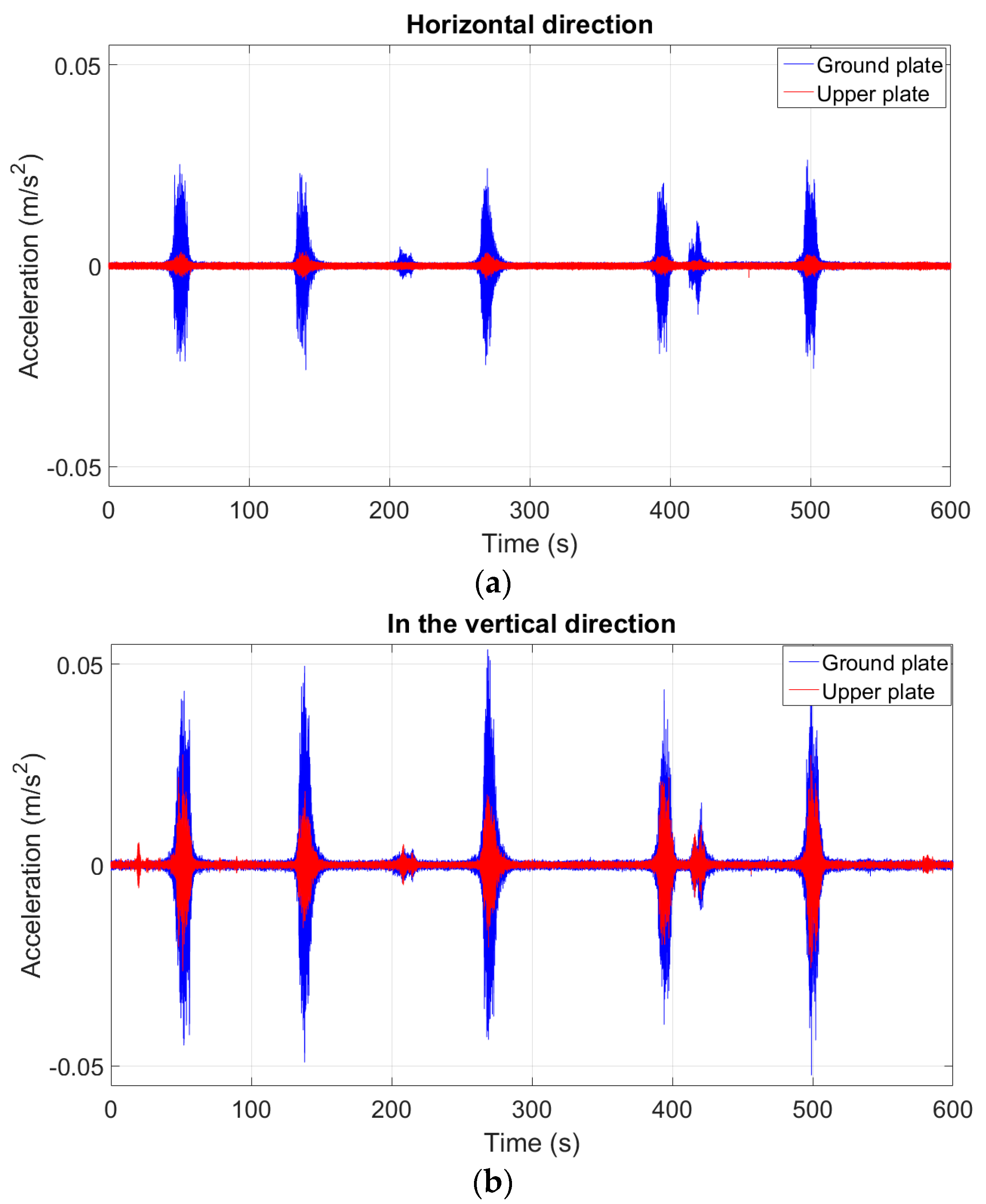
Figure 4.
Frequency response functions (FRFs) between the measured points on the seismic plate and the upper plate: in (a) horizontal direction; (b) vertical direction.
Figure 4.
Frequency response functions (FRFs) between the measured points on the seismic plate and the upper plate: in (a) horizontal direction; (b) vertical direction.
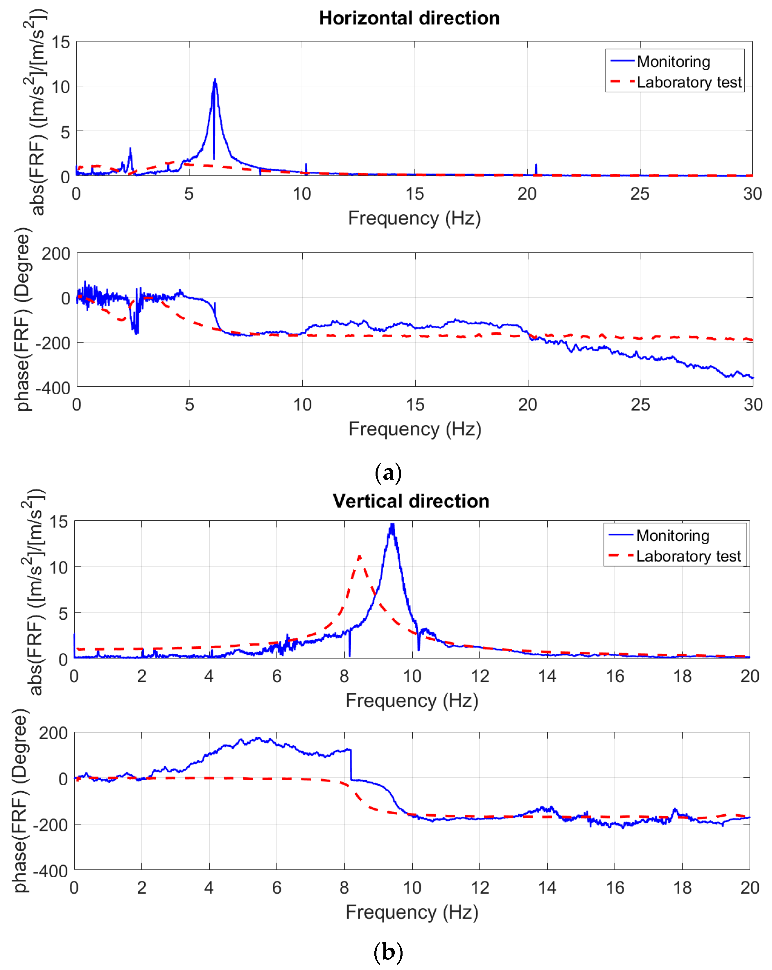
Figure 5.
The five degrees of freedom (5DOF) model of the isolator with nonlinear dissipating force and friction.
Figure 5.
The five degrees of freedom (5DOF) model of the isolator with nonlinear dissipating force and friction.

Figure 6.
FRF in the horizontal direction between the seismic plate and the upper plate obtained from the updated model (black line), and the corresponding FRF obtained from the monitoring (blue dotted line) and the older model (red dashed line).
Figure 6.
FRF in the horizontal direction between the seismic plate and the upper plate obtained from the updated model (black line), and the corresponding FRF obtained from the monitoring (blue dotted line) and the older model (red dashed line).

Figure 7.
FRF in the vertical direction between the seismic plate and the upper plate obtained from the updated model (black line), and the corresponding FRF obtained from the monitoring (blue dotted line) and the older model (red dashed line).
Figure 7.
FRF in the vertical direction between the seismic plate and the upper plate obtained from the updated model (black line), and the corresponding FRF obtained from the monitoring (blue dotted line) and the older model (red dashed line).
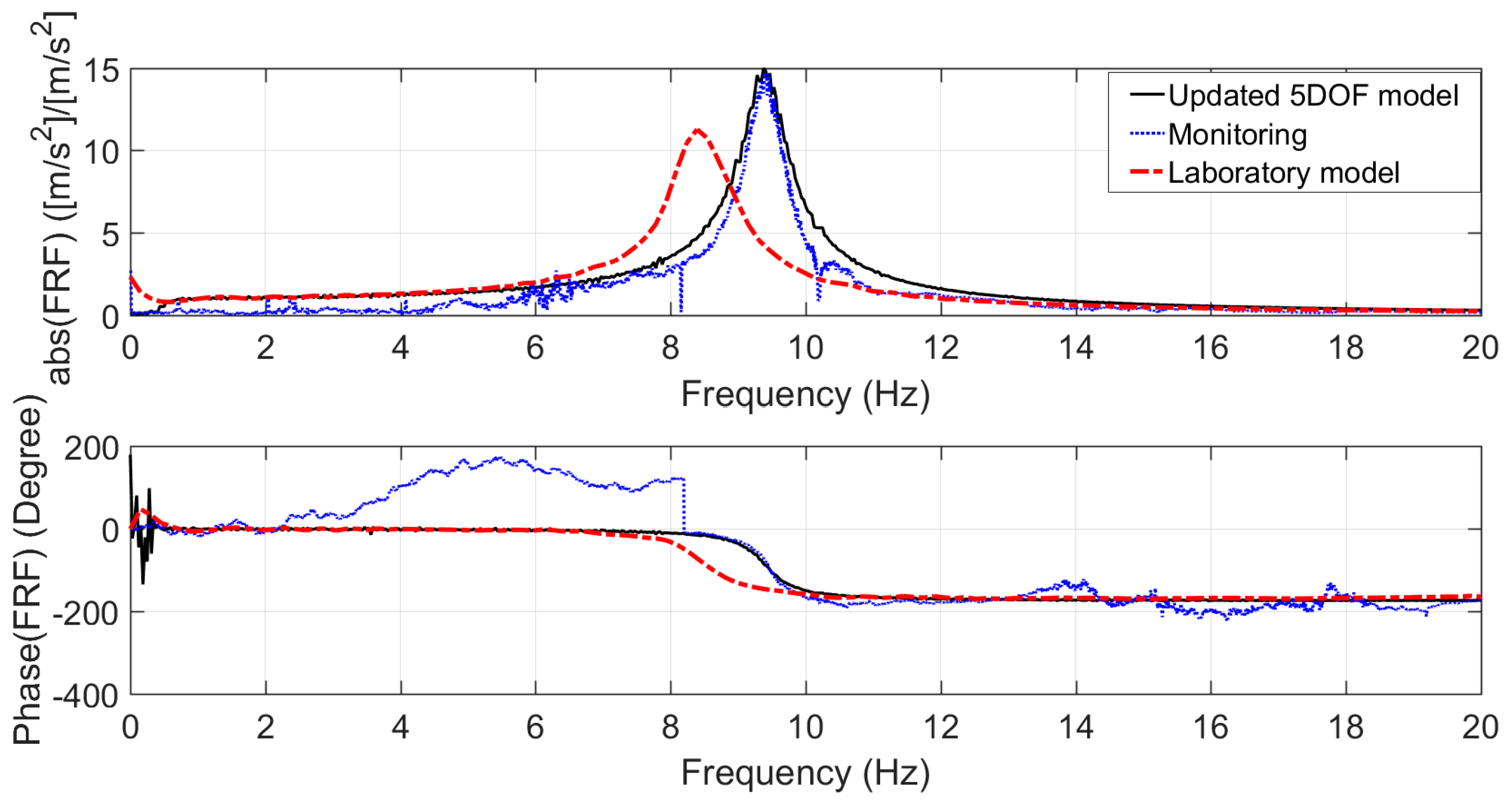
Figure 8.
FRF in horizontal direction: (a) between the seismic plate and the upper plate; and (b) between the seismic plate and the head of the statue.
Figure 8.
FRF in horizontal direction: (a) between the seismic plate and the upper plate; and (b) between the seismic plate and the head of the statue.
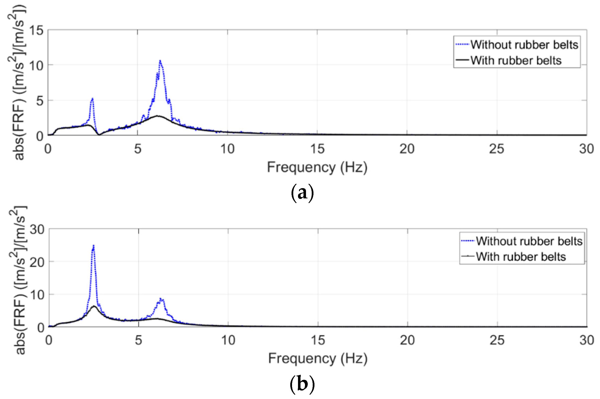
Figure 9.
FRF in the horizontal direction between the seismic plate and the upper plate obtained from the updated model with two different fiction coefficients: (blue dotted curve) and (black solid curve).
Figure 9.
FRF in the horizontal direction between the seismic plate and the upper plate obtained from the updated model with two different fiction coefficients: (blue dotted curve) and (black solid curve).
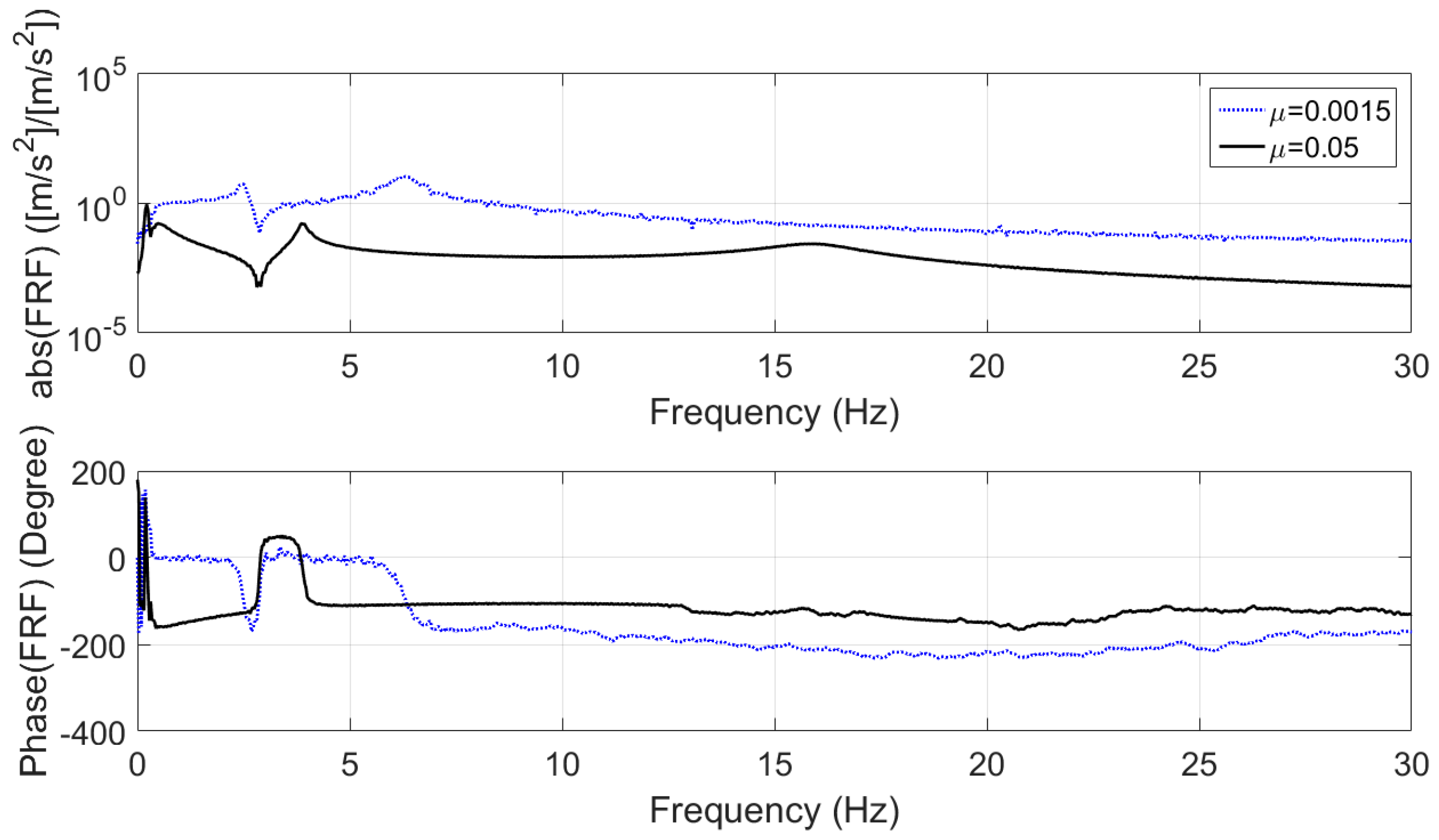
Figure 10.
A schematic of a ball-screw type inerter.
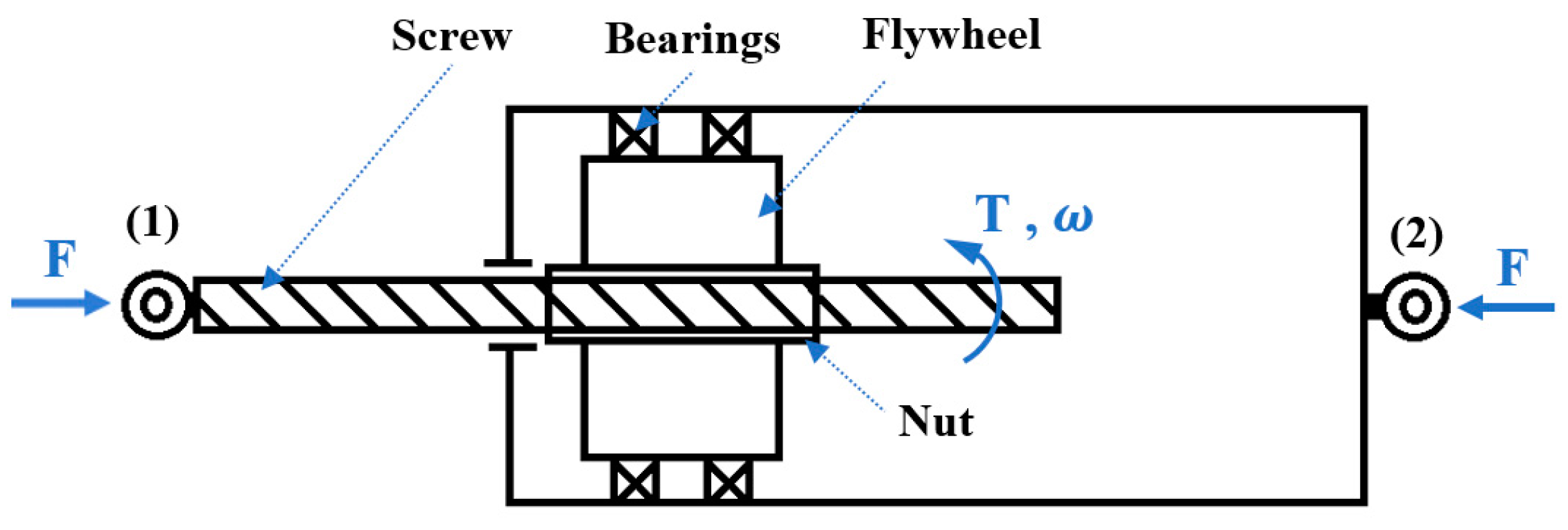
Figure 11.
7DOF model of the isolator system with two TMDs in the x direction combined with two inerters.
Figure 11.
7DOF model of the isolator system with two TMDs in the x direction combined with two inerters.

Figure 12.
FRFs obtained from the multi-degree-of-freedom (MDOF) model without and with TMDIs for case 1.
Figure 12.
FRFs obtained from the multi-degree-of-freedom (MDOF) model without and with TMDIs for case 1.
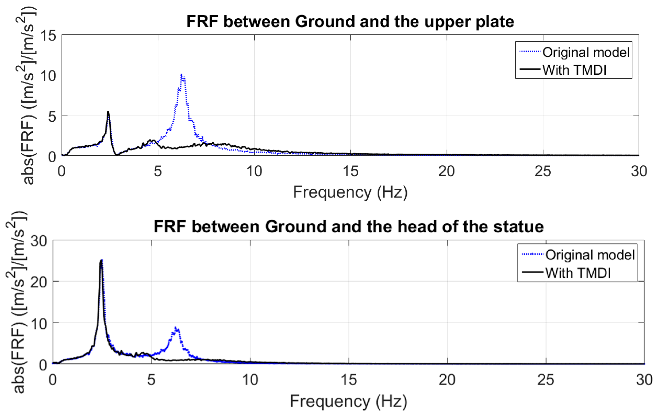
Figure 13.
FRFs obtained from the MDOF model without and with TMDIs for case 2.
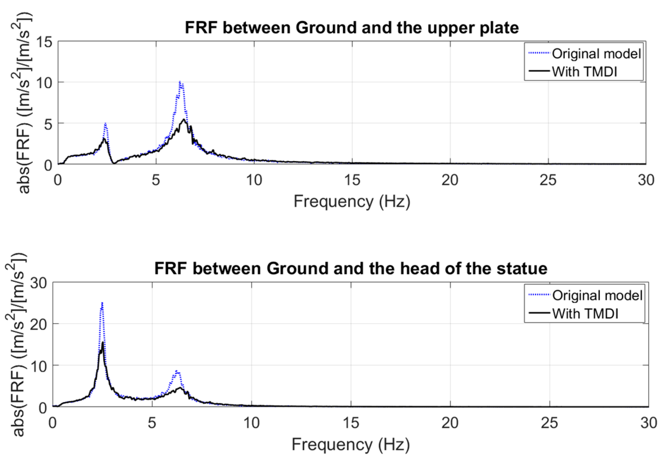
Figure 14.
FRFs obtained from the MDOF model without and with TMDIs for case 3.
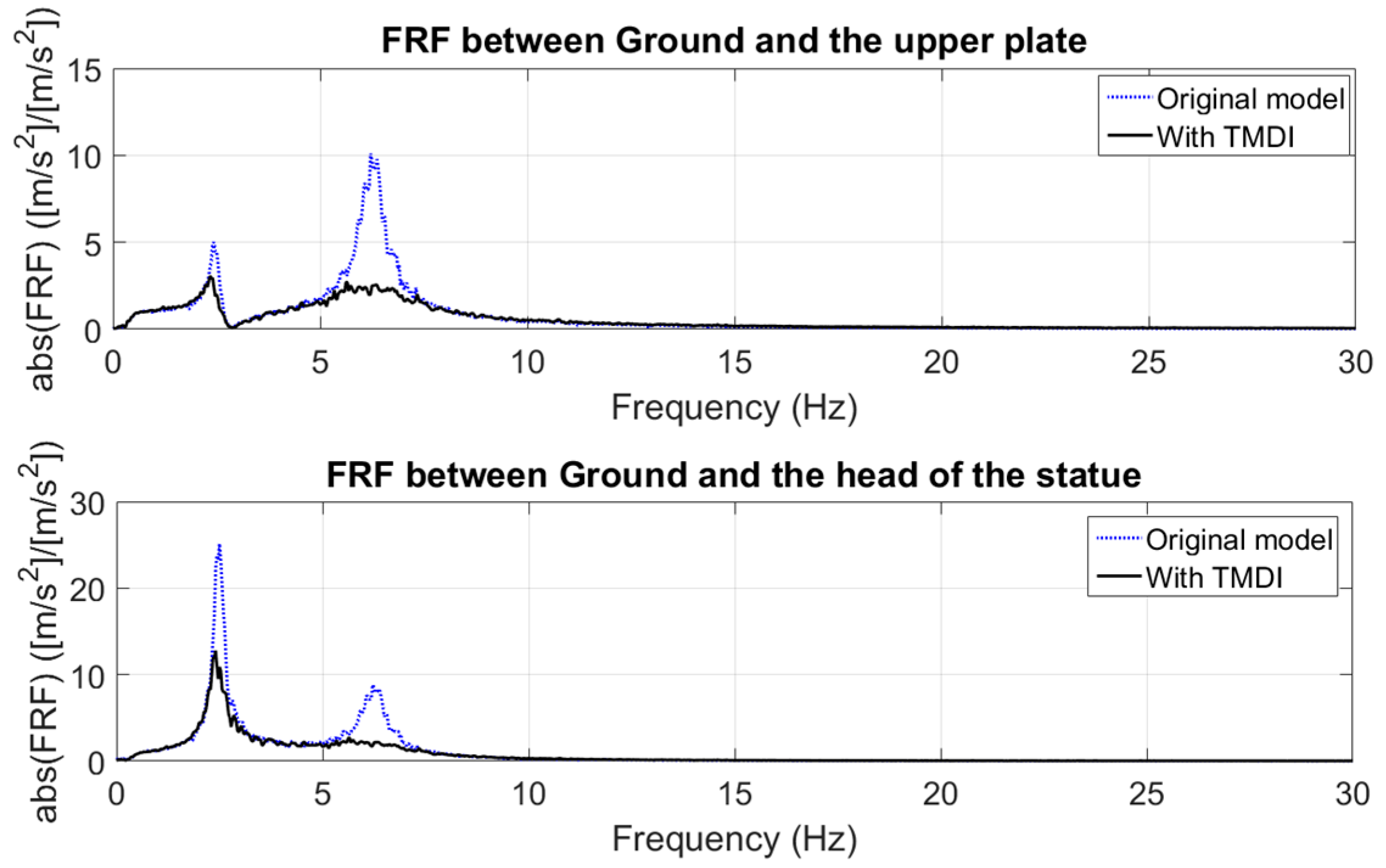
Figure 15.
Measured acceleration for North–South 1940 El Centro earthquake, used as excitation for the ground plate.
Figure 15.
Measured acceleration for North–South 1940 El Centro earthquake, used as excitation for the ground plate.

Figure 16.
FRFs obtained from the MDOF model without and with TMDIs for case 1 in Table 3; the excitation is the El Centro earthquake.
Figure 16.
FRFs obtained from the MDOF model without and with TMDIs for case 1 in Table 3; the excitation is the El Centro earthquake.

Figure 17.
FRFs obtained from MDOF model without and with TMDIs for case 2 in Table 3; the excitation is the El Centro earthquake.
Figure 17.
FRFs obtained from MDOF model without and with TMDIs for case 2 in Table 3; the excitation is the El Centro earthquake.
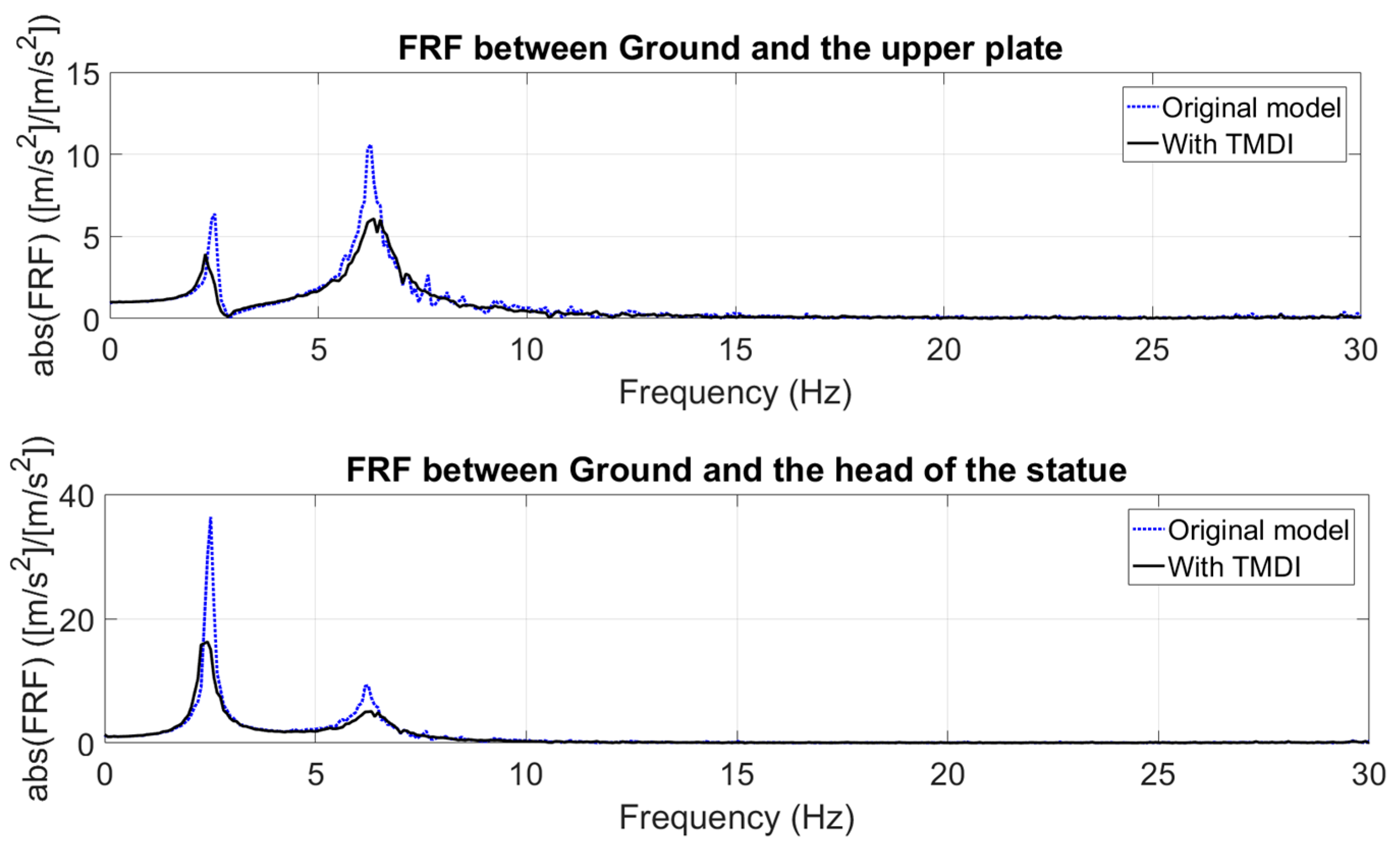
Figure 18.
Indices for the upper plate in the presence of uncertainties in the structural parameters: (a) ; and (b) .
Figure 18.
Indices for the upper plate in the presence of uncertainties in the structural parameters: (a) ; and (b) .
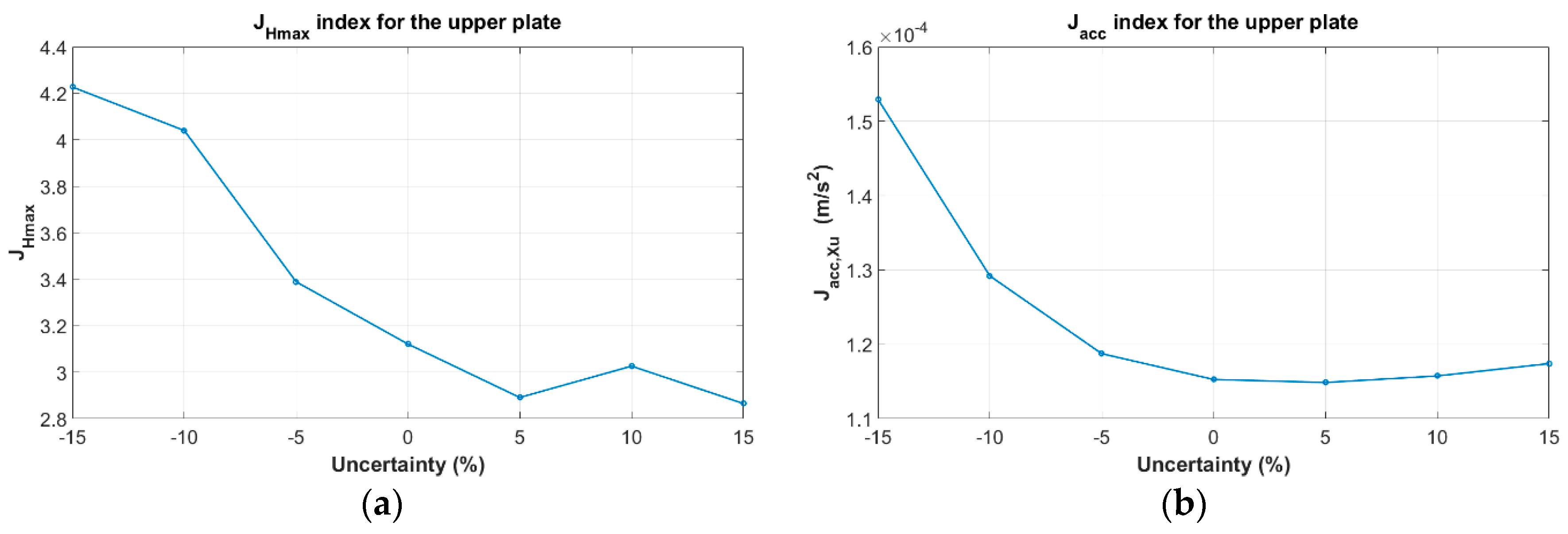
Figure 19.
Transfer function between the ground plate and the upper plate with TMDIs in the presence of various percentages of uncertainties in the damping and stiffness matrices of the structure ().
Figure 19.
Transfer function between the ground plate and the upper plate with TMDIs in the presence of various percentages of uncertainties in the damping and stiffness matrices of the structure ().

Table 1.
Specifications of sensor and acquisition system.
| Specification | Value | |
|---|---|---|
| 1 | Sampling frequency | 512 (Hz) |
| 2 | Number of samples for each file | 307,200 |
| 3 | Sensitivity of accelerometers | 1000 (mV/(m/s2)) |
| 4 | Frequency response (±5%) | 0.15 to 150 (Hz) |
| 5 | Overload limit (shock) | ±35 (g) |
| 6 | Working temperature range | −20 to +60 °C |
Table 2.
The updated parameters of the 5DOF model according to the FRF of the isolation system in the museum.
Table 2.
The updated parameters of the 5DOF model according to the FRF of the isolation system in the museum.
| Parameter | Before Monitoring | After Monitoring | Unit | |
|---|---|---|---|---|
| 1 | Mass of the statue | 740 | 740 | (kg) |
| 2 | Mass of the base | 1380 | 1380 | (kg) |
| 3 | Mass of the upper plate | 430 | 250 | (kg) |
| 4 | Vertical stiffness of rubber bearings () | 568 | 650 | (kN/m) |
| 5 | Horizontal stiffness of rubber bearings () | 109 | 109 | (kN/m) |
| 6 | Vertical damping of rubber bearings () | 950 | 650 | (Ns/m) |
| 7 | Horizontal damping of rubber bearings () | 100 | 100 | (Ns/m) |
| 8 | Static friction coefficient () | 0.020 | - | |
| 9 | Dynamic friction coefficient () | - | ||
| 10 | Constant coefficient of friction term () | 1 | 1 | - |
Table 3.
Chosen parameters for the TMDIs in different cases.
| Parameters | Case 1 | Case 2 | Case 3 |
|---|---|---|---|
| , | |||
| , | |||
| , | 0.2 | 0.4 | |
| , | |||
| , |
Table 4.
The result of the numerical solution of the isolation system; representation of the indices for different cases.
Table 4.
The result of the numerical solution of the isolation system; representation of the indices for different cases.
| Index | Uncontrolled (without TMDI) | Case 1: with TMDI; ,, | Case 2: with TMDI; ,, | Case 3: with TMDI; ,, |
|---|---|---|---|---|
| (for upper plate) |
Table 5.
The values of uncertainties assumed for stiffness and damping of the rubber bearings.
| Percent of Uncertainty (%) | Vertical Stiffness of Rubber Bearings (kN/m) | Horizontal Stiffness of Rubber Bearings (kN/m) | Vertical Damping of Rubber Bearings (Ns/m) | Horizontal Damping of Rubber Bearings (Ns/m) | |
|---|---|---|---|---|---|
| 1 | ±5 | 650 ± 32 | 109 ± 5 | 650 ± 32 | 100 ± 5 |
| 2 | ±10 | 650 ± 65 | 109 ± 11 | 650 ± 65 | 100 ± 10 |
| 3 | ±15 | 650 ± 97 | 109 ± 16 | 650 ± 97 | 100 ± 15 |
© 2017 by the authors. Licensee MDPI, Basel, Switzerland. This article is an open access article distributed under the terms and conditions of the Creative Commons Attribution (CC BY) license (http://creativecommons.org/licenses/by/4.0/).
Share and Cite
MDPI and ACS Style
Siami, A.; Cigada, A.; Karimi, H.R.; Zappa, E. Vibration Protection of a Famous Statue against Ambient and Earthquake Excitation Using A Tuned Inerter–Damper. Machines 2017, 5, 33. https://doi.org/10.3390/machines5040033
AMA Style
Siami A, Cigada A, Karimi HR, Zappa E. Vibration Protection of a Famous Statue against Ambient and Earthquake Excitation Using A Tuned Inerter–Damper. Machines. 2017; 5(4):33. https://doi.org/10.3390/machines5040033
Chicago/Turabian StyleSiami, Ali, Alfredo Cigada, Hamid Reza Karimi, and Emanuele Zappa. 2017. "Vibration Protection of a Famous Statue against Ambient and Earthquake Excitation Using A Tuned Inerter–Damper" Machines 5, no. 4: 33. https://doi.org/10.3390/machines5040033
Note that from the first issue of 2016, this journal uses article numbers instead of page numbers. See further details here.