Precision CNC Machining of Femoral Component of Knee Implant: A Case Study


Section of Manufacturing Technology, School of Mechanical Engineering, National Technical University of Athens, Heroon Politechniou 9, 15780 Athens, Greece
*
Author to whom correspondence should be addressed.
Machines 2018, 6(1), 10; https://doi.org/10.3390/machines6010010
Submission received: 13 February 2018
/
Revised: 27 February 2018
/
Accepted: 28 February 2018
/
Published: 2 March 2018
(This article belongs to the Special Issue Precision Machining)
Abstract
:The design and manufacturing of medical implants constitutes an active and highly important field of research, both from a medical and an engineering point of view. From an engineering aspect, the machining of implants is undoubtedly challenging due to the complex shape of the implants and the associated restrictive geometrical and dimensional requirements. Furthermore, it is crucial to ensure that the surface integrity of the implant is not severely affected, in order for the implant to be durable and wear resistant. In the present work, the methodology of designing and machining the femoral component of total knee replacement using a 3-axis Computer Numerical Control (CNC) machine is presented, and then, the results of the machining process, as well as the evaluation of implant surface quality are discussed in detail. At first, a preliminary design of the components of the knee implant is performed and the planning for the production of the femoral component is implemented in Computed Aided Manufacturing (CAM) software. Then, three femoral components are machined under different process conditions and the surface quality is evaluated in terms of surface roughness. Analysis of the results indicated the appropriate process conditions for each part of the implant surface and led to the determination of optimum machining strategy for the finishing stage.

1. Introduction
Partial or total replacement of a human knee with an implant can be achieved by a common surgical procedure, namely knee arthroplasty or knee replacement. Only in United States, over 500,000 knee replacement surgeries are reported each year [1], which are mostly for patients between 50 and 80 years old. One of the main reasons for the popularity of this type of surgery is the considerably high percentage of artificial knees still functioning even 20 years after the surgery. During this surgical operation, it is intended to replace damaged or worn components of the knee joint with artificially produced components or implants in order to facilitate proper knee motion of the patients and reduce disability problems and severe pain caused by joint diseases, usually osteoarthritis or rheumatoid arthritis. Apart from patients with advanced osteoarthritis, knee replacement may be suggested for younger patients with damage in the knee joint or bone or some type of deformity. Partial knee replacement is suggested in cases when damage is located only in a specific compartment of the knee. The specific purpose of this type of surgery is essentially to cap the end parts of the bones of the knee joint as well as the kneecap, by means of artificial components. More specifically, during knee replacement surgery, the main knee parts that are replaced are pertinent to the femoral and tibial surfaces near the knee joint as well as a part of the patella. For the components of the replacement implant, suitable metals or non-metallic materials are chosen and properly machined in order to resemble the natural shape of the knee as much as possible and allow for proper joint motion, resistance to wear and corrosion and biocompatibility. The machined components should adhere to highly restrictive regulations and exhibit considerable durability [2,3,4,5,6].
Knee replacement surgery and the design of implant components is currently considerably important and constitutes a part of ongoing research in the medical and engineering scientific communities. However, the first reported attempts to create and use artificial knee components in an actual knee replacement surgery date back to the end of the 19th century, when Gluck created the first artificial joint by ivory [7]. From that period, research is concentrated on the improvement of knee replacement components with a view to decrease considerably their failure rate and replicate proper joint motion as close as possible to the actual. In the 1950s, several new designs, such as the Waldius [8] and GUEPAR [9] knee implants were created; their basic characteristic was the bending-extending capabilities of the joint. During the next two decades, significant advances regarding the knee implant design were observed but still, artificial knee designs such as Geomedic [10] and Geometric [11] suffered from the inability to perform rotational motion and other types of knees such as Marmor [12] and Gunston [13] were exhibiting premature failure due to high contact stresses and material overloading. The ICLH (Imperial College-London Hospital) knee implant design, which was introduced by Freeman and Swanson in 1971 [14], exhibited a lower deformation and wear rate. Other designs presented during the 1970s include Total Condylar and Townley [15], which involved also the kneecap (patella) replacement and Oxford [16] and New Jersey LCS (Low Contact Stress) [17] knee designs, which used mobile bearings. In particular, the latter designs proved to possess capabilities, such as greater mobility and improved compatibility as they employed a secondary moving support surface.
Later, during the 1990s, designs employing moving bearings were also developed which were further enhanced by the use of newly developed materials and alloys and assistive guidelines from previous designs. A representative example of knee implant designs of this period is the B-P (Buechel-Pappas) Mark V which was created from Ti alloy with TiN coating or alternatively, from Co–Cr alloy in order to improve its wear resistance [18]. During this period, Walker et al. [19] introduced a new knee simulating machine with a view to test the kinematics of total knee implants, as well as the wear of these implants. Their machine was able to perform in a more realistic way than its predecessor models, which exhibited several disadvantages such as reduced accuracy in representing the forces exerted on various components of the knee implant or inadequate constraints. More recently, Harrysson et al. [20] proposed a new design method for knee implants, based on patient-specific Computed Tomography (CT) data which can provide among other, more accurate replication of the actual geometries of knee components and the reduced possibility of implant loosening. Lee et al. [21] also employed CT data in order to design the femoral component and afterwards, they created femoral components using rapid prototyping and Computer Numerical Control (CNC) machining methods. Finally, Song et al. [22] presented a thorough work related to the rapid manufacturing of femoral component using Selective Laser Melting (SLM) method which can provide a reliable way to produce customized implants. Results from all the aforementioned works can lead to useful guidelines regarding the design of knee implants. For example, it is crucial to avoid including redundant kinematic constraints for the knee implant components, to enable normal knee motion, to include moving bearings to the design, and to plan the rather copious machining process of the geometrically complex implant in an effective way.
In the present work, the methodology of designing and machining of the femoral component of total knee replacement using a 3-axis Computer Numerical Control (CNC) machining center is presented in several steps and is discussed in detail. After the machining processes take place, an evaluation of machined surface is performed by means of surface roughness measurements in order to determine the optimum process parameters for the machining of various parts of the implant. The present work is related to previous works by the members of the same scientific group, including studies on machining of femoral heads [23,24] and extends the preliminary work on the machining of knee implant, as reported in [25].
2. Design of the Implant Geometry and Machining Processes
2.1. Design of the Knee Implant Components
Despite the fact that the main focus of the present work is set on the design and machining process of the femoral component, it is considered to be crucial to study the design of the whole knee implant at the initial stage in order to determine the appropriate dimensions of this part in relation to the total knee assembly and then study the femoral component separately. The design of the knee implant components was conducted by means of SolidworksTM software in which both the design and manufacturing of the knee implant is able to be studied. As with every engineering design, design constraints should be properly defined in order for the implant to comply with the desired shape of implant parts and allow for normal motion of the implant components so as to provide a satisfying replacement of the damaged knee.
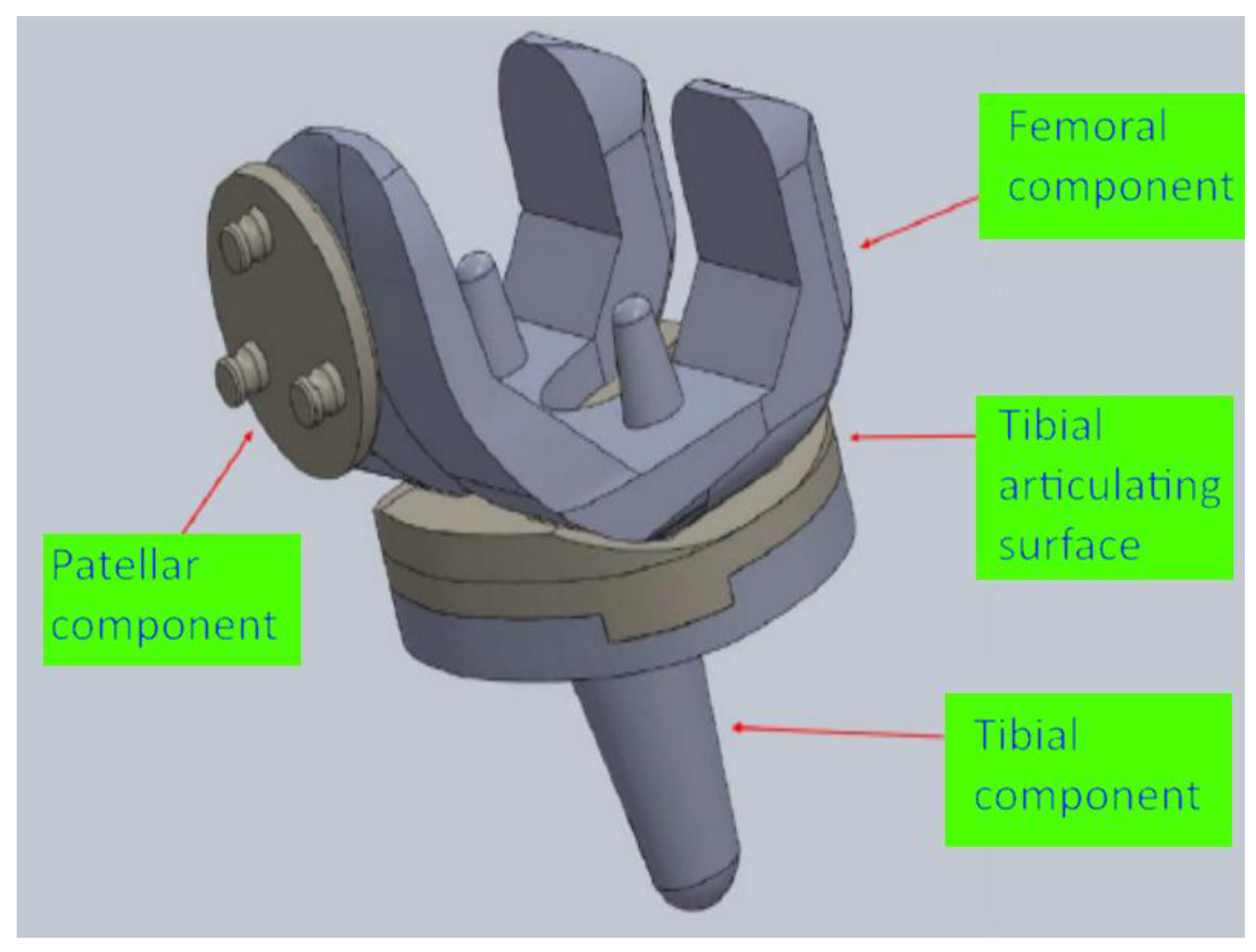
The design of the knee implant parts complies with the international standard ISO 7207-1 [26], in which the geometry of both total and partial knee implant components is defined in detail. More specifically, for the present work, it is assumed that the total knee implant, which is designed, corresponds to the left knee of a male human with constrained rotational movement. In Figure 1, a schematic of the bones near the knee joint is presented, along with a schematic indicating the position of the implant after the surgery. The knee implant components, which will be designed as an assembly, include the femoral component, the tibial component, the tibial articulating surface, and the patellar component, as can be seen in Figure 2.
The design of the femoral component contains two different steps, namely the design of its outer and inner surface. This approach is required due to the considerably different geometries of the outer and inner surfaces. More specifically, the outer surface is essentially a sculptured surface that is composed of various curved areas, as this shape is necessary for the contact between the femoral component and the tibial and patellar components of the implant and facilitates normal knee motion. In the outer surface, a groove is also formed, resembling the trochlear groove of the actual human femur bone. As for the design of the inner surface, it is required that it should be strongly fixed on the bone; it is usually achieved by the use of acrylic cement between the implant and the bone during the surgery. The fixation of this surface to the bone is further enhanced by two conical stems on the inner surface, intended to be inserted into two holes in the bone. Although the design of the inner surface is generally simpler, there is an important restriction regarding the thickness of the inner surfaces, as they should have the least possible thickness in order to reduce the need of material removal from the bone during the insertion of the implant.
The design of the tibial component includes the design of two different structural elements, a stem and a platform. The stem is intended to aid to the fixation of the tibial component to the tibia and the platform is essential for the connection of the tibial component to the tibial articulating surface. For the stem, it is required that its thickness is large enough to withstand the relatively high forces will be exerted on it whereas the dimensions of the platform, namely its width and depth should closely match the actual dimensions of the upper part of human tibia. As for the design of the tibial articulating surface it is subjected to two main requirements, namely to withstand the loading from the femur and implement the fixation on the tibial component. In order to fulfill these requirements, the size of the contact surface with the tibial components is designed sufficiently large so as to protect the joint from receiving excessive loading and enable normal knee motion.
Finally, the design of the patellar component aims at the facilitation of the movement of the patella on the trochlear groove of the femur. Thus, a dome-like shape for the lower surface of the patellar component is adopted in order to be able to assist to the sliding movement of this component in the trochlear groove. As for the upper surface of the patellar component, its geometrical shape is properly adjusted so that it provides strong fixation on the patella bone.
2.2. Design of the Machining Process of the Femoral Component
After the components of the total knee implant were carefully designed according to the international standards and relevant requirements, the focus is set on the machining process of the femoral component of the knee implant. The design of the machining process of this component, which includes complex geometrical shapes, is essential to be conducted on a specialized Computer Aided Manufacturing (CAM) software, such as SolidCAM, which can be accessed through SolidWorks software.
Machining of complex, “sculptured” surfaces is important in various industries such as automotive, aerospace and optical components industry, as well as bioengineering. One of the main challenges concerning the machining of such surfaces is the reduction of machining time, as it is considerably difficult to achieve the required dimensional accuracy and surface quality. Apart from the use of cutting tools with special geometry, the machining strategy needs to be carefully planned in order to achieve the desired geometrical features and suitable process parameters are required to be determined as well. Thus, all of these tasks need to be appropriately addressed by the use of CAM software in order to perform the machining process of the femoral component.
CAM software are specialized to assist in various stages of product manufacturing. Most commonly, they involve the use of an integrated Computer Aided Design (CAD) editor or, such as the case of SolidCAM software, are themselves integrated in the framework of a CAD software and their purpose is eventually to produce the code (G-Code) in order to control CNC machine tools for manufacturing the desired parts. Using this type of software, details about the machining process such as the definition of appropriate cutting tools for the machining process and their characteristics, the desired operations on the workpiece, such as hole drilling, contour, etc., process parameters during the various stages of the process and machining strategies can be input at first. Then, G-code can be generated, in respect to the type of CNC machine used, given that an appropriate post-processor exists. Furthermore, a simulation of the intended machining operations can be performed in order to verify that the machining will be performed safely and according to the desired goals or detect possible mistakes and perform the necessary adjustments.
The basic challenge which exists in the present work is that, due to the fact that the outer and inner surface of the femoral component contain sculptured surfaces, mounting of the workpiece on the machining center bed is difficult to be performed. For that reason, it is considered more appropriate to perform the machining process in two separate phases; during the first phase, it is intended to create the internal surface of the femoral component and during the second phase, the workpiece will be reverted, and then, machining of the outer surface will occur. Thus, in the CAM software, different coordinate systems will be defined for the two stages as well as different Stock and Target materials.
2.2.1. First Phase of Machining
During the first phase of machining, the emphasis is set on the creation of the inner surfaces. This phase constitutes the main material removal phase and the cutting tools will remove material up to a specific height until the second phase will take place. For the first phase, four cutting tools, both flat and ball end, will be employed, as can be also seen in Table 1. It is important to note that, in the early stages of the machining process, tools with flat end and a larger diameter are preferred in order to remove large bulk of material quickly (roughing stage) without requirements for high accuracy of produced shape. However, at the final stages of the machining process, cutting tools with smaller diameter and ball end are selected in order to render appropriately the final sculptured surface according to the desired dimensional and geometrical requirements (finishing stage). The initial dimensions of the cylindrical workpiece are: 50 mm diameter and 39.3 mm height. The workpiece material, which was chosen is stainless steel 316L, which is appropriate for the femoral component [27,28].
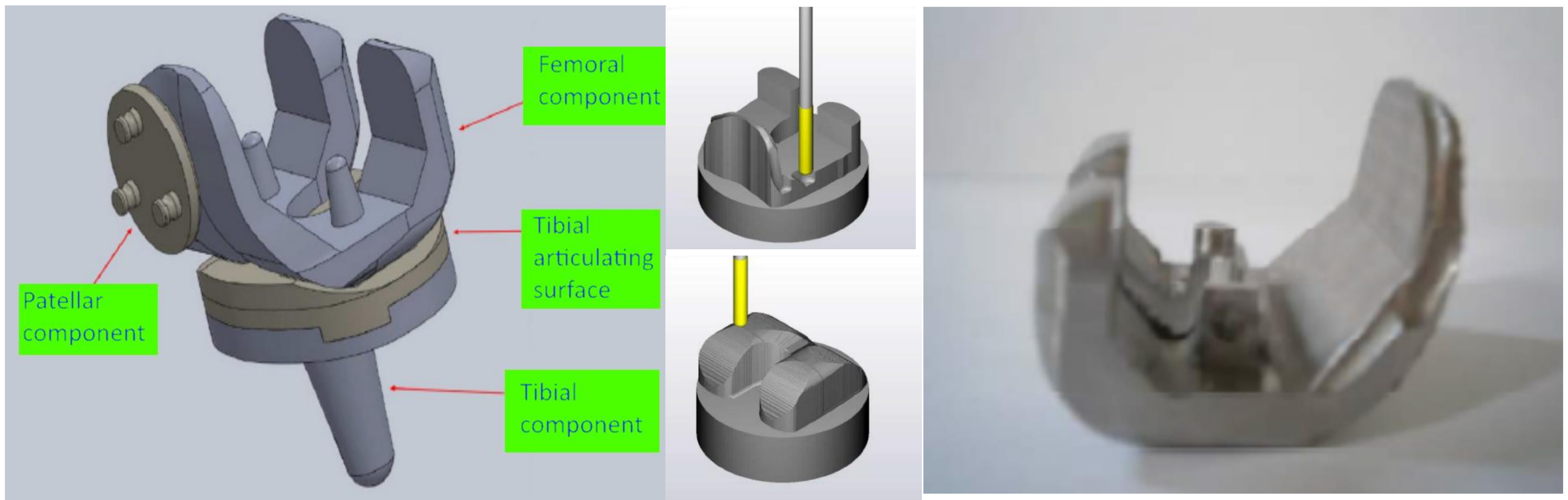
In order to achieve the creation of the desired shape of the inner surface of the femoral component, the 16 mm diameter cutting tool was first employed in order to reduce the initial height of the workpiece at several passes, as can be seen in Figure 3a. Afterwards, a cavity was formed in the region where the inner surfaces of the implant will later be created. Using the same cutting tool, a contour cutting process was also performed in order to create the front and back sculptured surfaces. The next stage, as depicted in Figure 3b, involved the use of 6 mm flat end cutting tool in order to continue the contour cutting process with the rendering of more features of the implant surface, and then, the 6 mm ball end tool was employed to create the final shape of the front sculptured surface. Finally, the finishing stage was implemented by using the 4 mm diameter cutting tool both for the front and the back sculptured surfaces, as can be seen in Figure 3c.
2.2.2. Second Phase of Machining
The second phase of machining is related to the machining of the outer surface of the femoral component. For this phase of machining, three cutting tools are selected, both the flat and ball end. Initially, as can be seen in Figure 4a,b, a 16 mm flat end cutting tool is used to perform contour cutting at a fixed height at each pass, and then, a 6 mm flat end cutting tool performed cutting with fixed y coordinate at each pass (roughing phase). In the end, the finishing process was implemented using a 4 mm ball end cutting tool using the same strategy as with the 6 mm diameter cutting tool, as can be seen in Figure 4c.
2.3. Initial Machining Test
After the definition of machining operations and production of G-code in the CAM software and after the simulation of the machining processes was successfully finished, it was decided that a test run, replicating the machining process in the actual CNC machining, was necessary before the final machining process in order to ensure that the generated G-code was producing an accurate and reliable outcome and verify the simulation results. Furthermore, it is important to test the behavior of the cutting tools during the machining process in order to choose the appropriate process parameters that lead to avoidance of chattering, as it is impossible to be determined from the simulation in the CAM software. The test run was performed on a cylindrical bulk of polymer material, and was concluded successfully, indicating that the actual machining process can be performed without problems.
3. Machining of the Implant and Measurement of Surface Roughness
3.1. Machining Process of the Implant
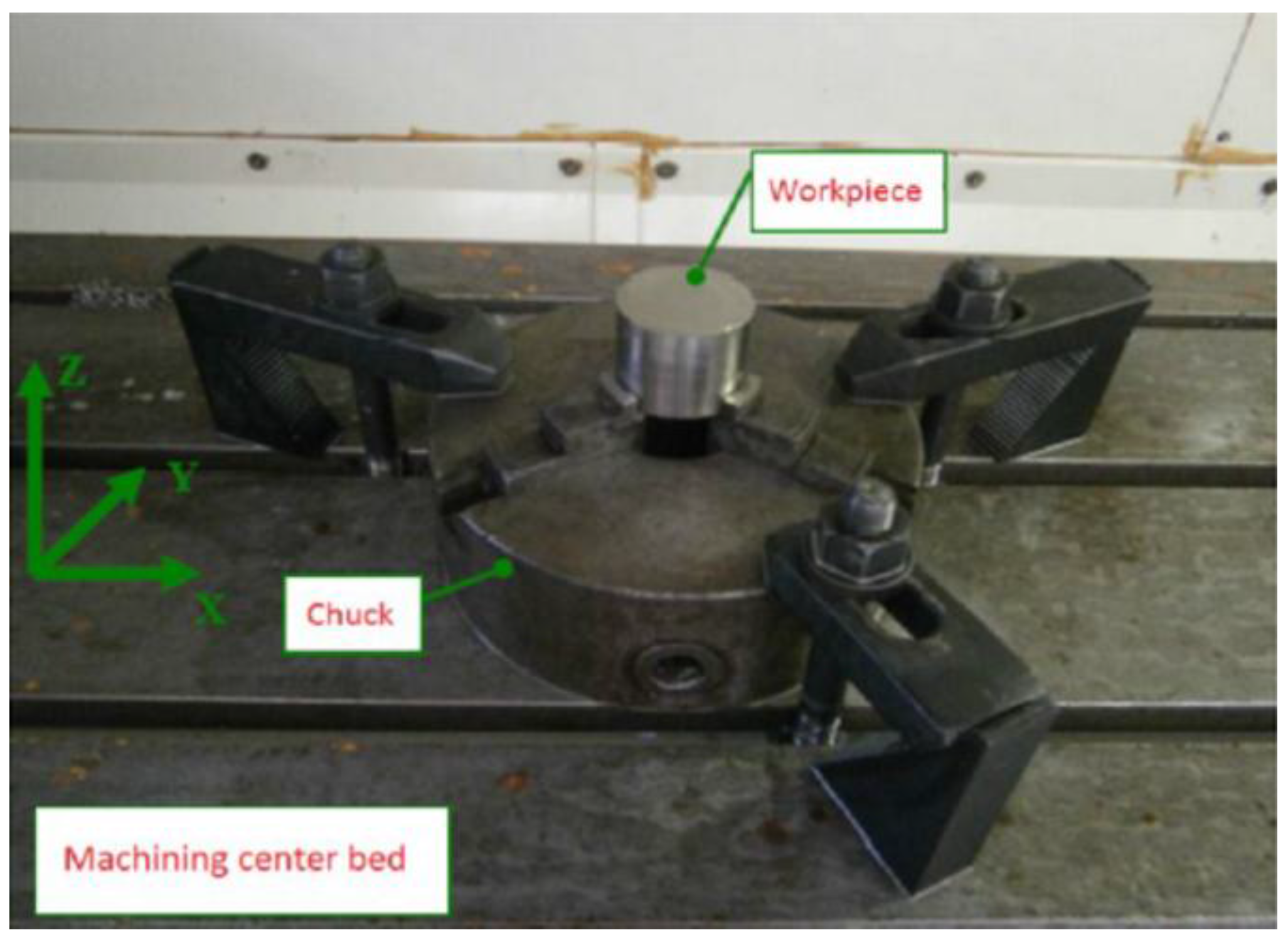
After the various stages of the machining process were designed in the CAM software and successfully verified by the test run, the setup of the 3-axis CNC machining center was performed. As the initial bulk is a cylindrical workpiece, it was fixed on the machine with a chuck, as depicted in Figure 5.
After the cutting tools were selected and the necessary setup was performed on the CNC machine, the first phase of the machining process took place. The first phase was expected to last for a relatively long time, as it is required to select small depths of cut and low cutting speed when machining stainless steel workpieces. After the machining process was completed, the inner surface of the implant was created, as can be seen in Figure 6. It is worth noting that the existence of several markings on the produced surfaces was observed, created by the contact of the upper part of the cutting tool with these surfaces when material removal was performed on the lower parts of the inner surface of the implant.
During the second phase of the machining process the workpiece is mounted on the machine tool bed after it is reverted, by using a specially designed platform, as can be seen in Figure 7. The use of this platform is required as it is impossible to fix otherwise the workpiece appropriately on the machine tool. In order to ensure the stability of fixation of the implant, it is required that the internal surfaces of the workpiece are properly aligned on the platform surfaces, parallel to the machining center bed. After the implant is mounted on the platform and fixation is properly performed by two screws, the platform is clamped on a chuck.
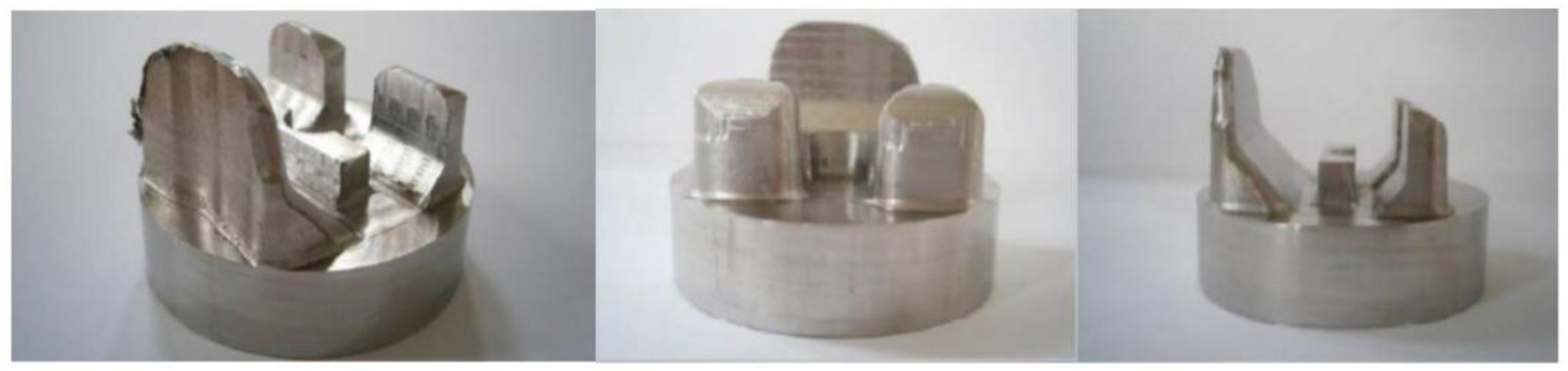
When the aforementioned procedure for the machining of the outer surface of the implant is completed, as can be seen in Figure 8. This process was repeated two times with different process parameters at various zones of the implant during finishing stage, in order to investigate the effect of process parameters on surface quality. The process parameters that were employed for the machining of all three implant during the finishing stage are presented in Table 2.
3.2. Surface Quality Evaluation
After the machining process of the femoral component is completed, it is considered important to evaluate the quality of the produced surfaces, as it is directly connected to the tribological behavior and wear resistance of the implant. Inappropriate machining conditions, leading to excessive surface roughness, can prevent not only the adequate performance and reliability of the implant but also its life cycle [29]. Furthermore sufficient surface quality after machining of the implant reduces the need for further processes, such as polishing. For that reason, surface roughness measurements were conducted on the three different implants with a view to determine the optimum process parameters for the finishing stage of the implant machining process. Due to the fact that the implant contains sculptured surfaces, the measurement of the surface roughness with a profilometer is a demanding process and special care has to be paid for the positioning of the measuring device and also for correct sampling length (Ln) and cut-off length (Lc) values. In the present work, a Surtronic 3+ Taylor Hobson profilometer was employed and a sampling length (Ln) of 2.4 mm was selected, as well as a cut-off length (Lc) of 0.8 mm. As per the manufacturer manual, the used profilometer has a resolution of 0.01 μm and accuracy of parameters is given as 2% of reading plus least significant digit in μm. Surface roughness was performed in each of the five zones presented in Figure 9, both in the left and the right side (or inner and outer side) of the upper surface of the implant (the region of the lateral and medial condyles, respectively) and the measurements are repeated three times. In the following analysis the lateral and medial condyles are referred to as inner and outer sides, respectively.
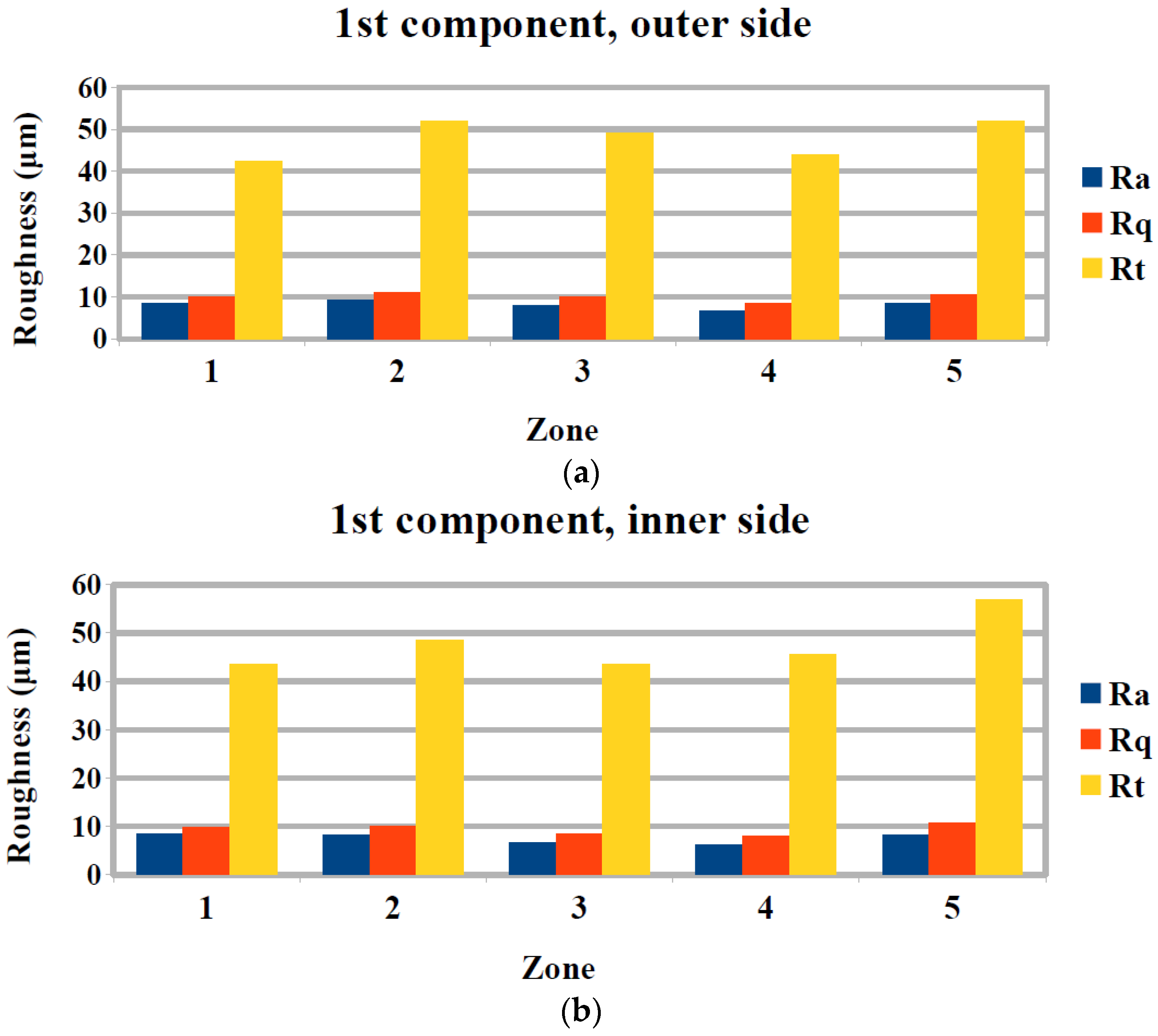
The evaluation of surface roughness was performed by Ra, Rq, Rt, which represent the arithmetic average surface roughness, root mean squared roughness, and maximum height of the profile, respectively. Especially, Ra is the most popular indicator of surface roughness in industrial practice until today. As for the first femoral component, which was machined with the same conditions in every zone, it can be seen from Figure 10a,b, that there are some differences in the Ra values in the different zones.
These differences can be directly attributed to the different geometry of each zone, as zones 1, 2, and 5 are more curved, whereas region 3 and 4 are almost flat. Thus, it is observed that the finishing process is more effective in the flat regions with values of Ra of about 6–7 μm, whereas Ra exceeds 8 μm in the other regions. Similar trends can be observed in the case of Rq and Rt measurement with the exception of zone 1, which has a relatively low value of Rt when compared to the other zones.
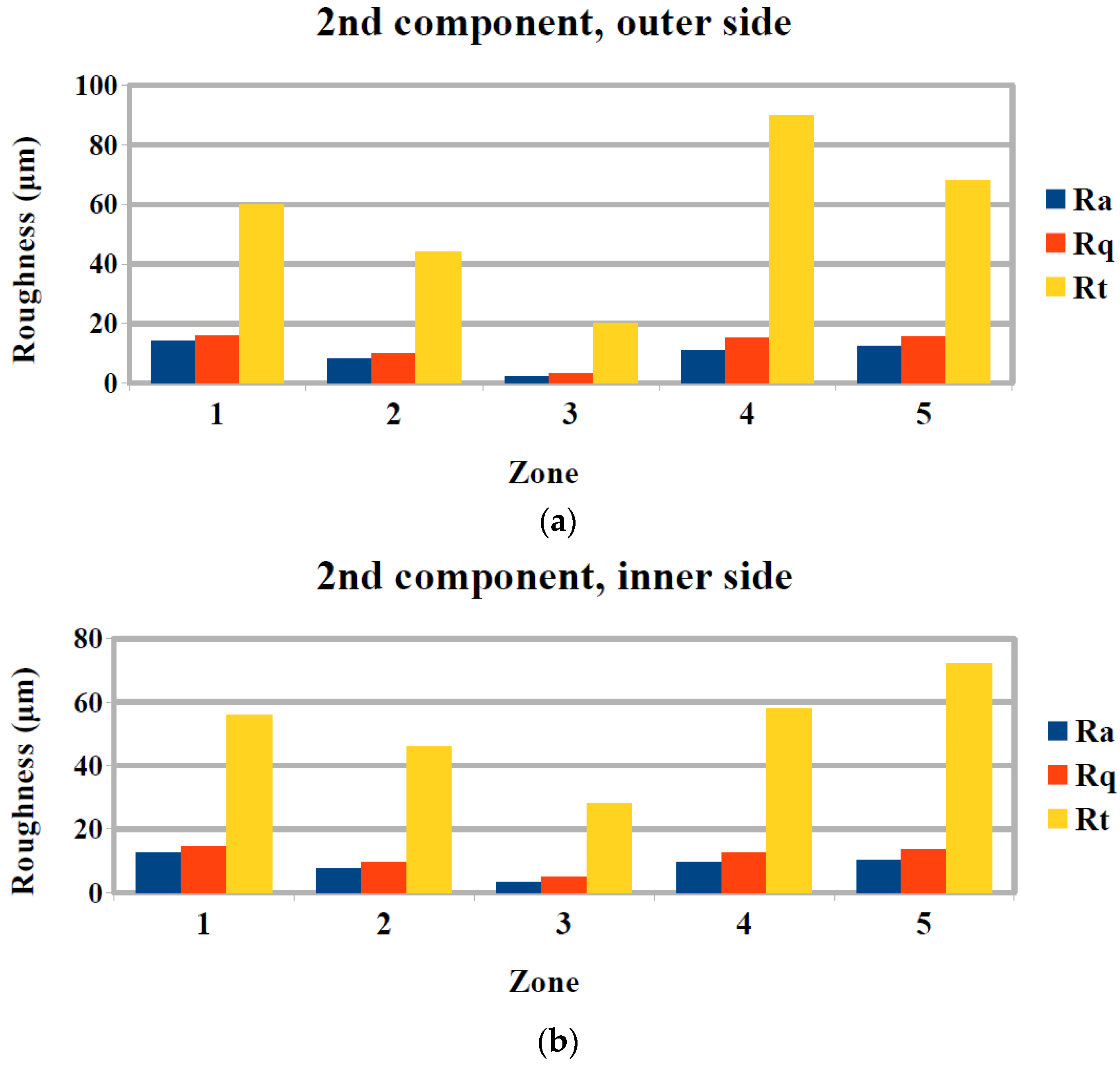
A comparison of surface roughness measurements between the different components, machined with different conditions, can reveal the effect of process parameters to the surface quality of each zone of the femoral component. For zone 1, comparison between results depicted in Figure 10, Figure 11 and Figure 12 show that, a reduction of feed rate resulted in an increase of Ra and subsequent reduction of both feed rate and spindle speed resulted in a further small increase of Ra. For zone 2, the change of process parameters resulted in almost unchanged values of Ra. For zone 3, a decrease of feed rate resulted in a considerable decrease of average surface roughness, whereas a decrease of spindle speed resulted in an increase of Ra. For zone 4, a decrease of spindle speed resulted in an increase of Ra, whereas a further increase of spindle speed with a slight decrease of feed rate led to a slight decrease of Ra. Finally, for zone 5, it was observed that the reduction of both feed rate and spindle speed resulted initially in higher Ra and a subsequent reduction of both the parameters resulted in slightly lower Ra.
As usually, the effect of feed rate on Ra is that a decrease of feed rate leads to a decrease of Ra and also an increase of spindle speed is beneficial to the surface quality, the results for some of the five zones seem somewhat unexpected. However, these discrepancies can be attributed to the different curvature of each zone; results consistent with the aforementioned behavior are exhibited in zones which are fairly flat, such as zones 3 and 4, but in zones that are more curved different trends exist. The same trends are observed in the case of Rq and Rt measurements on the three femoral components.
The difference between measurements in the inner and the outer side of the upper surface of the femoral component was also investigated during the analysis of surface roughness of the implants. Regarding Ra values, it was found that, with the exception of one zone for the 2nd and 3rd component and two zones for the 1st, the general trend of variations of Ra in respect to different geometry and process parameters was similar. Furthermore, it was observed Ra values were larger in the vast majority of measurements in the outer side rather than the inner side.
Finally, the previous analysis allowed for the determination of optimum process parameters, namely feed rate and spindle speed for the finishing stage. Within the examined range of process parameters values the optimum values for each zone regarding Ra, were observed in the first component for zones 1, 4, 5, and for the second component for zones 2 and 3. Similar conclusions were drawn when examining the values of Rq and Rt.
4. Conclusions
In the present work, various stages of manufacturing the femoral component of knee prosthesis are presented, including the design of geometry and machining operations, as well as the actual machining process and the subsequent determination of surface quality.
The specific requirements for the design of the femoral component in respect to the total knee replacement assembly were determined, and particular situations that require special attention during machining were identified. These particularities were properly taken into consideration during the design of the required machining operations using SolidCAM software.
Furthermore, after machining three different femoral components with variable process parameters values during the finishing stage several important conclusions were drawn. Especially, surface roughness was shown to vary considerably with changes in the surface curvature and the effect of process parameters to the surface quality was also shown to be dependent of the curvature of the surface. Finally, the optimum parameters, namely feed rate and spindle speed, for the reduction of surface roughness for various zones of the femoral implant were determined.
Author Contributions
Nikolaos I. Galanis and Dimitrios E. Manolakos conceived and designed the experiments; Nikolaos I. Galanis performed the experiments; Nikolaos I. Galanis and Nikolaos E. Karkalos analyzed the data; Angelos P. Markopoulos contributed materials and analysis tools; Nikolaos E. Karkalos and Angelos P. Markopoulos wrote the paper.
Conflicts of Interest
The authors declare no conflict of interest.
References
- Carr, B.C.; Goswami, T. Knee implants—Review of models and biomechanics. Mater. Des. 2009, 30, 398–413. [Google Scholar] [CrossRef]
- Magdziak, M. The influence of a number of points on results of measurements of a turbine blade. Aircr. Eng. Aerosp. Technol. 2017, 89, 953–959. [Google Scholar] [CrossRef]
- Felhő, C.; Kundrák, J. Comparison of theoretical and real surface roughness in face milling with octagonal and circular inserts. Key Eng. Mater. 2014, 581, 360–365. [Google Scholar] [CrossRef]
- Kundrák, J.; Varga, G. Possibility of Reducing Environmental Load in Hard Machining. Key Eng. Mater. 2012, 496, 205–210. [Google Scholar] [CrossRef]
- Kundrák, J.; Varga, G.; Deszpoth, I.; Molnar, V. Some Aspects of the Hard Machining of Bore Holes. Appl. Mech. Mater. 2013, 309, 126–132. [Google Scholar] [CrossRef]
- Illés, B.; Tamás, P.; Dobos, P.; Skapinyecz, R. New challenges for quality assurance of manufacturing processes in industry 4.0. Solid State Phenom. 2017, 261, 481–486. [Google Scholar] [CrossRef]
- Brand, R.A.; Mont, M.A.; Manring, M.M. Biographical sketch: Themistocles Gluck (1853-1942). Clin. Orthop. Relat. Res. 2011, 469, 1525–1527. [Google Scholar] [CrossRef] [PubMed]
- Wilson, F.C.; Fajgenbaum, D.M.; Venters, G.C. Results of knee replacement with the Walldius and geometric prostheses. A comparative study. J. Bone Jt. Surg. Am. 1980, 62, 497–503. [Google Scholar] [CrossRef]
- Aubriot, J.-H.; Deburge, A.; Genet, J.-P. GUEPAR hinge knee prosthesis. Orthop. Traumatol. Surg. Res. 2014, 100, 27–32. [Google Scholar] [CrossRef] [PubMed]
- Van Loon, C.J.; Hu, H.P.; Van Horn, J.R.; De Waal Malefijt, M.C. The Geomedic knee prosthesis. A long-term follow-up study. Acta Orthop. Belg. 1993, 59, 40–44. [Google Scholar] [PubMed]
- Coventry, M.B.; Finerman, G.A.; Riley, L.H.; Turner, R.H.; Upshaw, J.E. A new geometric knee for total knee arthroplasty. Clin. Orthop. Relat. Res. 1972, 83, 157–162. [Google Scholar] [CrossRef] [PubMed]
- Kolstad, K.; Wigren, A. Marmor Knee Arthroplasty: Clinical Results and Complications during an Observation Period of at least 3 Years. Acta Orthop. Scand. 1982, 53, 651–661. [Google Scholar] [CrossRef] [PubMed]
- Lavernia, C.; C Alcerro, J.; Contreras Raygoza, J. Knee arthroplasty: Growing trends and future problems. Int. J. Clin. Rheumatol. 2010, 5, 565–579. [Google Scholar] [CrossRef]
- Goldberg, V.M.; Henderson, B.T. The Freeman-Swanson ICLH total knee arthroplasty. Complications and problems. JBJS 1980, 62, 1338–1344. [Google Scholar] [CrossRef]
- Mallory, T.H.; Smalley, D.; Danyi, J. Townley Anatomic Total Knee Arthroplasty Using Total Tibial Component with Cruciate Release. Clin. Orthop. Relat. Res. 1982, 169, 197–201. [Google Scholar] [CrossRef]
- Goodfellow, J.W.; Tibrewal, S.B.; Sherman, K.P.; O’Connor, J.J. Unicompartmental Oxford Meniscal knee arthroplasty. J. Arthroplast. 1987, 2, 1–9. [Google Scholar] [CrossRef]
- Buechel, F.F.S.; Buechel, F.F.J.; Pappas, M.J.; Dalessio, J. Twenty-year evaluation of the New Jersey LCS Rotating Platform Knee Replacement. J. Knee Surg. 2002, 15, 84–89. [Google Scholar] [PubMed]
- Buechel, F.F.; Pappas, M.J. Principles of Human Joint Replacement: Design and Clinical Application; Springer International Publishing: Berlin/Heidelberg, Germany, 2015. [Google Scholar]
- Walker, P.S.; Blunn, G.W.; Broome, D.R.; Perry, J.; Watkins, A.; Sathasivam, S.; Dewar, M.E.; Paul, J.P. A knee simulating machine for performance evaluation of total knee replacements. J. Biomech. 1997, 30, 83–89. [Google Scholar] [CrossRef]
- Harrysson, O.L.A.; Hosni, Y.A.; Nayfeh, J.F. Custom-designed orthopedic implants evaluated using finite element analysis of patient-specific computed tomography data: Femoral-component case study. BMC Musculoskelet. Disord. 2007, 8, 91. [Google Scholar] [CrossRef] [PubMed]
- Lee, J.; Chen, H.; Luo, C.-W.; Chang, K.-Y. Rapid Prototyping and Multi-axis NC Machining for The Femoral Component of Knee Prosthesis. Life Sci. J. 2010, 6, 73–77. [Google Scholar]
- Song, C.; Yang, Y.; Wang, Y.; Wang, D.; Yu, J. Research on rapid manufacturing of CoCrMo alloy femoral component based on selective laser melting. Int. J. Adv. Manuf. Technol. 2014, 75, 445–453. [Google Scholar] [CrossRef]
- Galanis, N.I.; Manolakos, D.E. Surface roughness prediction in turning of femoral head. Int. J. Adv. Manuf. Technol. 2010, 51, 79–86. [Google Scholar] [CrossRef]
- Galanis, N.; Manolakos, D. Surface roughness of manufactured femoral heads with high speed turning. Int J. Manuf. Mater. Mech. Eng. 2009, 5, 371–382. [Google Scholar] [CrossRef]
- Markopoulos, A.P.; Karkalos, N.E.; Galanis, N.I.; Manolakos, D.E. Design and Machining of the Femoral Component of Total Knee Implant. Solid State Phenom. 2017, 261, 313–320. [Google Scholar] [CrossRef]
- Denkena, B.; Köhler, J.; Turger, A.; Helmecke, P.; Correa, T.; Hurschler, C. Manufacturing conditioned wear of all-ceramic knee prostheses. Procedia CIRP 2013, 5, 179–184. [Google Scholar] [CrossRef]
- Otani, T.; Whiteside, L.A.; White, S.E.; McCarthy, D.S. Effects of femoral component material properties on cementless fixation in total hip arthroplasty. A comparison study between carbon composite, titanium alloy, and stainless steel. J. Arthroplast. 1993, 8, 67–74. [Google Scholar] [CrossRef]
- Gervais, B.; Vadean, A.; Raison, M.; Brochu, M. Failure analysis of a 316L stainless steel femoral orthopedic implant. Case Stud. Eng. Fail. Anal. 2016, 5, 30–38. [Google Scholar] [CrossRef]
- Affatato, S.; Ruggiero, A.; Grillini, L.; Falcioni, S. On the roughness measurement of the knee femoral components. In Proceedings of the 10th International Conference BIOMODLORE 2013, Vilnius, Lithuania, 20–22 September 2013; Vilnius Gediminas Technical University Press Technica: Vilnius, Lithuania, 2013; pp. 16–18. [Google Scholar] [CrossRef]
Figure 1.
Bones around the knee joint and position of knee replacement after the knee arthroplasty.
Figure 2.
Parts of the designed knee replacement assembly.

Figure 3.
Snapshots from the simulation of the first machining stage: (a) Machining of the front surface of the femoral component using 16 mm diameter tool; (b) Machining of the back surface of the femoral component using 6 mm diameter tool; and, (c) Machining of inner surfaces of the femoral component using 4 mm ball end tool.
Figure 4.
Snapshots from the simulation of the second machining stage: (a) Roughing stage of the second machining phase using 16 mm diameter tool; (b) Machining of sculptured surface of the femoral component using 6 mm ball end tool; and, (c) Finishing stage of the second machining phase, using 4 mm diameter ball end tool.
Figure 5.
Clamping of workpiece on the machining center bed.

Figure 6.
Views of the workpiece after the first machining stage.

Figure 7.
The platform for mounting the workpiece on the machining center bed for the second machining stage.
Figure 7.
The platform for mounting the workpiece on the machining center bed for the second machining stage.
Figure 8.
Views of the implant after the second machining stage.
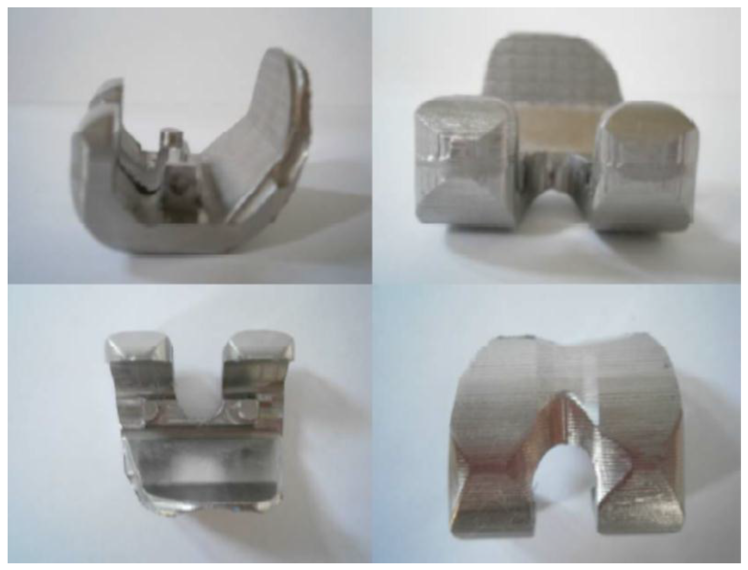
Figure 9.
Zones of surface roughness measurement.
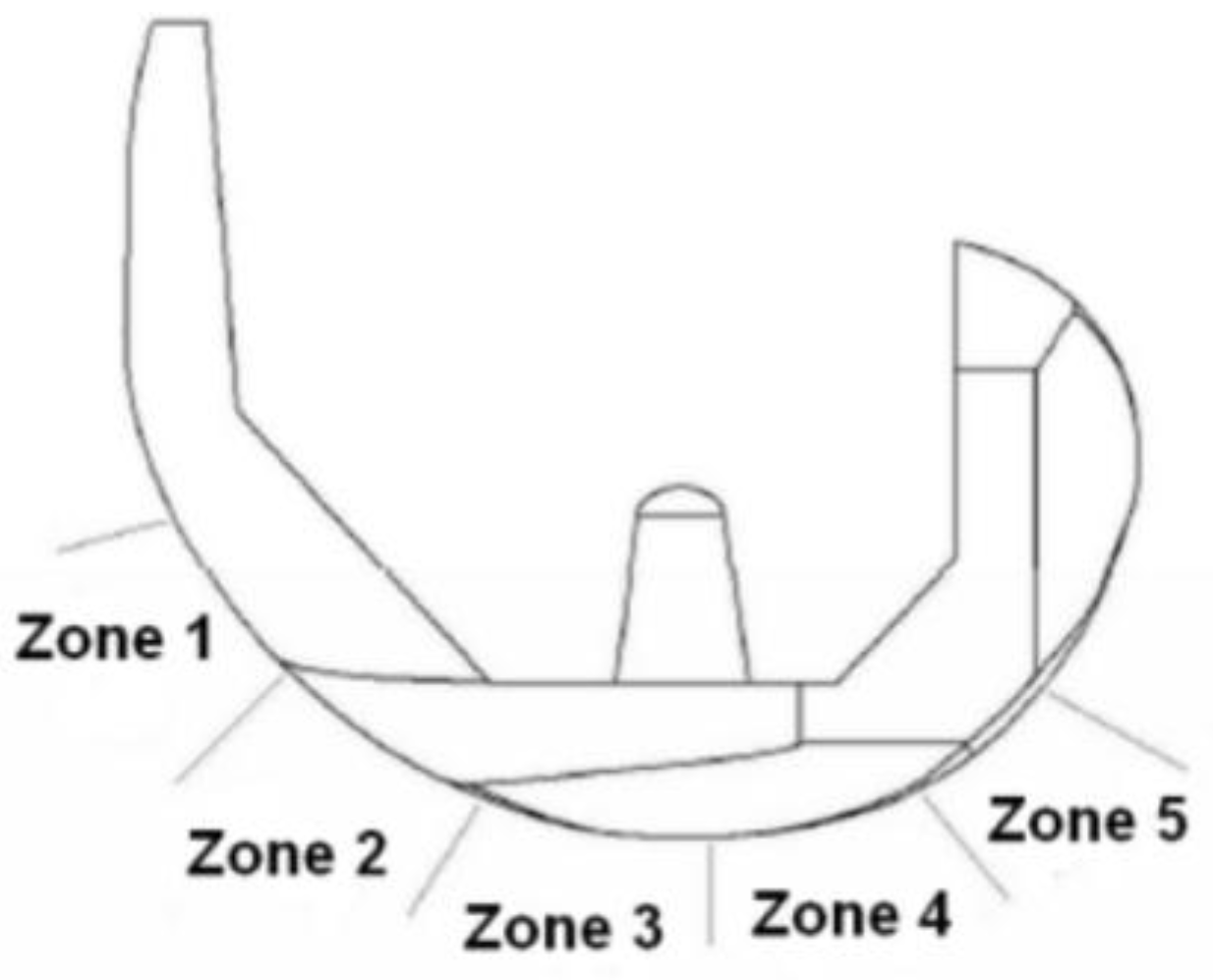
Figure 10.
Surface roughness measurement results for the first femoral component for (a) outer and (b) inner side.
Figure 10.
Surface roughness measurement results for the first femoral component for (a) outer and (b) inner side.

Figure 11.
Surface roughness measurement results for the second femoral component for (a) outer and (b) inner side.
Figure 11.
Surface roughness measurement results for the second femoral component for (a) outer and (b) inner side.

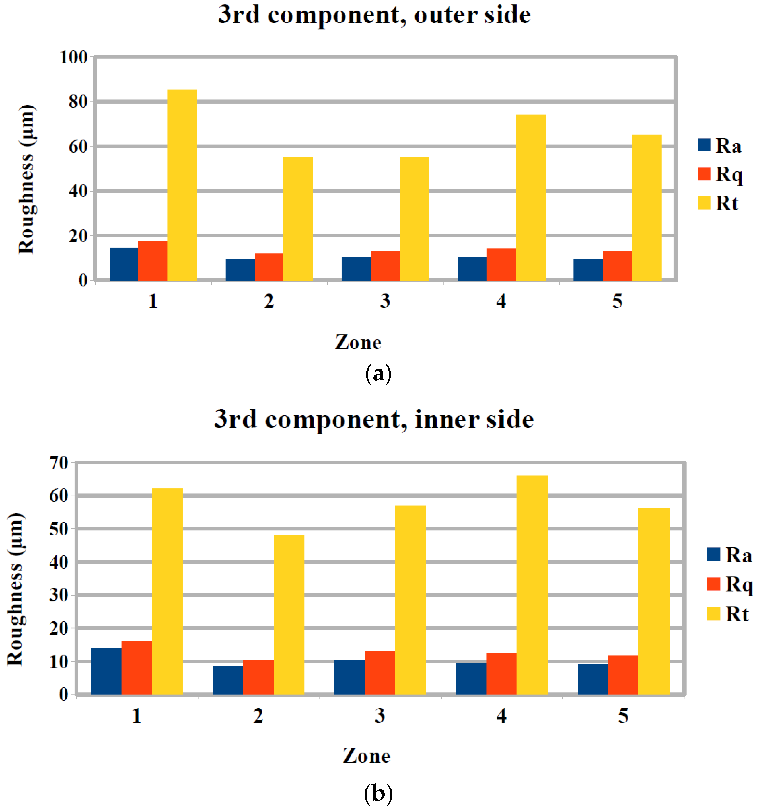
Figure 12.
Surface roughness measurement results for the third femoral component for (a) outer and (b) inner side.
Figure 12.
Surface roughness measurement results for the third femoral component for (a) outer and (b) inner side.

Table 1.
Characteristics of the cutting tools employed in the present work.
| No | Type | Diameter (mm) | Material |
|---|---|---|---|
| 1 | Flat end | 16 | carbide |
| 2 | Flat end | 6 | cobalt alloy |
| 3 | Ball end | 6 | cobalt alloy |
| 4 | Ball end | 4 | carbide |
Table 2.
Machining parameters values for each zone and each component.
| Zones of the Component | ||||||
|---|---|---|---|---|---|---|
| Component | 1 | 2 | 3 | 4 | 5 | |
| 1st | Feed rate (mm/min) | 100 | 100 | 100 | 100 | 100 |
| Spindle speed (rpm) | 2500 | 2500 | 2500 | 2500 | 2500 | |
| 2nd | Feed rate (mm/min) | 90 | 70 | 50 | 100 | 90 |
| Spindle speed (rpm) | 2500 | 2500 | 2500 | 2250 | 2250 | |
| 3rd | Feed rate (mm/min) | 70 | 50 | 100 | 90 | 70 |
| Spindle speed (rpm) | 2250 | 2250 | 2000 | 2000 | 2000 | |
© 2018 by the authors. Licensee MDPI, Basel, Switzerland. This article is an open access article distributed under the terms and conditions of the Creative Commons Attribution (CC BY) license (http://creativecommons.org/licenses/by/4.0/).
Share and Cite
MDPI and ACS Style
Markopoulos, A.P.; Galanis, N.I.; Karkalos, N.E.; Manolakos, D.E. Precision CNC Machining of Femoral Component of Knee Implant: A Case Study. Machines 2018, 6, 10. https://doi.org/10.3390/machines6010010
AMA Style
Markopoulos AP, Galanis NI, Karkalos NE, Manolakos DE. Precision CNC Machining of Femoral Component of Knee Implant: A Case Study. Machines. 2018; 6(1):10. https://doi.org/10.3390/machines6010010
Chicago/Turabian StyleMarkopoulos, Angelos P., Nikolaos I. Galanis, Nikolaos E. Karkalos, and Dimitrios E. Manolakos. 2018. "Precision CNC Machining of Femoral Component of Knee Implant: A Case Study" Machines 6, no. 1: 10. https://doi.org/10.3390/machines6010010
Note that from the first issue of 2016, this journal uses article numbers instead of page numbers. See further details here.