Characteristics Analysis and Comparison of High-Speed 4/2 and Hybrid 4/4 Poles Switched Reluctance Motor

Department of Mechatronics Engineering, Kyungsung University, Busan 48434, Korea
*
Author to whom correspondence should be addressed.
Machines 2018, 6(1), 4; https://doi.org/10.3390/machines6010004
Submission received: 1 January 2018
/
Revised: 23 January 2018
/
Accepted: 25 January 2018
/
Published: 26 January 2018
(This article belongs to the Special Issue High Speed Motors and Drives: Design, Challenges and Applications)
Abstract
:This paper presents a characteristics analysis and performance comparison of high-speed two-phase 4/2 and hybrid single-phase 4/4 switched reluctance motors (SRMs). Although the motors are advantageous as high-speed drives, both conventional structures have high torque ripple as a result of the presence of the torque dead zone. In this paper, solutions to the torque dead zone problem for each motor are discussed. For the 4/2 SRM, a wide-rotor stepper-type is adopted, while for the 4/4 SRM, the structure is changed to a hybrid by adding permanent magnets (PMs). Both motors have a non-uniform air gap to modify their inductance profile, which leads to the elimination of the torque dead zone. A finite-element method was used to analyze the characteristics of each motor. Then, the manufactured motors were tested through experiments, and lastly, their performance was compared.
1. Introduction
Nowadays, high-speed machines are utilized in a wide range of applications, and the interest in developing high-speed motor drives is growing. Switched reluctance motors (SRMs) have some advantages as high-speed drives because of their simple structure: they have no windings or permanent magnets (PMs) on the rotor, which contributes to a low rotor inertia and a relatively easy cooling compared to other motor types. However, they suffer from high torque ripple, vibration, and acoustic noise, which dominate as the main research topics for SRMs.
The pole and phase number of SRMs play an important role in determining their performance. These affect the switching frequency, which impacts the viability of the motor for high-speed applications. There are some known pole number and phase combinations, such as three-phase 6/4, three-phase 12/8, and four-phase 8/6 SRMs. The selection of phase numbers is determined by the self-start capability, rotating direction, reliability, cost, power density, and efficiency [1]. A higher phase number means more power density and reliability, as a failure in one phase can still be compensated for by other remaining phases. However, the phase number may correspond to the converter size and an increased number of phase switches, which is not preferable in high-speed applications. Meanwhile, the selection of the SRM stator and rotor poles also has an impact on the switching frequency. Lower stator and rotor pole numbers are more effective in reducing core loss in the high-speed region [2]. The relationship can be described by the formula below:
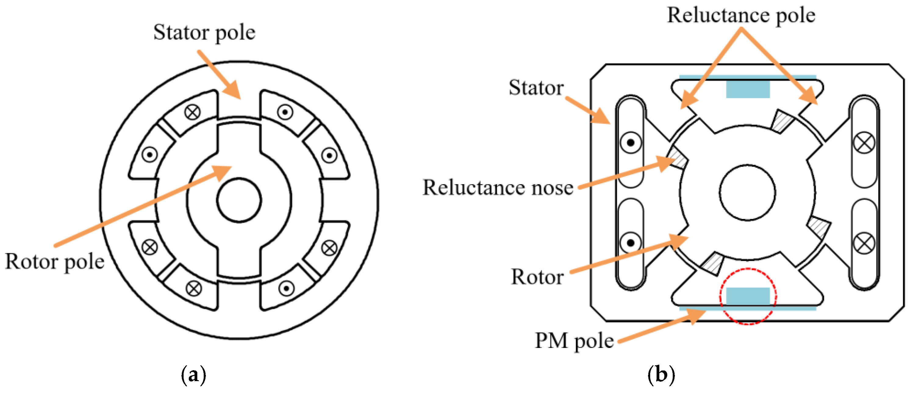
where is the stator frequency, is the rotating speed, and is the number of rotor poles. On the basis of the considerations above, a single-phase 4/4 SRM and a two-phase 4/2 SRM have been selected in this study as high-speed motor drives. However, the single-phase machine lacks the ability to self-start; thus it needs additional PMs usually located on the stator, which is called the hybrid structure. According to the positioning of the PMs, single-phase hybrid SRMs can be categorized into -, -, and Cyrano-types, as discussed in [3]. The Cyrano-type hybrid SRM structure has four stator reluctance poles and two PM poles [4,5,6]. In this study, the Cyrano-type is used as the base for the proposed single-phase hybrid SRM. However, unlike the true Cyrano-type, which uses an asymmetric rotor that has a “nose”, the conventional structure considered here eliminates the nose for an easier manufacturing process. Figure 1 shows the structure for conventional 4/2 and Cyrano-type hybrid 4/4 SRMs.
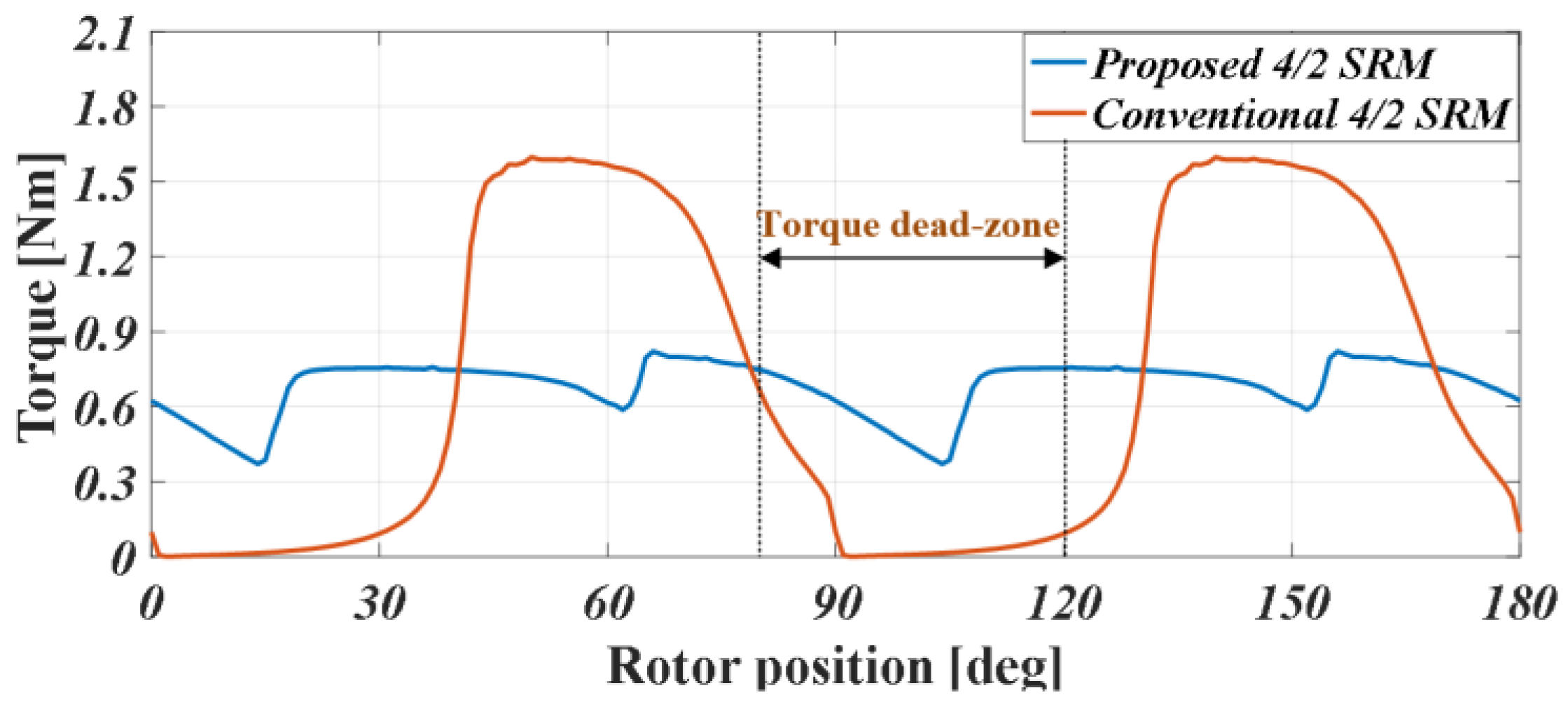
The reluctance pole in Figure 1b acts as the usual stator pole in conventional SRMs. Both conventional 4/2 and hybrid 4/4 SRMs have a simple power circuit. However, they have a high torque ripple and torque dead zone, where the rotor produces no torque at all, as shown in Figure 2. Single-and two-phase SRMs have this inherent torque dead region because of an absence of the torque over-lap region between phases [7]. If the motor is activated while the rotor is in the torque dead zone, then the motor cannot self-start, which is particularly the case in a conventional single-phase SRM.
In this paper, a solution to the torque ripple and torque dead zone for 4/2 and 4/4 SRMs is presented to enable their practical application. First, the concept of the non-uniform air gap, which is used to modify the inductance characteristics and widen the positive torque region for the proposed high-speed motors, is introduced. Then their static characteristics, such as inductance and torque, have been compared through simulations using finite-element analysis (FEA) in FEMM and Ansoft Maxwell software. Lastly, the no-load and load performances have been compared through experiments.
2. Concept of Proposed 4/2 and 4/4 SRMs
2.1. Proposed 4/2 SRM
The inductance in SRMs depends on the air-gap length and overlap area of the rotor and stator poles [8]. Therefore, in order to improve the torque characteristics to overcome the torque dead zone, there are some improved rotor structures, such as a stepped rotor, saturated rotor, and an internal air-gap rotor-type [9]. The saturated rotor and internal air-gap rotor-type decrease the robustness of the motor, as both implement holes inside the rotor. Therefore, a wide-stepper rotor-type is chosen. The parameters are then set by the following rules:
where , , , , and are the stator pole arc, stroke period, rotor pole pitch, rotor pole arc, and stepper angle, respectively, while and are the number of phases and the number of rotor poles.
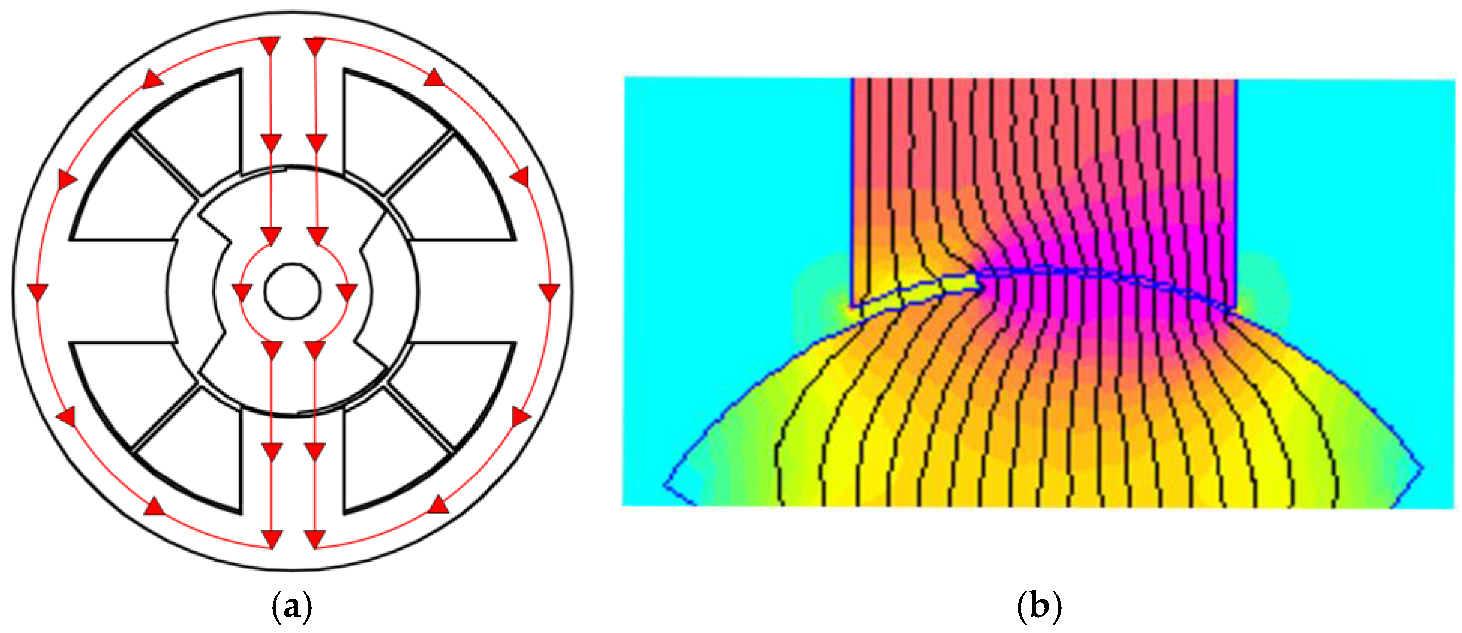
In the stepper rotor-type, the rotor is divided into two parts to create a “step”, as illustrated in Figure 3. By doing this, a non-uniform air gap between the stator and rotor can be formed; thus the torque profile can be modified to eliminate the torque dead zone. Figure 4 shows the flux path of the proposed motor.
2.2. Proposed Hybrid 4/4 SRM
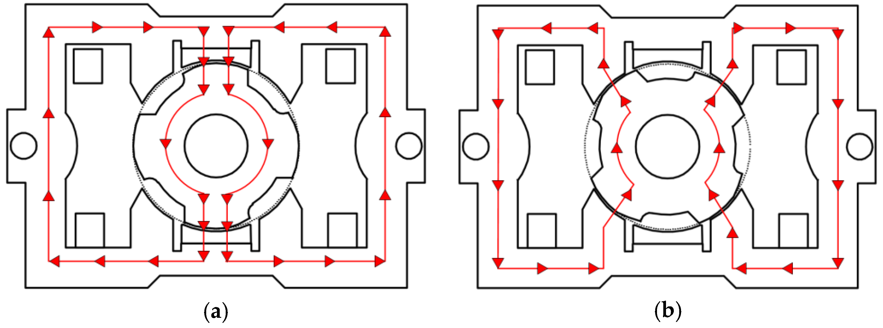
As described above, in hybrid single-phase 4/4 SRMs, PMs are utilized to solve the torque dead zone problem. The PMs act to park the rotor, returning the position to the initial rotor position at every self-start. Because of the presence of PMs, there are two kinds of flux flowing in the motor, the PM flux, which is used when there is no excitation, and the winding flux, which flows during phase excitation, as shown in Figure 5. Furthermore, the non-uniform air gap is also used here to modify the torque characteristics, as there is a negative torque region. The difference between using the uniform and non-uniform air gap is described in the next section.
3. Analysis of 4/2 and 4/4 SRMs
Unlike the 4/2 SRM, the hybrid 4/4 SRM has a rectangular structure to ease the embedding of the PM into the stator. Therefore, the size of the motor is slightly different, although both have the same stack length. The detailed parameters of the motor, including the non-uniform air gap, can be seen in Table 1.
3.1. Flux-Linkage Characteristics
By knowing the flux-linkage profile, the output torque of a SRM can be predicted. Figure 6, Figure 7 and Figure 8 show the comparison of the conventional and proposed motors. In Figure 6, it can be seen that there is a region in a conventional 4/2 SRM in which the flux linkage does not have any rate of change, which means that, in this region, no torque is produced. However, this problem can be fixed by utilizing a non-uniform air gap and wide rotor pole arc to eliminate the torque dead zone and make the positive torque region larger. In the 4/2 SRM, the difference between both air-gap types is considerably large, as the positive region is now almost twice as large as that of the conventional SRM.
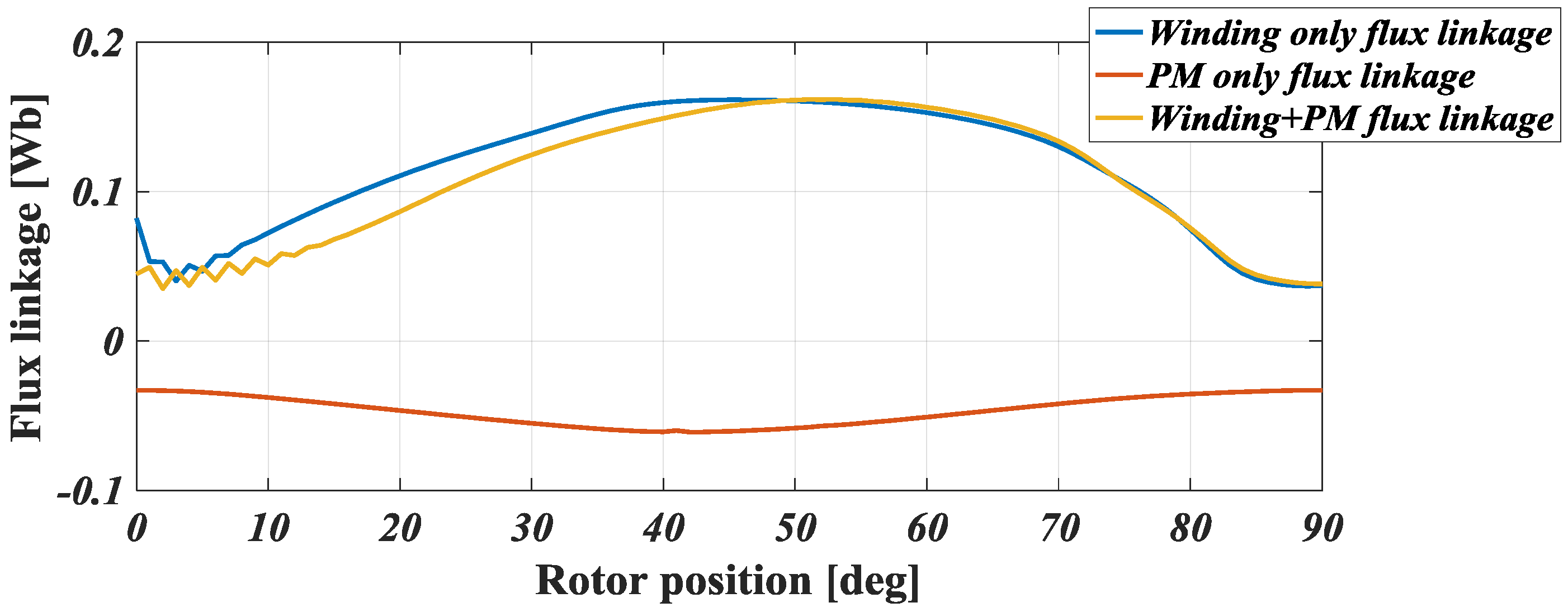
In the case of the hybrid 4/4 SRM, the total flux linkage that is acting inside the motor during excitation is the addition of the winding flux and PM flux. Although the winding flux can be controlled by phase excitation, the PM flux is always present. It can be seen in Figure 7 and Figure 8 that the starting point of the decreasing flux has been moved slightly to the right, thus proving that the non-uniform air-gap rotor can widen the positive-torque region. The rising slope area of the flux linkage has been extended. How it affects the torque profile is explained in the next section.
3.2. Torque Characteristics
As explained before, that the flux-linkage profile of a SRM can predict the output torque of the motor, their relationship can be explained by the following formula:
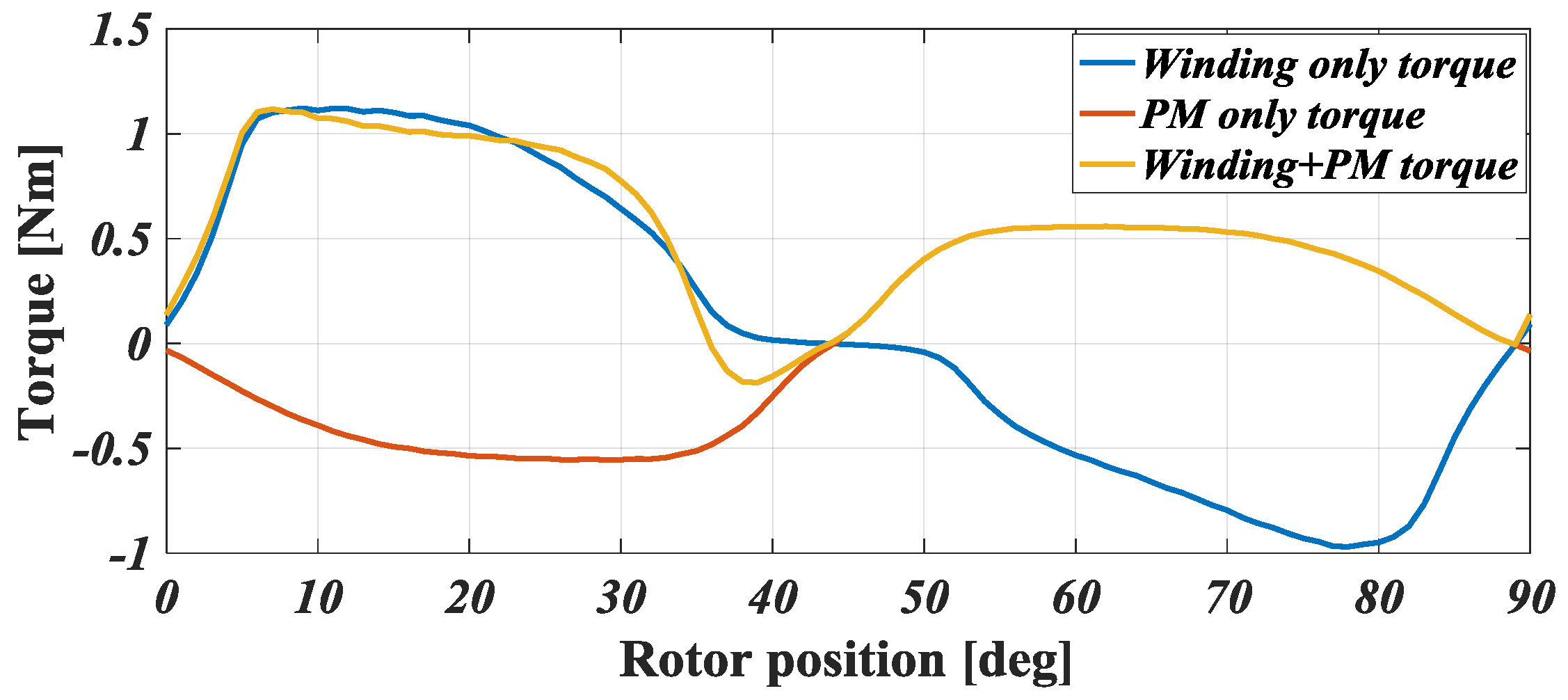
where is the instantaneous torque at phase current and rotor position , while is the flux linkage. Figure 9, Figure 10 and Figure 11 show the torque comparison of the proposed motors. In Figure 9, the continuous torque of the 4/2 SRM can be examined. Here, the phase commutation is considered; thus the negative torque is not shown. The torque dead zone is present in the continuous torque of the conventional motor. However, in the proposed 4/2 SRM, the torque zone has clearly been eliminated. It may seem that the proposed motor produces less output torque, but in fact the output is similar. The maximum and minimum torques of the conventional and proposed 4/2 SRMs are 1.6/0 Nm and 0.82/0.36 Nm with wider positive-torque area, respectively. Therefore, the outputs for each motor are approximately 0.696 Nm and 0.68 Nm with less torque ripple in the proposed motor, which is more preferable in terms of running stability in high-speed applications. In the case of the hybrid 4/4 SRM, referring to its flux-linkage profiles above, there is a negative-torque region as a result of the addition of winding torque and PM torque, as can be seen in Figure 10. The phase commutation in this motor happens at the meeting point of the winding and PM torques. However, the negative-torque region exists before commutation between the phase, and this may cause some problems, such as the rotor rotating backward instead of forward during operation. To solve this, the non-uniform-air-gap rotor is utilized, and, as shown in Figure 11, the positive-torque area widens and the negative-torque area is eliminated. One important point to be noted when designing hybrid SRMs with PMs is that the starting torque of this type of motor needs to be higher than the cogging torque caused by the PMs in order to start the operation.
The torque ripple is considerably lower in the modified structures, which verifies the effectiveness of the non-uniform air gap. For a clearer understanding, the numerical comparison is presented in Table 2. The torque ripple, , can be calculated by using the formula below:
where is the maximum torque, is the minimum torque, and is the average torque in one cycle.
4. Experimental Results
4.1. Prototypes
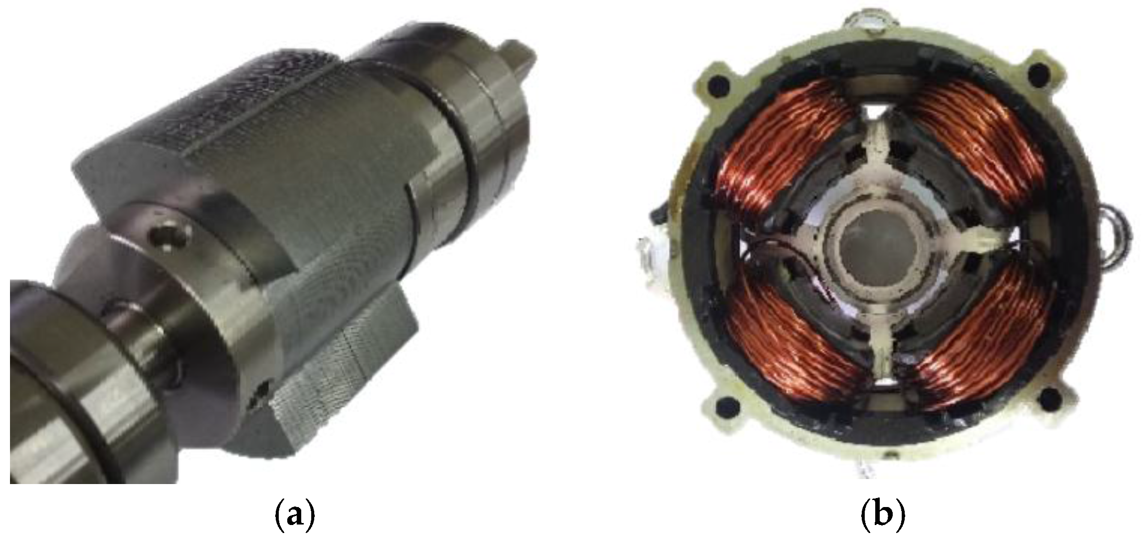
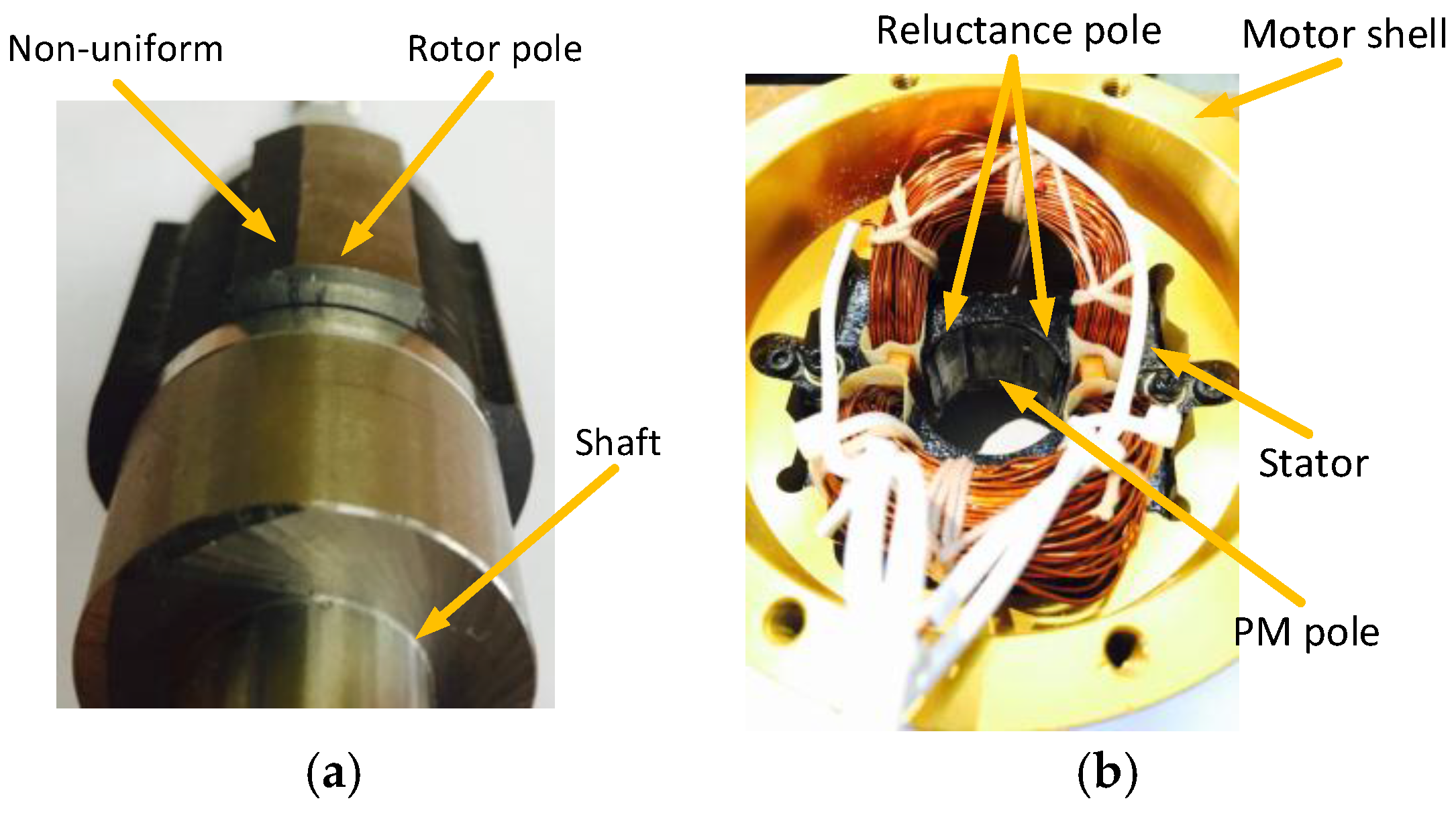
To further verify the validity of the proposed motors, prototypes were designed and manufactured. Figure 12 and Figure 13 show the manufactured prototype of 4/2 and hybrid 4/4 SRMs, respectively. It can be seen clearly that the rotor of the 4/2 SRM adopts the stepper structure, and the rotor of the hybrid 4/4 SRM also implements the non-uniform air gap.
4.2. Experiments
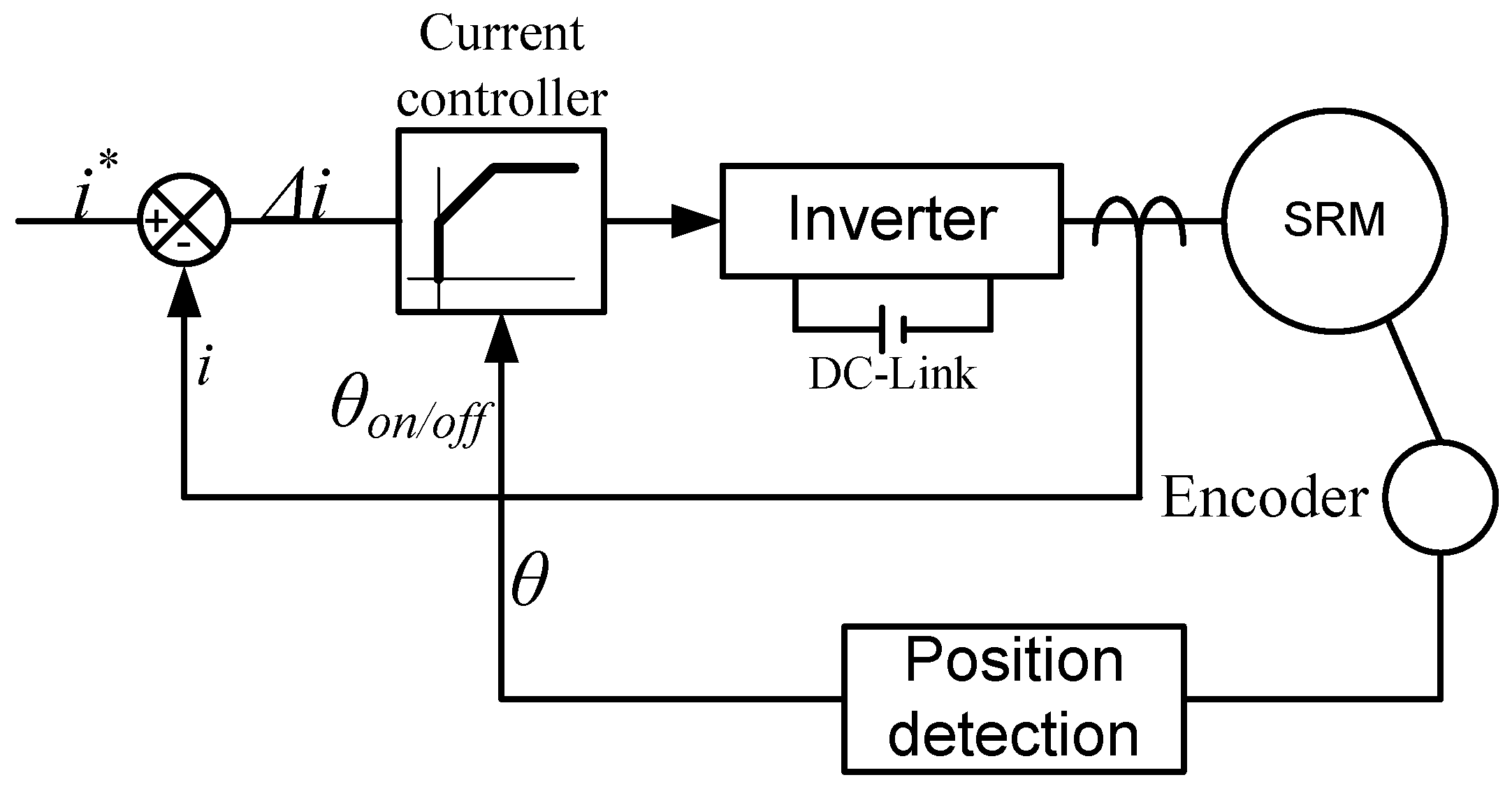
The prototype motor was coupled to a dynamometer to control the load torque and power analyzed to measure the active power. The main controller used a Texas Instrument (TI) digital signal processor (DSP) TMS320F28027. Figure 14 shows the test platform, which includes the dynamometer, coupling, the proposed motor, a jig to hold the motor, and a controller. A simple control scheme used in this experiment is described in Figure 15.
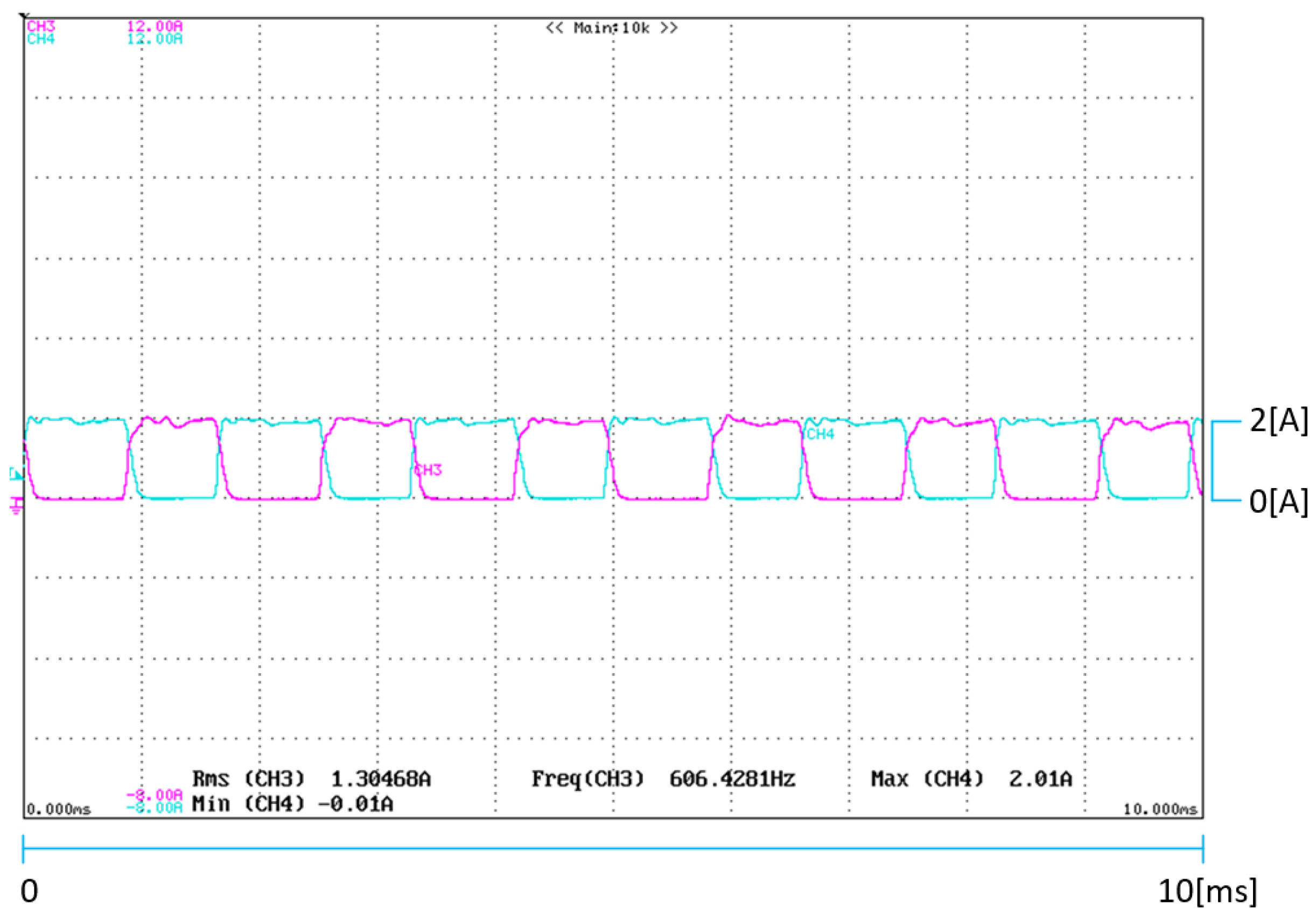
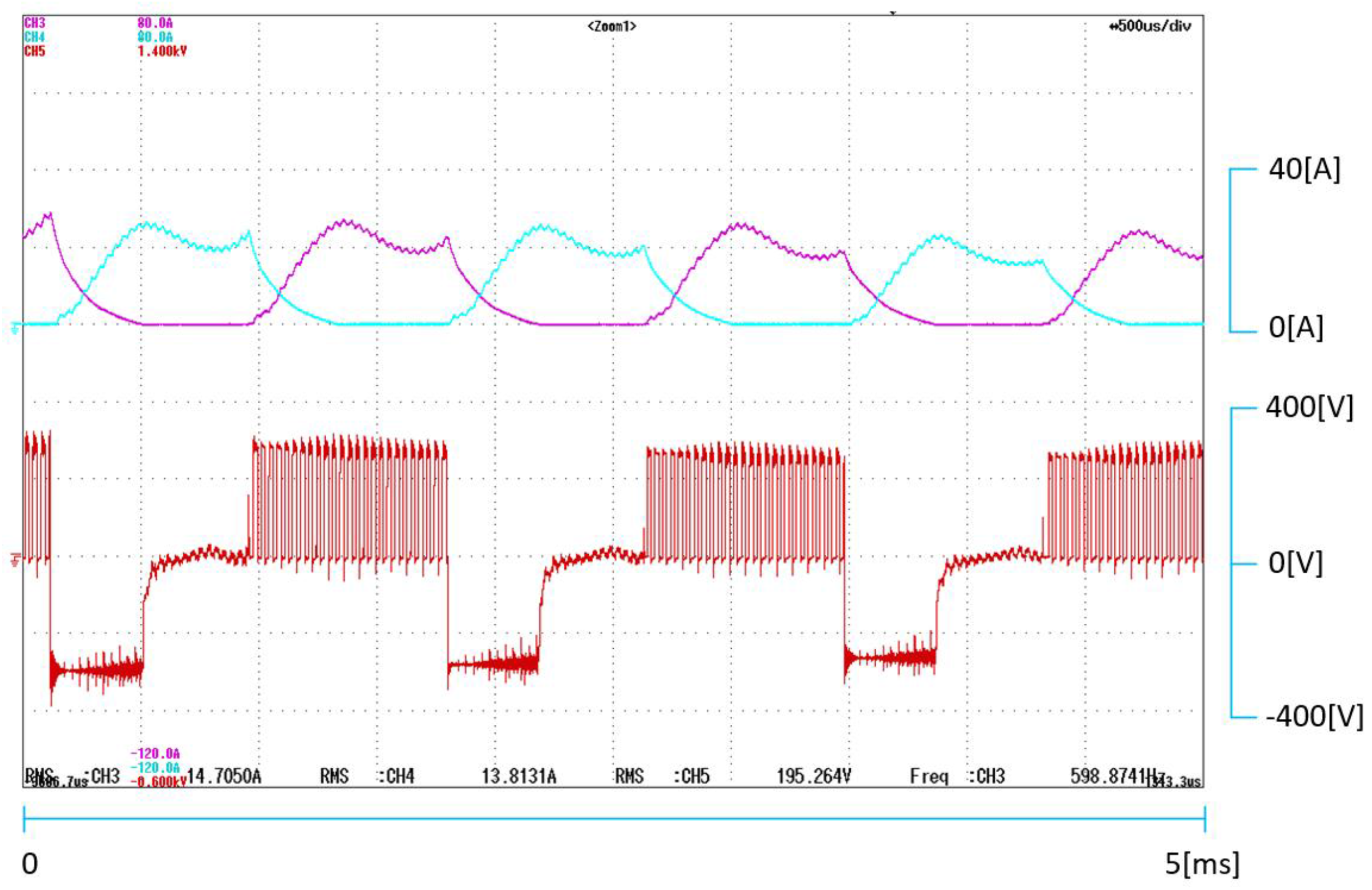
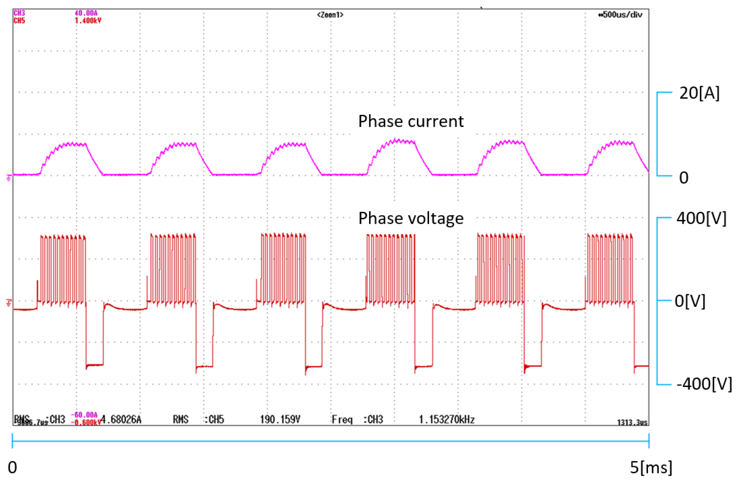
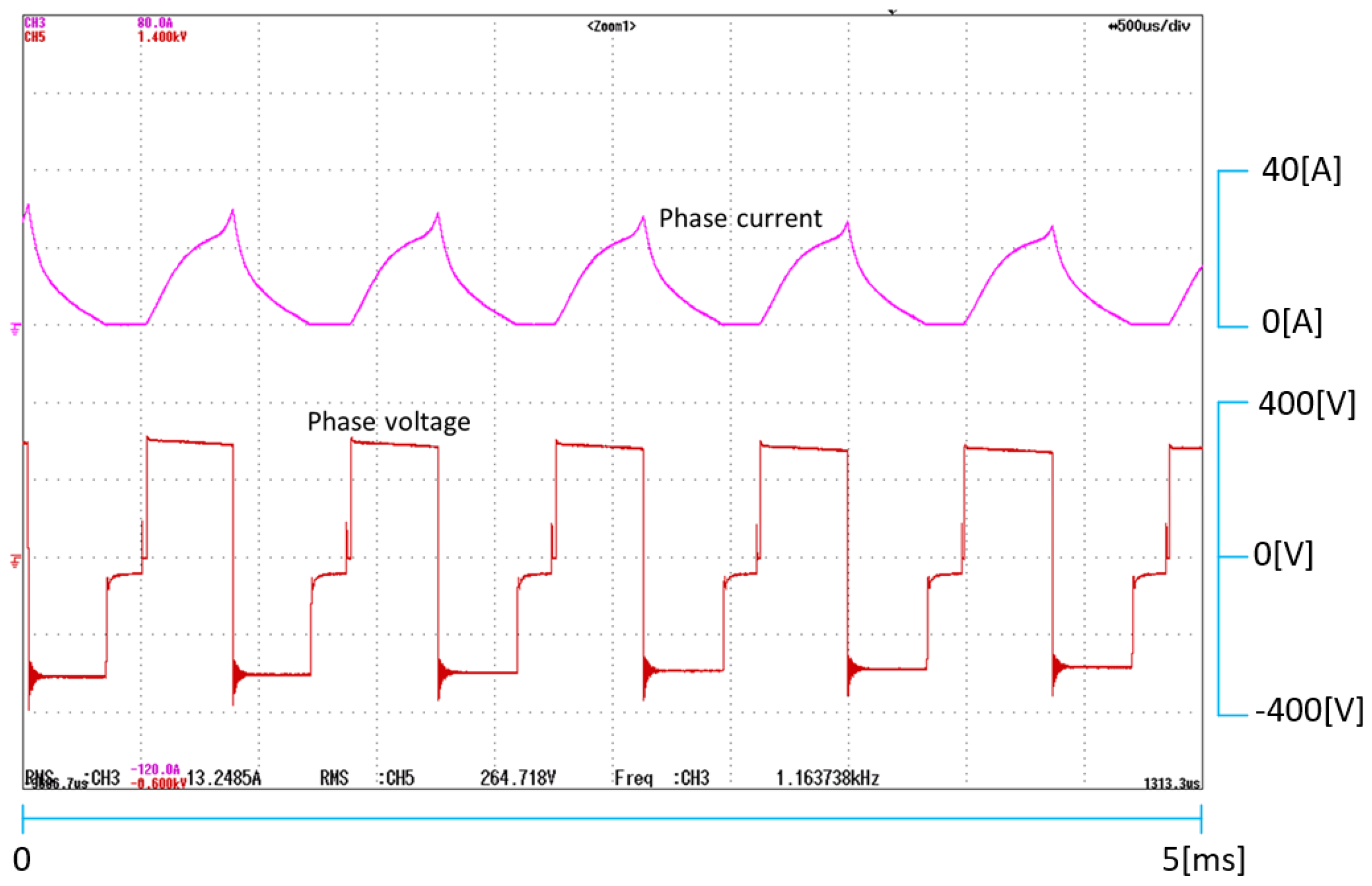
In the experiment, the proposed SRMs were operated in the constant-torque region. Figure 16 and Figure 17 show the experimental result of the proposed 4/2 SRM without and with a rated load at the rated speed of 18,000 rpm. The experimental results of the proposed hybrid 4/4 SRM are shown in Figure 18 and Figure 19. Because of the current limiter in the control scheme, the current can be limited under the current command, and as a result, the current can be controlled. As can be seen in the figures, there was no current overshoot. The phase voltage waveform may describe the control method that is used for the phase excitation. In Figure 17 and Figure 18, the phase voltage waveforms are similar to a pulse-width modulation (PWM) signal. This shows the current limiter method by utilizing a hysteresis band to limit the current. In order to keep the current under the set limit, the phase voltage was turned on and off. However, Figure 19 shows an exception. Here, instead of using current control, a turn-on/off angle control was used. A longer turn on time allows more current to flow, which helps the motor to develop the desired performance with a high speed. The rated torques of the 4/2 and hybrid 4/4 SRMs are 0.68 and 0.40 Nm, respectively.
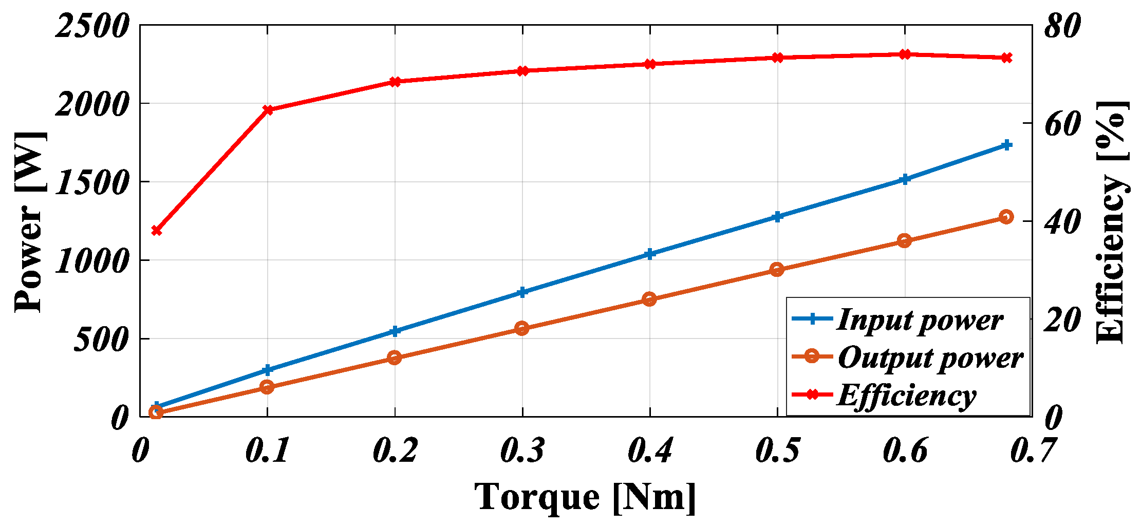
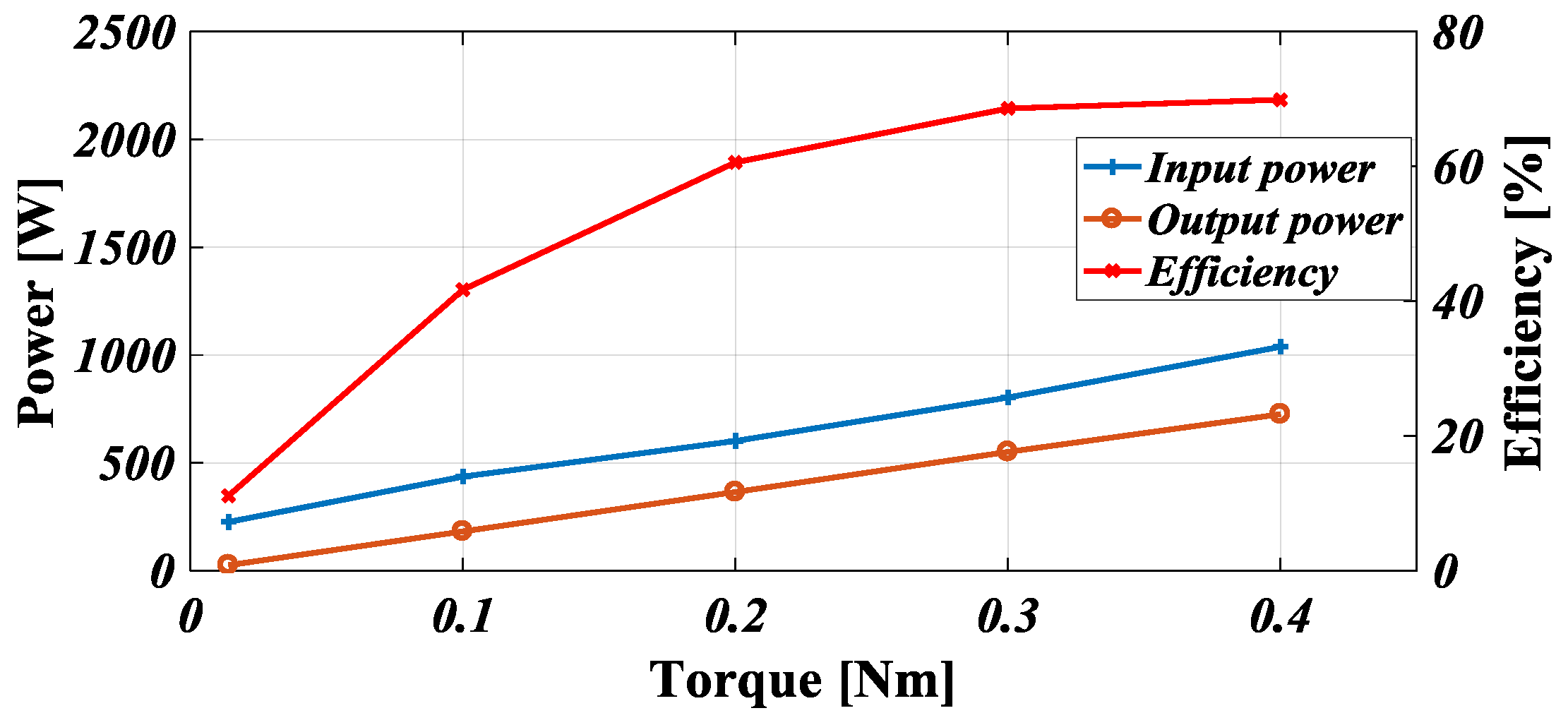
Finally, the performance curves of both proposed motors are shown in Figure 20 and Figure 21. To understand these figures, particularly the efficiency curve, the comprehension of the losses in SRM has to be understood first. Generally, the losses in electric machines are the copper loss, iron loss, friction and windage loss, and stray load loss [10]. The copper loss is caused by the resistance of the stator winding, while the iron loss is the summation of hysteresis and eddy current losses, which happen in the motor core. These losses vary according to the rotating speed and load. Power is proportional to the torque and speed. The results presented in Figure 20 and Figure 21 were obtained by keeping the motor speed constant at the respective rated speed and changing the load. It can be seen that the power increases with the load torque. The efficiency is also shown to increase and reaches its peak at the rated load. As explained before, the ratings of the motors are different, and thus simple comparison parameters cannot be used. The comparison is done by considering its per-weight unit, as can be seen in Table 3.
Both motors are designed to have the same rated speed but a different rated torque; thus they have a different output power. However, according to the per-weight unit used to justify the comparison, the 4/2 and hybrid 4/4 SRMs perform similarly, but the former has a better efficiency. The proposed hybrid 4/4 SRM suffers higher torque ripple compared to the 4/2 SRM; therefore a greater air-gap length is required, which corresponds to the lower efficiency.
5. Conclusions
This paper deals with the comparison between high-speed two-phase 4/2 and single-phase hybrid 4/4 SRMs. Both motors are advantageous as high-speed motor drives because of their simple structure and power circuit, but their practical application is limited because of the presence of the torque dead zone, which makes them lack the self-start capability. In this paper, the solution by implementing a non-uniform-air-gap rotor is presented. A wide-stepper rotor-type is utilized in the proposed 4/2 SRM. As a result, the positive-torque region is widened, and the torque dead zone is eliminated. In the proposed 4/4 SRM, the non-uniform air gap is also achieved by modifying the rotor structure. A shift to the right of the falling flux point can be seen, which confirms the viability of the proposed rotor. Lastly, performances of both proposed motors are compared. It can be seen that although the ratings of the hybrid 4/4 SRM are lower compared to those of the 4/2 SRM, when the parameters are compared according to their weight value, both result in a similar performance, with the 4/2 SRM having a slightly higher efficiency. This per-weight unit is used because the motors have different ratings. The lower efficiency in the hybrid 4/4 SRM-type is due to the wider air gap between the stator and rotor that was designed to increase the stability in the operation of the machine, as it has a higher torque ripple than the 4/2 SRM. The results have been verified through simulation and experiments.
Acknowledgments
This work was supported by the Human Resources Program in Energy Technology of the Korea Institute of Energy Technology Evaluation and Planning (KETEP) granted financial resource from the Ministry of Trade, Industry & Energy, Republic of Korea (No. 20164010200940).
Author Contributions
Grace Firsta Lukman analyzed the data and wrote the paper; Pham Trung Hieu designed the 4/2 SRM and performed the experiments; Kwang-Il Jeong designed the hybrid 4/4 SRM and performed the experiments; Jin-Woo Ahn contributed as an advisor for both the experiments and the paper.
Conflicts of Interest
The authors declare no conflict of interest.
References
- Krishnan, R. Switched Reluctance Motor: Modeling, Simulation, Analysis, Design, and Applications; CRC Press: Boca Raton, FL, USA, 2001. [Google Scholar]
- Lee, D.-H.; Ahn, J.-W. Performance of High-Speed 4/2 Switched Reluctance Motor. J. Electr. Eng. Technol. 2011, 6, 640–646. [Google Scholar] [CrossRef]
- Jeong, K.-I.; Lee, D.-H.; Ahn, J.-W. Performance and design of a novel single-Phase hybrid switched reluctance motor for hammer breaker application. In Proceedings of the 2017 20th International Conference on Electrical Machines and Systems (ICEMS), Sydney, Australia, 11–14 August 2017. [Google Scholar]
- Torok, V.; Loreth, K. The world’s simplest motor for variable speed control? The Cyrano motor, a PM-biased SR-motor of high torque density. In Proceedings of the 5th European Conference on Power Electronics and Applications, Brighton, UK, 13–16 September 1993; Volume 6, pp. 44–48. [Google Scholar]
- Torok, V. Electric Motor with Combined Permanent and Electromagnets. U.S. Patent US5345131, 6 September 1994. [Google Scholar]
- Torok, V. Self-Starting Electric Brushless Motor Having Permanent Magnet and Reluctance Poles. U.S. Patent US6204587, 20 March 2001. [Google Scholar]
- Lee, D.-H.; Ahn, S.-Y.; Ahn, J.-W. Advanced Torque Control Scheme for the High Speed Switched Reluctance Motor. Available online: http://jchemed.chem.wisc.edu/Journal/Issues/2005/Nov/abs1601.html (accessed on 26 January 2018).
- Hieu, P.T.; Lee, D.-H.; Ahn, J.-W. Design and Operation Characteristics of Novel 2-Phase 6/5 Switched Reluctance Motor. J. Electr. Eng. Technol. 2014, 9, 2194–2200. [Google Scholar] [CrossRef]
- Minh Khoi, H.K. Design and Control of a High Speed 4/2 SRM for Blower Application. Master’s Thesis, Kyungsung University, Busan, Korea, 2010. [Google Scholar]
- Raulin, V.; Radun, A.; Husain, I. Modeling of losses in switched reluctance machines. IEEE Trans. Ind. Appl. 2004, 40, 1560–1569. [Google Scholar] [CrossRef]
Figure 1.
Structure of conventional (a) 4/2 switched reluctance motor (SRM), and (b) Cyrano-type 4/4 SRM.
Figure 1.
Structure of conventional (a) 4/2 switched reluctance motor (SRM), and (b) Cyrano-type 4/4 SRM.

Figure 2.
Torque dead zone.
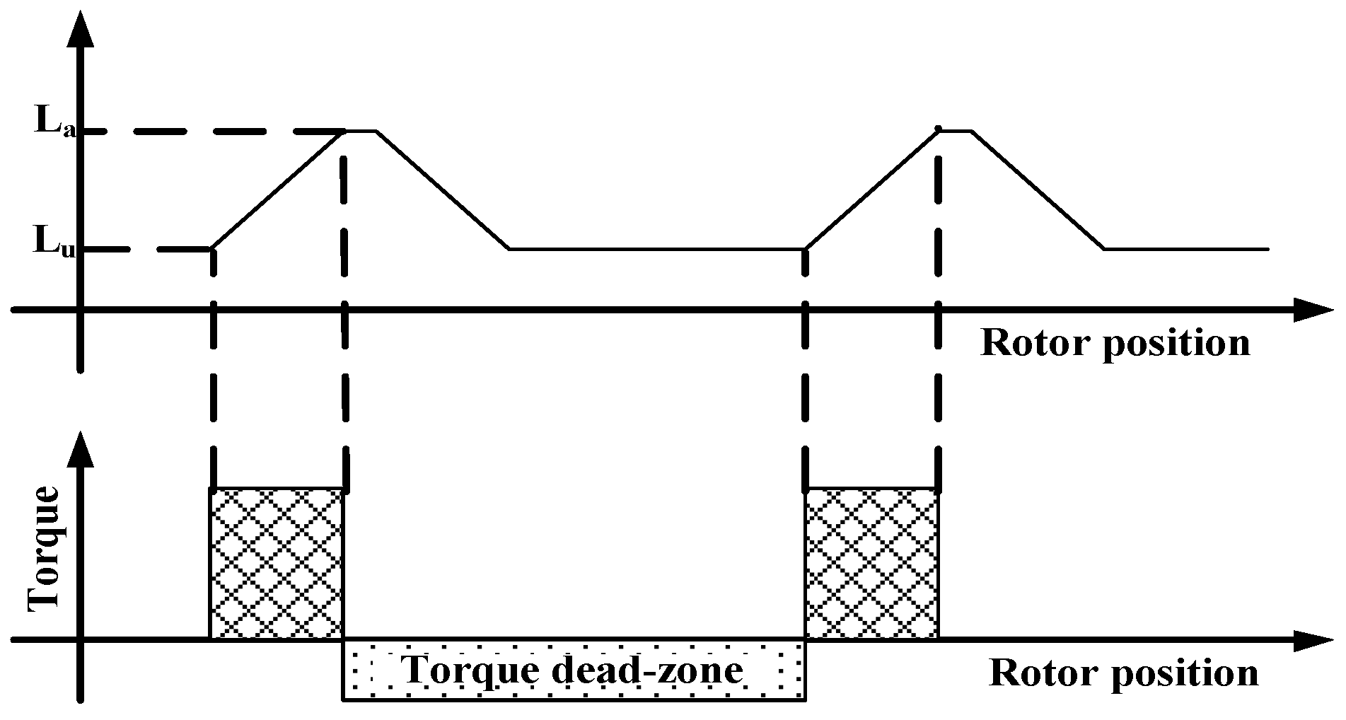
Figure 3.
Stepper rotor-type.
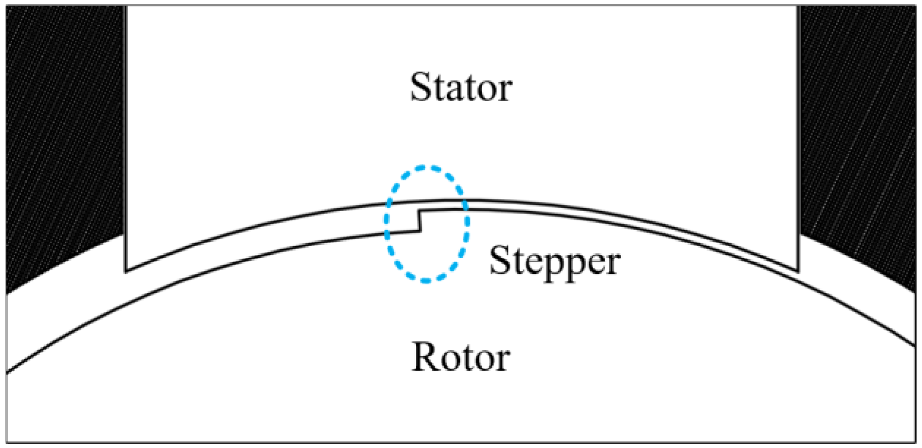
Figure 4.
The flux path in proposed 4/2 switched reluctance motor (SRM): (a) illustration; (b) detailed air-gap flux.
Figure 4.
The flux path in proposed 4/2 switched reluctance motor (SRM): (a) illustration; (b) detailed air-gap flux.

Figure 5.
Flux path in hybrid 4/4 switched reluctance motor (SRM) (a), permanent magnet (PM) flux, and (b) winding flux.
Figure 5.
Flux path in hybrid 4/4 switched reluctance motor (SRM) (a), permanent magnet (PM) flux, and (b) winding flux.

Figure 6.
Flux-linkage comparison between conventional and proposed 4/2 switched reluctance motor (SRM).
Figure 6.
Flux-linkage comparison between conventional and proposed 4/2 switched reluctance motor (SRM).
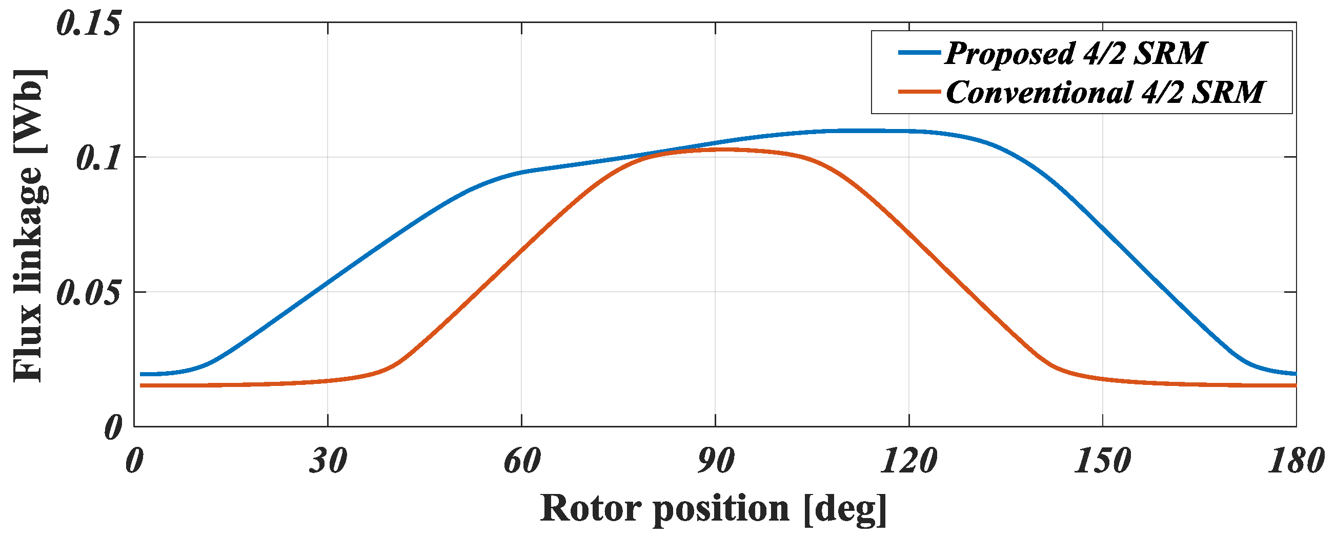
Figure 7.
Flux linkage of the uniform-air-gap hybrid 4/4 switched reluctance motor (SRM).
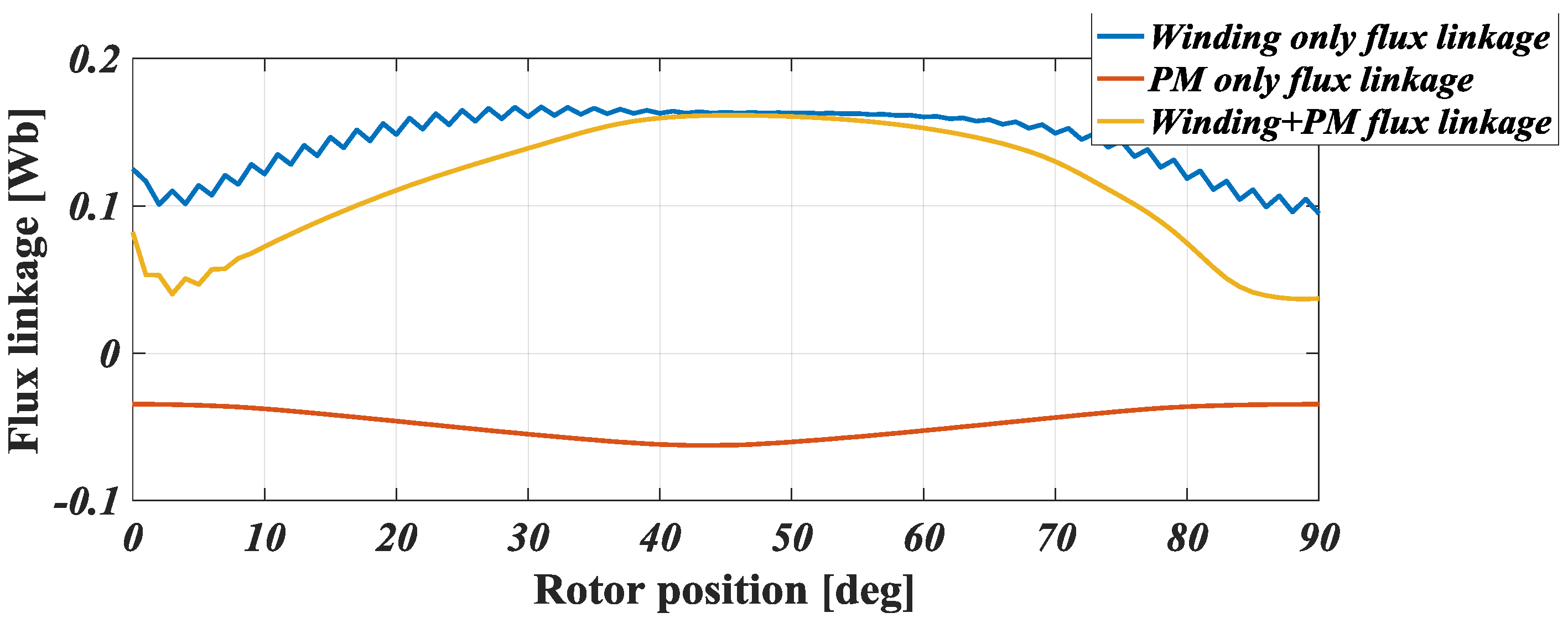
Figure 8.
Flux linkage of the non-uniform-air-gap hybrid 4/4 switched reluctance motor (SRM).

Figure 9.
Continuous torque comparison of proposed and conventional 4/2 switched reluctance motors (SRMs).
Figure 9.
Continuous torque comparison of proposed and conventional 4/2 switched reluctance motors (SRMs).

Figure 10.
Phase torque profile of the uniform-air-gap hybrid 4/4 switched reluctance motor (SRM).

Figure 11.
Phase torque profile of the non-uniform-air-gap hybrid 4/4 switched reluctance motor (SRM).
Figure 11.
Phase torque profile of the non-uniform-air-gap hybrid 4/4 switched reluctance motor (SRM).
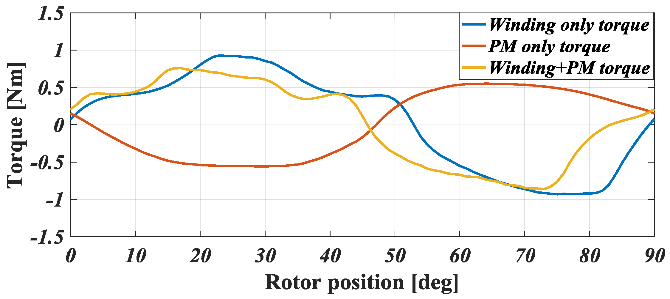
Figure 12.
Prototype of the proposed 4/2 switched reluctance motor (SRM): (a) rotor, and (b) stator.
Figure 12.
Prototype of the proposed 4/2 switched reluctance motor (SRM): (a) rotor, and (b) stator.

Figure 13.
Prototype of the proposed hybrid 4/4 switched reluctance motor (SRM): (a) rotor, and (b) stator.
Figure 13.
Prototype of the proposed hybrid 4/4 switched reluctance motor (SRM): (a) rotor, and (b) stator.

Figure 14.
Test platform.
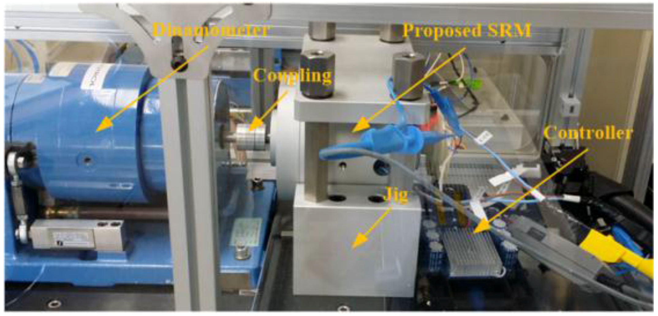
Figure 15.
Control scheme of high-speed switched reluctance motor (SRM).

Figure 16.
Experimental result of the 4/2 switched reluctance motor (SRM) at 18,000 rpm with no load.
Figure 16.
Experimental result of the 4/2 switched reluctance motor (SRM) at 18,000 rpm with no load.

Figure 17.
Experimental result of the 4/2 switched reluctance motor (SRM) at 18,000 rpm and 0.68 Nm.
Figure 17.
Experimental result of the 4/2 switched reluctance motor (SRM) at 18,000 rpm and 0.68 Nm.

Figure 18.
Experimental results of the 4/4 switched reluctance motor (SRM) at 18,000 rpm with no load.
Figure 18.
Experimental results of the 4/4 switched reluctance motor (SRM) at 18,000 rpm with no load.

Figure 19.
Experimental results of the 4/4 switched reluctance motor (SRM) at 18,000 rpm and 0.40 Nm.
Figure 19.
Experimental results of the 4/4 switched reluctance motor (SRM) at 18,000 rpm and 0.40 Nm.

Figure 20.
Performance of the proposed 4/2 switched reluctance motor (SRM).

Figure 21.
Performance of the proposed hybrid 4/4 switched reluctance motor (SRM).


Table 1.
Parameters of the proposed switched reluctance motors (SRMs).
| Parameter | 4/2 SRM | Hybrid 4/4 SRM |
|---|---|---|
| Number of phases | 2 | 1 |
| Stator outer diameter (mm) | 100 | - |
| Stator width (mm) | - | 58 |
| Stator length (mm) | - | 78 |
| Rotor outer diameter (mm) | 45 | 34 |
| Air-gap length (mm) | 0.25/0.8 | 0.5/1.2 |
| Stack length (mm) | 30 | ← |
| Shaft diameter | 10 | 13 |
Table 2.
Torque ripple comparison of the proposed switched reluctance motors (SRMs).
| Parameter | Conventional 4/2 SRM | Proposed 4/2 SRM | Conventional Hybrid 4/4 SRM | Proposed Hybrid 4/4 SRM |
|---|---|---|---|---|
| Maximum torque (Nm) | 1.597 | 0.8214 | 1.1175 | 0.9289 |
| Minimum torque (Nm) | 0 | 0.3582 | -0.1870 | 0.1597 |
| Average torque (Nm) | 0.6960 | 0.6806 | 0.6302 | 0.5579 |
| Torque ripple (%) | 229.454 | 68.058 | 206.998 | 137.874 |
Table 3.
Performance comparison of the proposed switched reluctance motors (SRMs)
| Parameter | 4/2 SRM | Hybrid 4/4 SRM |
|---|---|---|
| Rated speed (rpm) | 18,000 | ← |
| Rated torque (Nm) | 0.68 | 0.40 |
| Output power (W) | 1272 | 725.4 |
| Torque/weight (Nm/kg) | 0.58 | ← |
| Power/weight (W/kg) | 1,088 | 1,048 |
| Efficiency (%) | 73.3 | 70 |
© 2018 by the authors. Licensee MDPI, Basel, Switzerland. This article is an open access article distributed under the terms and conditions of the Creative Commons Attribution (CC BY) license (http://creativecommons.org/licenses/by/4.0/).
Share and Cite
MDPI and ACS Style
Lukman, G.F.; Hieu, P.T.; Jeong, K.-I.; Ahn, J.-W. Characteristics Analysis and Comparison of High-Speed 4/2 and Hybrid 4/4 Poles Switched Reluctance Motor. Machines 2018, 6, 4. https://doi.org/10.3390/machines6010004
AMA Style
Lukman GF, Hieu PT, Jeong K-I, Ahn J-W. Characteristics Analysis and Comparison of High-Speed 4/2 and Hybrid 4/4 Poles Switched Reluctance Motor. Machines. 2018; 6(1):4. https://doi.org/10.3390/machines6010004
Chicago/Turabian StyleLukman, Grace Firsta, Pham Trung Hieu, Kwang-Il Jeong, and Jin-Woo Ahn. 2018. "Characteristics Analysis and Comparison of High-Speed 4/2 and Hybrid 4/4 Poles Switched Reluctance Motor" Machines 6, no. 1: 4. https://doi.org/10.3390/machines6010004
Note that from the first issue of 2016, this journal uses article numbers instead of page numbers. See further details here.