Modal Coupling in Presence of Dry Friction


Department of Industrial Engineering, University of Salerno, Via Giovanni Paolo II, 132, 84084 Fisciano, Italy
*
Author to whom correspondence should be addressed.
Machines 2018, 6(1), 8; https://doi.org/10.3390/machines6010008
Submission received: 22 January 2018
/
Revised: 23 February 2018
/
Accepted: 24 February 2018
/
Published: 27 February 2018
(This article belongs to the Special Issue Vibration Control Systems)
Abstract
:In this paper, we analyze the behavior of a single pad system in the presence of dry friction. The goal is to investigate the path that leads a stable mechanical system to unstable behavior. In doing so, we studied the behavior of a discrete three DOF model, a continuous model and a finite element model of the pad. The numerical results are consistent with the experimental investigation conducted on a brake disk for railway application.
1. Introduction
The aim of this study is to investigate the influence of dry friction on the emergence of forms of instability for stable systems. The presence of friction can lead a stable mechanical system to unstable behavior due to geometrical instability. Geometrically-induced instability or kinematic instability emphasizes the physical parameters of the system along with the coefficient of friction as the reason for the squeal phenomenon. Such instability can result in unwanted vibration, e.g., squeal noise for disk brakes, or wanted vibration, e.g., musical string instruments. Since the early 20th century, many investigators have examined the problem with experimental, analytical and computational techniques, but there is still no definitive solution to eliminate this phenomenon [1].
1.1. Automotive Brake Squeal
In recent experimental work, it has been observed that the position of the center of pressure at the brake pad/disc contact area has an influence on the onset of brake squeal [2]. The effects of the main parameters such as the coefficient of friction and the attack angle are studied to understand their influences on the stability of the system. In fact, for a given formulation, disc pad porosity can affect friction, wear and squeal [3]. Based on customer’s needs for noise-free brakes, car manufactures are increasingly installing damping kits in their braking systems. However, the installation of the damping kits may excessively increase softness in the brake system, by loosening the stroke feeling of a brake pedal and increasing compressibility over durability [4]. Brake shims are widely used to reduce the squeal occurrence rate. In particular, laminated shims can effectively suppress squeal via viscoelastic damping of an adhesive layer [5]. According to studies conducted by Festjens, shims are almost uniquely in their normal direction in brake systems. The studies that focus on the added damping and stiffening induced by the viscoelastic materials reveal that certain eigenmodes of the viscoelastic shims can reveal instabilities that would not exist without them [6]. Fulco underlined the importance of the contact stiffness between the baking plate and the piston or caliper on the squeal noise generation and how the shim improves this factor [7]. It has however been shown by Spelsberg-Korspeter, analytically and experimentally, that the stiffness properties of the disc are important and that splitting of double modes of the disc has a stabilizing effect [8]. For this reason, optimization studies for brake squeals are conducted to minimize the strain energy of vibrating pads with constrained layer damping. To achieve such an effect, finite element analysis and experiments are done, and the assumed-coupling mode method is used to solve such a problem [9]. In most computer-aided engineering (CAE) simulations of brake noise, shims are modeled as thin sheets of steel or are not modeled at all. This introduces some inaccuracy because the damping effect and flexibility of the rubber and adhesive material are ignored [10]. Another aspect when designing mechanical assemblies is assembly tolerance design, a very important issue that must be seriously considered by designers [11,12,13,14]. For Bonnay et al., 2015, two kinds of geometric imperfections must be taken into account separately: the first is “disc thickness variation” as a function of the disc, while the second is the “plateau” as a function of the friction pad. The authors show that the introduction of both kinds of geometrical imperfections has an influence on the dynamic behavior and on mode lock-in (through modification of the eigen-frequencies of the system). The pad mode is mostly influenced by bumping, which modifies the contact localization [15]. Furthermore, Zhang et al., 2017, demonstrated that the pressure angle or the brake force direction have an important influence on the unstable chatter and squeal noise: the greater the pressure angle deviates from the wheel center, the greater the possibility of chatter and squeal noise is, and the possibility of chatter and squeal noise is also increased along with the addition of the friction factor [16]. Zainudin and Abu Bakar investigated squeal occurrences in a disc brake assembly without a thin plate shim for various operating conditions using a drag-type brake dynamometer. The authors identified for the dominant squeal frequencies several shapes of thin plate shim in order to modify the contact pressure distribution on the brake pads [17]. Shimizu et al., 2014, investigated the effects of grease on brake squeal. The results underlined that adhesive (bonded) shims were found to be effective for high frequency squeal (pad bending mode) by increasing damping, while grease is effective for low frequency squeal (pad rigid mode) [18]. Wagner et al., 2014, investigated the use of the asymmetry of the brake rotor in order to split of all double eigenfrequencies of the brake rotor to stabilize the system [19].
1.2. Modal Coupling Effects on Brake Squeal
For Lv and Zhang (2013), disc brake squeal is mainly dependent on modal coupling and influenced by both the friction coefficient and the disc surface run-out (SRO). When disc brake squeal occurs, the time history of sound pressure is consistent with that of the disc vibration [20]. Zhang et al., 2018, studied a flexible pin-on-disk system used to simulate how squeal noise can be generated in frictional contact. The time-varying frictional squeal reappears by introducing a periodic frictional coefficient generated from rotation [21]. Charroyer et al. [22] paid special attention to the role of damping and the associated destabilization paradox in mode-coupling instabilities with planar and rectilinear friction assumptions. The dynamics can become unstable when two modes couple due to the normal and tangential components of the frictional force. A solution is presented by applying shims to brake pads that, as reported by Esgandari and Olatunbosun [10], are capable of suppressing high frequency noise in disc brake units, by adding more damping to the system in the brake pad area, reducing energy transfer between the components, which would cause modal coupling. Overall, the main theories that describe squeal phenomenon ascribe the increase of vibration amplitudes to the stick-slip mechanism or to the geometrical instability of the brake assembly. Both approaches agree that the squeal phenomenon depends, above all, on the variation of the friction force. It was therefore decided to study the behavior of a conservative system in the presence of friction using several models to study the pathways that lead to instability. The form of instability, due to friction, most easily verified is the one associated with squeal occurrence in disk brakes. Therefore, we decided to study the behavior of a simple pin on a circular track. Numerical analyses that can be used to predict instabilities are complex modal analysis [23] and transient dynamic analysis [24]. The authors’ goal is to replicate, through the use of a simplified model, the instability phenomena found during an experimental activity conducted on a disc brake for railway applications [25]. This paper is organized as follows. In Section 2, the scheme of the discrete system is reported with the equation of motion used to study the behavior of the pad system. Section 3 describes the continuous model of the pad and the longitudinal and transversal forms of instability for a varying friction parameter. In Section 4, we report a modal analysis and a transient analysis conducted with Ansys Workbench software on the finite element model of the pad system. Finally, our conclusions about the simulations conducted on our model are presented.
2. Discrete Model Behavior in the Presence of Dry Friction
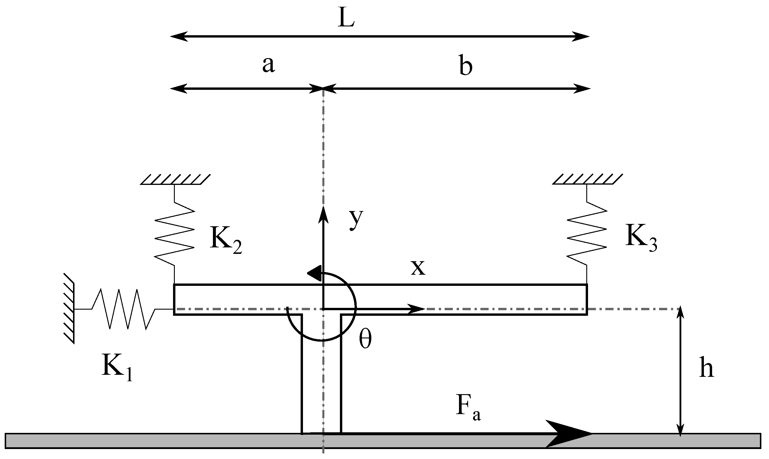
To understand how geometrical instabilities influence the behavior of a mechanical system, we decided to study the system reported in Figure 1, a system that recalls a friction pad. The model is a discrete three-degree of freedom system, subjected to dry friction, free to move in the x and y direction and to rotate around its center of gravity (CG). There are three elastic force-fields at the ends of the horizontal cantilever, while at the contact point of the vertical beam with the ground, there is a force-field due to friction. The assumptions made for this model are no dynamic slip-stick behavior and constant dynamic friction coefficient f. In Equation (1), the equation of motion of the system has been reported. M and represent respectively the mass and the moment of inertia of the system, and , and are the stiffness of the three springs.
The friction force-field, as shown in Equation (2), is a function of the dynamic friction coefficient, which is independent of contact relative velocity and of the closing force.
Therefore, the equation of motion can be rewritten as:
considering a new stiffness matrix. As can be seen from Equation (3), friction coefficient f is present within the new stiffness matrix . For this reason, to prevent the occurrence of instability phenomena, we should verify the influence of the parameter on the eigenvalues of the stiffness matrix, evaluating for which values of the parameter the stiffness matrix will become a non-positive defined matrix.
From Equation (4), the equation of eigenvalues of the stiffness matrix , we achieve Equation (5), which will be verified when one or more eigenvalues of the matrix become negative.
From Equation (5), we note that for specific combinations of physical and geometrical parameters, the system can turn unstable. To assess the influence of these parameters and their combination on the eigenvalues of the system, a preliminary study has been conducted by varying the ratio of the stiffness of the two springs and the position of the vertical element with respect to the horizontal bar .
The values used are reported in Table 1. As is easy to understand, must be always a positive number. When the parameter has a non-positive value, Equation (5) is not verified, and the stiffness matrix will be definite positive.
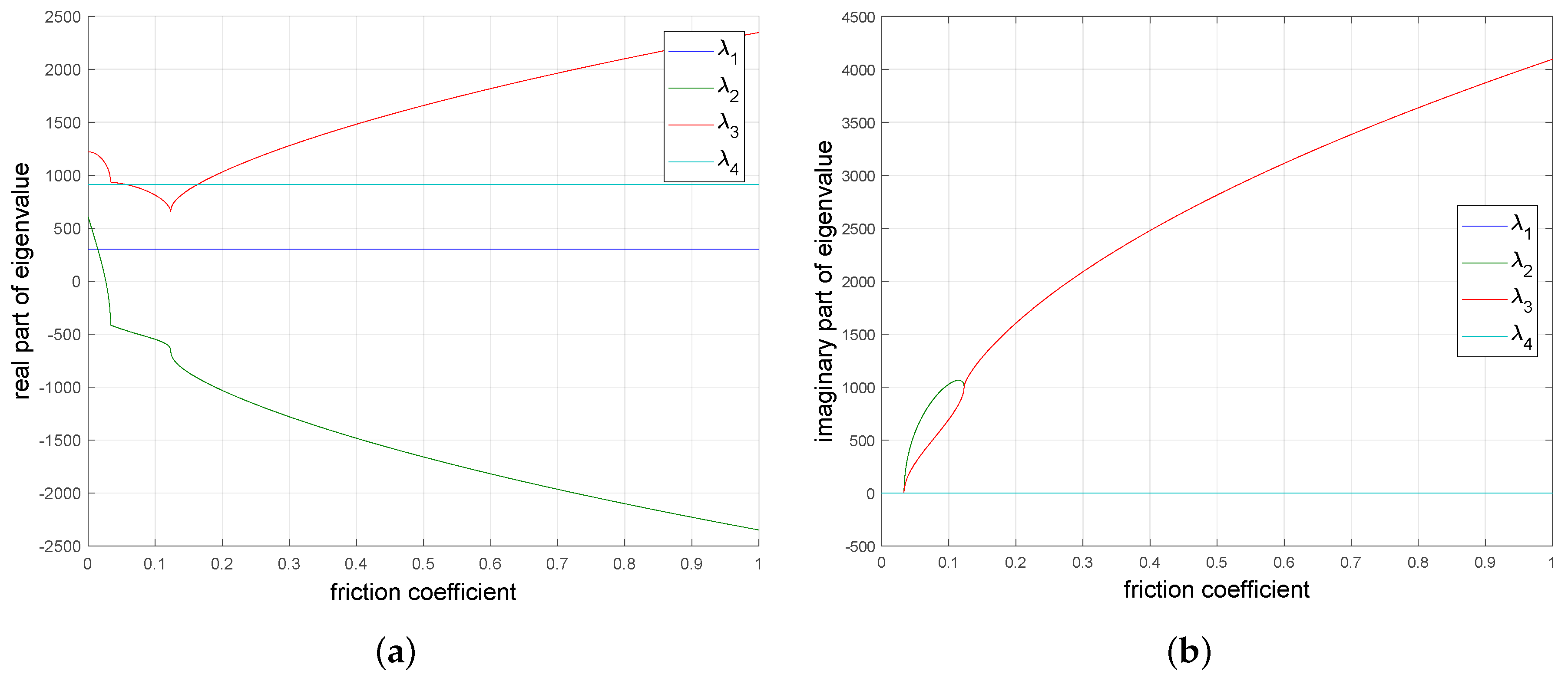
In Figure 2, the eigenvalues of the stiffness matrix are plotted against the friction coefficient values.
As is easy to see from Figure 2a, for the case shown, for , eigenvalues and collide to a single value. Furthermore, increasing the value, it is possible to see how the eigenvalues become definitively negative, certifying the unstable behavior of the system. From Figure 2b, we can appreciate how the imaginary part of the collided eigenvalue splits in two.
3. Continuous Model Behavior in the Presence of Dry Friction
Having analyzed the behavior of the three-degree of freedom system, we decided to study the same system by analyzing it as a continuous system. In Figure 3, we report the dimensions used for the continuous model. For the beam simply supported at both ends by a rotational joint, independently from the instant considered, both the transverse displacements and the bending moment at the extremes must be null as reported in Equations (6) and (7).
From the theory of continuous systems, analyzing longitudinal and transverse vibrations for a beam, we wrote the equations of motion in matrix form of the continuous system as follows:
where and for Equation (8) and and for Equation (9) are the mass and stiffness matrix for the longitudinal and transversal motion of the beam derived from the theory of continuous systems. In case of external forcing, to the equations of motion, we must consider the term that contains Lagrangian components of the active forces. The equations of motion in principal coordinates become:
with Lagrangian components of the active forces, due to forcing agents on the system related to the vibration mode considered. Virtual work of the external forces applied to the system is expressed as a function of the physical coordinates or . Considering the vertical appendix rigid, we can consider the frictional force applied to the center of the horizontal beam. Therefore, at , we consider a frictional force in the longitudinal direction and a moment . Thus, separating the longitudinal vibrations from the transversal ones, we obtain:
Expressing the virtual displacement and virtual rotation in principal coordinates, we obtain:
Therefore, the work performed by the active forces will become:
Equations (17) and (18) are the generic Lagrangian components representing the work that the friction is able to introduce in the generic mode of vibration for the displacement of the single coordinate .
Substituting these matrices in the equations of motion of the system, a new stiffness matrix can be detected as shown in Equations (19) and (20).
In Figure 4 and Figure 5, we reported the trend of the eigenvalues of and , respectively, for a varying friction coefficient.
Examining Figure 4a, in which is reported the real part of the eigenvalue for the longitudinal vibration of the system against the frictional coefficient, we can observe that the first eigenvalue becomes negative for a , indicating that the first longitudinal mode of vibration becomes unstable for that value of friction. The other eigenvalues, being positive, do not lead the system to instability.
Regarding the transverse vibrations, from Figure 5, we can recognize a typical form of dynamical instability. In fact, for , we can recognize flutter instability in Figure 5b. Two eigenvalues, and , collide into a single value, while the real part of the eigenvalue, reported in Figure 5a, assumes the same value, yet of opposite sign. From the results, it is clear that the vertical length of the appendix, closely linked to the value of , will have a strong influence on the tendency to instability of the analyzed system.
4. Analysis of the Finite Element Model
Subsequently, we carried out a finite element method analysis on the model. In this section, we compared the results obtained for a 2D simplified model with those obtained from a 3D model of the pad. Also in this case, the aim is to simulate the interaction between the system and a belt in presence of dry friction. The analyses that allow us to evaluate the forms of instability as a function of friction coefficient are complex modal analysis and transient structural analysis.
4.1. Modal Analysis
For the first analysis, we use data obtained from a previous static analysis to assess the initial state of the system. For the static analysis, the system is bonded at the extremes of the horizontal beam, ensuring a closing force between the vertical beam. In the contact zone between the rigid beam and the rigid disk, dry friction is modeled as Coulomb friction.
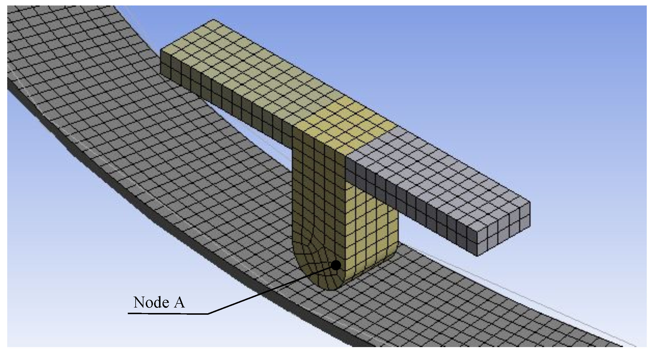
The study of the eigenvalues by performing a modal analysis allows us to determine the eigenfrequencies and the damping ratio for each mode as criteria for stability and squealing. In Design Modeller, the CAD environment of Ansys Workbench, we created the geometry for the modal and transient structural analysis reported after meshing in Figure 6. Material properties, used for the pin and track, were taken from the Engineering Data section.
For both simulations, we considered the track rigid and the pin flexible. Both ends of the horizontal beam were fixed. For the contact zone between the pin and the track, the contact type was changed to frictional. Due to the rigid behavior selected for the track compared to the flexible behavior of the pin, an asymmetric behavior for the frictional contact setting was selected.
The formulation used for the contact setting was augmented Lagrange and a hybrid formulation between pure penalty and normal stiffness. The normal forced push-back is evaluated as , where is the normal stiffness of the contact region and is the contact pressure. We performed a pre-stressed modal analysis to ensure closing force to the system. The first investigation involved several complex modal analyses of the free vibration modes of the system in the presence of dry friction.
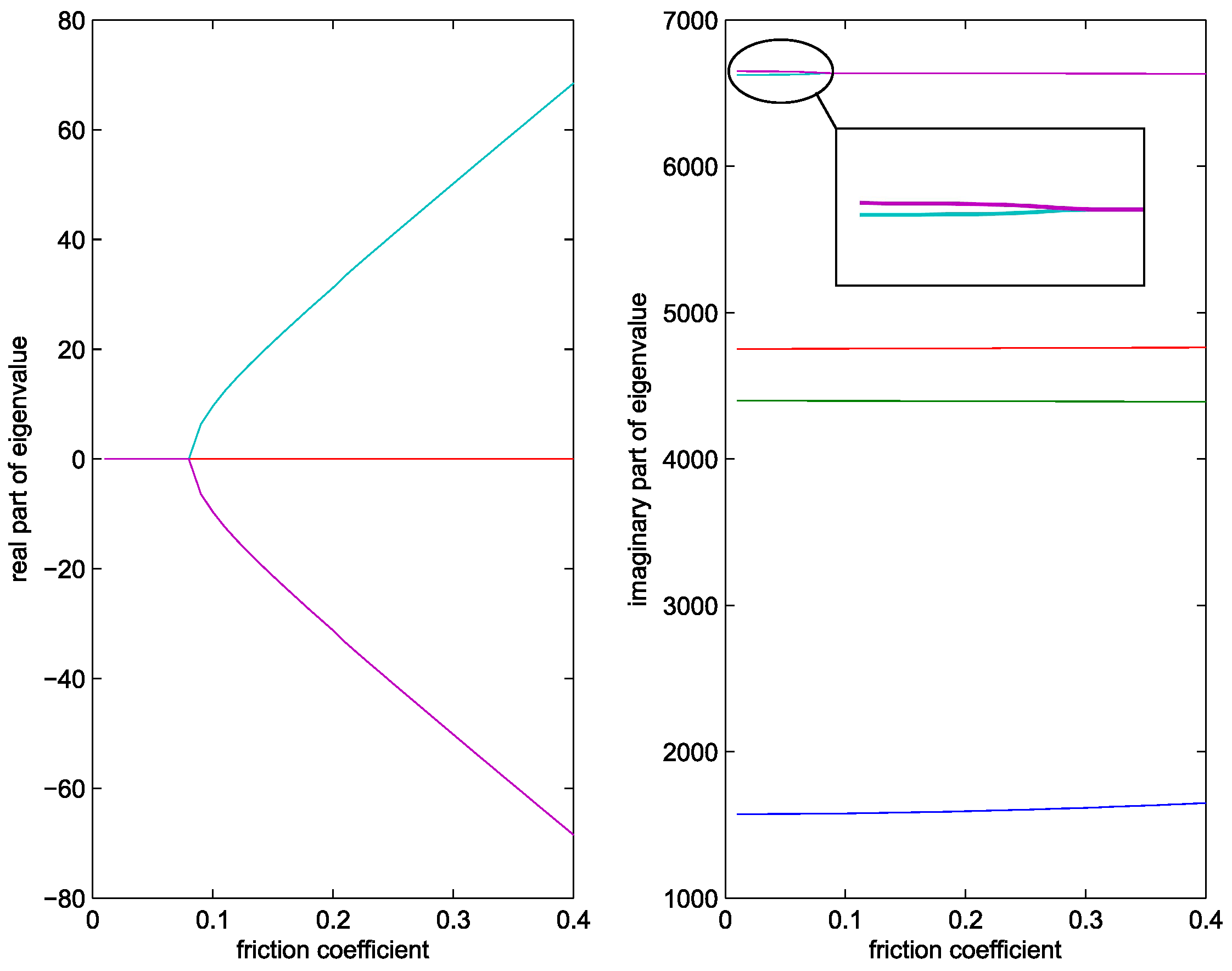
The complex eigenvector has been obtained by using the QRDAMP eigensolver that uses the reduced modal damped matrix to calculate complex damped frequencies damped eigenvalue extraction method. The only parameter forced to vary was the friction coefficient, while the angular velocity value of the track rotating around the vertical axis was considered constant. In Figure 7, the real part and the imaginary part of the eigenvalues of the flexible to rigid system are reported. In particular, only the first five eigenvalues have been reported.
4.2. Transient Analysis
After the modal analysis, we conducted two transient analyses for the finite element system for two friction coefficients. The behavior of the system has been evaluated for values of friction lower and higher than the value for which there is modal coupling, thus resulting in a stable and unstable response of the system, respectively. In Figure 8 is reported the caliper closing motion on the disk. The pads are first placed on the disk in order to guarantee contact , and then, the disk is rotated with a constant angular speed.
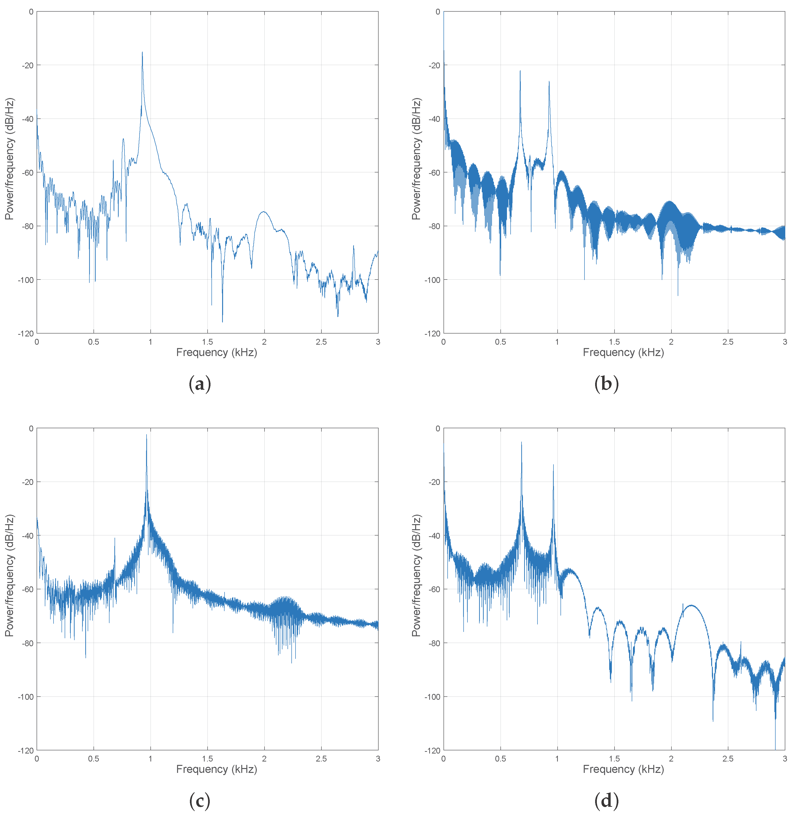
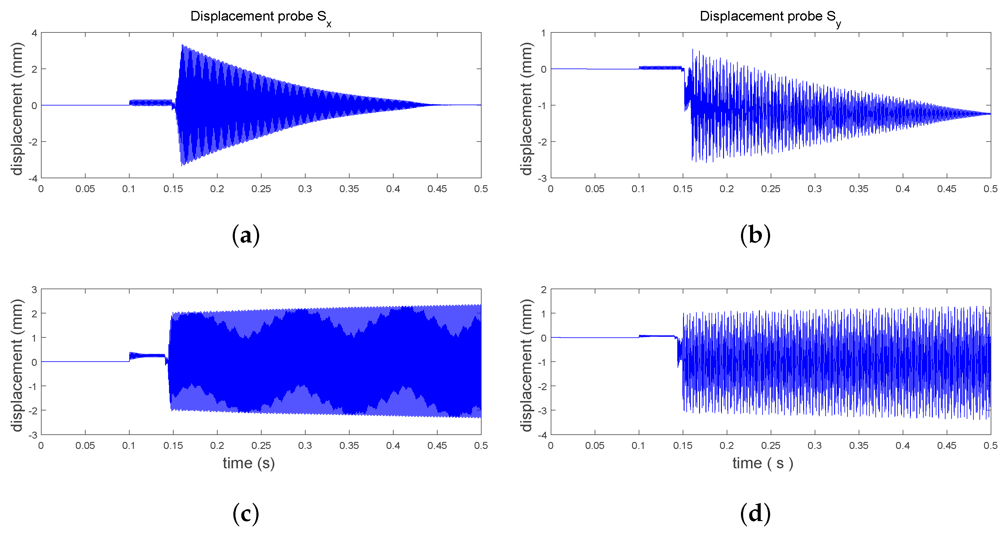
In Figure 9a,b, the horizontal and vertical displacement of the node is reported for the stable case with a friction coefficient lower than the critical value. The vibrations of the node tend to fade after being excited by the rotation of the disc. In Figure 9c,d, instead, for friction higher than the critical value, the system’s response is not mitigated, but tends to amplify over time as reported by the graph. In the graphs, it is possible to notice the clamping of the pads on the disk at 0.1 s and the emergence of stick-slip phenomena with the following rotation of the disk. In Figure 10, instead, is reported the power spectrum of the displacements reported previously of node A, which describes the distribution of power into frequency components composing the vibration recorded, showing the different amplitudes reached by the unstable frequencies. The frequencies found are actually different from those found in the modal analysis conducted on the pad-disk system and reported in Table 2. This difference is due to the non-linear nature of the system due to friction, which emerges in the transient analysis. For this simulation, the system was not pre-stressed.
5. Conclusions
The research of the authors is finalized with the development of new methods for performing accurate analytic modeling [26,27,28,29,30], numerical parameter identification using experimental data [31,32,33,34,35], finite element analysis in the presence of dry friction [36,37,38,39,40,41,42,43,44,45] and control optimization for dynamic models of retrofitted mechanical systems [46,47,48,49,50,51,52,53,54,55,56,57,58,59,60]. The main theories that describe the squeal phenomenon ascribe the increase of vibration amplitudes to the stick-slip mechanism or to the geometrical instability of the brake assembly. Either way, both approaches agree that the squeal phenomenon depends, above all, on the variation of the friction force, which affects the vibration modes of the system. Therefore, in order to reduce or eliminate the squeal phenomenon, it is very important to understand the coupling mechanism so that the key components can be modified accordingly. The aim of this work is to describe the squeal noise mechanism incurred on a disk brake for railway applications studied previously. For this reason, we decided to study the behavior of an ideal mechanical system in the presence of dry friction using a discrete, 1D continuous beam model and a 3D continuous model, both solved by discrete numerical methods. The three cases analyzed in this paper demonstrate how the geometric and friction parameters influence the dynamic behavior of a system. In the discrete case, it is possible to see how the geometry can contrast or support, depending on the needs, the onset of instabilities. On the other hand, the one-dimensional and three-dimensional continuous models show how the coefficient of friction can facilitate the coupling of the vibrational modes of the system, once again leading to forms of instability. The numerical results obtained, despite the simple geometry considered, reproduce the results obtained by analyzing a disk brake used in railway applications well and demonstrate how an appropriate design of the device can counteract the onset of this phenomenon.
Author Contributions
The work has been mainly developed by the first Author (M.C. De Simone). The critical review cared by the second Author (D. Guida) has been greatly appreciated.
Conflicts of Interest
The authors declare no conflict of interest.
References
- Kinkaid, N.M.; O’Reilly, O.M.; Papadopoulos, P. Automotive disc brake squeal. J. Sound Vib. 2008, 267, 105–166. [Google Scholar] [CrossRef]
- Budinsky, T.; Brooks, P.; Barton, D. The influence of disc geometry on the center of pressure and squeal propensity for an automotive disc brake. In Proceedings of the EuroBrake 2017 Conference, Dresden, Germany, 2–4 May 2017. [Google Scholar]
- Sriwiboon, M.; Tiempan, N.; Kaewlob, K.; Rhee, S.K.; Yuhas, D. Disc Pad Physical Properties vs. Porosity: The Question of Compressibility as an Intrinsic Physical Property. SAE Inte. J. Mater. Manuf. 2017, 11. [Google Scholar] [CrossRef]
- Jeong, B.; Kwak, S.D.; Kim, C.K. Optimization for Brake Feeling in Vehicle without Brake Noise; SAE Technical Papers: Warrendale, PA, USA, 2016. [Google Scholar]
- Kanehira, Y.; Aoki, Y.; Nishizawa, Y. Evaluation of an Energy Dissipation Mechanism by Friction for Brake Shims; SAE Technical Papers: Warrendale, PA, USA, 2017. [Google Scholar]
- Festjens, H.; Gaël, C.; Franck, R.; Jean-Luc, D.; Remy, L. Effectiveness of multilayer viscoelastic insulators to prevent occurrences of brake squeal: A numerical study. Appl. Acoust. 2012, 73, 1121–1128. [Google Scholar] [CrossRef]
- Fulco, E.R.; Tonet, G.; Matozo, L.T.; Varante, P.E.D. Influence of the Shim Contact Stiffness on Disc Brakes Squeal Noise; SAE Technical Papers: Warrendale, PA, USA, 2013. [Google Scholar]
- Spelsberg-Korspeter, G. Eigenvalue optimization against brake squeal: Symmetry, mathematical background and experiments. J. Sound Vib. 2012, 331, 4259–4268. [Google Scholar] [CrossRef]
- Lakkam, S.; Koetniyom, S. Optimization of constrained layer damping for strain energy minimization of vibrating pads. Songklanakarin J. Sci. Technol. 2012, 34, 179–187. [Google Scholar]
- Esgandari, M.; Olatunbosun, O. Computer aided engineering prediction of brake noise: Modeling of brake shims. J. Vibr. Control 2016, 22, 2347–2355. [Google Scholar] [CrossRef]
- Zhang, Y.; Li, Z.; Gao, J.; Hong, J.; Villecco, F.; Li, Y. A method for designing assembly tolerance networks of mechanical assemblies. Math. Probl. Eng. 2012. [Google Scholar] [CrossRef]
- Pellegrino, A.; Villecco, F. Design Optimization of a Natural Gas Substation with Intensification of the Energy Cycle. Math. Probl. Eng. 2010. [Google Scholar] [CrossRef]
- Formato, A.; Ianniello, D.; Villecco, F.; Lenza, T.L.L.; Guida, D. Design optimization of the plough working surface by computerized mathematical model. Emir. J. Food Agric. 2017, 29, 36–44. [Google Scholar] [CrossRef]
- Villecco, F.; Pellegrino, A. Entropic measure of epistemic uncertainties in multibody system models by axiomatic design. Entropy 2017, 19, 291. [Google Scholar] [CrossRef]
- Bonnay, K.; Magnier, V.; Brunel, J.F.; Dufrénoy, P.; De Saxcé, G. Influence of geometry imperfections on squeal noise linked to mode lock-in. Inter. J. Sol. Struct. 2015, 75, 99–108. [Google Scholar] [CrossRef]
- Zhang, J.; Li, Y.-H.; Fang, J.; Zhao, W.-Z. Research on squeal noise of tread brake system in rail freight vehicle. IOP Conf. Ser. Mater. Sci. Eng. 2017, 220. [Google Scholar] [CrossRef]
- Zainudin, M.A.; Abu Bakar, A.R. Preventing disc brake squeal using a thin plate shim. Int. J. Veh. Struct. Syst. 2012, 4, 23–27. [Google Scholar]
- Shimizu, H.; Oura, Y.; Suzuki, T.; Sano, Y. The Effect of Grease on Brake Squeal; SAE Technical Papers: Warrendale, PA, USA, 2014. [Google Scholar]
- Wagner, A.; Spelsberg-Korspeter, G.; Hagedorn, P. Structural optimization of an asymmetric automotive brake disc with cooling channels to avoid squeal. J. Sound Vib. 2014, 333, 1888–1898. [Google Scholar] [CrossRef]
- Lv, H.-M.; Zhang, L.-J.; Yu, Z.-P. Influence of surface run-out on disc brake squeal. J. Vibroeng. 2013, 15, 520–531. [Google Scholar]
- Sriwiboon, L.; Wu, J.; Meng, D. Transient Analysis of a Flexible Pin-on-Disk System and Its Application to the Research into Time-Varying Squeal. J. Vib. Acoust. Trans. ASME 2018, 140. [Google Scholar] [CrossRef]
- Charroyer, L.; Chiello, O.; Sinou, J.-J. Parametric study of the mode coupling instability for a simple system with planar or rectilinear friction. J. Sound Vib. 2016, 384, 94–112. [Google Scholar] [CrossRef]
- Du, Y.; Wang, Y. Squeal analysis of a modal-parameter-based rotating disc brake model. Int. J. Mech. Sci. 2017, 131–132, 1049–1060. [Google Scholar] [CrossRef]
- Jaeyoung, K. Automotive brake squeal analysis with rotating finite elements of asymmetric disc in time. J. Sound Vib. 2017, 393, 388–400. [Google Scholar]
- De Simone, M.C.; Rivera, Z.B.; Guida, D. Finite Element Analysis on Squeal-Noise in Railway Applications. FME Trans. 2018, 46, 93–100. [Google Scholar]
- Pappalardo, C.M. A Natural Absolute Coordinate Formulation for the Kinematic and Dynamic Analysis of Rigid Multibody Systems. Nonlinear Dyn. 2015, 81, 1841–1869. [Google Scholar] [CrossRef]
- Kulkarni, S.; Pappalardo, C.M.; Shabana, A.A. Pantograph/Catenary Contact Formulations. ASME J. Vib. Acoust. 2017, 139, 1–12. [Google Scholar] [CrossRef]
- Guida, D.; Pappalardo, C.M. On the use of Two-dimensional Euler Parameters for the Dynamic Simulation of Planar Rigid Multibody Systems. Arch. Appl. Mech. 2017, 1–19. [Google Scholar] [CrossRef]
- Guida, D.; Pappalardo, C.M. Forward and Inverse Dynamics of Nonholonomic Mechanical Systems. Meccanica 2014, 49, 1547–1559. [Google Scholar] [CrossRef]
- Guida, D.; Nilvetti, F.; Pappalardo, C.M. Mass, Stiffness and Damping Identification of a Two-story Building Model. In Proceedings of the 3rd ECCOMAS Thematic Conference on Computational Methods in Structural Dynamics and Earthquake Engineering (COMPDYN 2011), Corfu, Greece, 25–28 May 2011; pp. 25–28. [Google Scholar]
- Pappalardo, C.M.; Guida, D. Experimental Identification and Control of a Frame Structure using an Actively Controlled Inertial-based Vibration Absorber. In Proceedings of the International Conference on Control, Artificial Intelligence, Robotics and Optimization (ICCAIRO 2017), Prague, Czech Republic, 20–22 May 2017; pp. 99–104. [Google Scholar]
- Guida, D.; Nilvetti, F.; Pappalardo, C.M. On Parameter Identification of Linear Mechanical Systems. In Proceedings of the 3rd International Conference on Applied Mathematics, Simulation, Modelling, Circuits, Systems and Signals, (WSEAS), Vouliagmeni Beach, Athens, Greece, 29–31 December 2009; pp. 55–60. [Google Scholar]
- Guida, D.; Nilvetti, F.; Pappalardo, C.M. Parameter Identification of a Two Degrees of Freedom Mechanical System. Int. J. Mech. 2009, 3, 23–30. [Google Scholar]
- Guida, D.; Pappalardo, C.M. Sommerfeld and Mass Parameter Identification of Lubricated Journal Bearing. WSEAS Trans. Appl. Theor. Mech. 2009, 4, 205–214. [Google Scholar]
- Guida, D.; Nilvetti, F.; Pappalardo, C.M. Experimental Investigation on a New Hybrid Mass Damper. In Proceedings of the 8th International Conference on Structural Dynamics (EURODYN 2011), Leuven, Belgium, 4–6 July 2011; pp. 1644–1649. [Google Scholar]
- De Simone, M.C.; Guida, D. Dry Friction Influence on Structure Dynamics. In Proceedings of the 5th ECCOMAS Thematic Conference on Computational Methods in Structural Dynamics and Earthquake Engineering (COMPDYN 2015), Crete Island, Greece, 25–27 May 2015; pp. 4483–4491. [Google Scholar]
- Guida, D.; Nilvetti, F.; Pappalardo, C.M. Instability Induced by Dry Friction. Int. J. Mech. 2009, 3, 44–51. [Google Scholar]
- Guida, D.; Nilvetti, F.; Pappalardo, C.M. Dry Friction Influence on Cart Pendulum Dynamics. Int. J. Mech. 2009, 3, 31–38. [Google Scholar]
- Guida, D.; Nilvetti, F.; Pappalardo, C.M. Dry Friction Influence on Inverted Pendulum Control. In Proceedings of the 3rd International Conference on Applied Mathematics, Simulation, Modelling (ASM’09), Vouliagmeni Beach, Athens, Greece, 29–31 December 2009; pp. 49–54. [Google Scholar]
- Guida, D.; Nilvetti, F.; Pappalardo, C.M. Friction Induced Vibrations of a Two Degrees of Freedom System. In Proceedings of the 10th WSEAS International Conference on Robotics, Control and Manufacturing Technology (ROCOM ’10), Hangzhou, China, 11–13 April 2010; pp. 133–136. [Google Scholar]
- Ruggiero, A.; Affatato, S.; Merola, M.; De Simone, M.C. FEM analysis of metal on UHMWPE total hip prosthesis during normal walking cycle. In Proceedings of the XXIII Conference of the Italian Association of Theoretical and Applied Mechanics (AIMETA 2017), Salerno, Italy, 4–7 September 2017. [Google Scholar]
- Pappalardo, C.M.; Yu, Z.; Zhang, X.; Shabana, A.A. Rational ANCF Thin Plate Finite Element. ASME J. Comput. Nonlinear Dyn. 2016, 11, 1–15. [Google Scholar] [CrossRef]
- Pappalardo, C.M.; Wallin, M.; Shabana, A.A. A New ANCF/CRBF Fully Parametrized Plate Finite Element. ASME J. Comput. Nonlinear Dyn. 2017, 12, 1–13. [Google Scholar]
- Pappalardo, C.M.; Wang, T.; Shabana, A.A. Development of ANCF Tetrahedral Finite Elements for the Nonlinear Dynamics of Flexible Structures. Nonlinear Dyn. 2017, 89, 2905–2932. [Google Scholar] [CrossRef]
- Pappalardo, C.M.; Wang, T.; Shabana, A.A. On the Formulation of the Planar ANCF Triangular Finite Elements. Nonlinear Dyn. 2017, 89, 1019–1045. [Google Scholar] [CrossRef]
- De Simone, M.C.; Russo, S.; Rivera, Z.B.; Guida, D. Multibody Model of a UAV in Presence of Wind Fields. In Proceedings of the 2017 International Conference on Control, Artificial Intelligence, Robotics & Optimization (ICCAIRO), Prague, Czech Republic, 20–22 May 2017; pp. 83–88. [Google Scholar]
- De Simone, M.C.; Guida, D. Identification and Control of a Unmanned Ground Vehicle by Using Arduino. UPB Sci. Bull. Ser. D 2018. accepted. [Google Scholar]
- Concilio, A.; De Simone, M.C.; Rivera, Z.B.; Guida, D. A New Semi-Active Suspension System for Racing Vehicles. FME Transactions. 2017, 45, 565–571. [Google Scholar] [CrossRef]
- Sharifzadeh, M.; Timpone, F.; Farnam, A.; Senatore, A.; Akbari, A. Tyre-Road Adherence Conditions Estimation for Intelligent Vehicle Safety Applications. In Advances in Italian Mechanism Science; Springer: New York, NY, USA, 2017; pp. 389–398. [Google Scholar]
- Guida, D.; Nilvetti, F.; Pappalardo, C.M. Optimal Control Design by Adjoint-Based Optimization for Active Mass Damper with Dry Friction. In Proceedings of the 4th International Conference on Computational Methods in Structural Dynamics and Earthquake Engineering COMPDYN 2013, Kos Island, Greece, 12–14 June 2013; pp. 1–19. [Google Scholar]
- Pappalardo, C.M.; Patel, M.D.; Tinsley, B.; Shabana, A.A. Contact Force Control in Multibody Pantograph/ Catenary Systems. Proc. Inst. Mech. Eng. Part K J. Multibody Dyn. 2016, 230, 307–328. [Google Scholar] [CrossRef]
- Pappalardo, C.M.; Patel, M.D.; Tinsley, B.; Shabana, A.A. Pantograph/Catenary Contact Force Control. In Proceedings of the ASME 2015 International Design Engineering Technical Conferences and Computers and Information in Engineering Conference IDETC/CIE 2015, Boston, MA, USA, 2–5 August 2015. [Google Scholar]
- Pappalardo, C.M.; Guida, D. Adjoint-based Optimization Procedure for Active Vibration Control of Nonlinear Mechanical Systems. ASME J. Dyn. Syst. Meas. Control 2017, 139, 1–11. [Google Scholar] [CrossRef]
- Pappalardo, C.M.; Guida, D. Control of Nonlinear Vibrations using the Adjoint Method. Meccanica 2017, 52, 2503–2526. [Google Scholar] [CrossRef]
- Quatrano, A.; De Simone, M.C.; Rivera, Z.B.; Guida, D. Development and Implementation of a Control System for a retrofitted CNC Machine by using Arduino. FME Trans. 2017, 45, 578–584. [Google Scholar] [CrossRef]
- Guida, D.; Pappalardo, C.M. Control Design of an Active Suspension System for a Quarter-Car Model with Hysteresis. J. Vib. Eng. Technol. 2015, 3, 277–299. [Google Scholar]
- Guida, D.; Pappalardo, C.M. A New Control Algorithm for Active Suspension Systems Featuring Hysteresis. FME Trans. 2013, 41, 285–290. [Google Scholar]
- Guida, D.; Nilvetti, F.; Pappalardo, C.M. Adjoint-based Optimal Control Design for a Cart Pendulum System with Dry Friction. In Proceedings of the ECCOMAS Thematic Conference on Multibody Dynamics, Zagreb, Croatia, 1–4 July 2013; pp. 269–285. [Google Scholar]
- De Simone, M.C.; Guida, D. On the Development of a Low Cost Device for Retrofitting Tracked Vehicles for Autonomous Navigation. In Proceedings of the XXIII Conference of the Italian Association of Theoretical and Applied Mechanics (AIMETA 2017), Salerno, Italy, 4–7 September 2017. [Google Scholar]
- Ruggiero, A.; De Simone, M.C.; Russo, D.; Guida, D. Sound pressure measurement of orchestral instruments in the concert hall of a public school. Int. J. Circuits Syst. Signal Process. 2016, 10, 75–812. [Google Scholar]
Figure 1.
Discrete mechanical model.

Figure 2.
Eigenvalues of stiffness matrix for and . (a) Real part of the eigenvalues; (b) imaginary part of the eigenvalues.
Figure 2.
Eigenvalues of stiffness matrix for and . (a) Real part of the eigenvalues; (b) imaginary part of the eigenvalues.
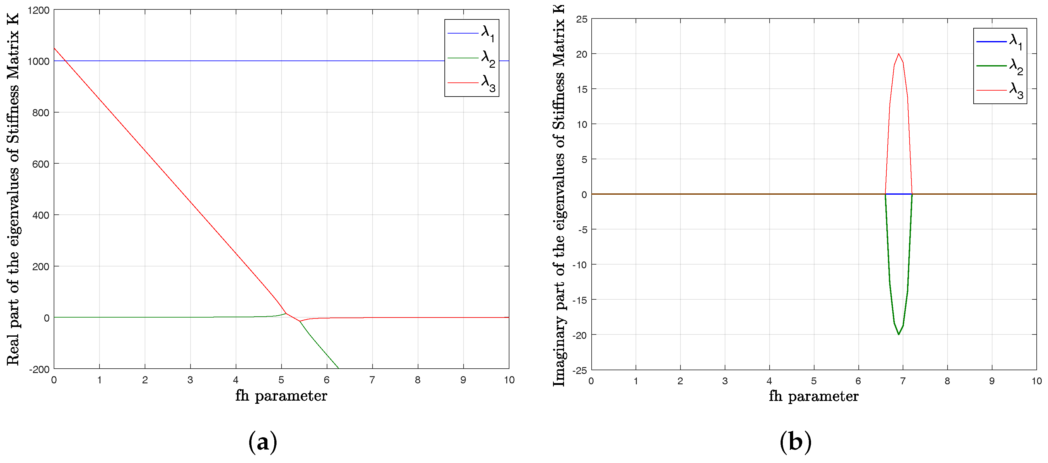
Figure 3.
Properties for the continuous model.
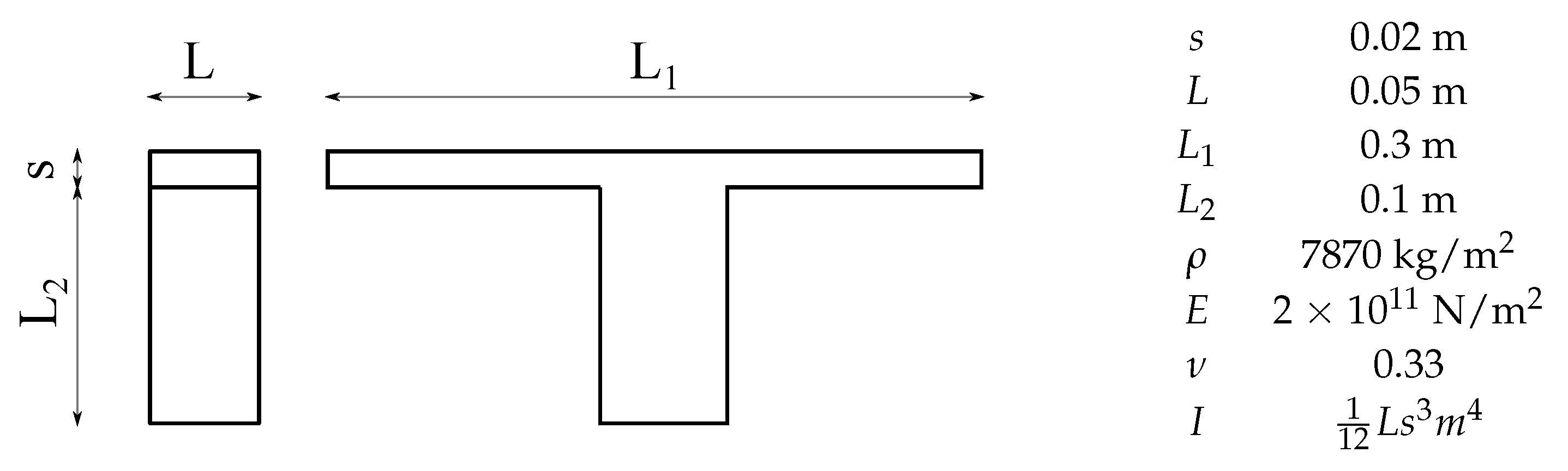
Figure 4.
Longitudinal motion eigenvalues. (a) Real part of the eigenvalues; (b) imaginary part of the eigenvalues.
Figure 4.
Longitudinal motion eigenvalues. (a) Real part of the eigenvalues; (b) imaginary part of the eigenvalues.
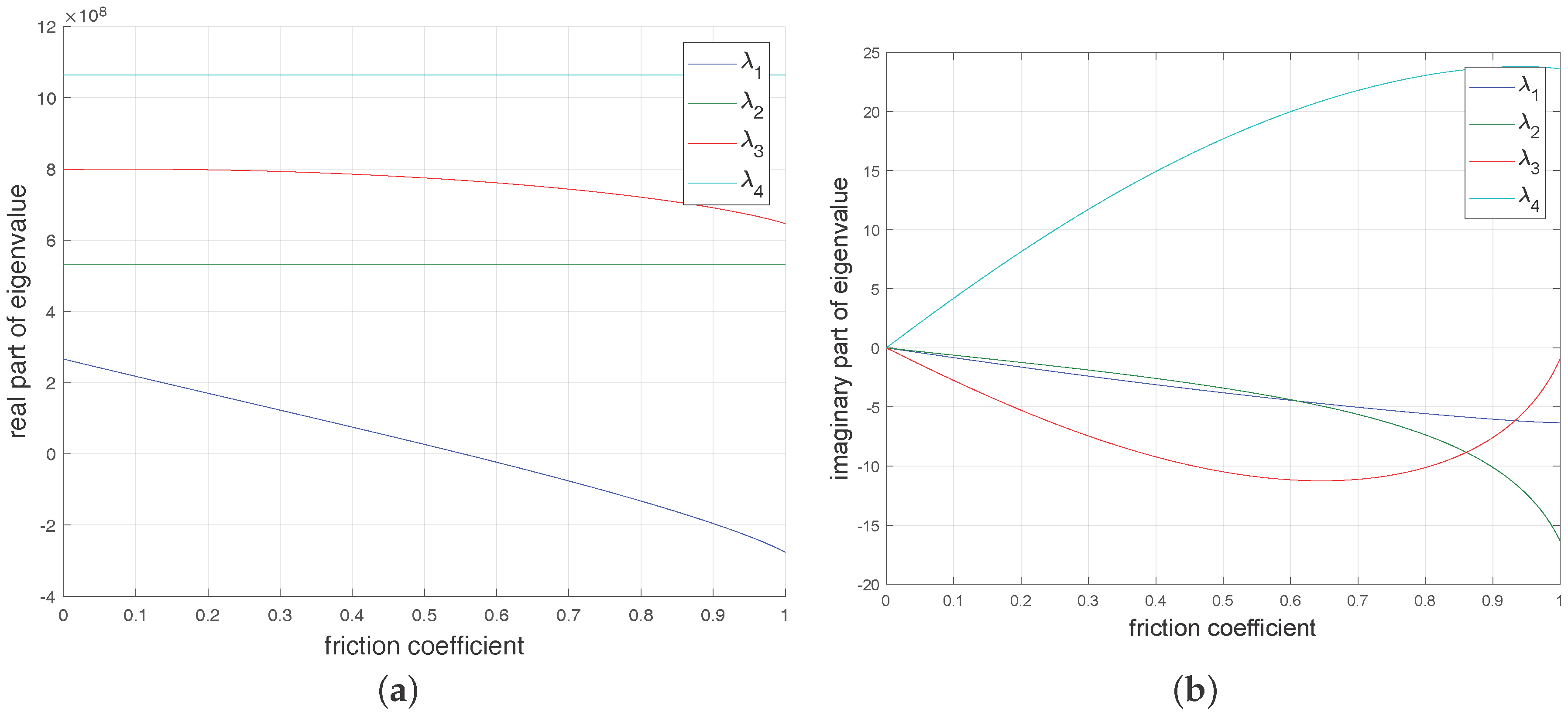
Figure 5.
Transversal motion eigenvalues. (a) Real part of the eigenvalues; (b) imaginary part of the eigenvalues.
Figure 5.
Transversal motion eigenvalues. (a) Real part of the eigenvalues; (b) imaginary part of the eigenvalues.

Figure 6.
Meshed system.

Figure 7.
Complex eigenvalues of the pin-track system under dry friction.

Figure 8.
Caliper closing motion.
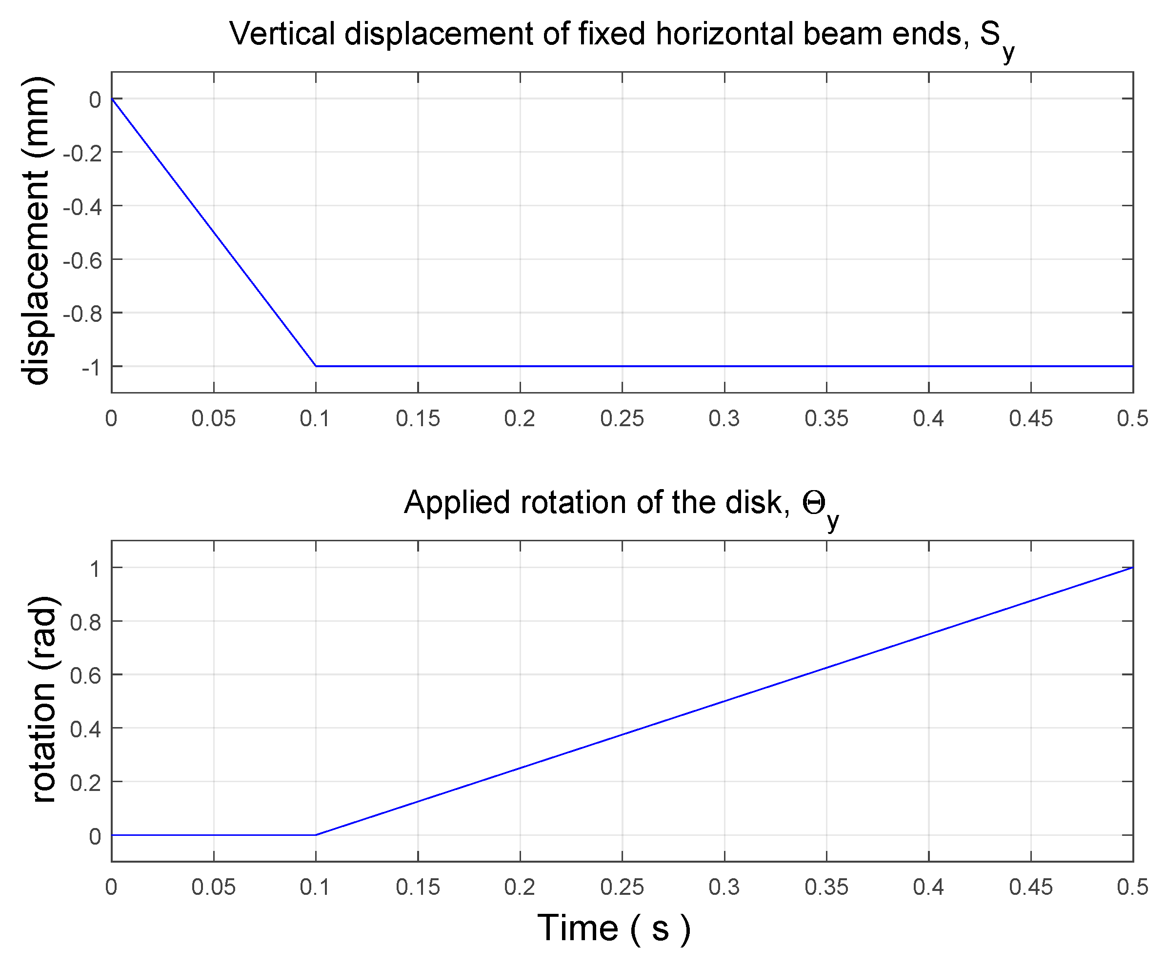
Figure 9.
Displacement time history of node A. (a) Stable case; (b) stable case; (c) unstable case; (d) unstable case.
Figure 9.
Displacement time history of node A. (a) Stable case; (b) stable case; (c) unstable case; (d) unstable case.

Figure 10.
Power spectral density estimate of the displacement of node A. (a) Stable case; (b) stable case; (c) unstable case; (d) unstable case.
Figure 10.
Power spectral density estimate of the displacement of node A. (a) Stable case; (b) stable case; (c) unstable case; (d) unstable case.

Table 1.
Values of the parameter for several combinations and parameters.
| = 0.01 | −5.3 | −6.9 | −10.3 | −20.9 | 505.2 |
| = 1 | −10.2 | −20.2 | ⋯ | 20.3 | 10.2 |
| = 100 | −505.2 | 20.9 | 10.3 | 6.9 | 5.3 |
Table 2.
First 10 modes for the two cases of study reported.
| Stable Case () | Unstable Case () | |||
|---|---|---|---|---|
| Mode | Frequency (Hz) | Stability | Frequency (Hz) | Stability |
| 1 | 1080.4 | 0 | 1080.4 | 0 |
| 2 | 1572 | 0 | 1574.8 | 0 |
| 3 | 2729.5 | 0 | 2729.7 | 0 |
| 4 | 4390,7 | 0 | 4389.8 | 0 |
| 5 | 4582.7 | 0 | 4582.6 | 0 |
| 6 | 4745.9 | 0 | 4747.2 | 0 |
| 7 | 6618.8 | 0 | 6624.9 | 12.684 |
| 8 | 6631.9 | 0 | 6624.9 | −12.684 |
| 9 | 7536.5 | 0 | 7536.5 | 0 |
| 10 | 7943.2 | 0 | 7943.1 | 0 |
© 2018 by the authors. Licensee MDPI, Basel, Switzerland. This article is an open access article distributed under the terms and conditions of the Creative Commons Attribution (CC BY) license (http://creativecommons.org/licenses/by/4.0/).
Share and Cite
MDPI and ACS Style
De Simone, M.C.; Guida, D. Modal Coupling in Presence of Dry Friction. Machines 2018, 6, 8. https://doi.org/10.3390/machines6010008
AMA Style
De Simone MC, Guida D. Modal Coupling in Presence of Dry Friction. Machines. 2018; 6(1):8. https://doi.org/10.3390/machines6010008
Chicago/Turabian StyleDe Simone, Marco Claudio, and Domenico Guida. 2018. "Modal Coupling in Presence of Dry Friction" Machines 6, no. 1: 8. https://doi.org/10.3390/machines6010008
Note that from the first issue of 2016, this journal uses article numbers instead of page numbers. See further details here.