1. Introduction
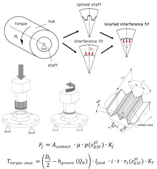
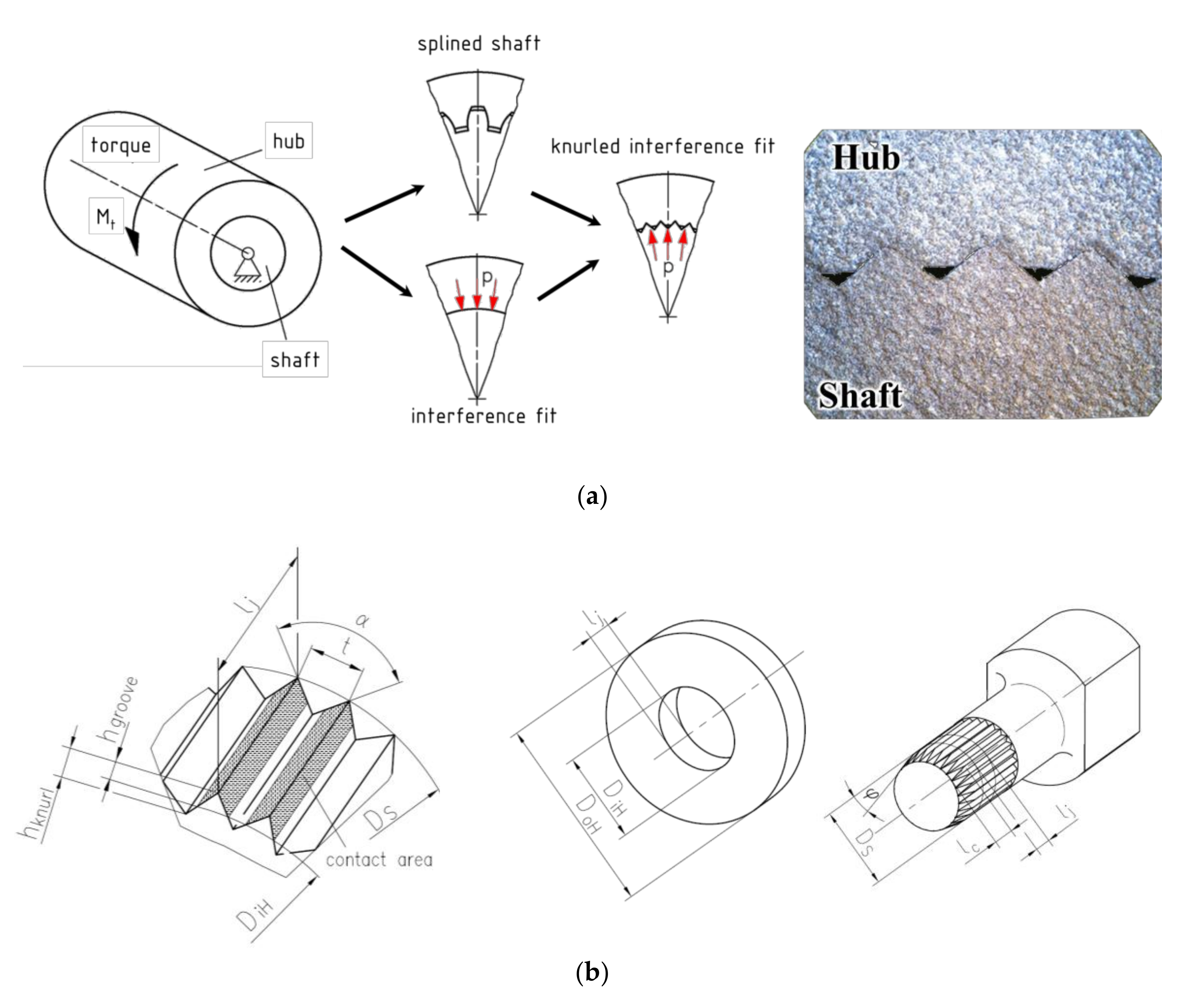
Turning drives are commonly used and important actuators in machines. Several principles for transmitting rotatory drive torque through machine parts from the source of power to the output side are established. Well-known principles are the key fit joint or the splined shaft fit, which belong to the group of so-called “positive fits” or “form fits”. By contrast, the interference fit (“non-positive fit” or “friction fit”), where an oversized cylindrical shaft is pressed into the undersized cylindrical hub, transmits torque by joint pressure and is used in numerous applications, such as train axles. Combining these two well-known joining methods enables assembly of a splined shaft and hub with a cylindrical hole by axial plastic forming, bringing together the advantages of both principles and increasing the maximal transmissible torque (
Figure 1). This so-called knurled interference fit (KIF) is fabricated by axial pressing the knurled shaft into a slightly undersized hole in the softer hub. The plastic forming of the counter profile in the hub eliminates tolerance errors and guarantees a homogenous force distribution over all tappets during operation. Furthermore, axial loads can be transmitted by the groove pressure in the connection.
The joining process of well-known interference push-in-connection can be estimated both according to the German standard for calculating interference fit DIN 7190 [
1] as well as numerical methods from several investigations (e.g., [
2,
3]). In contrast to this investigation dealing global elastic-plastic relations with low deformation degree, a KIF connection is formed mainly locally at the contact groove with very high local deformation. Therefore the joining process of KIF cannot be reproduced with the presented methods.
In contrast to the conventional interference fit, the groove pressure decreasing separation frequency [
4] in high-speed applications does not lead to transmission break down due to the form fit of the tappets. The knurl profile is understood according to German standard DIN 82 [
5].
Equations describing this joint were recently published. Extensive recent overviews of past research can be found in [
6,
7,
8], where the joining process and torsional load capacity are investigated. Nonetheless, the state of the knowledge is not sufficient for design of a universal KIF for a broad range of applications. Additionally, the valid patents in Europe lack detailed instructions for design and scientific explanations.
Lätzer [
6] recently described the influence of different geometric parameters on joining and operating behavior, including important consequences of joining by cutting and forming. Fits joined by forming with shaft chamfer angles (SCA)
ϕ < 60° are able to transmit 40% more torque than fits joined by cutting, where
ϕ = 90°. Additionally, an analytical approach for designing KIF based on operational state is introduced. Equations (1) and (2) shows Lätzer’s approach [
6] for estimation of necessary joining force and maximal transmittable torque:
With the exception of the hub-diameter-ratio (HDR), this formulation includes the geometry parameters of KIF (
Figure 1). The terms
and
, the equivalent plastic strain and the strain hardening, can be calculated by the Ludwik approach. Additionally, differentiation between the cutting and forming joining methods is performed. The results of this study are valid only for thick walled hubs of ductile aluminum material. The value of the hub-diameter ratio is the thickness rate of the hub and can be calculated for steady hub outer diameters using Equation (3):
The interference
Igeo is the difference between the shaft diameter
DS and the hub diameter
DiH:
Bader investigated the self-cutting knurling shaft-hub-connection [
9] and determined the necessary hardness-ratio of the hub and shaft, which is calculated from different combinations of steel, brass, and aluminum. The minimal hardness ratio was 1.8. Furthermore, the first applicable empirical approaches were derived, but they lacked the universal validity for forming KIF.
Against this background, the central question that motivates the present research is the influence of other parameters on the maximal transmittable torque of the knurled interference fit, such as the hub thickness in combination with the shaft chamfer angle.
Further studies investigate forming KIF connections with different, and not standardized, geometries and tappet orientations [
8]. Similar increasing load capacity tendencies were recorded in dependence of growing interference. Due to high influence of the different tappet geometry on the plastic forming during joining process, the quantitative comparability is not possible. Additionally, the shape development of the tappets is not introduced.
The lack of complete investigations on the influence of hub outside-diameter on joining and torsional load force make this research necessary. The loss of stiffness of thin walled hubs will change the maximal possible load capacity of the KIF. The validity condition of this statement is the failure of the knurls.
First, experiments investigating joining and operating state are performed. The present analytical approaches will then be extended.
Table 1 shows the parameters that influence joining forces and maximal transmittable torsional load in the design of a KIF. The most important factors are the shaft diameter, the joining length, and the geometric interference (
Figure 1).
2. Materials and Methods
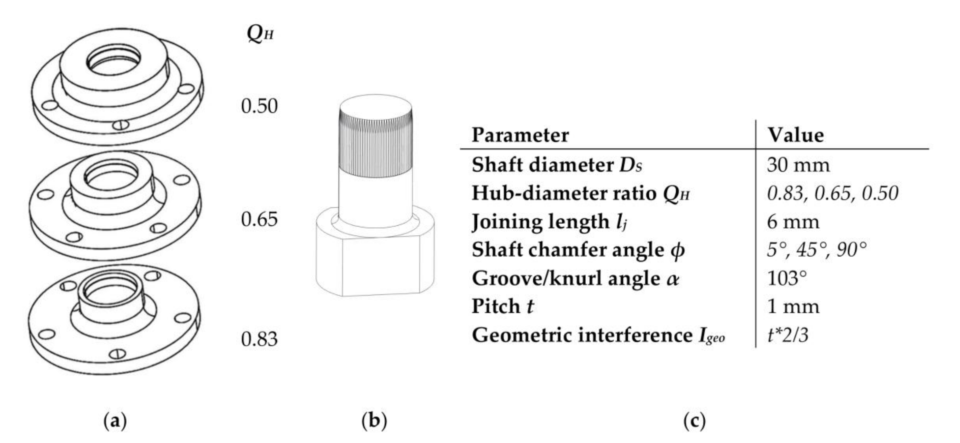
Investigations on hub outside-diameter are performed on specimens with flange geometries as shown in
Figure 2. The figured hub specimens are manufactured from rods of AlMgSi1, EN AW-6082, with heat treatment T6. The shaft material is bearing steel 100Cr6. The basic shaft geometry is manufactured in the untreated state. Subsequently, the knurling is fabricated on the specimen by recursive axial forming. Finally, the specimen is hardened to a hardness of approximately 758 HV. The resulting hardness ratio of joined specimens is 1:7 (
Table 2).
Figure 2 shows the specimen geometry as well as the chosen parameter values for the present study. The influence of different hub-diameter-ratios
QH on joining forces and maximal torque capacity differed by cutting and forming joining method is examined by varying the shaft chamfer angle
ϕ for each HDR.
The joining process is performed in a special guiding appliance that guarantees the coaxial position of hub and shaft during the assembly in hydraulic press. The joining velocity vj was 0.5 mm/s due to comparability within the presented literature. The surfaces were cleaned before a dry joining process. The maximal joining force is derived from the gained force-stroke-signal.
After a one-day rest period the assembled connection is tested in a hydraulic torsional test bench, where the torque progression over the torque angle is measured until the failure of KIF occurs (stress-controlled test). At this value, the maximal torque capacity is obtained.
Material properties (
Table 2) were estimated in tensile testing according to ISO 6892 [
10] for the hub material AlMgSi1. In the case of the hardened steel shaft the hardness was measured according to ISO 6507 [
11] and the tensile strength was calculated according to [
6]. All tests were performed at room temperature.
3. Results
3.1. Experimental Results
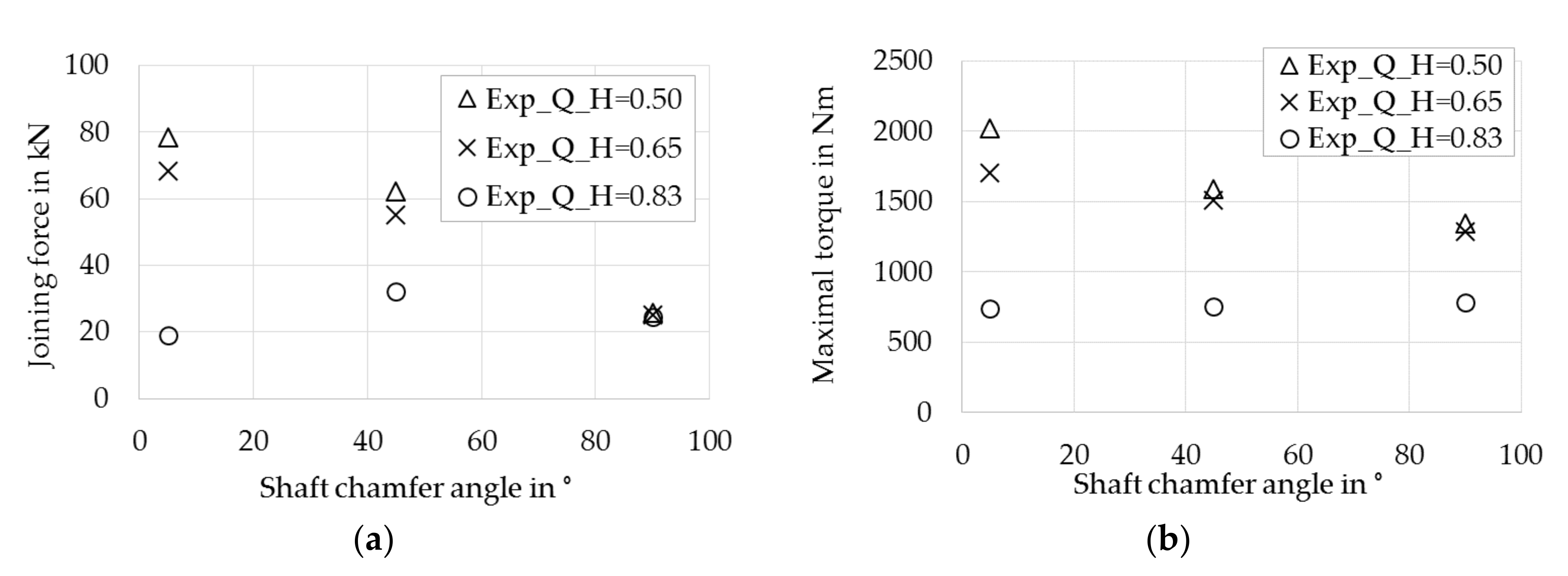
Joining force plots shown in
Figure 3a summarize the maximal forces of tested specimens. Every point represents a mean value of two repetitions with a maximal standard deviation of maximally 3.4% (joining force) and 2.9% (torque), respectively. At the lower HDRs of
QH = 0.65 and
QH = 0.5, the maximum joining force increases with decreasing SCA, peaking at
α = 5°. 12% lower values for
QH = 0.65 are observed at this point.
In contrast, the thin walled hub with QH = 0.83 shows a plateau at lower joining forces. While all HDR forces are the same at α = 90°, values diverge nonlinearly with decreasing SCA.
The forming process causes redirection of the axial force to a hub-expending radial force, which results in higher groove pressure and higher joining forces than the cutting process for hubs with higher wall thicknesses. In contrast, the thin walled hub does not show this effect due to high hub expansion during joining and the related lower plastic deformation and shorter height of teeth in the hub. The joining forces of forming KIF are about 20% lower than for cutting KIF.
Figure 3b shows the corresponding maximal torsional load, which is the load where the KIF fails. Similar trends of joining force (
Figure 3a) can be observed. Except for the thin-walled hub, where the values at the plateau are lower, the forming connection also achieves a higher maximal torque. The higher torque capacity of forming KIF is rationalized by strain hardening of the ductile material AlMgSi1.
Additionally, the maximal torsional load of a thin walled KIF QH = 0.83 joined by cutting (α = 90°) is about 40% lower than KIF with QH = 0.5 and QH = 0.65. This difference can be explained by radial expansion of the hub caused by the torque applied during testing. Enlargement of the hub inner diameter, caused by the force split of the torque on the sloping side of the formed/cut knurling, leads to decreased contact area. Interrelated reduction of the teeth shear area results in a smaller torque capacity for the hub with thin walls with QH = 0.83.
3.2. Analytical Approach for Calculation of Joining Force and Torque Capacity
The following description involves including the tested parameter in the available calculation method, thereby expanding the approach of Lätzer.
The first set of analysis highlights the impact of HDR on the formation of the counter profile in the hub.
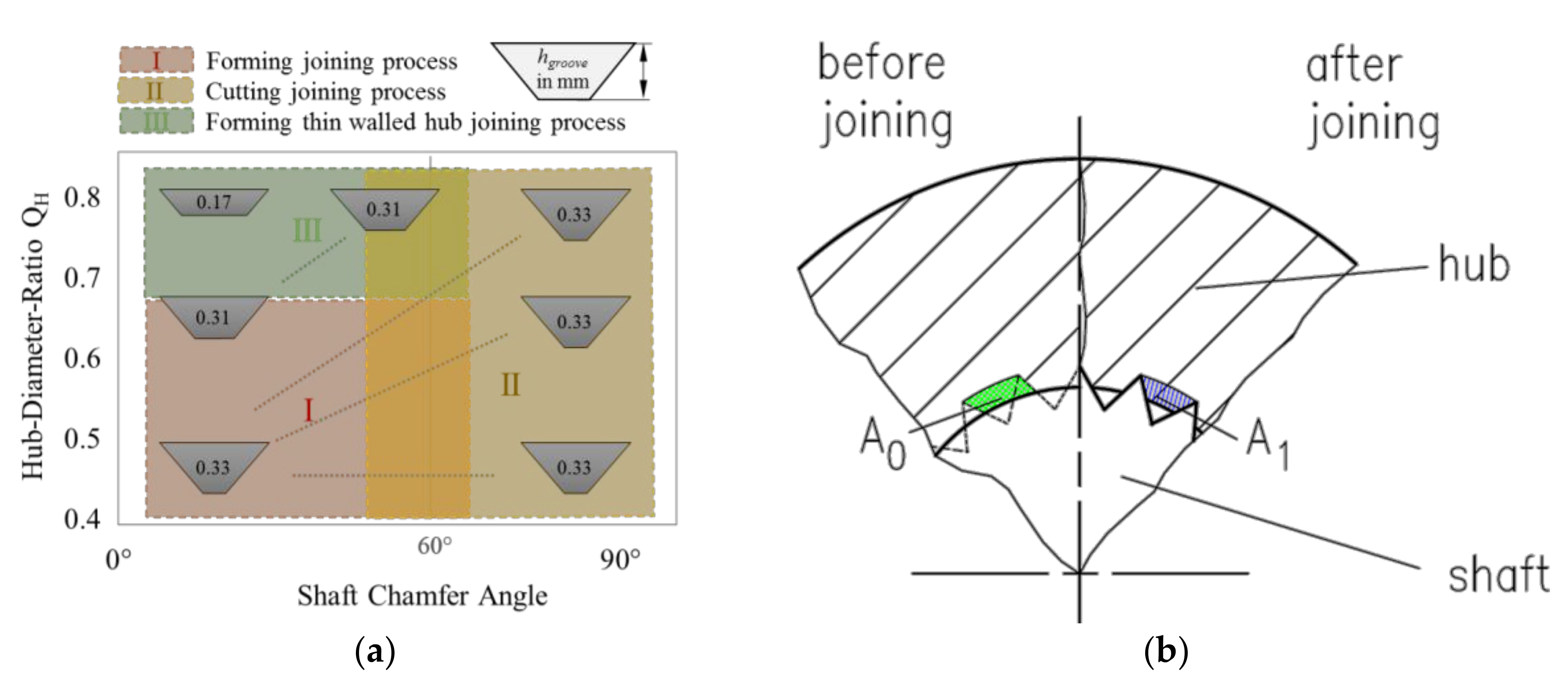
Figure 4 shows the different groove heights
hgroove dependency on SCA and HDR. The green area represents the neglected area in the field of thin hub and forming joining process. At this point, the contact area is reduced as a result of radial hub expansion.
When low radial forces are initiated in the cutting process, groove formation is due to material removal resulting in equal groove heights (
Figure 4a, yellow area).
Knurl forming on the thick hub, which is at lower HDR, leads to constant groove heights. In contrast to the cutting process, the material undergoes strain hardening, which is calculated in Equations (5) and (6) in the equivalent plastic strain term .
The intersection of the described areas border the crossing parameter area, where the joining processes are mixed.
In addition to Lätzer’s approach, the following equations are used for calculation of joining force
and maximum torque
considering the tested parameters:
Here the coefficient of friction
is determined by a standardized tube friction method from [
12]. The groove pressure
is calculated according to [
6] to be equal to the flow stress
.
The modification to the original Lätzer approach [
6] consists of new reference areas
and
for calculation of equivalent plastic strain
, which is defined as:
The adjusted calculation of the areas
and
(
Figure 4b) leads to a more accurate equivalent plastic strain which allows the numerical modelling of flow stress with the Ludwik approach [
13]. With varying hub thickness, counter profile geometry also has to be considered. According to Figure 4, the required hub groove height
can be established by:
The height of the knurl
results from the groove angle and the pitch:
Furthermore, the contact area
which influences the contact normal force is calculated by:
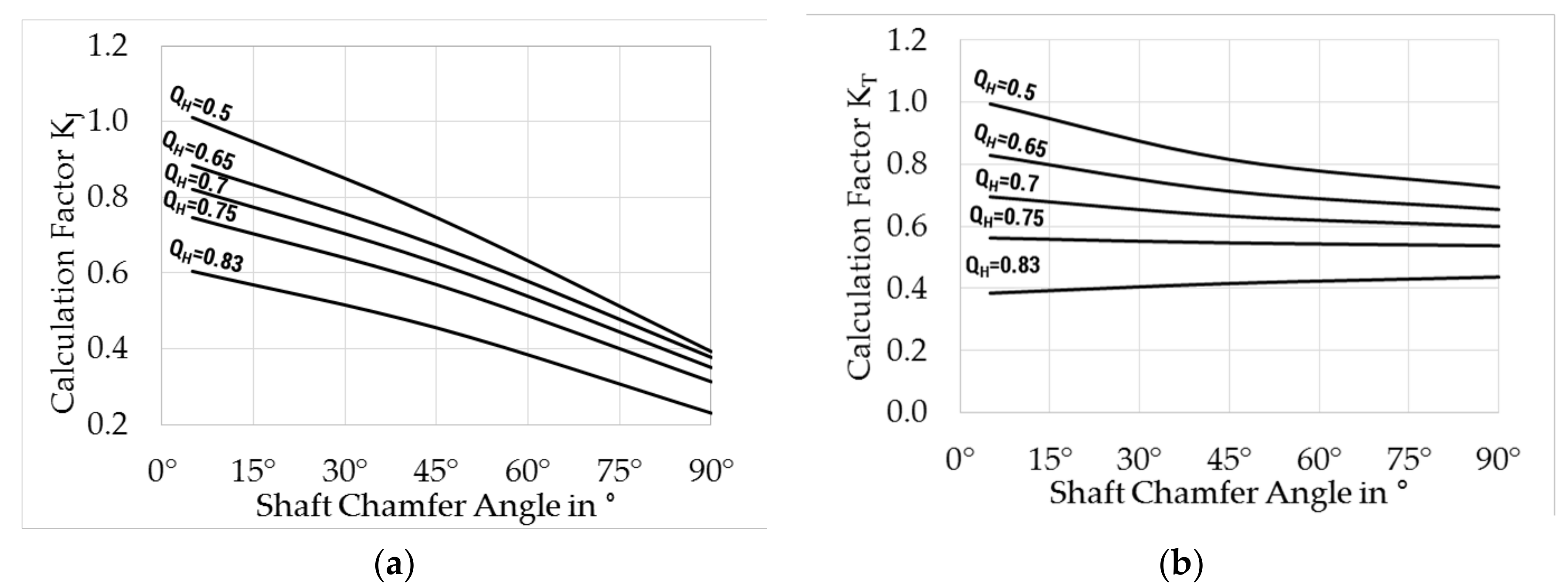
The influence of HDR and SCA is accounted for with the empirical-analytical functions
and
, which include expansion of the hub and differentiate between the cutting and forming processes:
Figure 5 shows the cross-section curves for several HDR depending on SCA according to Equations (13) and (14). Corresponding to the experimental results, a decrease of load can be registered with decreasing SCA (cutting process) and increasing HDR (thin-walled hub).
4. Discussion
As stated in the Introduction, the goal of the present research was to bridge knowledge gaps in the parameter range of the knurled interference fit. Joining force, as well as torsional load tests, were performed with varying hub-diameter ratios with the cutting and forming joining processes of shafts and hubs.
To conclude the experimental results, the present study supports previous research in this area. A similar influence of shaft chamfer angle was determined as found in [
7,
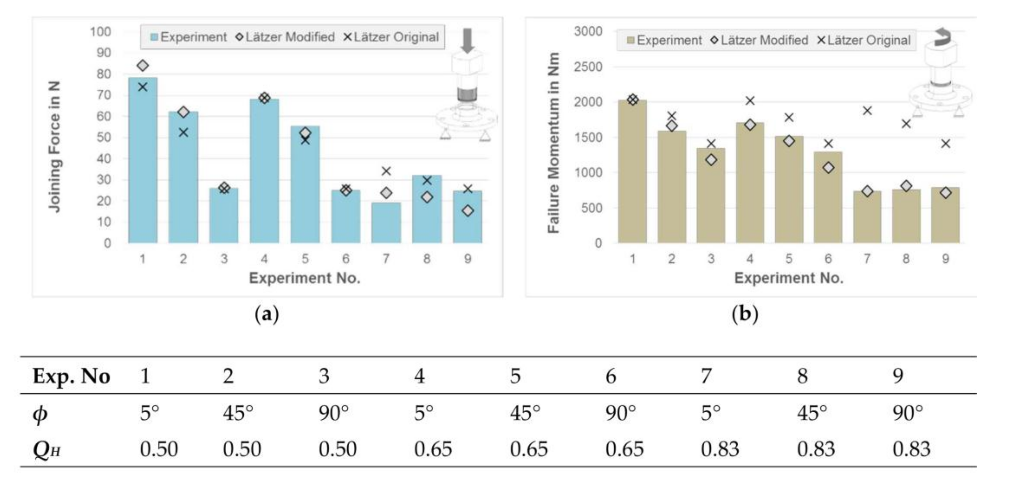
8]. As expected, including the new parameters in the known analytical approaches led to calculation errors, which overestimated the load capacity of KIF at higher HDR. Therefore, modifications of Lätzer’s approach were made with the goal of minimizing calculation error. Considering the described points,
Figure 6 shows a comparison of experimental results between “Lätzer-original” und “Lätzer-modified”. Both show a low the deviation of calculated joining force of maximal 7% in case of forming joining (experiments no. 1–6,
Figure 6a). For cutting connections
deviations up to 38% of Lätzer-original” and 46% of “Lätzer-modified” are possibly caused by the unknown strain hardening formation on the knurl cutting tip during cutting process.
The accuracy of the new calculation approach is apparent with increasing HDR, where deviation of maximally 17% and −3% on average is reached (Figure 6b). In contrast, the “Lätzer-original” approach reaches deviations up to 155% (experiment no. 7). Acceptable values for maximal transmitting torque are achieved only for thick-walled hubs (experiment no. 1–3).
The described approach considers the specific specimen geometry. In practice different part geometries can lead to different load capacity. Therefore, a numerical approach for calculation of KIF is investigated additionally [
14].
Furthermore, an axial load can be transmitted by the KIF connection due to remaining elastic portion of radial forming of the hub. The transmittable axial loading can be calculated regarding the axial strength described in [
6]. The typical axial loads are about 30–45% of the joining force for cutting process and 60–90% of the joining force for forming process depending on the geometric interference of the KIF [
6]. In dependency of rotational speed of the connection, the maximal transmittable force can differ according to [
4].
5. Conclusions
Innovative design engineers often face novel problems, where missing knowledge leads to underachieving the structure potential. The knurl interference fit has a long record of use in different rotating applications, but the accurate calculation of possible transmittable torque is not fully known.
An example application can be found in modular structures where global structure should stay ductile (lower risk of crack) and contact parts should keep high hardness (wear-resistance). The connection of parts with these different properties are carried out by the KIF. As a result, increased functional integration of the part design is reached.
The results in present paper have been very promising for solving advanced design questions and minimizing experimental costs at the early construction phase of drive systems. Especially, the influence of the strain hardening, which corresponds to an improved material strength, is presently well described for aluminum hubs in dependence of different SCA and different HDR.
Future work concentrates on investigations with more material combinations, extending the analytic approach for more geometry variations. Additionally, a numerical model is built with the goal of investigating an expanded range of parameter. The validity of the present calculation approach for different knurled shapes, such as trapeze or inner knurling, is currently being investigated.


