On the Computational Methods for Solving the Differential-Algebraic Equations of Motion of Multibody Systems


Department of Industrial Engineering, University of Salerno, Via Giovanni Paolo II 132, 84084 Fisciano, Italy
*
Author to whom correspondence should be addressed.
Machines 2018, 6(2), 20; https://doi.org/10.3390/machines6020020
Submission received: 27 March 2018
/
Revised: 27 April 2018
/
Accepted: 1 May 2018
/
Published: 4 May 2018
(This article belongs to the Special Issue Selected Papers from the 17th International Conference Research and Development in Mechanical Industry)
Abstract
:In this investigation, different computational methods for the analytical development and the computer implementation of the differential-algebraic dynamic equations of rigid multibody systems are examined. The analytical formulations considered in this paper are the Reference Point Coordinate Formulation based on Euler Parameters (RPCF-EP) and the Natural Absolute Coordinate Formulation (NACF). Moreover, the solution approaches of interest for this study are the Augmented Formulation (AF) and the Udwadia–Kalaba Equations (UKE). As shown in this paper, the combination of all the methodologies analyzed in this work leads to general, effective, and efficient multibody algorithms that can be readily implemented in a general-purpose computer code for analyzing the time evolution of mechanical systems constrained by kinematic joints. This study demonstrates that multibody algorithm based on the combination of the NACF with the UKE turned out to be the most effective and efficient computational method. The conclusions drawn in this paper are based on the numerical results obtained for a benchmark multibody system analyzed by means of dynamical simulations.
1. Introduction
In the last three decades, multibody system dynamics has emerged as an independent and interdisciplinary research field dedicated to the analysis and the synthesis of the motion of mechanical systems connected by kinematic pairs [1]. In the scientific literature, this particular class of dynamical system is referred to as multibody mechanical systems [2,3]. Multibody systems are mechanical systems defined by a collection of rigid and deformable continuum bodies, mechanical joints, force elements, and force fields [4,5,6,7,8,9,10]. The mathematical description of the time evolution of a multibody system is characterized by the presence of intrinsic nonlinearities that induce large reference displacements and large finite rotations [11,12,13]. Therefore, the resulting complex dynamic behavior of a mechanical system constrained by kinematic pairs can be described by a large set of nonlinear differential-algebraic dynamic equations [14,15]. In the field of multibody system dynamics, general analysis approaches are required in order to capture the dynamic behavior of a given multibody mechanical system. In general, the analytical techniques used for modelling multibody systems need to facilitate the formulation of the differential dynamic equations and lead to a consistent modelling of the mechanical joints mathematically represented by nonlinear algebraic equations [16,17,18,19,20]. The correct modelling of a multibody system is of paramount importance in several industrial applications such as, for example, in vehicle system dynamics, in aerospace engineering, and, more generally, in the problem of the engineering design of control actuators for mechanical systems formed by rigid and flexible components [21,22,23,24,25,26,27,28,29]. In particular, in the case of rigid-flexible multibody systems, advanced methods must be adopted for obtaining an estimation of the system state, for identifying the unknown or unmeasurable system parameters, and for controlling the system dynamical behavior [30,31,32,33,34,35,36,37,38,39,40,41,42].
As shown in several investigations, the multibody approach used for modelling the dynamics of mechanical systems constrained by mechanical joints represents an effective and efficient method for describing the kinematic structure of a given mechanical system and for analyzing the dynamic behavior resulting from a prescribed loading condition [43,44,45,46,47,48,49,50,51]. In this paper, therefore, a comparative study is carried out considering two general formulation strategies and two important solution procedures for solving the differential-algebraic dynamic equations of mechanical systems composed of multiple rigid bodies connected by mechanical joints. To this end, two modelling approaches based on Cartesian coordinates are considered, namely the Reference Point Coordinate Formulation based on Euler Parameters (RPCF-EP) and the Natural Absolute Coordinate Formulation (NACF) [52]. Unlike the RPCF-EP, the kinematic description of the NACF is based on the separation between variables that are space-dependent and the coordinates that are time-dependent [53]. The property of separation of variables used in the kinematic description of the NACF allows for formulating a system of equations of motion, which is characterized by a mass matrix that is independent from the generalized coordinate vector. As a result, the Coriolis and centrifugal generalized inertia terms do not appear in the mathematical derivation of the multibody dynamic equations [54]. In this investigation, on the other hand, two effective solution procedures for the calculation of the generalized acceleration vector of a multibody mechanical system are examined. The solution procedures considered in this paper are the Augmented Formulation (AF) and the Udwadia–Kalaba Equations (UKE) [55]. While the AF is a well-established multibody computational procedure, the UKE represents a new methodology recently discovered in the Lagrangian reformulation of classical mechanics. The UKE can be effectively employed for computing the generalized acceleration vector of mechanical systems constrained by holonomic and/or nonholonomic algebraic equations. Furthermore, the UKE represents one of the most general methods of classical mechanics for obtaining closed-form solutions of the fundamental problem of constrained dynamics. Therefore, the use of the UKE in the development of new, effective, and efficient computational algorithms is of interest for the multibody research community. In order to obtain a systematic comparison of the computational methodologies considered in this paper, a mechanical model of a benchmark multibody system is employed as a numerical example for performing numerical experiments.
The structure of this paper can be summarized as follows. In Section 2, the key equations of the two general multibody formulation approaches of interest for this investigation are described. In Section 3, the main features of the two general multibody solution procedures considered in this work are illustrated. In Section 4, the numerical results obtained implementing the methods analyzed in the paper in the case of a simple multibody benchmark problem are discussed. In Section 5, a discussion on the methodologies considered in this paper, the conclusions obtained in this investigation, the summary of the work, and some suggestions on future directions of research are provided.
2. Multibody Coordinate Formulations
The multibody formulation approaches considered in this section are the RPCF-EP and the NACF.
2.1. RPCF-EP
In the RPCF-EP, the generalized position of a body i is defined using a generalized coordinate vector given by:
where is the global position vector of the origin of a body-fixed reference system and is a vector of rotational coordinates employed as orientation parameters. The orientation parameter vector used in the RPCF-EP is formed by a collection of four rotational coordinates called Euler parameters. The orientation vector can be written as:
where , , , and are four dependent Euler parameters. In the RPCF-EP, the transformation matrix that describes finite rotations in the three-dimensional space can be explicitly defined as:
The four Euler parameters , , , and are not independent rotational coordinates since they must form a quaternion having a unitary magnitude. Therefore, since the collection of Euler parameters is a set of redundant rotational coordinates, it must be consistent with the nonlinear algebraic constraint equation defined as:
where defines the normalization constraint equation for the body i. In the RPCF-EP, the position vector of a generic point on the rigid body i referred to an inertial frame system can be expressed as:
where is the position vector of a generic point of the body i referred to the body-fixed frame of reference. On the other hand, the following rectangular matrix can be defined in terms of Euler parameters:
In the RPCF-EP, the rectangular matrix used in the kinematic description represents the linear transformation matrix that allows for defining the angular velocity vector written with respect to the local coordinate frame as a linear function of the time derivative of the orientation parameter vector as . The mass matrix of a rigid body i can be expressed in the RPCF-EP as follows:
where is a identity matrix, is the total mass of the body i, is the inertia tensor associated with the rigid body i, and is the local position vector of the center of mass of the body i. In the definition of the mass matrix , the tilde superscript over the vector stands for indicating the skew-symmetrical matrix that defines the cross product by the vector . Since in the RPCF-EP the mass matrix is not a constant matrix, a nonlinear vector called inertia quadratic velocity vector results from the analytical formulation of the equations of motion. The inertia quadratic velocity vector modeled using the RPCF-EP can be analytically derived to yield:
By using the virtual work of the generalized external forces, the generalized external force vector of the body i can be calculated in the RPCF-EP as:
where is the Jacobian matrix of the body generalized configuration and denotes a general external force applied on an arbitrary point of the rigid body i. In the RPCF-EP, the Jacobian matrix is given by:
By using a Lagrangian formulation approach, one can write the index-three form of the differential-algebraic dynamic equations of a rigid multibody system in the framework of the RPCF-EP as follows:
where is the vector containing the total set of generalized coordinates of the multibody system, represents the system mass matrix resulting from the multibody assembly procedure, denotes the system quadratic velocity vector associated with the inertia terms, indicates the generalized external force vector that takes into account all the forces acting on the multibody system, stands for the vector of all the Lagrange multipliers relative to the algebraic constraint equations, is the complete vector of algebraic constraint equations, and represents the Jacobian matrix of the entire set of algebraic constraint equations. In the RPCF-EP, the complete vector of algebraic constraint equations is defined as:
where represents the complete vector of normalization constraints associated with the unit quaternions that serve as orientation parameters and is the vector of all the algebraic equations relative to the mechanical joints.
2.2. NACF
In the NACF, the generalized position of a body i is defined using a generalized coordinate vector given by:
where is the global position vector of the origin of a body-fixed frame of reference and represents a vector of rotational coordinates employed as orientation parameters. The orientation parameter vector used in the NACF is formed by a set of nine rotational coordinates given by the direction cosines of the body-fixed coordinate system. The orientation vector can be mathematically defined as follows:
where:
where , , and are the three unit vectors based on the set of the direction cosines associated with the body reference system. In the NACF, the transformation matrix that describes finite rotations in the three-dimensional space can be explicitly defined as:
The nine direction cosines , , , , , , , , and are not independent rotational coordinates because they must form an orthonormal set of three unit vectors [56]. The normalization conditions of the direction cosines are given by:
where represents a vector of algebraic constrains that contains the normalization equations of the rigid body i. In the NACF, the position vector of a generic point on the rigid body i referred to an inertial frame system can be expressed as:
where:
where the constant matrix is a rectangular matrix that defines the geometric configuration of the body i, is a identity matrix, whereas , , and are the Cartesian coordinates of the position vector of a generic point defined in the body-fixed coordinate frame. The mass matrix of a body i that appear in the equations of motion can be expressed in the framework of the NACF as follows:
where is a identity matrix, is the total mass of the body i, while , , and are the first moments of mass of the body i, whereas , , , , , and are the second moments of mass of the body i. The first and second moments of mass can be obtained using the local position of the body center of mass of the body i denoted with and considering the body mass moments of inertia that appear in the rigid body inertia tensor. In the NACF, the mass matrix is constant, symmetric, and positive definite. Since in the NACF the mass matrix is constant, the inertia quadratic velocity vector that represents the centrifugal and Coriolis generalized inertia effects vanishes. On the other hand, in the NACF, the Jacobian matrix of the body i coincides with the matrix of shape functions denoted with . Thus, by using the virtual work of the generalized external forces, the generalized force vector acting on a rigid body i can be expressed in the framework of the NACF as:
where denotes a general external force applied on a generic point of the body i. The index-three form of the differential-algebraic equations of motion of a rigid multibody system can be derived considering a Lagrangian formulation approach and using the NACF multibody framework as follows:
where is the vector containing the total set of generalized coordinates of the multibody system, represents the system mass matrix resulting from the multibody assembly procedure, indicates the generalized external force vector that takes into account all the forces acting on the multibody system, stands for the vector of all the Lagrange multipliers relative to the algebraic constraint equations, is the complete vector of algebraic constraint equations, and represents the Jacobian matrix of the entire set of algebraic constraint equations. In the NACF, the complete vector of algebraic constraint equations is defined as:
where represents the complete vector of normalization constraints associated with the direction cosines and is the vector of all the algebraic equations relative to the mechanical joints.
3. Multibody Solution Methods
The multibody solution procedures considered in this section are the AF and the UKE. These two multibody solution procedures can be equally applied to the dynamic equations mathematically derived by using the RPCF-EP as well as the NACF. However, for simplicity, the index-one differential-algebraic dynamic equations devived employing the RPCF-EP are considered in this section for describing the multibody methods based on the AF and the UKE.
3.1. AF
In this subsection, the multibody solution method based on AF is discussed. To this end, consider the following system of index-one differential-algebraic dynamic equations derived employing the RPCF-EP:
where is a vector called constraint quadratic velocity vector that includes the terms that are quadratic in the generalized velocities. In the AF, the index-one equations of motion can be reformulated in a matrix form as follows:
This matrix equation formulated using the AF can be written in a compact symbolic form as:
where is the multibody system augmented generalized acceleration vector, is the multibody system augmented mass matrix, and is the multibody system augmented generalized force vector that are respectively defined as:
The linear system of algebraic equations formulated by using the AF can be readily solved by implementing any method for the numerical solution of a system of linear equations. By doing so, one can easily obtain the system generalized acceleration vector and, at the same time, the Lagrange multiplier vector . The system generalized acceleration vector can be used in a standard numerical integration scheme in order to calculate the numerical solution for the dynamic state of the multibody system. The vector of Lagrange multipliers , on the other hand, can be used for calculating the generalized force vector that mathematically models the reaction force vector of the mechanical joints.
3.2. UKE
In this subsection, the multibody solution approach based on UKE is illustrated. The UKE, also known as fundamental equations of constrained dynamics, were discovered by Udwadia and Kalaba during their important research in the field of analytical dynamics. Udwadia and Kalaba focused their research on modern linear algebra methods as well as on the foundations of classical mechanics such as the principle of least constraint originally formulated by Gauss [57]. In the general form of the UKE, an auxiliary matrix and an auxiliary generalized force vector are respectively defined as:
and
The multibody solution procedure based on the UKE leads to closed-form analytical solutions of the generalized acceleration vector . For this purpose, the UKE are defined as follows:
where represents the system acceleration vector obtained when the algebraic constrains are absent, denotes the error vector associated with the algebraic equations, is referred to as the system kinetic matrix, identifies the feedback matrix relative to the algebraic constrains generated by the action of the mechanical joints, is the additional acceleration vector caused by the presence of the algebraic constraints, and is the complete system generalized acceleration vector. In the UKE, the matrix denoted with represents the pseudoinverse matrix of the multibody system matrix called kinetic matrix [58,59]. By using the UKE, one can readily find the generalized force vector relative to the entire set of algebraic constraints that limit the motion of the multibody system as well as the vector of Lagrange multipliers useful for quantifying the generalized reaction forces of the kinematic pairs. Furthermore, the generalized acceleration vector of the multibody system necessary for performing the progressive marching of the numerical solution of the differential-algebraic dynamic equations on the time grid can be easily calculated in a closed-form employing the approach based on the UKE.
4. Numerical Results and Discussion
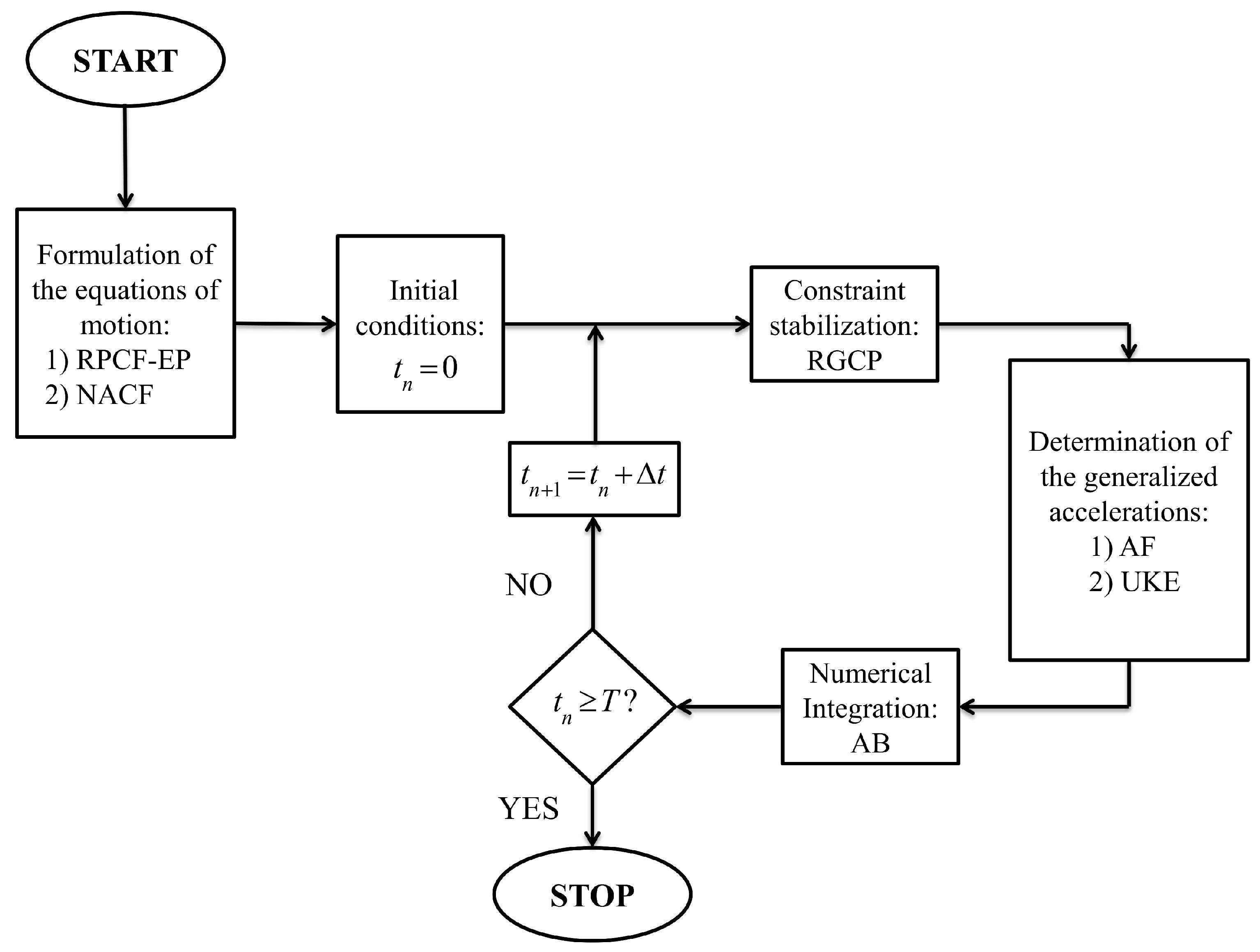
In this section, a numerical analysis is carried out in order to assess the performance and the reliability of the formulation approaches and solution methods discussed in the paper. To this end, a multibody computer code developed by the authors and programmed in MATLAB (R2013a version) is used for obtaining the numerical results discussed in this section. In Figure 1, a schematic representation of the multibody approach followed in this numerical study is shown.
In particular, the triple pendulum system represented in Figure 2 is considered as an illustrative example of a simple multibody mechanical system that undergoes a complex dynamic evolution.
Excluding the ground, the triple pendulum system represented in Figure 2 is composed of three rigid bodies and three spherical joints. As shown in Figure 2, the spherical joint collocated at the point A connects the body number 1 to the ground, while the spherical joints collocated at the points B and C serve as connections between the bodies 1, 2, and 3. The triple pendulum system is formed by three pendulums having the same geometric dimensions, namely half length , breadth , and width . The additional numerical data used for modelling the triple pendulum system are reported in Table 1.
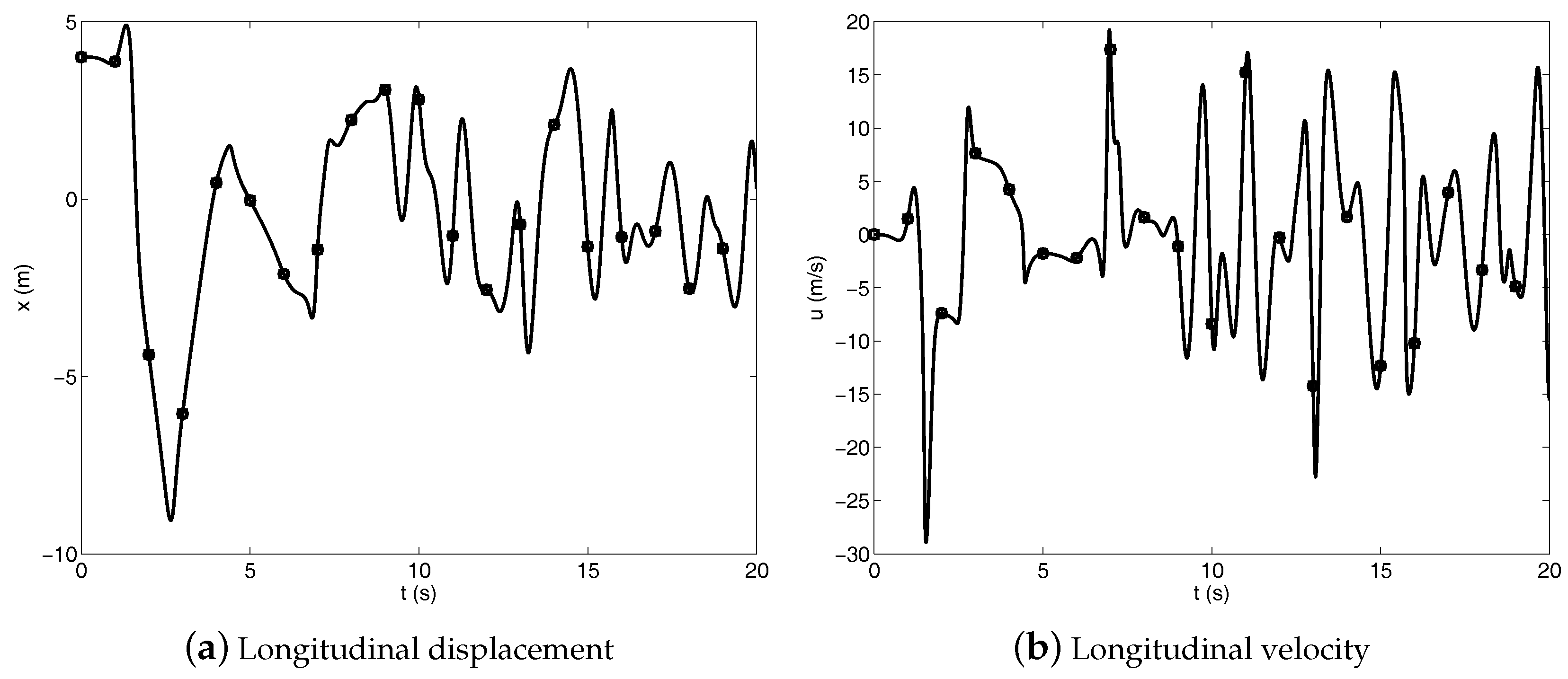
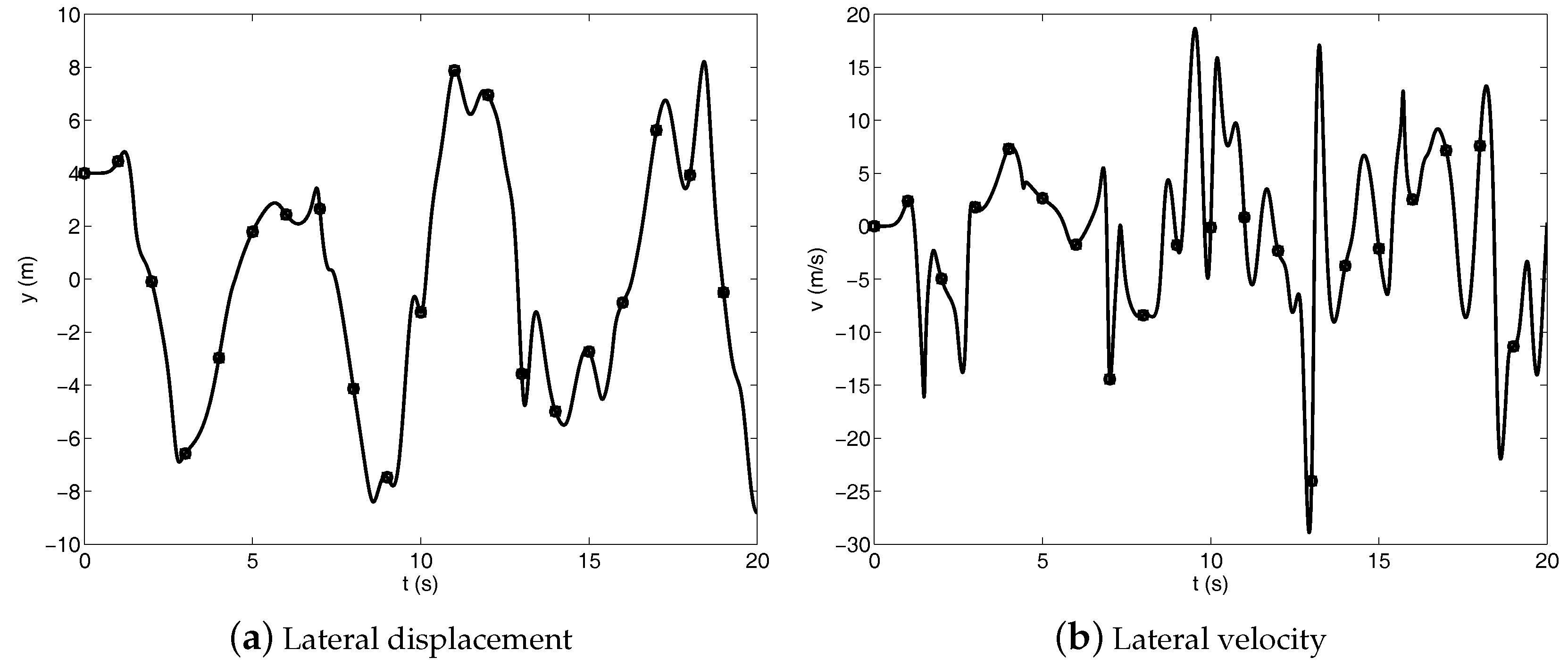
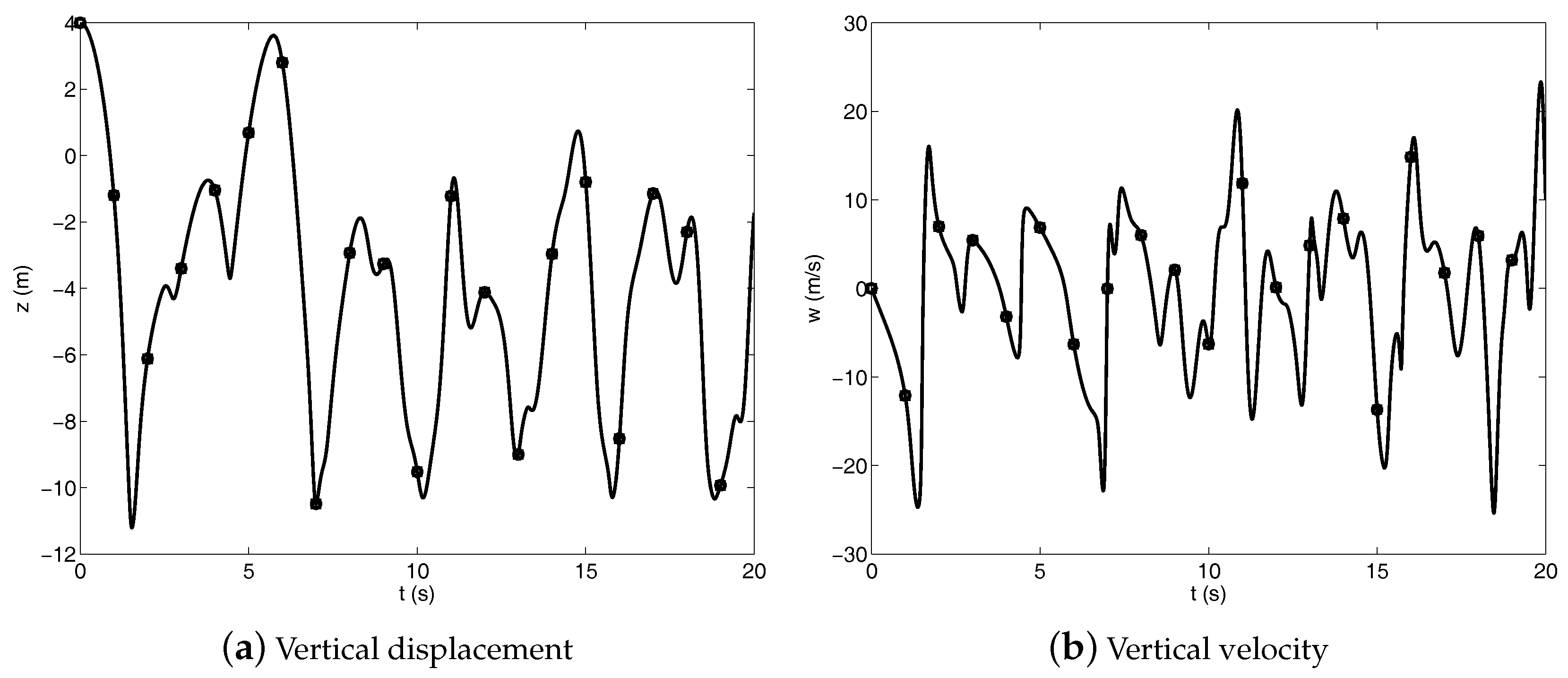
The configuration of the triple pendulum system at the initial stage of the dynamical simulation is shown in Figure 2 and the initial velocities of all the rigid bodies forming the multibody system are set equal to zero. The triple pendulum system is loaded with its own weight, which is due to a uniform gravity force field. The multibody dynamic equations of the triple pendulum system form a system of differential-algebraic dynamic equations that are analytically derived by using the RPCF-EP and the NACF. Subsequently, the Robust Generalized Coordinate Partitioning (RGCP) method is used for stabilizing constraint drift of the triple pendulum system as well as to enforce the kinematic constraints at both the position and velocity levels [60,61]. The constraint tolerance used in the Newton–Raphson (NR) numerical procedure implemented in the RGCP algorithm is equal to . Furthermore, both the AF and the UKE are alternatively used for solving the equations of motion of the triple pendulum system at the acceleration level, whereas the fourth-order Adams–Bashforth (AB) method is used for the time marching of the numerical solution of the equations of motion. To this end, a constant time step equal to is employed for performing the dynamic analysis and a time interval equal to is considered for the dynamical simulations. Figure 3, Figure 4 and Figure 5 respectively show the longitudinal, lateral, and vertical displacements and velocities of the point D at the tip of the triple pendulum system.
The numerical solutions represented in Figure 3, Figure 4 and Figure 5 refer to the dynamic equations of the triple pendulum system modelled employing the RPCF-EP and the NACF as the multibody formulation approach, whereas the system generalized acceleration vector is obtained by using the UKE as the multibody solution algorithm. The numerical solutions obtained in the comparative study shown in Figure 3, Figure 4 and Figure 5 exhibit a very good agreement and very similar numerical results are obtained employing the AF as a multibody solution algorithm. The consistency of the numerical solutions found in this work can be also observed from the trajectory of the tip of the triple pendulum system represented in Figure 6, which exhibits a chaotic motion.
Although the multibody model of a triple pendulum system is mathematically simple to derive, it is well known that this class of dynamical systems exhibits a complex physical behavior due to the nonlinearity of the equations of motion that lead to the chaos phenomenon. From a computational point of view, this property of the triple pendulum system implies that, if a small change in the initial conditions or a perturbation is induced to the numerical solution of the equations of motion because of the numerical approximations, a large difference in the resulting trajectory will be apparent in the subsequent dynamical evolution. Therefore, the simple multibody model of the triple pendulum system can be used in order to compare the numerical solution obtained employing the NACF and the RPCF-EP with the numerical solutions derived by using the AF as well as the UKE. Since there is a good agreement between the numerical solutions computed using the combination of these four different approaches, one can assume that the equations of motion are correctly solved. Therefore, the triple pendulum system can effectively serve as a multibody benchmark example in order to test the accuracy and the performance of new multibody computational algorithms by means of numerical experiments. For this purpose, in order to evaluate the accuracy of the numerical solutions obtained in this study, the norms of the constraint violations are computed for all the combinations of the methods considered in this investigation. In particular, the residuals of the constraint equations are evaluated at the position level as well as at the velocity level. To this end, Table 2 shows the maximum norms of the constraint violations for the constraint equations and their time derivatives for all the multibody methodologies analyzed in the paper.
The numerical results provided in Table 2 demonstrate that all the multibody formulation approaches and solution strategies analyzed in this study are effective since they lead to a set of numerical results that are physically accurate and numerically robust. Furthermore, the time evolution obtained by means of dynamical simulations for the multibody system considered as a benchmark example is consistent with the geometric shape of the triple pendulum system. Moreover, Table 3 shows the dimensionless computational times of all the dynamic simulations.
The numerical results reported in Table 3 demonstrate that, while the AF and the UKE show similar performance in terms of the computational times, the equations of motion formulated and solved employing the new multibody method based on the NACF lead to more efficient dynamical simulations when compared with the well-established multibody algorithm that relies on the RPCF-EP. This behavior can be explained by noticing the fact that the dynamic equations formulated by using the NACF have a constant mass matrix and the corresponding generalized inertia vector that contains the terms that are quadratic in the generalized velocities is always a zero vector.
5. Conclusions
The main topics of interest for the research of the authors are multibody dynamics, system identification, and nonlinear control [62,63,64,65,66,67,68,69,70]. This investigation represents a comparative analysis of the principal computational methodologies suitable for the analytical derivation and the numerical implementation of the dynamic equations of mechanical systems composed of rigid bodies constrained by kinematic pairs. The coordinate formulations considered in this paper are the RPCF-EP and the NACF, whereas the solution methods considered in this work are the AF and the UKE. The RPCF-EP is a well-established coordinate formulation that is used in commercial and research multibody computer codes for analyzing the dynamic behavior of mechanical systems constrained by kinematic joints. The NACF, on the other hand, is a new method recently developed by the authors by combining the key features of the well-known Reference Point Coordinate Formulation with Euler Angles (RPCF-EA) and the conventional Natural Coordinate Formulation (NCF). Unlike both the RPCF-EA and the RPCF-EP, the NACF leads to a system of differential-algebraic equations of motion in which the mass matrix is constant, while the centrifugal and Coriolis generalized inertia effects are identically equal to zero. More importantly, a straightforward formulation of the nonlinear equations that model the kinematic joints by means of algebraic constraints can be systematically obtained by using the multibody framework based on the NACF. Furthermore, the AF is a well-known multibody algorithm used for computing the generalized acceleration vector and the vector of Lagrange multipliers for a mechanical system formed by rigid bodies and mechanical joints. On the other hand, the UKE represents a new set of equations of analytical dynamics discovered by Udwadia and Kalaba. The UKE have several applications that span far beyond their original interpretation. In particular, the UKE can handle a general form of the algebraic constraint equations of holonomic and/or nonholonomic nature and can be effectively used as an efficient computational method for the numerical solution of multibody system problems. In the paper, a comparative analysis is carried out considering the combination of all the analytical formulation strategies and numerical solution approaches mentioned before. The numerical results arising from the numerical analysis carried out in this study showed that the use of the NACF as a formulation approach in conjunction with the UKE as a solution procedure represents a general, effective, and efficient computational algorithm suitable for analyzing the dynamic behavior of complex mechanical systems connected by kinematic constraints. This work represents a preliminary investigation oriented towards the future development of a more detailed comparative analysis. To this end, an array of experimental benchmark examples will be used in future investigations in order to compare the effectiveness and the efficiency of the approach proposed in this paper with the computational methods already available in the literature.
Author Contributions
This research paper was principally developed by the first author (Carmine Maria Pappalardo). The detailed review carried out by the second author (Domenico Guida) considerably improved the quality of the work.
Funding
This research received no external funding.
Conflicts of Interest
The authors declare no conflict of interest.
References
- Shabana, A.A. Dynamics of Multibody Systems; Cambridge University Press: New York, NY, USA, 2013. [Google Scholar]
- Marques, F.; Souto, A.P.; Flores, P. On the Constraints Violation in Forward Dynamics of Multibody Systems. Multibody Syst. Dyn. 2017, 39, 385–419. [Google Scholar] [CrossRef]
- Nachbagauer, K. State of the Art of ANCF Elements Regarding Geometric Description, Interpolation Strategies, Definition of Elastic Forces, Validation and the Locking Phenomenon in Comparison with Proposed Beam Finite Elements. Arch. Comput. Method Eng. 2014, 21, 293–319. [Google Scholar] [CrossRef]
- Cammarata, A.; Calio, I.; Greco, A.; Lacagnina, M.; Fichera, G. Dynamic Stiffness Model of Spherical Parallel Robots. Sound Vib. 2016, 384, 312–324. [Google Scholar] [CrossRef]
- Cammarata, A. Unified Formulation for the Stiffness Analysis of Spatial Mechanisms. Mech. Mach. Theory 2016, 105, 272–284. [Google Scholar] [CrossRef]
- Cammarata, A.; Angeles, J.; Sinatra, R. The Dynamics of Parallel Schonflies Motion Generators: The Case of a Two-limb System. Proc. Inst. Mech. Eng. Part I J. Syst. Control Eng. 2009, 223, 29–52. [Google Scholar] [CrossRef]
- Liu, C.; Tian, Q.; Hu, H. Dynamics of a Large Scale Rigid–flexible Multibody System Composed of Composite Laminated Plates. Multibody Syst. Dyn. 2011, 26, 283–305. [Google Scholar] [CrossRef]
- Patel, M.; Orzechowski, G.; Tian, Q.; Shabana, A.A. A New Multibody System Approach for Tire Modeling using ANCF Finite Elements. Proc. Inst. Mech. Eng. Part K J. Multi-Body Dyn. 2016, 230, 69–84. [Google Scholar] [CrossRef]
- Kulkarni, S.; Pappalardo, C.M.; Shabana, A.A. Pantograph/Catenary Contact Formulations. J. Vib. Acoust. 2017, 139, 011010. [Google Scholar] [CrossRef]
- De Simone, M.C.; Rivera, Z.B.; Guida, D. Finite Element Analysis on Squeal-Noise in Railway Applications. FME Trans. 2018, 46, 93–100. [Google Scholar]
- Lan, P.; Shabana, A.A. Rational Finite Elements and Flexible Body Dynamics. J. Vib. Acoust. 2010, 132, 041007. [Google Scholar] [CrossRef]
- Pappalardo, C.M.; Yu, Z.; Zhang, X.; Shabana, A.A. Rational ANCF Thin Plate Finite Element. J. Comput. Nonlinear Dyn. 2016, 11, 051009. [Google Scholar] [CrossRef]
- Pappalardo, C.M.; Zhang, Z.; Shabana, A.A. Use of Independent Volume Parameters in the Development of New Large Displacement ANCF Triangular Plate/Shell Elements. Nonlinear Dyn. 2018, 91, 2171–2202. [Google Scholar] [CrossRef]
- Liu, C.; Tian, Q.; Hu, H.; Garcia-Vallejo, D. Simple Formulations of Imposing Moments and Evaluating Joint Reaction Forces for Rigid-flexible Multibody Systems. Nonlinear Dyn. 2012, 69, 127–147. [Google Scholar] [CrossRef]
- Pappalardo, C.M.; Patel, M.D.; Tinsley, B.; Shabana, A.A. Contact Force Control in Multibody Pantograph/Catenary Systems. Proc. Inst. Mech. Eng. Part K J. Multibody Dyn. 2016, 230, 307–328. [Google Scholar] [CrossRef]
- Tian, Q.; Chen, L.P.; Zhang, Y.Q.; Yang, J. An Efficient Hybrid Method for Multibody Dynamics Simulation based on Absolute Nodal Coordinate Formulation. J. Comput. Nonlinear Dyn. 2009, 4, 021009. [Google Scholar] [CrossRef]
- Pappalardo, C.M.; Wallin, M.; Shabana, A.A. A New ANCF/CRBF Fully Parametrized Plate Finite Element. J. Comput. Nonlinear Dyn. 2017, 12, 031008. [Google Scholar] [CrossRef]
- Udwadia, F.E.; Wanichanon, T. On General Nonlinear Constrained Mechanical Systems. Numer. Algebra Control Opt. 2013, 3, 425–443. [Google Scholar] [CrossRef]
- Schutte, A.; Udwadia, F. New Approach to the Modeling of Complex Multibody Dynamical Systems. J. Appl. Mech. 2011, 78, 021018. [Google Scholar] [CrossRef]
- Pappalardo, M.; Villecco, F. Max-Ent in fast belief fusion. In Proceedings of the International Conference Differential Geometry, Dynamical Systems, Bucharest, Romania, 5–7 October 2007; Geometry Balkan Press, University Politehnica Bucharest: Bucharest, Romania, 2008; pp. 154–162. [Google Scholar]
- Strano, S.; Terzo, M. Actuator Dynamics Compensation for Real-time Hybrid Simulation: An Adaptive Approach by means of a Nonlinear Estimator. Nonlinear Dyn. 2016, 85, 2353–2368. [Google Scholar] [CrossRef]
- Strano, S.; Terzo, M. Accurate State Estimation for a Hydraulic Actuator via a SDRE Nonlinear Filter. Mech. Syst. Signal Process. 2016, 75, 576–588. [Google Scholar] [CrossRef]
- Russo, R.; Strano, S.; Terzo, M. Enhancement of Vehicle Dynamics via an Innovative Magnetorheological Fluid Limited Slip Differential. Mech. Syst. Signal Process. 2016, 70, 1193–1208. [Google Scholar] [CrossRef]
- Strano, S.; Terzo, M. A SDRE-based Tracking Control for a Hydraulic Actuation System. Mech. Syst. Signal Process. 2015, 60, 715–726. [Google Scholar] [CrossRef]
- Milosavljevic, B.; Pesic, R.; Dasic, P. Binary Logistic Regression Modeling of Idle CO Emissions in order to Estimate Predictors Influences in Old Vehicle Park. Math. Probl. Eng. 2015, 2015, 463158. [Google Scholar] [CrossRef]
- Dasic, P.; Dasic, J.; Crvenkovic, B. Service Models for Cloud Computing: Search as a Service (SaaS). Int. J. Eng. Technol. 2016, 8, 2366–2373. [Google Scholar] [CrossRef]
- Dasic, P.; Franek, F.; Assenova, E.; Radovanovic, M. International Standardization and Organizations in the Field of Tribology. Ind. Lubr. Tribol. 2003, 55, 287–291. [Google Scholar] [CrossRef]
- Dasic, P. Determination of Reliability of Ceramic Cutting Tools on the basis of Comparative Analysis of Different Functions Distribution. Int. J. Qual. Reliab. Manag. 2001, 18, 431–443. [Google Scholar]
- Serifi, V.; Dasic, P.; Jecmenica, R.; Labovic, D. Functional and Information Modeling of Production using IDEF Methods. Stroj. Vestn./J. Mech. Eng. 2009, 55, 131–140. [Google Scholar]
- Oberpeilsteiner, S.; Lauss, T.; Nachbagauer, K.; Steiner, W. Optimal Input Design for Multibody Systems by using an Extended Adjoint Approach. Multibody Syst. Dyn. 2017, 40, 43–54. [Google Scholar] [CrossRef] [PubMed]
- Villecco, F.; Pellegrino, A. Entropic Measure of Epistemic Uncertainties in Multibody System Models by Axiomatic Design. Entropy 2017, 19, 291. [Google Scholar] [CrossRef]
- Gao, Y.; Villecco, F.; Li, M.; Song, W. Multi-Scale Permutation Entropy Based on Improved LMD and HMM for Rolling Bearing Diagnosis. Entropy 2017, 19, 176. [Google Scholar] [CrossRef]
- Formato, A.; Ianniello, D.; Villecco, F.; Lenza, T.L.L.; Guida, D. Design Optimization of the Plough Working Surface by Computerized Mathematical Model. Emir. J. Food Agric. 2017, 29, 36–44. [Google Scholar] [CrossRef]
- Sena, P.; D’Amore, M.; Pappalardo, M.; Pellegrino, A.; Fiorentino, A.; Villecco, F. Studying the Influence of Cognitive Load on Driver’s Performances by a Fuzzy Analysis of Lane Keeping in a Drive Simulation. IFAC Proc. Vol. 2013, 46, 151–156. [Google Scholar] [CrossRef]
- Sena, P.; Attianese, P.; Pappalardo, M.; Villecco, F. FIDELITY: Fuzzy Inferential Diagnostic Engine for on-LIne supporT to phYsicians. In Proceedings of the 4th International Conference on the Development of Biomedical Engineering, Ho Chi Minh City, Vietnam, 8–10 January 2012; Springer: Berlin, Germany, 2013; pp. 396–400. [Google Scholar]
- Sena, P.; Attianese, P.; Carbone, F.; Pellegrino, A.; Pinto, A.; Villecco, F. A Fuzzy Model to Interpret Data of Drive Performances from Patients with Sleep Deprivation. Comput. Math. Methods Med. 2012, 2012, 868410. [Google Scholar] [CrossRef] [PubMed]
- De Simone, M.C.; Guida, D. Identification and Control of a Unmanned Ground Vehicle By using Arduino. UPB Sci. Bull. Ser. D 2018, 80, 141–154. [Google Scholar]
- Dasic, P. Examples of Analysis of Different Functions of Cutting Tool Failure Distribution. Trib. Ind. 1999, 21, 59–67. [Google Scholar]
- Dasic, P.; Natsis, A.; Petropoulos, G. Models of Reliability for Cutting Tools: Examples in Manufacturing and Agricultural Engineering. Stroj. Vestn./J. Mech. Eng. 2008, 54, 122–130. [Google Scholar]
- Zoller, C.; Dasic, P.; Dobra, R.; Pantovic, R.; Damnjanovic, Z. Sequential Algorithm and Fuzzy Logic to Optimum Control the Ore Gridding Aggregates. Tech. Technol. Educ. Manag. 2012, 7, 914–919. [Google Scholar]
- Lekic, M.; Cvejic, S.; Dasic, P. Iteration Method for Solving Differential Equations of Second Order Oscillations. Tech. Technol. Educ. Manag. 2012, 7, 1751–1759. [Google Scholar]
- Dasic, P.; Dasic, J.; Crvenkovic, B. Applications of Access Control as a Service for Software Security. Int. J. Ind. Eng. Manag. 2016, 7, 111–116. [Google Scholar]
- Zhang, Y.; Li, Z.; Gao, J.; Hong, J.; Villecco, F.; Li, Y. A method for designing assembly tolerance networks of mechanical assemblies. Math. Probl. Eng. 2012, 2012, 513958. [Google Scholar] [CrossRef]
- Sansone, F.; Picerno, P.; Mencherini, T.; Villecco, F.; D’Ursi, A.M.; Aquino, R.P.; Lauro, M.R. Flavonoid Microparticles by Spray-Drying: Influence of Enhancers of the Dissolution Rate on Properties and Stability. J. Food Eng. 2001, 103, 188–196. [Google Scholar] [CrossRef]
- Pellegrino, A.; Villecco, F. Design Optimization of a Natural Gas Substation with Intensification of the Energy Cycle. Math. Probl. Eng. 2010, 2010, 294102. [Google Scholar] [CrossRef]
- Zhai, Y.; Liu, L.; Lu, W.; Li, Y.; Yang, S.; Villecco, F. The Application of Disturbance Observer to Propulsion Control of Sub-mini Underwater Robot. In Proceedings of the ICCSA 2010 International Conference on Computational Science and Its Applications, Fukuoka, Japan, 23–26 March 2010; Lecture Notes in Computer Science. Springer: Berlin, Germany, 2010; pp. 590–598. [Google Scholar]
- Ghomshei, M.; Villecco, F.; Porkhial, S.; Pappalardo, M. Complexity in Energy Policy: A Fuzzy Logic Methodology. In Proceedings of the 6th International Conference on Fuzzy Systems and Knowledge Discovery, Tianjin, China, 14–16 August 2009; IEEE: Los Alamitos, CA, USA; Volume 7, pp. 128–131. [Google Scholar]
- Ghomshei, M.; Villecco, F. Energy Metrics and Sustainability. In Proceedings of the International Conference on Computational Science and Its Applications, Seoul, Korea, 29 June–2 July 2009; Lecture Notes in Computer Science. Springer: Berlin, Germany, 2009; pp. 693–698. [Google Scholar]
- Cattani, C.; Mercorelli, P.; Villecco, F.; Harbusch, K. A theoretical multiscale analysis of electrical field for fuel cells stack structures. In International Conference on Computational Science and Its Applications; Springer: Berlin/Heidelberg, Germany, 2006; pp. 857–864. [Google Scholar]
- Villecco, F.; Pellegrino, A. Evaluation of Uncertainties in the Design Process of Complex Mechanical Systems. Entropy 2017, 19, 475. [Google Scholar] [CrossRef]
- De Simone, M.C.; Guida, D. Modal Coupling in Presence of Dry Friction. Machines 2018, 6, 8. [Google Scholar] [CrossRef]
- Shabana, A.A. Computational Dynamics; John Wiley and Sons: Chichester, UK, 2009. [Google Scholar]
- Pappalardo, C.M. A Natural Absolute Coordinate Formulation for the Kinematic and Dynamic Analysis of Rigid Multibody Systems. Nonlinear Dyn. 2015, 81, 1841–1869. [Google Scholar] [CrossRef]
- Garcia De Jalon, J.G.; Bayo, E. Kinematic and Dynamic Simulation of Multibody Systems: The Real-Time Challenge; Springer: New York, NY, USA, 2012. [Google Scholar]
- Udwadia, F.E.; Kalaba, R.E. Analytical Dynamics: A New Approach; Cambridge University Press: New York, NY, USA, 2007. [Google Scholar]
- Pappalardo, C.M.; Guida, D. On the Lagrange Multipliers of the Intrinsic Constraint Equations of Rigid Multibody Mechanical Systems. Arch. Appl. Mech. 2017, 88, 419–451. [Google Scholar] [CrossRef]
- Udwadia, F.E.; Kalaba, R.E. A New Perspective on Constrained Motion. Proc. Math. Phys. Sci. 1992, 439, 407–410. [Google Scholar] [CrossRef]
- Pennestrí, E.; Valentini, P.P.; De Falco, D. An Application of the Udwadia–Kalaba Dynamic Formulation to Flexible Multibody Systems. J. Frankl. Inst. 2010, 347, 173–194. [Google Scholar] [CrossRef]
- De Falco, D.; Pennestrí, E.; Vita, L. Investigation of the Influence of Pseudoinverse Matrix Calculations on Multibody Dynamics Simulations by means of the Udwadia–Kalaba Formulation. J. Aerosp. Eng. 2009, 22, 365–372. [Google Scholar] [CrossRef]
- Pappalardo, C.M.; Guida, D. On the Use of Two-dimensional Euler Parameters for the Dynamic Simulation of Planar Rigid Multibody Systems. Arch. Appl. Mech. 2017, 87, 1647–1665. [Google Scholar] [CrossRef]
- Wehage, K.T.; Wehage, R.A.; Ravani, B. Generalized Coordinate Partitioning for Complex Mechanisms based on Kinematic Substructuring. Mech. Mach. Theory 2015, 92, 464–483. [Google Scholar] [CrossRef]
- Ruggiero, A.; De Simone, M.C.; Russo, D.; Guida, D. Sound Pressure Measurement of Orchestral Instruments in the Concert Hall of a Public School. Int. J. Circuits Syst. Signal Process. 2016, 10, 75–81. [Google Scholar]
- De Simone, M.C.; Guida, D. Dry Friction Influence on Structure Dynamics. In Proceedings of the COMPDYN 2015—5th ECCOMAS Thematic Conference on Computational Methods in Structural Dynamics and Earthquake Engineering, Crete, Greece, 25–27 May 2015; pp. 4483–4491. [Google Scholar]
- Quatrano, A.; De Simone, M.C.; Rivera, Z.B.; Guida, D. Development and implementation of a control system for a retrofitted CNC machine by using Arduino. FME Trans. 2017, 45, 565–571. [Google Scholar] [CrossRef]
- De Simone, M.C.; Russo, S.; Rivera, Z.B.; Guida, D. Multibody model of a UAV in presence of wind fields. In Proceedings of the ICCAIRO 2017–International Conference on Control, Artificial Intelligence, Robotics and Optimization, Prague, Czech Republic, 20–22 May 2017. [Google Scholar]
- Concilio, A.; De Simone, M.C.; Rivera, Z.B.; Guida, D. A new semi-active suspension system for racing vehicles. FME Trans. 2017, 45, 578–584. [Google Scholar] [CrossRef]
- Pappalardo, C.M.; Wang, T.; Shabana, A.A. On the Formulation of the Planar ANCF Triangular Finite Elements. Nonlinear Dyn. 2017, 89, 1019–1045. [Google Scholar] [CrossRef]
- Pappalardo, C.M.; Wang, T.; Shabana, A.A. Development of ANCF Tetrahedral Finite Elements for the Nonlinear Dynamics of Flexible Structures. Nonlinear Dyn. 2017, 89, 2905–2932. [Google Scholar] [CrossRef]
- Ruggiero, A.; Affatato, S.; Merola, M.; De Simone, M.C. FEM Analysis of Metal on UHMWPE Total Hip Prosthesis During Normal Walking Cycle. In Proceedings of the AIMETA 2017—XXIII Conference of The Italian Association of Theoretical and Applied Mechanics, Salerno, Italy, 4–7 September 2017. [Google Scholar]
- De Simone, M.C.; Guida, D. On the Development of a Low Cost Device for Retrofitting Tracked Vehicles for Autonomous Navigation. In Proceedings of the AIMETA 2017—XXIII Conference of The Italian Association of Theoretical and Applied Mechanics, Salerno, Italy, 4–7 September 2017. [Google Scholar]
Figure 1.
Multibody computational algorithm.

Figure 2.
Triple pendulum system.

Figure 3.
Longitudinal displacement and velocity of the point D at the tip of the triple pendulum system—(circle) RPCF-EP, (square) NACF.
Figure 3.
Longitudinal displacement and velocity of the point D at the tip of the triple pendulum system—(circle) RPCF-EP, (square) NACF.

Figure 4.
Lateral displacement and velocity of the point D at the tip of the triple pendulum system—(circle) RPCF-EP, (square) NACF.
Figure 4.
Lateral displacement and velocity of the point D at the tip of the triple pendulum system—(circle) RPCF-EP, (square) NACF.

Figure 5.
Vertical displacement and velocity of the point D at the tip of the triple pendulum system—(circle) RPCF-EP, (square) NACF.
Figure 5.
Vertical displacement and velocity of the point D at the tip of the triple pendulum system—(circle) RPCF-EP, (square) NACF.

Figure 6.
Trajectory of the point D at the tip of the triple pendulum system—: initial position, : final position.
Figure 6.
Trajectory of the point D at the tip of the triple pendulum system—: initial position, : final position.


Table 1.
Triple pendulum system data.
| Body Number | Mass | Moments of Inertia | Gravity Acceleration |
|---|---|---|---|
| 1 | 2 | 0.053, 2.693, 2.693, 0, 0, 0 | 9.81 |
| 2 | 3 | 0.080, 4.040, 4.040, 0, 0, 0 | 9.81 |
| 3 | 4 | 0.107, 5.387, 5.387, 0, 0, 0 | 9.81 |
Table 2.
Violations of the constraint equations of the triple pendulum system.
| AF | UKE | |
|---|---|---|
| Position Constraint Violations | (NACF) | (NACF) |
| (RPCF-EP) | (RPCF-EP) | |
| Velocity Constraint Violations | (NACF) | (NACF) |
| (RPCF-EP) | (RPCF-EP) |
Table 3.
Dimensionless computational times of the dynamical simulations.
| AF | UKE | |
|---|---|---|
| Dimensionless Computational Times | (NACF) | (NACF) |
| (RPCF-EP) | (RPCF-EP) |
© 2018 by the authors. Licensee MDPI, Basel, Switzerland. This article is an open access article distributed under the terms and conditions of the Creative Commons Attribution (CC BY) license (http://creativecommons.org/licenses/by/4.0/).
Share and Cite
MDPI and ACS Style
Pappalardo, C.M.; Guida, D. On the Computational Methods for Solving the Differential-Algebraic Equations of Motion of Multibody Systems. Machines 2018, 6, 20. https://doi.org/10.3390/machines6020020
AMA Style
Pappalardo CM, Guida D. On the Computational Methods for Solving the Differential-Algebraic Equations of Motion of Multibody Systems. Machines. 2018; 6(2):20. https://doi.org/10.3390/machines6020020
Chicago/Turabian StylePappalardo, Carmine Maria, and Domenico Guida. 2018. "On the Computational Methods for Solving the Differential-Algebraic Equations of Motion of Multibody Systems" Machines 6, no. 2: 20. https://doi.org/10.3390/machines6020020
Note that from the first issue of 2016, this journal uses article numbers instead of page numbers. See further details here.