UML-Based Cyber-Physical Production Systems on Low-Cost Devices under IEC-61499


1
Department of Electronic Engineering, Universidad Fuerzas Armadas ESPE, Latacunga 050102, Ecuador
2
FISEI, Universidad Técnica de Ambato, Ambato 180206, Ecuador
3
DISA, University of the Basque Country, Bilbao 48013, Spain
*
Author to whom correspondence should be addressed.
†
These authors contributed equally.
Machines 2018, 6(2), 22; https://doi.org/10.3390/machines6020022
Submission received: 24 March 2018
/
Revised: 23 April 2018
/
Accepted: 25 April 2018
/
Published: 27 May 2018
(This article belongs to the Special Issue Smart Manufacturing, Digital Supply Chains and Industry 4.0)
Abstract
:Current industry must improve the day-to-day control and industrial communications of its processes in order to bring itself closer to the Industry 4.0 paradigm. To attain these improvements, which aim towards obtaining agile and intelligent manufacturing systems, the IEC-61499 standard is considered to be the main option by many researchers. Despite its benefits, its biggest drawback is the lack of software tools required for an effective design process for distributed control systems. The following work details the implementation of the IEC-61499 standard in low-cost devices using 4DIAC-FORTE for distributed control of a FESTO MPS 200 educational system, by using Unified Modeling Language (UML) diagrams as a software tool for modeling the function blocks (FBs) of the IEC-61499 standard. This work demonstrates a simple and easy way to create distributed systems.
1. Introduction
Currently, at the industrial level, automatic control of systems or processes is carried out using programmable logic controllers (PLCs) that fulfill a specific assigned function [1]. In addition, control of the plant is centralized within the executed algorithms. The constant growth of technology and the need to reduce cost with the aim of maximizing production have forced industries to look for systems that allow a boost in capacity and smaller-sized devices with greater flexibility and robustness. This is why low-cost embedded operating systems were developed and are generally freely available.
Low-cost devices that have an internal embedded operating system have several advantages over known programmable controllers [2,3]. Embedded systems have advantages in terms of size, cost, performance, and level of management.
They are able to provide a greater ease of programming to the user, they require remarkably less space to operate, they contain sufficient assurances to work even in harsh environments, they do not require a fully specialized labor force, and the cost of implementation is much lower than the implementation of control through a PLC [4].
Among the initiatives that compose Industry 4.0, one of the most projected technologies is the integration of cyber-physical production systems (CPPSs) [5]. CPPSs are comprised of control devices with extensive computing and communication capabilities, both local and remote. One of the standards that allows for the design of CPPSs is IEC-61499, which is based on models, the function block (FB) being one of its fundamental models. This model encapsulates all the algorithms and data, which compensates for the absence of global variables since when using FBs, variables can be relocated and adapted to the new conditions that the process may require. Interoperability, reconfigurability, and portability are the basic characteristics for development of the IEC-61499 standard.
In the domain of automation using IEC-61499, models are organized hierarchically and hence FBs must be connected in this way. To achieve this goal, software tools widely used in the design of computer systems, such as Unified Modeling Language (UML), should be employed [6]. This language is used to produce an architecture of generic models for the control of industrial processes, which will guide the connection and design of a distributed control system based on FBs.
This paper proposes a combination of UML and the IEC-61499 standard. According to Panjaitan and Frey [7], UML proposes a development process and provides design models which, when following IEC-61499, allow for the complete implementation of a distributed CPPS automation control system exactly suited to the process it was designed for. Additionally, implementation is done in a simple way and with less engineering hours spent.
The layout of this paper is as follows, Section 2 shows some related work that was used as a starting point for this research. Section 3 reviews the state-of-the-art work related to the main aim of the research. Section 4 illustrates a case study and a proposed solution, which details the hardware and software elements used in this work to achieve an implementation of the IEC-61499 standard in a low-cost control system, using flexible model architecture development with the help of UML. Finally, conclusions and ongoing work are described in Section 5.
2. Related Work
This section analyzes the research and work directly related to the areas in which IEC-61499 has been used. It also describes the approach and scope of the research proposed in this work, the development of a methodology based on IEC-61499, and a CPPS architecture for the planning of distributed processes.
In Reference [8], the way in which the IEC-61499 standard is based on interoperability and its flexibility for service-oriented architectures are discussed via case study. Discussion topics comparing IEC-61499 and IEC-61131-3 are presented. While IEC-61131-3 standardizes the programming languages and is proprietary, the IEC-61499 standard satisfies the current need to make compatible control devices independent of the commercial house they belong to.
Considering the point of view of Reference [2], in which IEC-61499 is analyzed, this paper presents semantics with all the drawbacks that may occur when making use of the standard . Firstly, for the standard under discussion, the function blocks (FBs) that are used to encapsulate the information allow direct improvement of the purpose of its predecessor IEC-61131-3, as explained in [9]. In addition, in this article a comparison is made between the low-cost devices with embedded systems and programmable controllers, which verifies the utility and power of the IEC-61499 standard.
Some research has recently been published on the design, use, and implementation of function blocks using the IEC 61499 standard for different control applications [10]. Most of these investigations have been limited to performing basic control with the supervision of programmable automata (PLCs) in an industrial process [11]. However, these devices have the disadvantage that, by design, they are not able to handle uncertainty problems or the design and planning process at the factory level in an industrial production process. According to the literature consulted, systems designed under IEC 61499 have limited use for adaptive processes and for the control of basic systems [12]. For this reason, the aim of this work is to design and implement a control system under IEC 61499 in a real continuous process.
In [6,13], UML is used to design the models and architecture of an automation system. This approach has a disadvantage because new control and automation engineers do not know how to perform automation applications using this type of language. Engineers now understand and use concepts and languages defined by IEC 61131. In previous research undertaken by Thramboulidis and Tranoris in [14], a UML use case driven approach was used. The proposed approach integrates UML with the FB construct (already well-accepted by control engineers) to cover the analysis and design phases of the development process. However, none of the above researchers has proposed a way of implementing the FB-based design specifications of control applications.
Different works involving FB networks under IEC 61499 cover aspects such as the design of distributed autonomous systems with intelligent control components [9], the maintenance of distributed control systems and web-based engineering [15], the automated verification of industrial control systems [1], support systems engineering [16], and the modeling of reconfigurable concurrent systems [17].
The following work uses the starting point marked in Reference [18] to extend the scalability of the standard to more low-cost devices by using class diagrams and UML execution to design the system of distributed control. This methodology verifies that all the results achieved by the aforementioned research groups are implementable in different types of low-cost devices, thus continuing with the line of study initiated.
3. State of the Art
3.1. IEC-61499
IEC-61499 is a new architecture designed to replace the IEC-61131-3 standard. Its main focus is the design of control applications in distributed form. The new standard proposes operation based on FBs characterized by their inputs, outputs, and functions performing internally. Each FB encapsulates the control algorithms in functions based on incoming input events, setting the difference with its predecessor IEC-61131-3, which works based on the periodic verification of subroutines [19].
The IEC-61499 standard aims to provide three important aspects [20], as follows.
- Portability: Software components and configurations of distributed applications can be interpreted and supported by different development environments.
- Configurability: The configuration of any device along with its control software can be executed by development tools from several IEC 61499 software suppliers.
- Interoperability: The control applications under IEC 61499 can be executed by several hardware platforms with embedded operating systems to work together and reach the aim of distributed application.
IEC 61499 improves a distributed system architecture by defining a generic and hierarchical structure for distributed control applications. The models presented in the standard are generic, independent from the domain, and extensible in order to make it suitable for several distributed applications. The models are: (i) Function Block Model (FB), (ii) Resources Model, (iii) Device Model, (iv) System Model, (v) Application Model, (vi) Distribution Model, and (vii) Management Model. See Figure 1.
The FB model is the primary and elementary model of the standard. FBs are functional units which encapsulate algorithms working with a group of input/output events and input/output data. FB-based architecture for control devices enables a modular design approach and makes the development process easier and more efficient. However, since IEC 61499 is a conceptual reference model for general purposes, it is necessary to establish model-derived class FBs for a particular application based on an object-oriented view.
Several systems can be designed using the FB model in IEC 61499 architecture. The user can create application models using an FB network. The nodes of this network are Compound FBs (CFBs) or Service Interface FBs (SIFBs). The joining of one or more “local applications” with communication interfaces creates a resource model. A device model contains one or more interfaces (communication interface or process interface) and one or more resources.
The IEC-61499 standard makes it possible to model control applications by encapsulating the information in the FBs, and visualize the interconnections between the components involved. It is important to mention that there are certain dependencies within the standard, such as SIFBs that depend directly on the platform where they are executed. These dependencies can be disadvantages in the norm because a model is not supposed to depend on any execution platform.
3.2. UML for Modelling Control Systems
UML is considered to be an appropriate language for modeling automation systems, and at the same time as an extension of the IEC 61499 standard specifications through UML. UML allows the explicit definition of the system hierarchy as a class diagram, making it possible to represent in UML any distributed structure architecture in function blocks. Sequence and cooperation diagrams can be used to specify the desired behavior, which are not available in IEC-61499 [21]. In addition, it is possible to use UML as a query language of specifications (for model validation and testing) and as a structural and functional constraint language (for the synthesis of correct models).
Application rules for diagrams and specific semantics limit its use within other application domains. The approach introduced in this paper is based on the following assumptions: (i) FBs and other structures of IEC 61499 are used to describe an “executable specification” of a control system. (ii) The UML is used as a language that supports the engineering process: modeling, design, and maintenance of the automation system. Additionally, both UML and IEC-61499 use the typing/instantiation concept not only for the data but also for the code capsules. It is implicitly assumed that the UML class concept corresponds to the function block concept of IEC 61499 and vice versa.
The UML used for modelling IEC 61499 control systems involves the following types of diagrams: class diagrams, sequence diagrams, cooperation diagrams, and state charts. Class diagrams are used to represent the structure which includes: (i) the full hierarchy of functional system components (defined by the aggregation and inheritance of relations); (ii) types of function blocks, sub-applications, adapter interfaces, resources, and devices; (iii) system, device, and resource configurations; (iv) FB interfaces including event and data inputs and outputs and the corresponding qualifiers; (v) connections between FBs typical for instances of given types; (vi) constant data representing input parameters of function blocks, sub-applications, resources, and devices. Sequence and cooperation diagrams are used to support the definitions of the application dynamics and their transformation into the connections between FBs, parameters corresponding to FBs, and resources or devices deployment at distributed systems.
UMLs are used to generate sequence diagrams for describing the behavior of SIFBs and are applied in correspondence with the paradigm of IEC-61499 FBs under ISO TR 8509 [22]. Using the cooperation diagrams (extended with text constructions in the connections), it is possible to define point-to-point connections between function blocks. UML state diagrams are used to specify the exact behavior of the components, which are determined by the execution control charts (ECCs) of the basic FBs. According to the ECC structure, UML state tables become quite simple: they do not include compound and historical states, nor do they include complex transitions.
4. Case Study
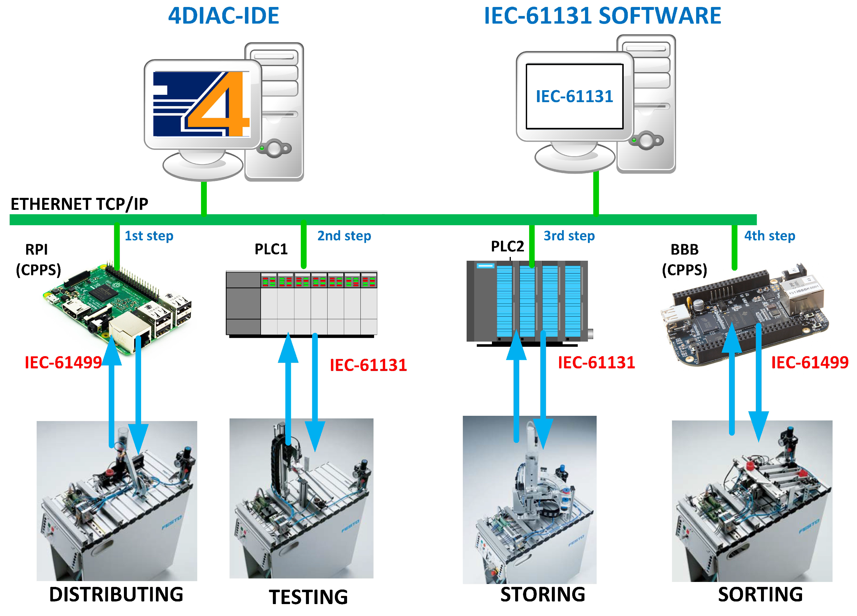
The proposed case study describes a scale factory automation system. The production plant is an assembly line with four FESTO FMS-200 stations. Distribution, selection, storage, and sorting stations are used. The operation of the model is based on a serial execution of each of these processes to complete one cycle of its global work loop, and in this way to simulate a batch process. A working cycle comprises: the distribution of the working material, separation of the defective units from the process by means of a selection based on the height of each piece, transporting the materials without defects to the storage process, followed by the classification of the different materials based on their color characteristics. With the color classification ended, a cycle of the working loop ends to make way for a new one, as shown in Figure 2.
To be able to have a point of comparison between the controllers implemented in the low-cost devices under IEC 61499 and those that were implemented under the guidelines of IEC-61131, the controllers of testing and storing stations remained unchanged, while for distribution and classification stations, low-cost CPPSs such as BeagleBone Black and Raspberry Pi were used.
4.1. Hardware Platform
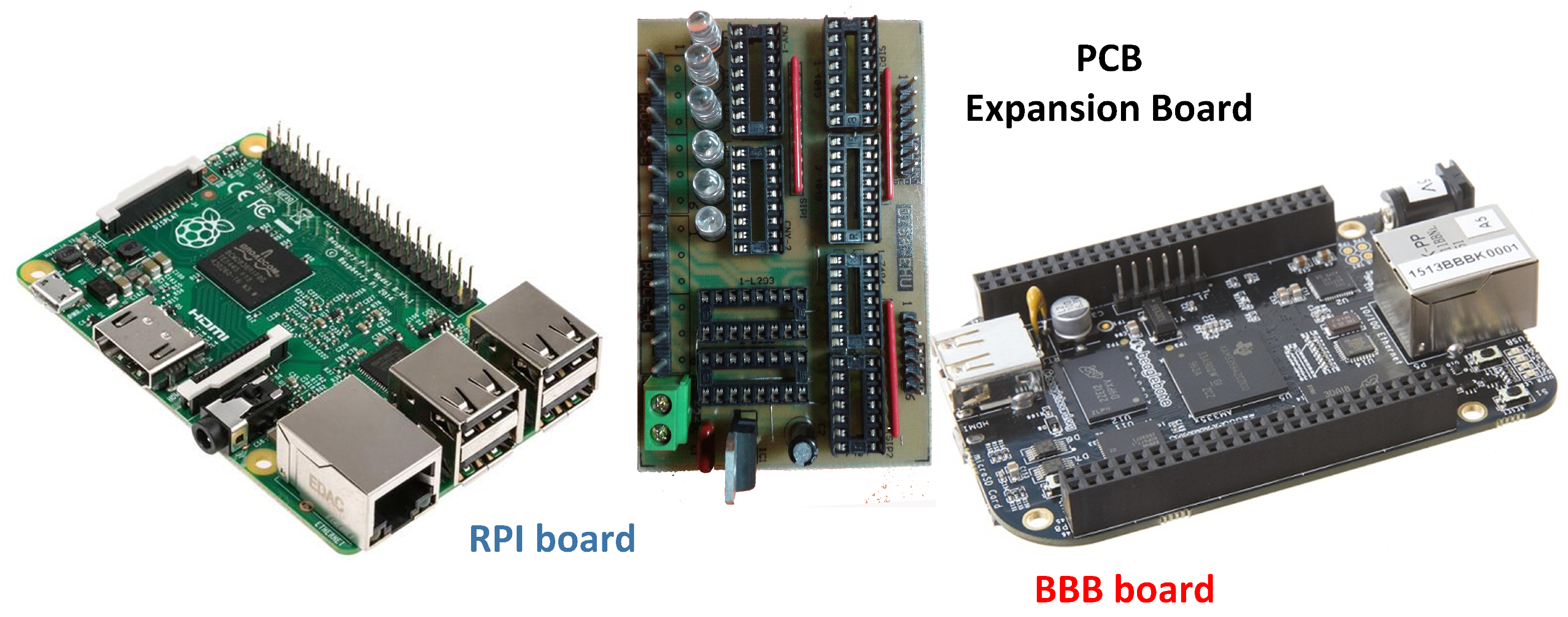
One of the main aims of this work is the usability expansion of the IEC-61499 standard to a higher number of low-cost devices. Raspberry Pi (RPI) and BeagleBone Black (BBB) cards are considered by many researchers of the automation field as excellent prototypes for industrial control due to their low cost, reduced size, and great computing performance. Besides these characteristics, both of the cards are chosen because of their capacity to work with embedded software.
Both Raspberry Pi and BeagleBone Black cards are able to work with many Linux distributions, making them more versatile. Additionally, they have a considerable number of general-purpose I/O ports (GPIO): 26 ports in the RPI and 65 ports in the BBB that allow interaction with the physical world. One of the disadvantages of both cards is that their kernel does not allow direct manipulation of their I/O ports, but this can easily be offset by the wide variety of libraries developed to manage these ports. Table 1 presents a comparison of the features of each card.
However, in order to make working with industrial signals possible, an expansion board is required. In this case, a board providing 12 digital inputs and 12 digital outputs of 24 V was used (Figure 3).
4.2. Software Platform
Within distributed control, software capable of compiling under the implemented norm is required. 4DIAC-IDE is an integrated development environment (IDE) for the design of applications with distributed control based on Eclipse, with a wide variety of plug-ins which can be attached to fulfill its extensible function. In this software, the FBs of the IEC-61499 architecture are developed, with which the entire application is developed through networks of FBs.
The open structure for distributed industrial automation and control (4DIAC-IDE) aims to promote the implementation of the IEC-61499 standard in manufacturing processes, automation at the domestic level, and even in energy systems [23]. In addition, 4DIAC is considered to be software that meets all the new requirements, adapting with great ease to the global market, as well as Industry 4.0.
4DIAC-IDE works with its FORTE (4DIAC-RTE) runtime, whose strength is that this runtime can be run on several operating systems, whether embedded or not, including Windows, Linux, NET + OS7, or eCos, as well as on different hardware platforms like Weidmüller PLC, Wago PLC, Raspberry Pi, BeagleBone Black, and LEGO Mindstorm NXT. For the development of the distributed control, it is necessary to execute FORTE on each of the nodes that integrate the application.
4.3. Use of UML for Designing FB and CPPS Control Systems
With the help of UML, specifically by using class diagrams, we will proceed to model the physical architecture of the FESTO MPS 200 system, used as a case study.
Classes are interrelated to each other in specific ways. Relationships in class diagrams include different types of logical connections. The following are types of logical connections that are possible in UML: aggregation or composition, inheritance, association, and dependency. FBs of IEC 61499 and applications architecture are completely defined using the UML relations of aggregation or composition. These UML relations define a complete hierarchy of FB type classes, but also determine the hierarchy of objects (i.e., instances of FBs) that is achieved using aggregation connections roles. The instance of an FB corresponds to the name of the role used in a UML class diagram. Consequently, the number of instances of an FB type is determined by the number of aggregation links used in FB classes.
In the IEC 61499 architecture, the event, data, and adapter connections between FBs are determined by association relation, an associative link where each value is an instance of the corresponding FB type. An association link can be of EVENT, DATA, or ADAPTER type.
UML inheritance used in IEC 61499 is an important concept in object-oriented design, and refers to the ability of one FB class to inherit the identical functionality of another class, such us: data, event, and inputs and outputs, and obviously then add new functionality of its own.
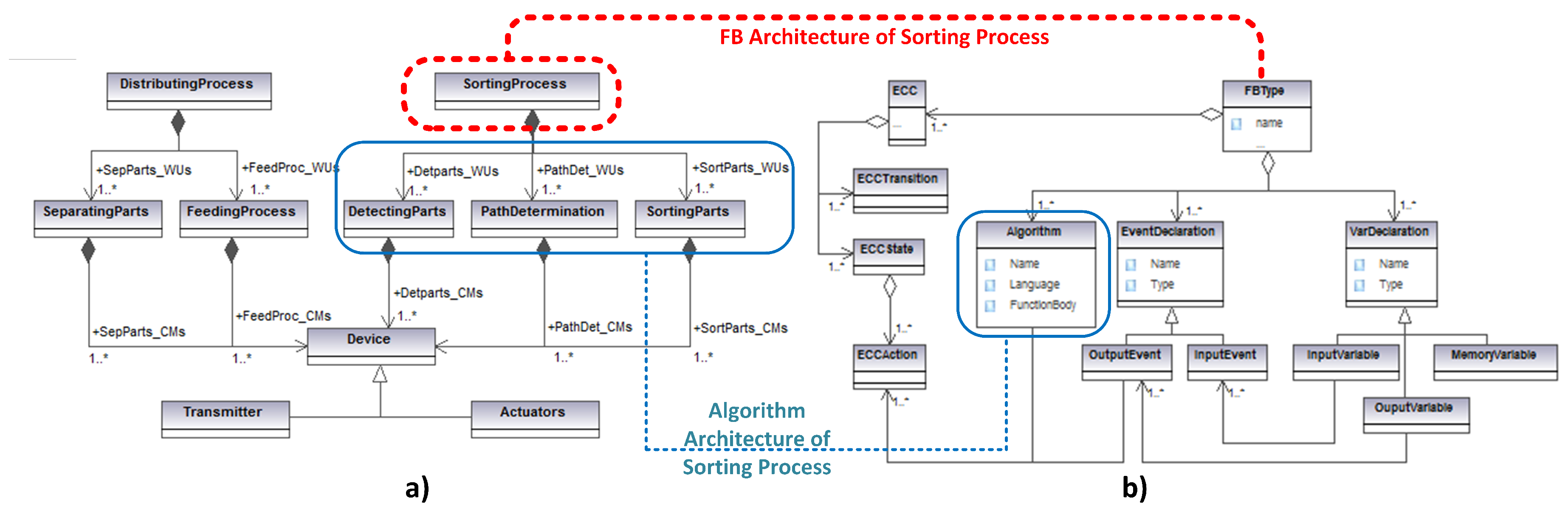
Using the previously explained relations, the stations for the processes of distributing and sorting were modelled in which the FBs were implemented according to the IEC-61499 standard. This is depicted in Figure 4a.
The physical system architecture of the distributing process includes two phases which have an association relation. (1) The first phase is called Separating Parts, and separates the parts located in a stockpile. The device used in this procedure is a double-effect cylindrical actuator. From Figure 4 it can be seen that it is linked to the process class by a composition relationship. The position of this actuator is detected by magnetic inductive sensors, the sensors and actuators are related with the device class by inheritance. (2) The second phase identified in the architecture is the Feeding Process. This phase is composed of a spinning actuator of 180. This actuator transports process parts from the stockpile to the next station’s entrance. This device has two inductive sensors for detecting the position. (3) Finally, a vacuum allows parts to be held for their transportation.
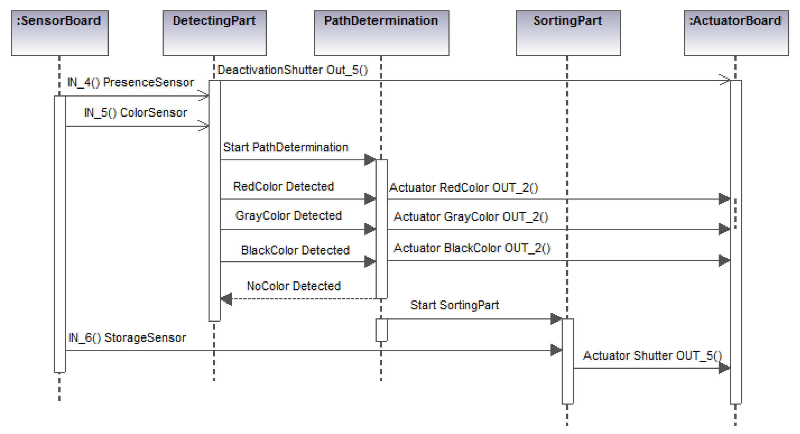
Like the previous process, the sorting process was modelled using the relationships of the UML. This station separates the parts into three storage ramps, and it has three phases, as shown above. (1) The Detecting Parts phase uses a reflective sensor and identifies the part color. The parts used in this process were of three colors: black, red, and silver. (2) The next phase is the Path Determination phase, where algorithms allow the determination of which path to follow to get to the storage ramp according to the color detected. (3) The final phase is called Sorting Parts. It uses a pneumatic shunt that redirects the parts to the correct ramp.
Once the physical architecture of the MPS 200 system was modelled, we proceeded to model the logic architecture of the FBs based on the IEC-61499 standard which was used for the control of each of the stations. This architecture is shown in Figure 4b.
Function Block Type (FBType) and Function Block Instance (FBInstance) classes are depicted in Figure 4. These classes are used for the development of IEC 61499 applications in 4DIAC-FORTE runtime. Function Block Type classes encapsulate internal variables and tags, industrial control algorithms, and their behavior is triggered by Execution Control Charts (ECCs), which are event-driven state machines. ECCs react to input events and achieve actions using internal algorithms to generate the appropriate outputs. Furthermore, this class contains event inputs and outputs in addition to data inputs and outputs. All this information is used by the Function Block Instance class constructor to implement FB instances of a given type. These instances store values for the input and output tags of the FB. The “kernel module” mechanism of operating systems such us Linux, Windows IoT, RISC OS, etc. are used for the runtime loading of FB types.
4.4. Generation of a SIFBs Set for IEC-61499 Following a UML Class Diagram
Using the development environment of the software tool 4DIAC-IDE and a meta-model developed in a previous step, a group of FBs was implemented encapsulating the I/O functions for both cards, as well as some control functions for the two different processes where the cards were used. This kind of approximation aims to leave any process involving hardware behind multiple networks of FBs under the IEC-61499 standard, in the same way that it encloses all the modeling of control recipes behind multiple lines of code for the generation of the respective machines of states of both distribution and classification processes.
Using the UML methodology described in the previous sections [24], we identified the services that the SIFB was going to implement. Furthermore, we could define the SIFB inputs and outputs (i.e., the event inputs, data inputs, event outputs and data outputs needed to provide the services). In addition to that, using this UML-based methodology, the service primitives were specified, including the definition of a sequence of service primitives jointly with its associated data. This definition must take into account both normal and abnormal conditions.
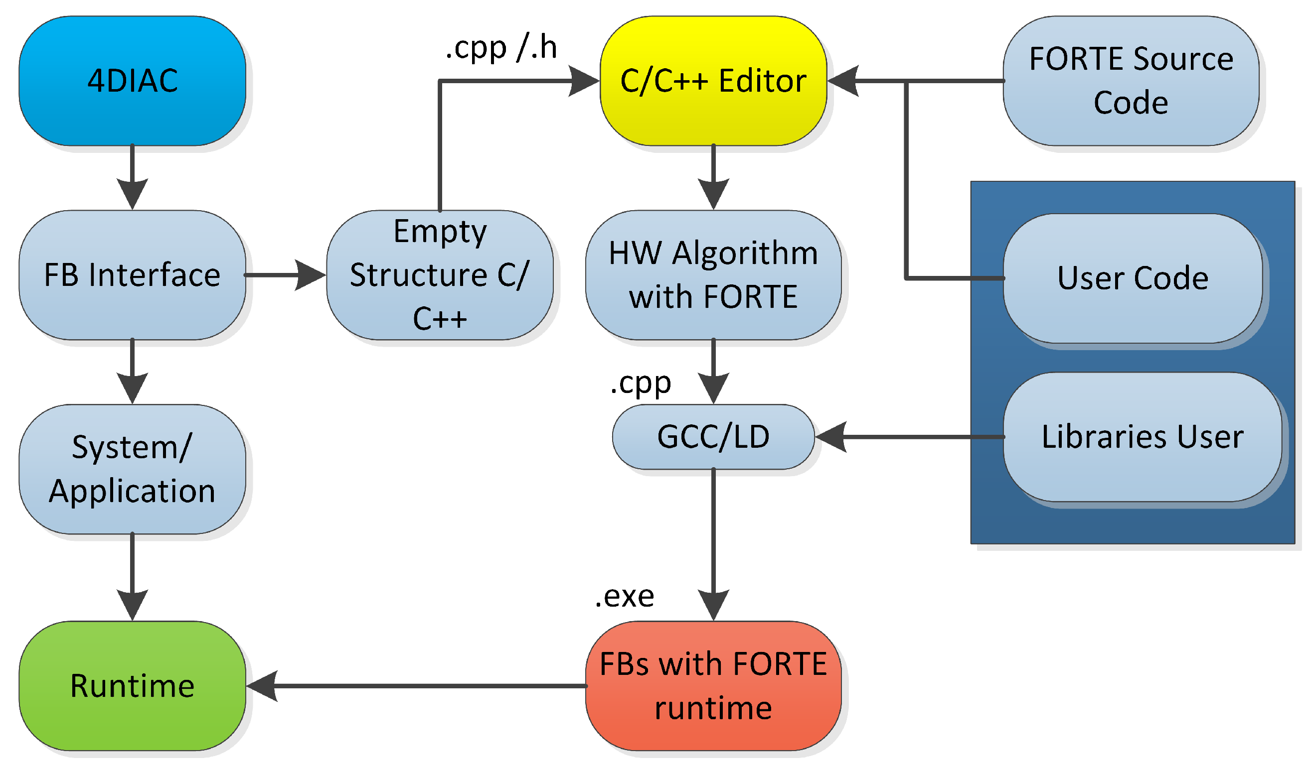
As a result of these steps, an empty C++ structure for a FB was generated according to the FORTE runtime model. The next step involved defining the IEC 61499 methods that link the algorithms to the hardware as well as including the functions that link the C/C++ code to the FORTE runtime. A general scenario of this last part of the methodology can be seen in Figure 5.
Under this work mode, we worked with two FBs groups: (1) FBs for I/Os manipulation of the cards and (2) FBs for batch control.
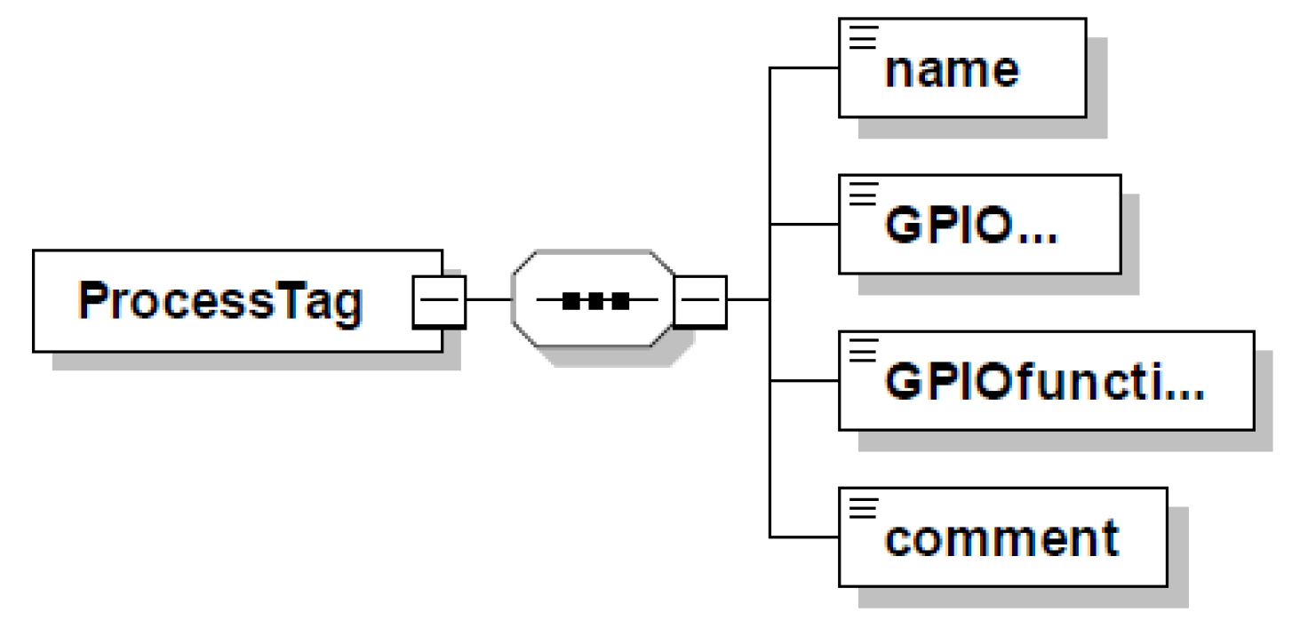
- FBs for I/Os manipulation.This group of FBs was designed to use the GPIO ports of each card allowing them to interact with the outside process according to the control actions required by the implemented controllers. With the purpose of working with the commonly used regulations in the current industry and easing its implementation, a configuration XML file was generated to map I/Os for each card. The XML file contained information about: (1) access name to the variable; (2) name of the pin corresponding to the GPIOs in each card; (3) port function; and (4) a brief comment (Figure 6).
- (a)
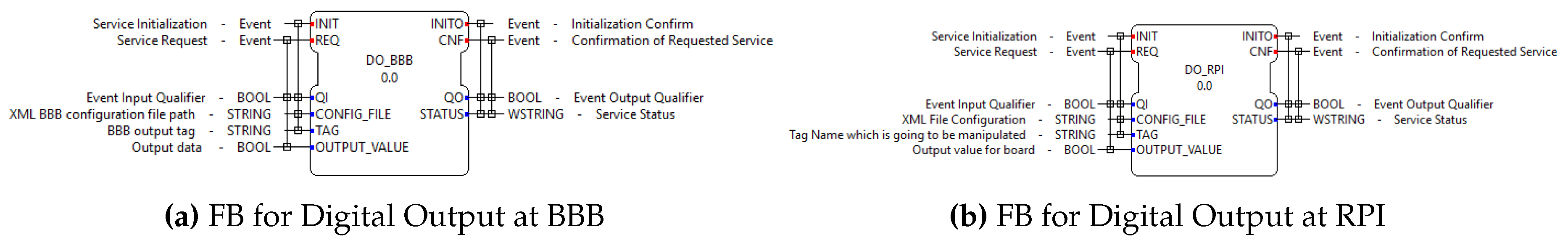
- DO_BBB and DO_RSP FBs. They are used to configure the GPIO ports required as digital outputs, by writing on them a logic value TRUE or FALSE. As with the standard FBs, these FBs receive the INIT and REQ events to start their operations, and they generate the INITO and CNF events. These FBs work with the following I/O variables (see Figure 7a,b):
- CONFIG_FILE (Input, STRING): XML filename with the information of each card’s mapping.
- TAG (Input, STRING): Output port name to manipulate.
- OUTPUT_VALUE (Input, BOOL): Boolean value to be written on the GPIO port.
- STATUS (Output, WSTRING): Error description code whenever there is one.
- (b)
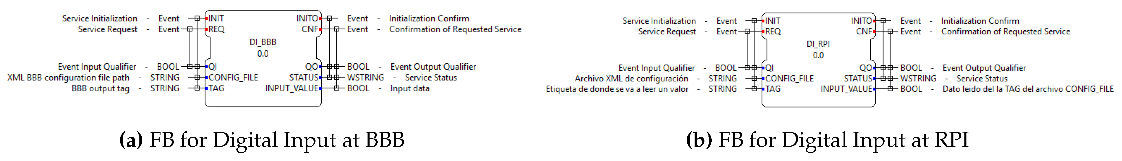
- DI_BBB and DI_RSP FBs. Their function is to configure the GPIO of the corresponding card as data entry, and when invoked, they read the input digital value in the port. As with the standard FBs, these handle the INIT and REQ events to start their operations and they generate the INITO and CNF events. These FBs work with the following I/O variables (see Figure 8a,b):
- CONFIG_FILE (Input, STRING): XML filename with the information of each card’s mapping.
- TAG (Input, STRING): Output port name to manipulate.
- INPUT_VALUE (Output, BOOL): Boolean value read on the GPIO port.
- STATUS (Output, WSTRING): Error description code whenever there is one.
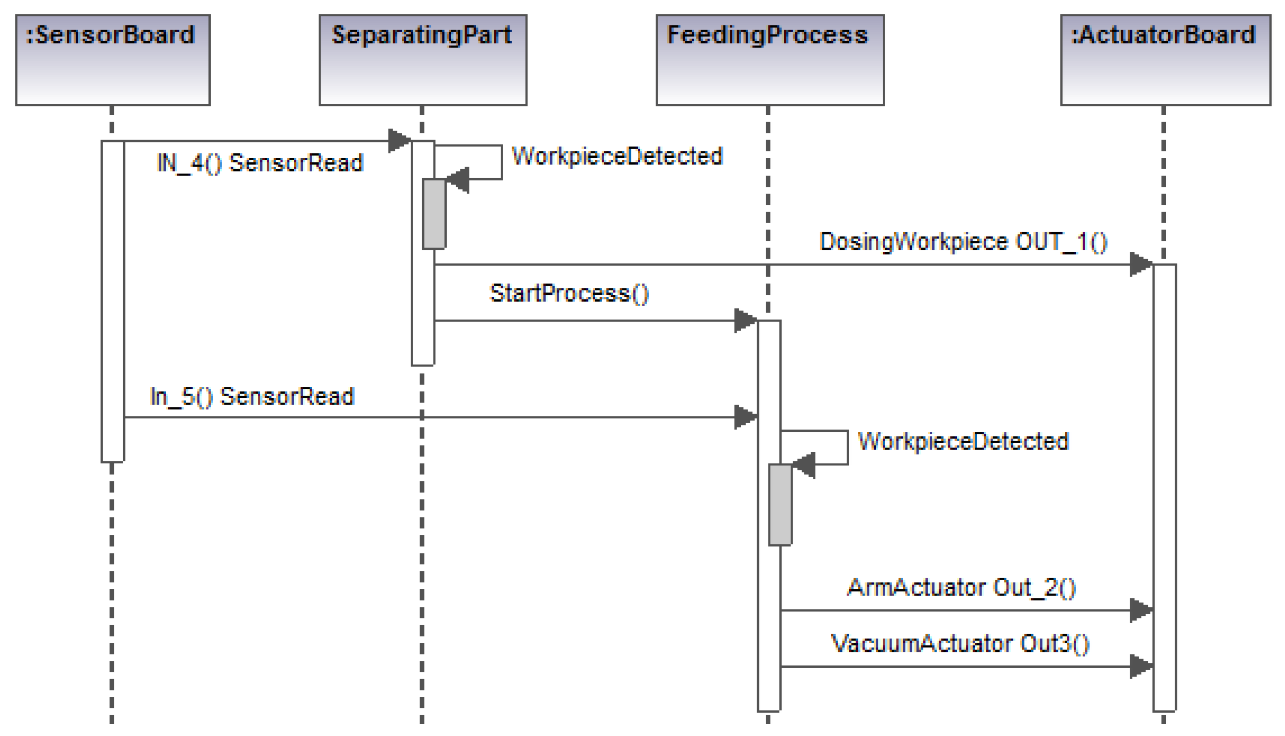
- FBs for batch control.This kind of FB uses control algorithms based on the meta-model developed in Figure 4a,b, which belong to the Distribution and Sorting stations. These FBs allow the algorithms’execution as long as the necessary conditions are met for each action to execute. As a first step, the scenario that the control algorithm must implement was designed. For this, the UML sequence diagram was used. In this diagram, the iteration of the FBs inputs with the control algorithm and the outputs that it could generate are shown. The sequence diagram contains the control algorithm’s implementation details, including the classes and diagrams designed in the previous steps and finally it indicates the responses of each of the classes involved in the control.
- (a)
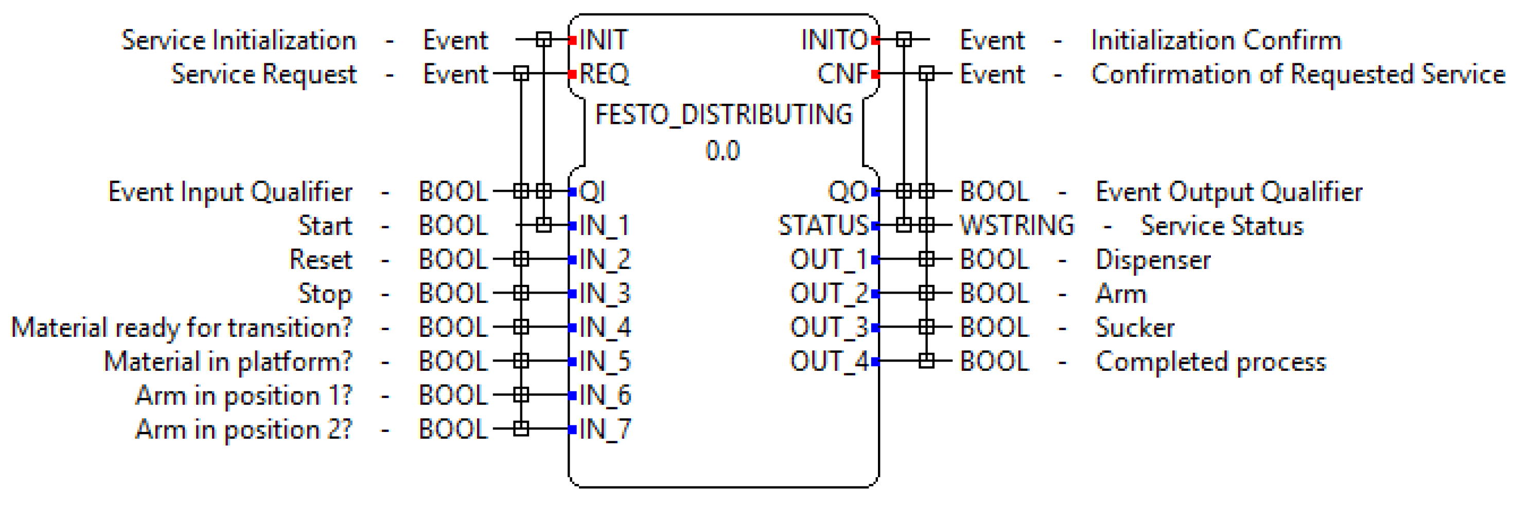
- DISTRIBUTING FB. Inside this FB, the control algorithm corresponding to the process of the Distribution station is encapsulated. Figure 9 specifies the identified phases when analyzing the functioning of this station. The phases analyzed according to the UML sequence diagram allow determination of the number of inputs and outputs of the FB and its possible behavior.As with standard FBs, this receives the INIT and REQ events to start its operations and it generates the INITO and CNF events. There is also a set of channels to manage the I/O data, which are described in Figure 10.
- (b)
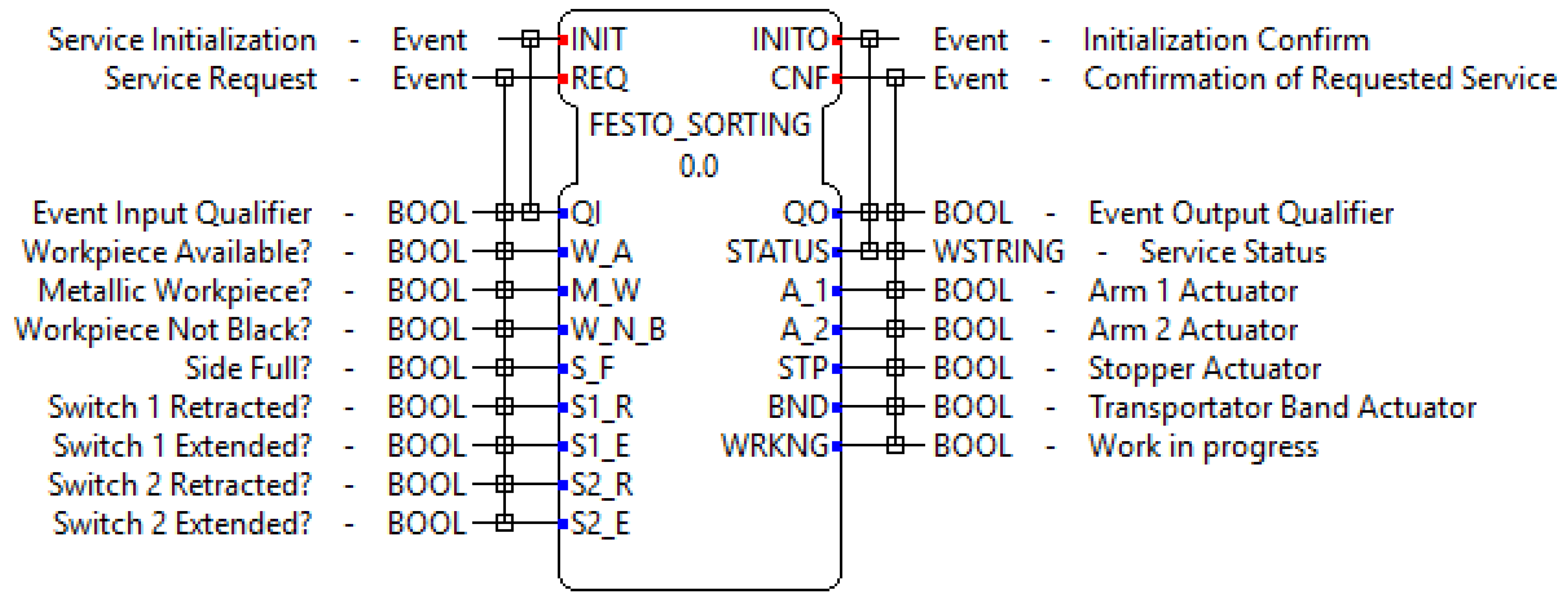
- SORTING FB. Inside this FB, the control algorithm corresponding to the process of the Storing station is encapsulated. Figure 11 specifies the identified phases when analyzing the functioning of this station.As with standard FBs, this receives the INIT and REQ events to start its operations and it generates the INITO and CNF events. There is also a set of channels to manage the I/O data, which are described in Figure 12.
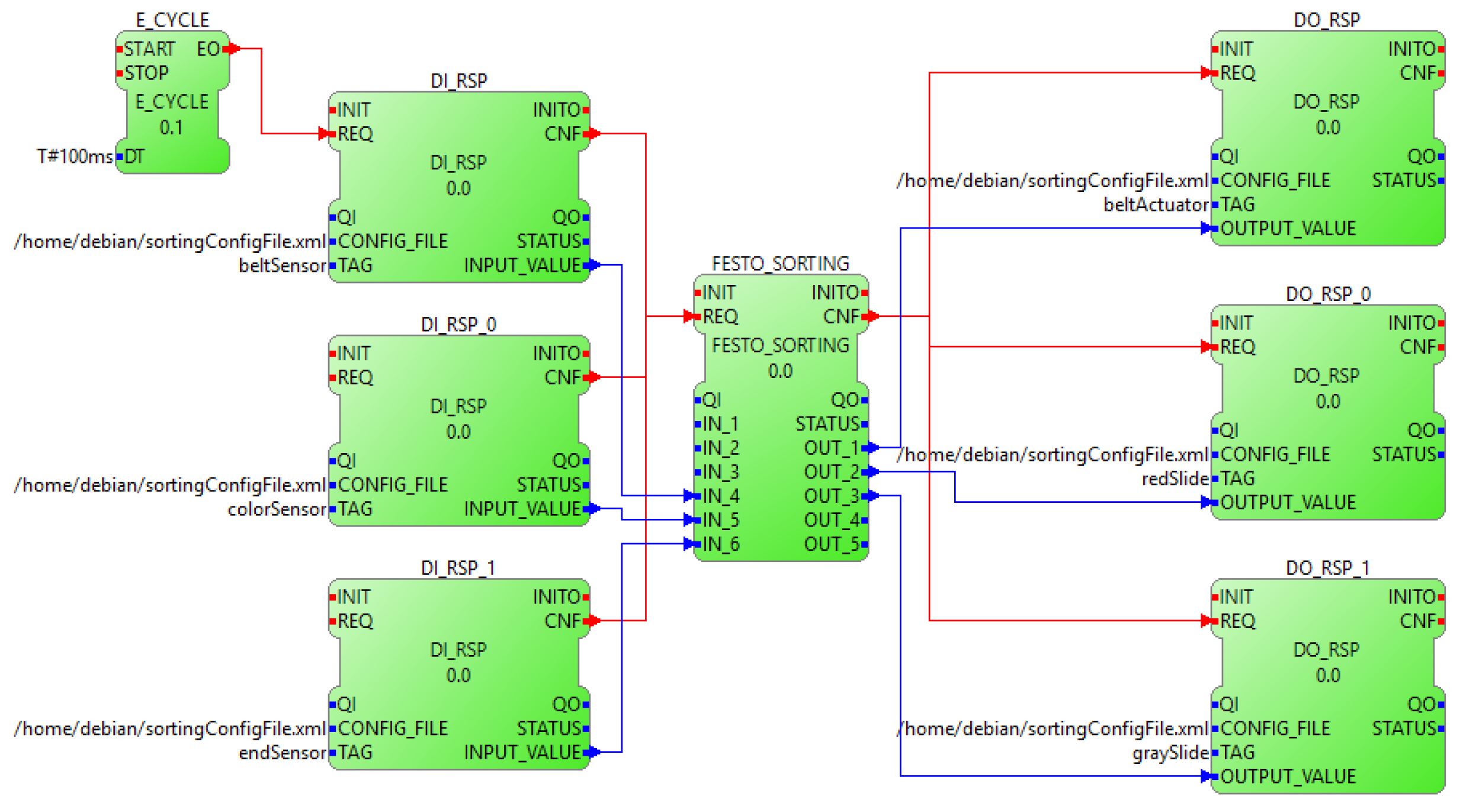
- IEC-61499 Network FBs.With all the core I/O and control SIFBs generated, in order to create the control applications for each module, it is necessary to interconnect them to follow the operation structure of: reading of inputs, data processing, and writing of outputs. All of the generated SIFBs work under the execution of the events INIT and REQ. The algorithms codified inside the respective INIT events of the FBs contain the operations in charge of configuring the logical resources which allow the development boards to interact with the physical environment, to be properly used all along the execution of the FORTE runtime environment. A continuous generation of the INIT events represents a waste of time in unnecessary reconfigurations of resources. This is why this process needs to be done only once in the first cycle of execution.On the other hand, the REQ events contain the programming related to the manipulation of the resources pre-configured in the INIT event (read of inputs and write of outputs) and the calculations of control actions based on the system inputs.Figure 13 and Figure 14 show the block connections done in order to obtain the desired operation structure. An execution control FB is used to periodically generate the trigger signals in charge of starting the activation of the REQ events sequence. With the REQ event activation, the I/O FBs start their continuous process consisting of: obtaining the file location of the XML document generated for each board, relating the specified input or output name with the variables inside the file, returning the value of the physical magnitude at the selected GPIO pin (reading functions), and modifying the output value at the selected GPIO to match the logical input variable (writing functions). Similarly, the control FBs generate the respective control actions according to the received input values when the REQ event is triggered, in response to the algorithms developed based on the specific work of each module.
5. Conclusions and Ongoing Work
Using the entire process involved in the development and implementation of an IEC-61131 control system as a starting comparison point, the first benefit that can be appreciated in the new IEC-61499 control solution of the modular system is the integration of an improved and easier development. The time invested in the development of different control algorithms for controllers coming from non-related brands is drastically reduced thanks to the capability of using the same software development tool for this purpose. This limits the number of software tools that a person needs to domain in order to generate a multi-brand distributed control system, focusing the learning time on mastering one specific tool.
By creating generic programs and eliminating the need to manually migrate the control algorithms from one brand’s software tool to another, the new system presents enhanced configuration times by needing only to remap the application to another device in order to be able to download it in the new CPU. Finally, by comparing the results from a work cycle time length test, consisting of letting each system run for 20 iterations and recording the time invested in every loop (as shown in Figure 15), the IEC-61499 system presented shorter time periods invested in the executions, which can exponentially increment thanks to the higher processing capabilities of embedded controllers compared to IEC-61131 automats.
The architecture proposed in this paper supports the creation of flexible manufacturing automation systems where sub-tasks are assigned to components in order to separate concerns and support change. The developed batch control systems were implemented and tested on the distributing and sorting processes of the FESTO FMS-200 industrial process, which allowed us to obtain an idea of the behavior of the implemented algorithms in industrial environments. The easy implementation of this type of system on low-cost architectures can help the adoption of CPPS concepts under the Industry 4.0 paradigm. The integration of control and communication is a developing field in industrial environments which make use of CPPSs, and can already be seen as a desired solution in industrial environments for the development and implementation of distributed control systems.
The use of UML architecture in low-cost devices is compatible with IEC-61499 as an option for an easy and helpful software tool, resulting in an alternative with high efficiency. The main advantage of this work is its contribution to the acceptance of embedded systems as an alternative for control in distributed industrial processes, allowing a departure from the centralized control paradigm that is maintained with the traditional programmable automata.
As result of this work, the future possible lines of study are directed towards research on the implementation of embedded systems in PLCs aiming to improve the actual control methods at the industrial level while maintaining the strengths of the automata. Similarly, research aiming towards the incorporation of advanced controls under IEC-61499 such as: diffuse control, adaptive control, robust control, or even neural networks are required.
Author Contributions
This work was mainly developed by the first and second authors (Carlos A. García and Esteban X. Castellanos). The critical review performed by the third author (Marcelo V. García) is greatly appreciated.
Funding
This research was funded by Universidad Técnica de Ambato (UTA), grant number CONIN-P- 0167-2017. Besides by DPI2015-68602-R (MINECO/FEDER, UE), UPV/EHU under project PPG17/56 and Government of Ecuador through grant number SENESCYT-2013.
Conflicts of Interest
The authors declare no conflict of interest. The founding sponsor had no role in the design of the study, in analyses, or interpretation of data and in the decision to publish the results.
References
- Dai, W.; Vyatkin, V. On migration from PLCs to IEC 61499: Addressing the data handling issues. In Proceedings of the 2010 8th IEEE International Conference on Industrial Informatics, Osaka, Japan, 13–16 July 2010; pp. 1142–1147. [Google Scholar]
- Vyatkin, V. The IEC 61499 standard and its semantics. IEEE Ind. Electron. Mag. 2009, 3, 40–48. [Google Scholar] [CrossRef]
- Ivanova, D.; Batchkova, I.; Panjaitan, S.; Wagner, F.; Frey, G. Combining IEC 61499 and ISA S88 for Batch Control. IFAC Proc. Vol. 2009, 42, 187–192. [Google Scholar] [CrossRef]
- Yoong, L.H.; Roop, P.S.; Salcic, Z. Implementing constrained cyber-physical systems with IEC 61499. ACM Trans. Embed. Comput. Syst. 2012, 11, 1–22. [Google Scholar] [CrossRef]
- Lee, J.; Bagheri, B.; Kao, H.A. A Cyber-Physical Systems architecture for Industry 4.0-based manufacturing systems. Manuf. Lett. 2015, 3, 18–23. [Google Scholar] [CrossRef]
- Hussain, T.; Frey, G. UML-based Development Process for IEC 61499 with Automatic Test-case Generation. In Proceedings of the 2006 IEEE Conference on Emerging Technologies and Factory Automation, Prague, Czech Republic, 20–22 September 2006; pp. 1277–1284. [Google Scholar]
- Panjaitan, S.; Frey, G. Combination of UML modeling and the IEC 61499 function block concept for the development of distributed automation systems. In Proceedings of the IEEE International Conference on Emerging Technologies and Factory Automation, Prague, Czech Republic, 20–22 September 2006; pp. 766–773. [Google Scholar]
- Dai, W.; Vyatkin, V.; Christensen, J.H.; Dubinin, V.N. Bridging Service-Oriented Architecture and IEC 61499 for Flexibility and Interoperability. IEEE Trans. Ind. Inform. 2015, 11, 771–781. [Google Scholar] [CrossRef]
- Hussain, T.; Frey, G. Migration of a PLC Controller to an IEC 61499 Compliant Distributed Control System: Hands-on Experiences. In Proceedings of the 2005 IEEE International Conference on Robotics and Automation, Barcelona, Spain, 18–22 April 2005; pp. 3984–3989. [Google Scholar]
- Wang, L.; Song, Y.; Gao, Q. Designing function blocks for distributed process planning and adaptive control. Eng. Appl. Artif. Intell. 2009, 22, 1127–1138. [Google Scholar] [CrossRef]
- Thramboulidis, K. IEC 61499: Back to the well proven practice of IEC 61131? In Proceedings of the 2012 IEEE 17th International Conference on Emerging Technologies & Factory Automation (ETFA 2012), Krakow, Poland, 17–21 September 2012; pp. 1–8. [Google Scholar]
- Olsen, S.; Wang, J.; Ramirez-Serrano, A.; Brennan, R.W. Contingencies-based reconfiguration of distributed factory automation. Robot. Comput.-Integr. Manuf. 2005, 21, 379–390. [Google Scholar] [CrossRef]
- Hussain, T.; Frey, G. Defining IEC 61499 Compliance Profiles using UML and OCL. In Proceedings of the 2007 5th IEEE International Conference on Industrial Informatics, Vienna, Austria, 23–27 June 2007; pp. 1157–1162. [Google Scholar]
- Thramboulidis, K.; Tranoris, C. An architecture for the development of function block oriented engineering support systems. In Proceedings of the 2001 IEEE International Symposium on Computational Intelligence in Robotics and Automation (Cat. No.01EX515), Banff, AB, Canada, 29 July–1 August 2001; pp. 536–542. [Google Scholar]
- Schwab, C.; Tangermann, M.; Ferrarini, L. Web based methodology for engineering and maintenance of distributed control systems: the TORERO approach. In Proceedings of the INDIN’05 2005 3rd IEEE International Conference on Industrial Informatics, Perth, Australia, 10–12 August 2005; pp. 32–37. [Google Scholar]
- Garcia, M.V.; Perez, F.; Calvo, I.; Moran, G. Building industrial CPS with the IEC 61499 standard on low-cost hardware platforms. In Proceedings of the 2014 IEEE Emerging Technology and Factory Automation (ETFA), Barcelona, Spain, 16–19 September 2014; pp. 1–4. [Google Scholar]
- Jammes, F.; Smit, H. Service-Oriented Paradigms in Industrial Automation. IEEE Trans. Ind. Inform. 2005, 1, 62–70. [Google Scholar] [CrossRef]
- García, M.V.; Irisarri, E.; Pérez, F.; Estévez, E.; Marcos, M. An Open CPPS Automation Architecture based on IEC-61499 over OPC-UA for flexible manufacturing in Oil & Gas Industry. IFAC-PapersOnLine 2007, 50, 1231–1238. [Google Scholar]
- GmbH, D.C.P. Framework for Distributed Industrial Automation and Control (4DIAC). Available online: https://projects.eclipse.org/proposals/4diac-framework-distributed-industrial-automation-and-control (accessed on 26 May 2018).
- International Electrotechnical Commission. International Electrotechnical Commission Std. (2005) IEC 61499: Function Blocks, Part 1–4; International Electrotechnical Commission: Geneva, Switzerland, 2014. [Google Scholar]
- Panjaitan, S.; Hussain, T.; Frey, G. Development of re-configurable distributed controllers in 61499 based on task schedules described by UML diagrams or gantt charts. In Proceedings of the INDIN’05 2005 3rd IEEE International Conference on Industrial Informatics, Perth, Australia, 10–12 August 2005; pp. 44–49. [Google Scholar]
- Brusaferri, A.; Ballarino, A.; Carpanzano, E. Enabling agile manufacturing through reconfigurable control solutions. In Proceedings of the 2009 IEEE Conference on Emerging Technologies & Factory Automation, Mallorca, Spain, 22–25 September 2009; pp. 1–8. [Google Scholar]
- Zoitl, A.; Strasser, T.; Ebenhofer, G. Developing modular reusable IEC 61499 control applications with 4DIAC. In Proceedings of the 2013 11th IEEE International Conference on Industrial Informatics (INDIN), Bochum, Germany, 29–31 July 2013; pp. 358–363. [Google Scholar]
- García, C.A.; Esteban, X.; García, M.V. Desingning Automation Distributed Systems based on IEC-61499 and UML. In Proceedings of the 2017 5th International Conference in Software Engineering Research and Innovation (CONISOFT 2017), Mèrida, Mexico, 25–27 October 2017; pp. 61–68. [Google Scholar]
Figure 1.
IEC-61499 Architecture Model.

Figure 2.
Control scheme of the case study. BBB: BeagleBone Black card; CPPS: cyber-physical production system; PLC: programmable logic controller; RPI: Raspberry Pi card.
Figure 2.
Control scheme of the case study. BBB: BeagleBone Black card; CPPS: cyber-physical production system; PLC: programmable logic controller; RPI: Raspberry Pi card.

Figure 3.
Hardware platform.

Figure 4.
Unified Modeling Language (UML)-based architecture for (a) Distributing and Sorting Process, (b) Service Interface FBs (SIFBs). ECC: execution control chart.
Figure 4.
Unified Modeling Language (UML)-based architecture for (a) Distributing and Sorting Process, (b) Service Interface FBs (SIFBs). ECC: execution control chart.

Figure 5.
General scenario of software development using 4DIAC and FORTE.

Figure 6.
XML Schema Definition (XSD) configuration file for process tags.

Figure 7.
SIFBs for digital input in BBB and RPI.

Figure 8.
SIFBs for digital input in BBB and RPI.

Figure 9.
Distributing sequence diagram.

Figure 10.
Festo_distributing FB.

Figure 11.
Sorting sequence diagram.

Figure 12.
Festo_sorting FB.

Figure 13.
Sorting application under IEC 61499 for batch control.

Figure 14.
Distributing application under IEC 61499 for batch control.

Figure 15.
Work cycle execution time test results.


Table 1.
Raspberry Pi3 B+ (RPI3 B+) and BeagleBone Black (BBB) electrical characteristics. GPIO: general-purpose I/O port.
Table 1.
Raspberry Pi3 B+ (RPI3 B+) and BeagleBone Black (BBB) electrical characteristics. GPIO: general-purpose I/O port.
| Raspberry Pi3 B+ | BeagleBone Black | |
|---|---|---|
| System on a Chip (SoC) | Broadcom BCM2835 | OMAP3530 |
| CPU | ARM 1176JZFS a 700 MHz | ARM Cortex-A8 |
| RAM | 512 MB | 512 MB DDR3 |
| GPIOs | 8 × GPIO, SPI, I2C, UART | 67 × GPIO |
| USB | 2 × USB 2.0 | 1 × USB 2.0 |
| Networks | Ethernet 10/100 | Ethernet 10/100 |
© 2018 by the authors. Licensee MDPI, Basel, Switzerland. This article is an open access article distributed under the terms and conditions of the Creative Commons Attribution (CC BY) license (http://creativecommons.org/licenses/by/4.0/).
Share and Cite
MDPI and ACS Style
García, C.A.; Castellanos, E.X.; García, M.V. UML-Based Cyber-Physical Production Systems on Low-Cost Devices under IEC-61499. Machines 2018, 6, 22. https://doi.org/10.3390/machines6020022
AMA Style
García CA, Castellanos EX, García MV. UML-Based Cyber-Physical Production Systems on Low-Cost Devices under IEC-61499. Machines. 2018; 6(2):22. https://doi.org/10.3390/machines6020022
Chicago/Turabian StyleGarcía, Carlos A., Exteban X. Castellanos, and Marcelo V. García. 2018. "UML-Based Cyber-Physical Production Systems on Low-Cost Devices under IEC-61499" Machines 6, no. 2: 22. https://doi.org/10.3390/machines6020022
Note that from the first issue of 2016, this journal uses article numbers instead of page numbers. See further details here.