Article

Probing the Internal Structure of Magnetized, Relativistic Jets with Numerical Simulations

by
José-María Martí
Departament d’Astronomia i Astrofísica and Observatori Astronòmic, Universitat de València, 46100 Burjassot (València), Spain
Galaxies 2016, 4(4), 51; https://doi.org/10.3390/galaxies4040051
Submission received: 19 July 2016 / Revised: 20 October 2016 / Accepted: 21 October 2016 / Published: 26 October 2016
(This article belongs to the Special Issue Blazars through Sharp Multi-wavelength Eyes)

Abstract

:
From an observational point of view, unveiling the physical processes behind the nature of the jets emanating from radio-loud AGN demands the resolution of the structure across the jet with the highest angular resolutions. Relying on a magneto-fluid dynamical description, numerical simulations can help to characterize the internal structure of jets (transversal structure, magnetic field structure, internal shocks, etc.). In the first part of the paper, we shall discuss equilibrium models of magnetized, relativistic, infinite, axisymmetric jets with rotation propagating through a homogeneous, static, unmagnetized ambient medium. Then, these transversal equilibrium profiles will be used to build steady models of overpressured, superfast-magnetosonic, relativistic jets, with the aim of characterizing their internal structure in connection with their dominant type of energy (internal energy: hot jets; rest-mass energy: kinetically-dominated jets; magnetic energy: Poynting-flux-dominated jets).

1. Introduction

Understanding the physics behind the relativistic jets emanating from radio-loud active galactic nuclei (AGNs) is a prominent science case in relativistic astrophysics. Models proposed to explain the origin of these jets involve accretion, in the form of a disk, onto a supermassive black hole (BH). In these models, magnetic fields anchored at the base of the accretion disk accelerate the magnetospheric plasma along the poloidal magnetic field lines [1,2]. Energy can also be extracted from rotating BHs with similar efficiencies [3]. If the mass loading of disk winds (mainly formed by electron–proton plasma) were too high to produce the inferred ultrarelativistic speeds, both mechanisms would need to operate at the same time, producing stratified jets in both particle density (with a denser—and colder—outer electron-proton wind, and an inner electron-positron jet) and speed.
Beyond the formation region (which extends up to ≈10 4 6 BH’s gravitational radii, and still mostly inaccessible to observations), Very Long Baseline Interferometric (VLBI) radio observations of AGN jets often point to the presence of quasi-stationary features which are associated with recollimation shocks (see, e.g., [4]). On the other hand, multi-wavelength observations of blazars suggest that high-energy gamma-ray flares are associated with the passing of new superluminal components through the mm-VLBI core, the bright compact feature in the upstream end of the observed VLBI jet [5]. The increase in particle and magnetic energy required to produce the high-energy flares can naturally be explained by identifying the mm-VLBI radio core with a recollimation shock [5,6].
From an observational point of view, delving into these models demands the resolution of the structure across the jet with the highest angular resolutions, looking for the imprints of helical magnetic fields [7], flow stratification [8,9], and shocks. Relying on a magneto-fluid dynamical description, numerical simulations can help to characterize the internal structure of jets (transversal structure, magnetic field structure, internal shocks). This is precisely the aim of this work. We start by studying the equilibrium models of magnetized, relativistic, infinite, axisymmetric jets with rotation propagating through a homogeneous unmagnetized ambient medium at rest (Section 2). In particular, we analyze the influence of the toroidal magnetic field (through the magnetic pressure and the magnetic tension terms) and the jet rotation (via the centrifugal force) on the structure of these models. In Section 3, these transversal equilibrium profiles will be used to build steady models of overpressured superfast-magnetosonic relativistic jets, with the aim of characterizing their internal structure in connection with their dominant type of energy (internal energy: hot jets; rest-mass energy: kinetically-dominated jets; magnetic energy: Poynting-flux-dominated jets). Section 4 summarizes the main conclusions of this study.

2. Transversal Equilibrium

2.1. Model Assumptions

We seek solutions of steady, relativistic, magnetised axisymmetric jets propagating through an unmagnetised ambient medium at rest. Units are used in which the light speed (c), the ambient density ( ρ a ), and the radius of the jet at the jet inlet ( R j ) are set to unity. Both the jet and the ambient medium plasmas are assumed to behave as a perfect gas with constant adiabatic index γ = 4 / 3 .
In order to make the problem tractable, we adopt several simplifications. As stated in the previous paragraph, the jets are assumed to be axisymmetric. Using cylindrical coordinates (referred to an orthonormal cylindrical basis { e r , e ϕ , e z } ) in which the jets propagate along the z axis, axisymmetry implies that there is no dependence on the azimuthal cylindrical coordinate, ϕ. In this section, we shall further assume that the jet models have slab symmetry along the z axis. This means that the radial magnetic field, B r , is zero. Finally, this symmetry condition, together with the assumed stationarity of the flow, forces the radial velocity, v r , to also be zero. Hence, the jet solutions are characterised by six functions; namely, the gas density and pressure, ρ ( r ) and p ( r ) , respectively, and the two remaining components of the velocity, v ϕ ( r ) , v z ( r ) , and of the magnetic field, B ϕ ( r ) , B z ( r ) . The static, unmagnetized ambient medium is characterised by a constant pressure, p a .
Under these conditions, the equation of transversal equilibrium establishing the radial balance between the total pressure gradient, the centrifugal force, and the magnetic tension allows one to find the equilibrium profile of one of the variables in terms of the others. We shall fix the radial profiles of ρ, v ϕ , v z , B ϕ , and B z , and solve for the profile of the gas pressure, p. We use top-hat profiles for ρ, v z , and B z
f ( r ) = f j , 0 r 1 f a , r > 1 ,
where f = { ρ , v z , B z } , and f j , a ( = { ρ j , a , v j , a z , B j , a z } ) are constants ( { 1 , 0 , 0 } ). For the azimuthal magnetic field in the laboratory frame, we choose
B ϕ ( r ) = 2 B j , m ϕ ( r / R B ϕ , m ) 1 + ( r / R B ϕ , m ) 2 , 0 r 1 0 , r > 1 .
This function represents a toroidal magnetic field that grows linearly for r R B ϕ , m , reaches a maximum ( B j , m ϕ ) at r = R B ϕ , m , then decreases up to r = 1 , where it jumps to zero. It is a smooth fit of the piecewise profile used by [10] (see also [11,12]), and corresponds to a uniform current density for radius r R B ϕ , m , declining up to r = 1 , and a return current at the jet surface.
Besides non-rotating models with v ϕ ( r ) = 0 , we also consider differentially rotating jets, where
v ϕ ( r ) = 3 v j , m ϕ ( r / R v ϕ , m ) 1 + 2 ( r / R v ϕ , m ) 3 / 2 , 0 r 1 0 , r > 1 .
By construction, our assumptions exclude the force-free equilibrium solutions considered by, for example, [13,14,15], in which the gas pressure and the matter inertia are negligible. In the context of the present study, the force-free solutions should be understood as complementary.

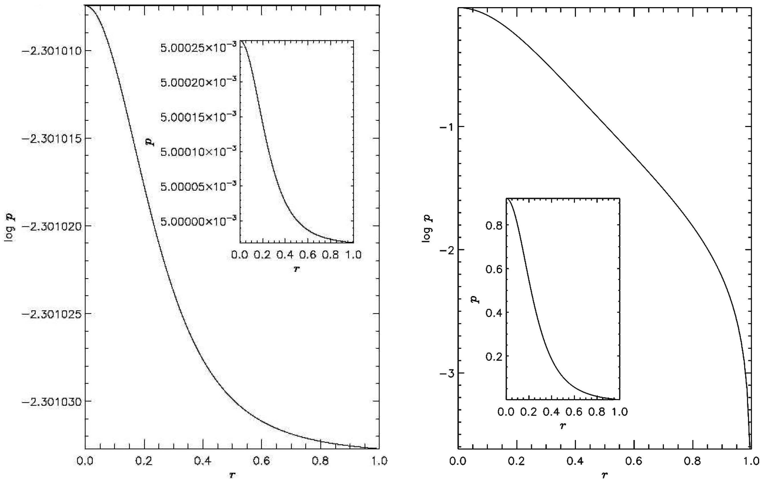
2.2. Transversal Equilibrium

Under the conditions established in the previous Section, the equation for the transversal equilibrium of the jet reduces to (see [16] and references therein):
d p * d r = ρ h * W 2 ( v ϕ ) 2 ( b ϕ ) 2 r .
In this equation, p * and h * stand for the total pressure and the specific enthalpy, including the contribution of the magnetic field
p * = p + b 2 2 ,
h * = 1 + ε + p / ρ + b 2 / ρ ,
where p is the gas pressure, ρ its density, and ε its specific internal energy. Quantities b μ ( μ = t , r , ϕ , z ) are the components of the four-vector representing the magnetic field in the fluid rest frame, and b 2 stands for b μ b μ , where summation over repeated indices is assumed (note that we are absorbing a factor of 4 π in the definition of the magnetic field). Quantities v i ( i = r , ϕ , z ) are the components of the fluid three-velocity in the laboratory frame, which are related to the flow Lorentz factor, W, according to:
W = 1 1 v i v i .
The following relations hold between the components of the magnetic field four-vector in the comoving frame, and the three-vector components B i measured in the laboratory frame:
b 0 = W B i v i , b i = B i W + b 0 v i .
The square of the modulus of the magnetic field can be written as
b 2 = B 2 W 2 + ( B i v i ) 2
with B 2 = B i B i .
Equation (4) establishes the transversal equilibrium between the total pressure gradient and the centrifugal force (first term on the right-hand side, r.h.s.), which tends to produce a positive gradient of the radial total pressure profile, and the magnetic tension (second term on the r.h.s), which in turn favours an increase of the total pressure towards the axis. Once the radial profiles of ρ, v ϕ , v z , B ϕ , and B z are fixed, we solve the resulting equation for the profile of the gas pressure, p, together with the boundary condition at the jet surface given by p * ( r = 1 ) = p a .
The models considered in the following subsections correspond to ρ j = 0 . 01 , v j z = 0 . 97 , R B ϕ , m = 0 . 37 , and p a = 0 . 1 .

2.2.1. Jets without Rotation

Figure 1 displays two representative equilibrium models of non-rotating jets. In the left panel, the toroidal magnetic field is small enough to produce an almost constant gas pressure profile inside the jet. In the case of the model displayed in the right panel, the magnetic tension makes the gas pressure drop three orders of magnitude across the jet, producing an equilibrium model with a central spine with high pressure (see inset panel).

2.2.2. Jets with Rotation

Two illustrative equilibrium models of differentially rotating jets ( v j , m ϕ = 0 . 2 , R v ϕ , m = 0 . 25 ) are shown in Figure 2. In the left panel, the gas pressure profile of the equilibrium model displays a deep minimum at r 0 . 25 due to the centrifugal force caused by the jet rotation. Models with larger azimuthal speeds and/or smaller azimuthal magnetic fields would cause the minimum pressure to reach negative values. In the case of the model shown in the right panel, the toroidal magnetic field in the inner region is large enough to keep the pressure high, despite the action of the centrifugal force.

3. Internal Structure of Axisymmetric, Overpressured Jets

In this Section, the kind of equilibrium profiles discussed in Section 2 are used as a boundary condition to inject the jets into a two-dimensional domain representing an ambient medium with a pressure mismatch. In their attempt to regain equilibrium, the jets undergo sideways motions, generating radial components of the flow velocity and the magnetic field that break the slab symmetry of the original jet model along the z axis.

3.1. Parameters

Now, the parameters describing the injection models are, on one hand, the jet density, ρ j , and the azhimutal and axial components of the jet flow velocity, v j ϕ , v j z , respectively. The magnetosonic Mach number ( M m s , j , see the definition in the Appendix of [17]) will be used to fix the average gas pressure in the beam. The toroidal and axial components of the magnetic field will be fixed through the jet magnetization (the ratio between the magnetic pressure and the gas pressure), β j = b j 2 / ( 2 p j ) , and the magnetic pitch angle, ϕ j = arctan ( B j ϕ / B j z ) . Finally, instead of the ambient pressure, we shall fix the overpressure factor, K. Both the relativistic magnetosonic Mach number and the overpressure factor govern the properties of internal conical shocks in overpressured magnetized jets in the same way as the corresponding quantities do in purely hydrodynamic jets.
Table 1 displays the values of the six parameters (namely ρ j , v j , K, M m s , j , β j , and ϕ j ) defining the models. Given the type of transversal equilibrium profiles considered in this work (obtained for specific profiles of the azimuthal magnetic field, as discussed in the previous section), K, M m s , j , β j , and ϕ j represent jet cross-section averages. All of the jet models have the same rest-mass density and flow velocity, and the same average magnetic pitch angle and overpressure factor (a value of the magnetic pitch angle of 45 is a compromise between toroidal and poloidal magnetic field dominated models. A study of the dependence of the jet’s main properties as a function of the magnetic field topology will be the subject of further investigation). On the contrary, the relativistic magnetosonic Mach number changes by a factor of five, and the magnetization by a factor of 20 among the different jet models. All the models have initial azimuthal speeds equal to zero. Table 1 also displays some derived parameters, such as the pressure mismatch at the jet surface, K 1 , the ambient pressure, p a , and the specific internal energy in the jet, ε j . The ambient pressure changes by more than two orders of magnitude, although its value is always small compared with the rest-mass energy density of the ambient medium. The values of the specific internal energy in the jet span three orders of magnitude, including cold as well as hot jet models. Finally, the transition between the jet and the ambient medium is smoothed by means of a shear layer of width Δ r s l by convolving the sharp jumps with the function sech ( r m ) , where m [ 4 , 16 ] . By introduzing this shear layer, the current sheet at the jet surface is removed, and the models are stabilized against pinch instabilities (see Section 3.4).
The parameters of the models are chosen to span a wide region in the M m s , j - 1 / ε j plane (see Figure 3). According to the type of energy flux that dominates, jet models can be classified as kinetically-dominated (those models dominated by the rest-mass energy ρ j > max ( ρ j ε j , b j 2 ) and Lorentz factor W j 1 ), internal energy-dominated (or hot jets, ρ j ε j > max ( ρ j , b j 2 ) ), and Poynting-flux-dominated ( b j 2 > max ( ρ j , ρ j ε j ) ). The plane displayed in Figure 3 has the virtue of placing these three types of models in well-separated regions.
Names are given to the models according to the following rule: two capital letters to indicate the two dominating energy types (“K” for kinetically dominated jets; “P” for Poynting-flux-dominated jets; “H” for hot jets) in order of prevalence, and two digits related to the Mach number of the jet flow.

3.2. Numerical Simulations

The jets are injected through a nozzle of radius unity into an axisymmetric cylindrical domain with ( r , z ) [ 0 , L r ] × [ 0 , L z ] , L r = 6 , and L z = 60 , 80 , 120 , depending on the spacing of the shocks in each model. The evolution of the flow in the domain is simulated with the RMHD code in 2D radial, axial, cylindrical coordinates with a resolution of 80 (40) cells per jet radius in the radial (axial) direction. In order to disturb the ambient medium as little as possible along the simulation, the domain ( r , z ) [ 0 , 1 ] × [ 0 , L z ] is initially filled with the analytical injection solution. Reflecting boundary conditions are set along the axis ( r = 0 , z > 0 ) and at the jet base outside the injection nozzle ( r > 1 , z = 0 ). Zero gradient conditions are set in the remaining boundaries.
The numerical RMHD code used in these simulations is a second-order, conservative, finite-volume code based on high-resolution shock-capturing techniques. An overview of the specific algorithms used in the code, and an analysis of its performance can be found in Appendices A and B, respectively, of [16].
The models, set up to be in equilibrium with an ambient pressure p a = K p a ( K > 1 ) are injected into an atmosphere with pressure p a . The new equilibrium states are set through a series of conical fast-magnetosonic shocks, the counterparts of the quasi-steady features in VLBI observations of jets (according to the present models), which are the subject of study in this section.

3.3. Overall Jet Structure

The steady jets corresponding to three representative cases of the models defined in Table 1 are shown in Figure 4, Figure 5 and Figure 6. Each figure contains panels displaying the distributions of rest-mass energy density and gas pressure (both in logarithmic scale), flow Lorentz factor (with the poloidal streamlines superimposed), and toroidal and axial magnetic field components (with the poloidal magnetic field lines superimposed on the axial magnetic field panel). Aside from these maps, another one displaying the azimuthal flow speed generated during the jet evolution is also shown. Some general conclusions can be extracted from the analysis of these figures:
(1)
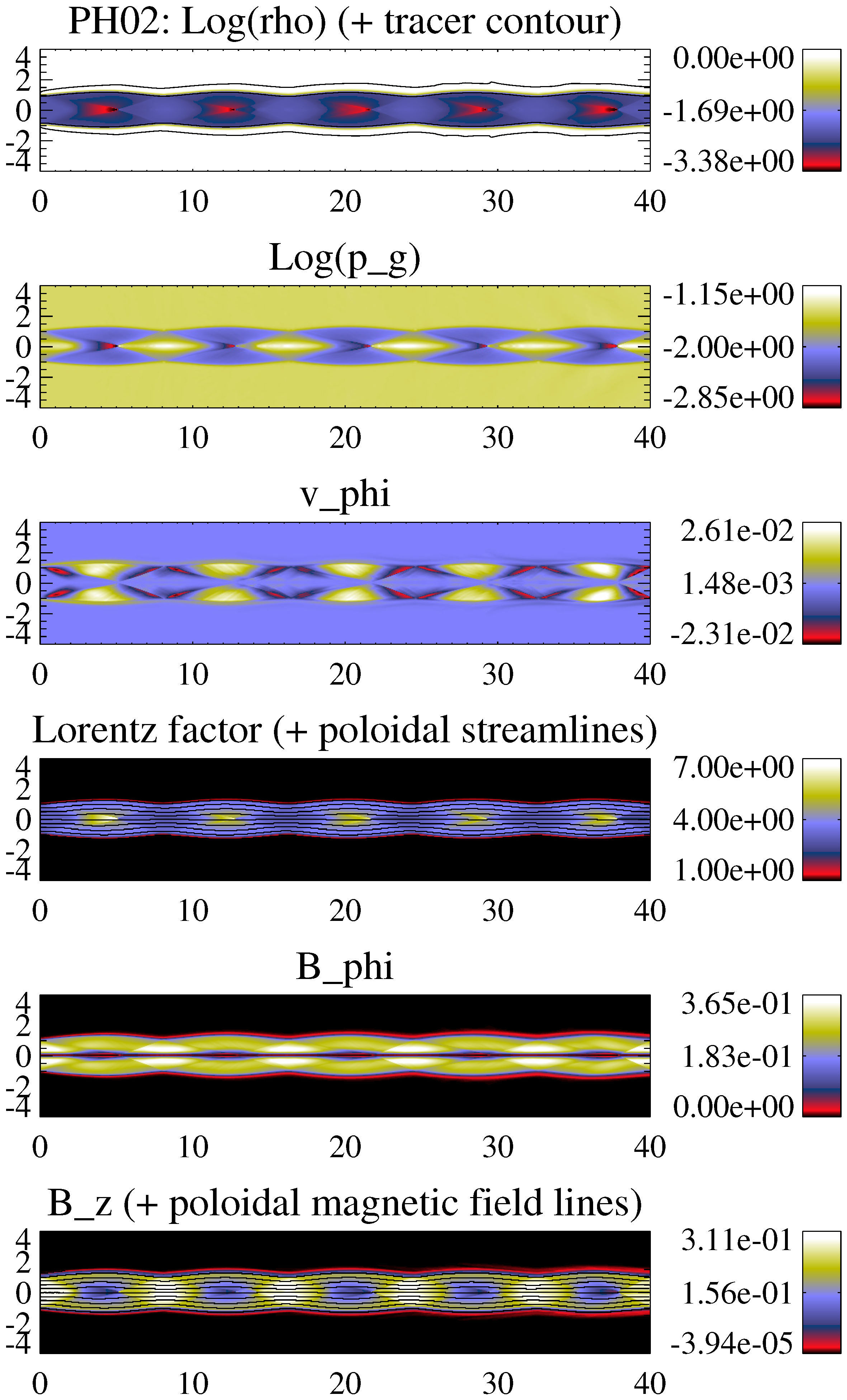
In all of the models, the equilibrium of the jet is established by a series of expansions and compressions of the jet flow against the ambient medium. Standing oblique shocks (recollimation shocks) associated with these jet oscillations can be distinguished in some cases, especially in hot models (PH02, see Figure 4; HP03, not shown) and, to a lesser extent, in colder, low magnetization models (KH06, KH10, not shown). The shock separation depends on the (magnetosonic) Mach number and the jet overpressure factor, whereas its strength depends on the jet’s internal energy density.
(2)
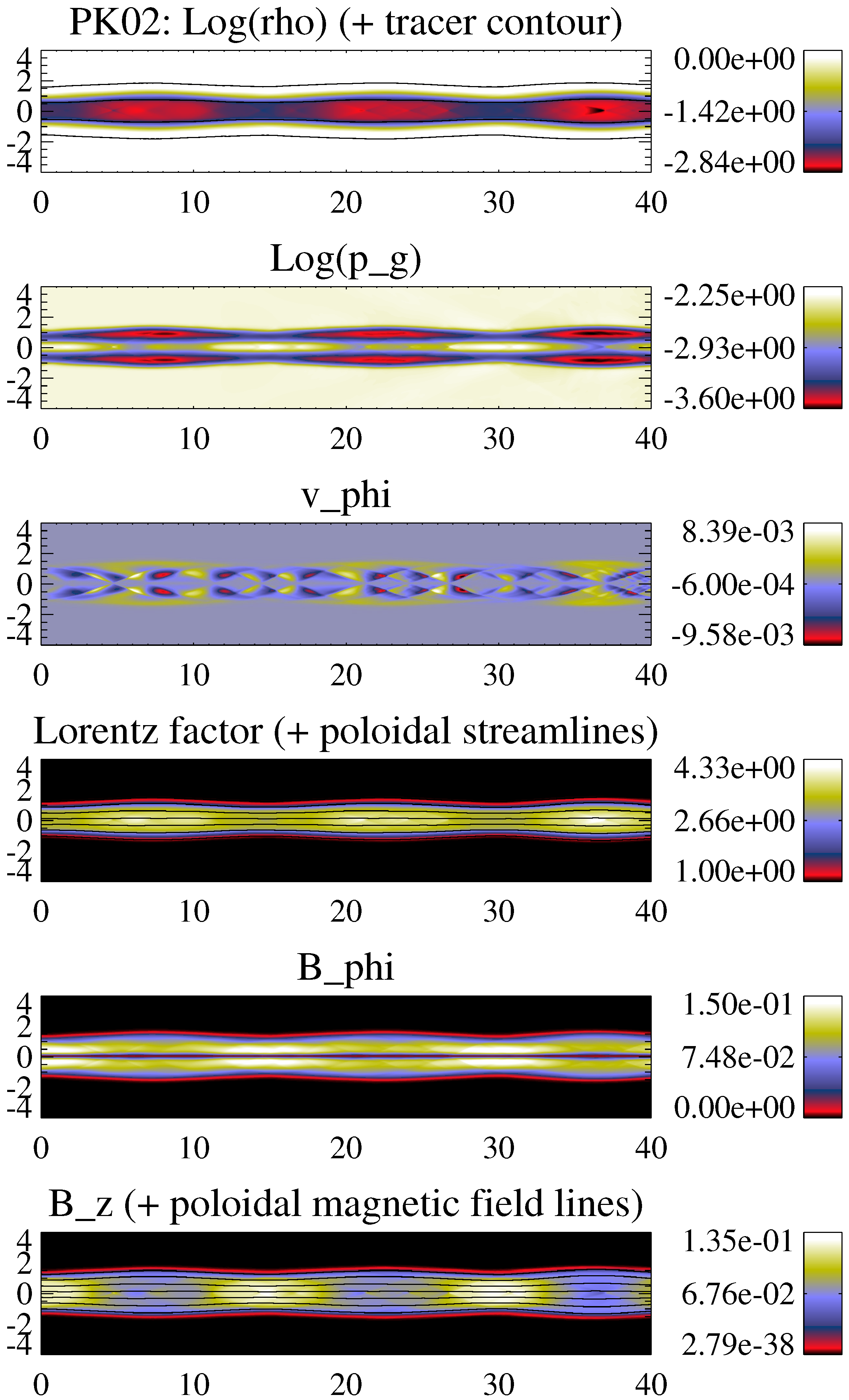
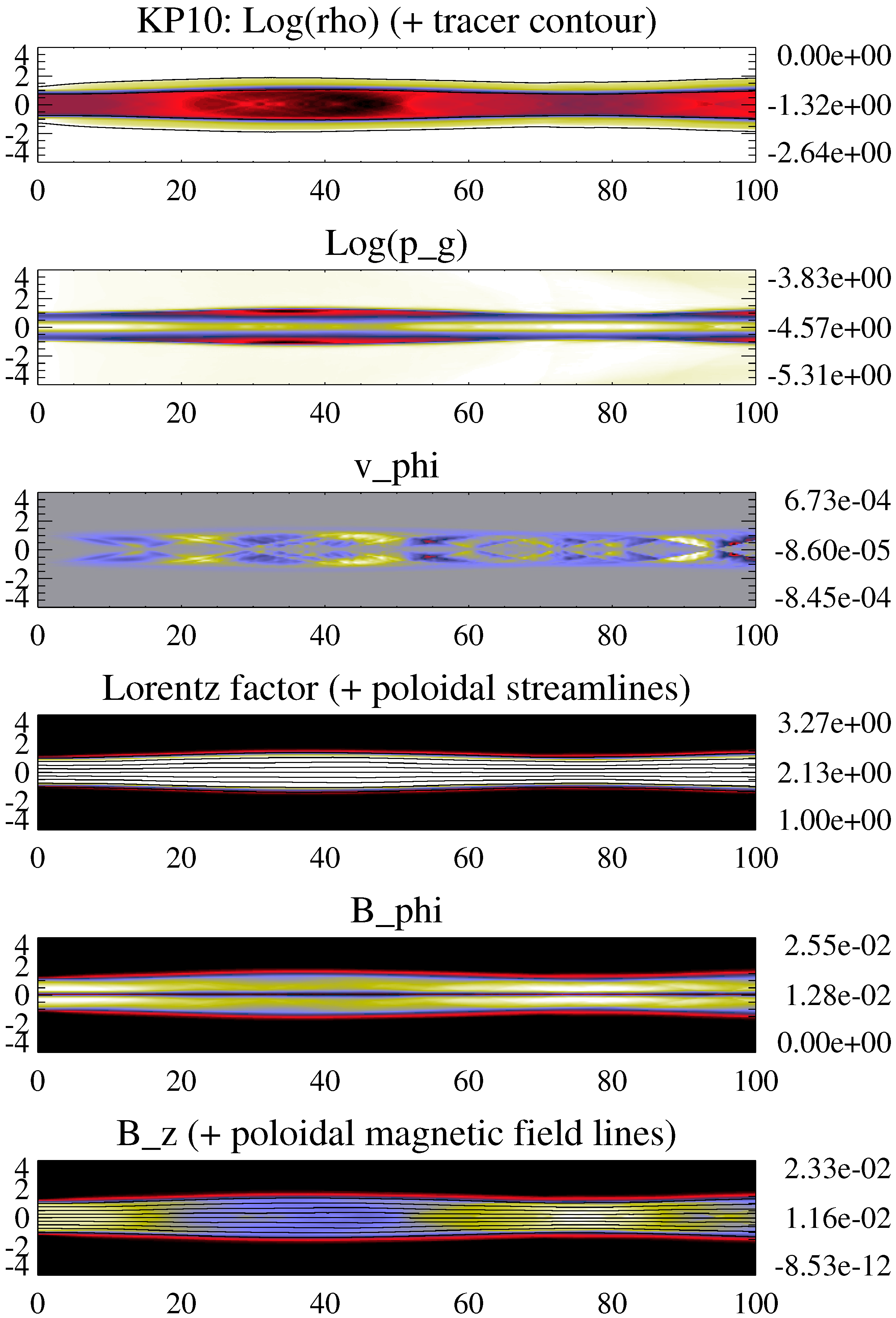
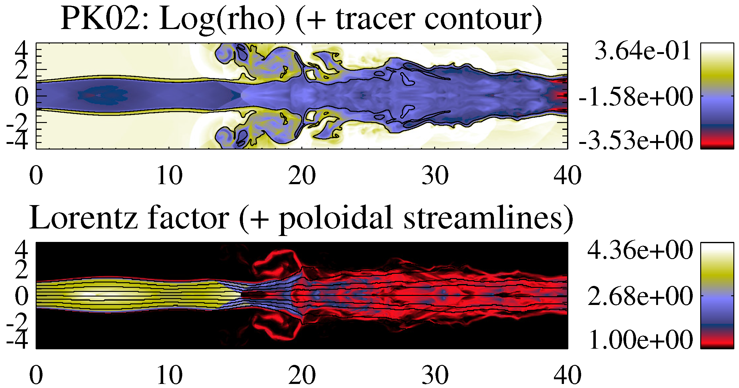
As a consequence of the profile of the magnetic pressure across the jet, and especially of the magnetic pinch exerted by the toroidal magnetic field, the gas pressure is not constant across the jet (see the discussion on the transversal structure of the jet models in Section 2). Models with large magnetizations (PK02, PK03, KP06, KP10) concentrate most of their internal energy in a thin hot spine around the axis (see the panels of gas pressure of models PK02 and KP10 in Figure 5 and Figure 6, respectively).
(3)
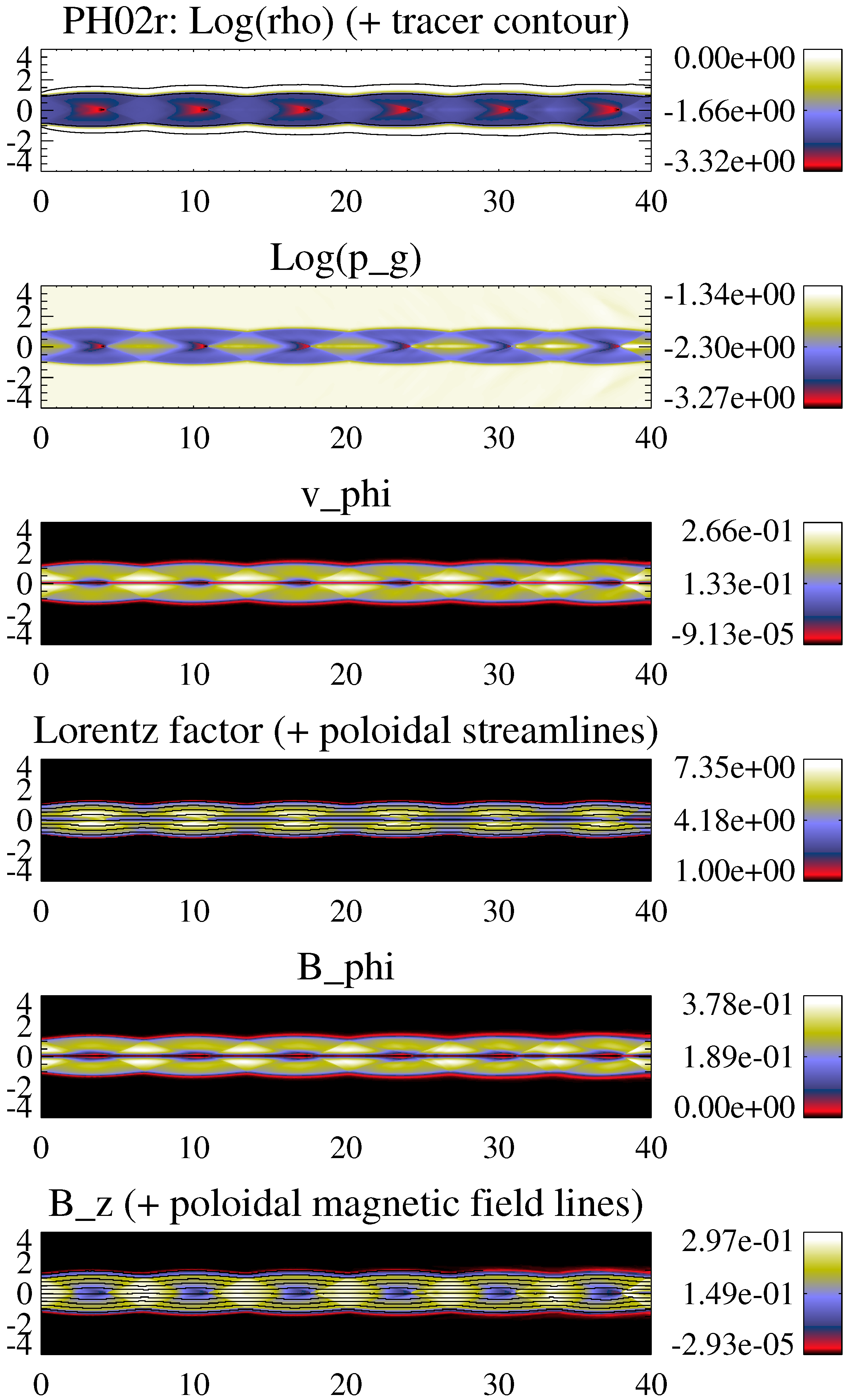
Despite the large difference in magnetization (a factor of 20), kinetically-dominated jet models KH10 and KP10 have very similar overall structure (jet oscillation, amplitude of variations, local jet opening angles, etc.), with the exception of the already mentioned central hot (in relative terms) spine in the KP10 jet. In these kinetically-dominated models, there is no significant internal nor magnetic energy to convert into kinetic, and the flow Lorentz factor is virtually constant in spite of the wide jet sideways oscillations (see Lorentz factor panel in Figure 6).
(4)
Although the jets are injected into the numerical domain with purely axial flow velocities, the development of radial components of the velocity and the magnetic field, and an axial dependence of the toroidal magnetic field—as a result of the transversal equilibrium mismatch between the injected jet and the ambient medium—produce a net toroidal force that causes the growth of non-zero azimuthal flow speeds. All of the models develop small azimuthal velocities (of the order of 2% of the speed of light or smaller). These speeds tend to be larger in models with larger maximum local opening angles (again, hot models and neighbours; compare azimuthal flow speed panels of models PH02 and KP10 in Figure 4 and Figure 6).

3.4. Effects of the Shear Layer on Poynting-Flux-Dominated Jets

Before settling into their final steady solutions, the overpressured jet models undergo a transient phase in which the flow suffers axially-symmetric sideways expansions and compressions. In some cases—remarkably, those corresponding to cold, Poynting-flux-dominated jets PK02 and PK03—the pinch exerted at some points of the jet axis during this transient phase (due to the coupling of the sideways oscillation caused by the jet overpressure with current driven instabilities, CDI; see, e.g., [18]) decelerates the flow to subsonic speeds and breaks the flow collimation beyond some axial distance (note, however, that since our simulations are axisymmetric, they are free of three-dimensional CDI, as the kink instability).
Numerical experiments have shown that the CDI growth rates are reduced in the case of magnetized flows with parallel magnetic fields or flows shrouded by (magnetized) winds [18,19,20]. Kim et al. [21] focussed on the stability of (non-relativistic) magnetized jets that carry no net electric current and do not have current sheets. The introduction of current-sheet-free magnetic fields significantly improves jet stability relative to unmagnetized jets or magnetized jets with current sheets at their surface. Moreover, the introduction of shear [22] also has a strongly stabilizing effect on various modes of jet instability. Unfortunately, no studies of jet stability for the case of sheared, magnetized, relativistic jets have been performed so far, but the aforementioned results from simulations of CDI development in the jet/wind scenario point in the same direction as for sheared, non-magnetized, relativistic jets [23]. On the other hand, our results based on simulations of sheared jets without current sheets at their surfaces extend (at least qualitatively) the conclusions of refs. [21,22] to the relativistic regime. Figure 7 shows a snapshot of model PK02 with a thinner shear layer ( Δ r s l 0 . 12 , instead of 0 . 49 ). In this case, the sideways expansion of the jet due to the injection into an underpressured ambient medium excites the growth of pinch instabilities, which cause the formation of a Mach disk at z 15 and the complete decollimation and deceleration of the flow beyond this point.

3.5. Effects of Flow Rotation

Figure 8 shows a snapshot of a jet similar to model PH02 (Figure 4), but injected with a rotation law as given by Equation (3), with v j , m ϕ = 0 . 25 and R v ϕ , m = 0 . 25 . The primary effect of the jet rotation is the redistribution of pressure across the jet under the action of the centrifugal force, as discussed in Section 2.2.2. In addition, (1) the spatial periodicity of the shock pattern changes by a ≈20%, and the shock angle changes accordingly; (2) due to the conservation of angular momentum and the transversal equilibrium, the flow keeps the rotation along the jet; (3) the Lorentz factor spreads across the jet instead of concentrating close to the jet symmetry axis.
The reduction of the spatial periodicity of the shock pattern with respect to the non-rotating case increases the shock angle and hence the posssibility for the flow to generate Mach disks. Despite this, no Mach disk is resolved in this simulation.

4. Conclusions

The internal structure of superfast magnetosonic overpressured jets has been analyzed. Despite its limitations, this study, partially presented in [17] and reported here, is the first attempt to identify the structural ingredients (including the properties of recollimation shocks) characterizing hot, Poynting-flux-dominated and kinetically-dominated, relativistic jets. Our study is of special relevance in the interpretation of parsec-scale AGN jets.

Acknowledgments

José-María Martí thanks the organizers José L. Gómez and Svetlana Jorstad for their kind invitation to participate in this meeting celebrating the immense contribution of Alan P. Marscher to the blazar research. The author is also indebted to José L. Gómez and M. Perucho for their collaboration in parts of this work. José-María Martí acknowledges financial support from the Spanish Ministerio de Economía y Competitividad (grants AYA2013-40979-P, and AYA2013-48226-C3-2-P) and from the local Valencian Government (Generalitat Valenciana, grant Prometeo-II/2014/069). Calculations were carried out using the Altix UV1000 supercomputer LluisVives at the University of Valencia.

Conflicts of Interest

The authors declare no conflict of interest.

References

  1. Blandford, R.D.; Payne, D.G. Hydromagnetic flows from accretion discs and the production of radio jets. Mon. Not. R. Astron. Soc. 1982, 199, 883–903. [Google Scholar] [CrossRef]
  2. Li, Z.-Y.; Chiueh, T.; Begelman, M.C. Electromagnetically driven relativistic jets: A class of self-similar solutions. Astrophys. J. 1992, 394, 459–471. [Google Scholar] [CrossRef]
  3. Blandford, R.D.; Znajek, R.L. Electromagnetic extraction of energy from Kerr black holes. Mon. Not. R. Astron. Soc. 1977, 179, 433–456. [Google Scholar] [CrossRef]
  4. Daly, R.A.; Marscher, A.P. The gasdynamics of compact relativistic jets. Astrophys. J. 1988, 334, 539–551. [Google Scholar] [CrossRef]
  5. Marscher, A.P.; Jorstad, S.G.; D’Arcangelo, F.D.; Smith, P.S.; Williams, G.G.; Larionov, V.M.; Oh, H.; Olmstead, A.R.; Aller, M.F.; Aller, H.D.; et al. The inner jet of an active galactic nucleus as revealed by a radio-to-γ-ray outburst. Nature 2008, 452, 966–969. [Google Scholar] [CrossRef] [PubMed]
  6. Marscher, A.P.; Jorstad, S.G.; Larionov, V.M.; Aller, M.F.; Aller, H.D.; Lähteenmäki, A.; Agudo, I.; Smith, P.S.; Gurwell, M.; Hagen-Thorn, V.A.; et al. Probing the inner jet of the quasar PKS 1510-089 with multi-waveband monitoring during strong gamma-ray activity. Astrophys. J. Lett. 2010, 710, L126–L131. [Google Scholar] [CrossRef]
  7. Gómez, J.L.; Lobanov, A.P.; Bruni, G.; Kovalev, Y.Y.; Marscher, A.P.; Jorstad, S.G.; Mizuno, Y.; Bach, U.; Sokolovsky, K.V.; Anderson, J.M.; et al. Probing the innermost regions of AGN jets and their magnetic fields with RadioAstron. I. Imaging BL Lacertae at 21 μ as resolution. Astrophys. J. 2016, 817, 96. [Google Scholar] [CrossRef]
  8. Boccardi, B.; Krichbaum, T.P.; Bach, U.; Mertens, F.; Ros, E.; Alef, W.; Zensus, J.A. The stratified two-sided jet in Cygnus A. Astron. Astrophys. 2016, 585, A33. [Google Scholar] [CrossRef]
  9. Mertens, F.; Lobanov, A.P.; Walker, R.C.; Hardee, P.E. Kinematics of the jet in M87 on scales of 100–1000 Schwarzschild radii. Astron. Astrophys. 2016, in press. [Google Scholar] [CrossRef]
  10. Lind, K.R.; Payne, D.G.; Meier, D.L.; Blandford, R.D. Numerical simulations of magnetized jets. Astrophys. J. 1989, 344, 89–103. [Google Scholar] [CrossRef]
  11. Komissarov, S.S. A Godunov-type scheme for relativistic magnetohydrodynamics. Mon. Not. R. Astron. Soc. 1999, 303, 343–366. [Google Scholar] [CrossRef]
  12. Leismann, T.; Antón, L.; Aloy, M.A.; Müller, E.; Martí, J.M.; Miralles, J.A.; Ibáñez, J.M. Relativistic MHD simulations of extragalactic jets. Astron. Astrophys. 2005, 436, 503–526. [Google Scholar] [CrossRef]
  13. Lyubarsky, Y.E. Kink instability of relativistic force-free jets. Mon. Not. R. Astron. Soc. 1999, 308, 1006–1010. [Google Scholar] [CrossRef]
  14. Mizuno, Y.; Lyubarsky, Y.; Nishikawa, K.-I.; Hardee, P.E. Three-dimensional relativistic magnetohydrodynamic simulations of current-driven instability. I. Instability of a static column. Astrophys. J. 2009, 700, 684–693. [Google Scholar] [CrossRef]
  15. Mizuno, Y.; Lyubarsky, Y.; Nishikawa, K.-I.; Hardee, P.E. Three-dimensional relativistic magnetohydrodynamic simulations of current-driven instability. III. Rotating relativistic jets. Astrophys. J. 2012, 757, 16. [Google Scholar] [CrossRef]
  16. Martí, J.M. The structure of steady, relativistic, magnetized jets with rotation. Mon. Not. R. Astron. Soc. 2015, 452, 3106–3123. [Google Scholar] [CrossRef]
  17. Martí, J.M.; Perucho, M.; Gómez, J.L. The internal structure of overpressured, magnetized, relativistic jets. Astrophys. J. 2016, in press. [Google Scholar]
  18. Hardee, P.E. The stability of astrophysical jets. In Jets at All Scales (IAU S275) (Proceedings of the International Astronomical Union Symposia and Colloquia); Romero, G.E., Sunyaev, R.A., Belloni, T., Eds.; Cambridge University Press: Cambridge, UK, 2011; p. 41. [Google Scholar]
  19. Hardee, P.E.; Rosen, A. Dynamics and structure of three-dimensional trans-Alfvénic jets. II. The effect of density and winds. Astrophys. J. 2002, 576, 204–221. [Google Scholar] [CrossRef]
  20. Mizuno, Y.; Hardee, P.E.; Nishikawa, K.-I. Three-dimensional relativistic magnetohydrodynamic simulations of magnetized spine-sheath relativistic jets. Astrophys. J. Lett. 2007, 662, 835–850. [Google Scholar] [CrossRef]
  21. Kim, J.; Balsara, D.S.; Lyutikov, M.; Komissarov, S.S.; George, D.; Siddireddy, P.K. On the linear stability of magnetized jets without current sheets—Non-relativistic case. Mon. Not. R. Astron. Soc. 2015, 450, 982–997. [Google Scholar] [CrossRef]
  22. Kim, J.; Balsara, D.S.; Lyutikov, M.; Komissarov, S.S. On the linear stability of sheared and magnetized jets without current sheets—Non-relativistic case. Mon. Not. R. Astron. Soc. 2016, 461, 728–741. [Google Scholar] [CrossRef]
  23. Perucho, M.; Martí, J.M.; Hanasz, M. Nonlinear stability of relativistic sheared planar jets. Astron. Astrophys. 2005, 443, 863–881. [Google Scholar] [CrossRef]
Figure 1. Pressure equilibrium profiles for two representative jet models without rotation. Model parameters: ρ j = 0 . 01 , v j z = 0 . 97 , B j , m ϕ = 1 . 58 × 10 3 (left panel), 2 . 81 (right panel), R B ϕ , m = 0 . 37 , B j z = 0 . 436 (left panel), 4 . 36 × 10 2 (right panel), p a = 0 . 1 .
Galaxies 04 00051 g001
Figure 2. Pressure equilibrium profiles for two representative jet models with the same rotation profile (rigidly rotating inner jet core and a Keplerian sheath). Model parameters: ρ j = 0 . 01 , v j , m ϕ = 0 . 20 , R v ϕ , m = 0 . 25 , v j z = 0 . 97 , B j , m ϕ = 0 . 151 (left panel), 0 . 443 (right panel), R B ϕ , m = 0 . 37 , B j z = 0 . 396 (left panel), 4 . 41 × 10 1 (right panel), p a = 0 . 1 .
Galaxies 04 00051 g002
Figure 3. Jet classes in the M m s , j 1 / ε j plane according to the dominant energy type, for given jet flow velocity, v j = 0 . 95 . Drawn are lines of constant magnetization (0, 1, 10, 100, 1000). Kinetically-dominated jets, Poynting-flux-dominated jets, and hot jets are placed in the diagram with the help of three (red) lines, corresponding to models with ρ j = ρ j ε j , b j 2 = ρ j ε j , b j 2 = ρ j . Pure hydrodynamic models are placed on the β j = 0 line, which bounds a forbidden region (in violet) corresponding to unphysical models with negative magnetic energies. Superimposed: Distribution on the M m s , j 1 / ε j diagram of the models considered in this work.
Galaxies 04 00051 g003
Figure 4. Steady structure of the Poynting-flux-dominated, hot jet PH02. From top to bottom are distributions of rest-mass density, gas pressure, azimuthal flow velocity, flow Lorentz factor, and toroidal and axial magnetic field components once the steady state has been settled. Poloidal flow and magnetic field lines are superimposed onto the Lorentz factor and axial magnetic field panels, respectively. Two contour lines for jet mass fraction values 0.005 and 0.995 are overplotted on the density panel.
Galaxies 04 00051 g004
Figure 5. Steady structure of the Poynting-flux-dominated jet PK02. Panel distribution as in Figure 4.
Galaxies 04 00051 g005
Figure 6. Steady structure of the kinetically-dominated, highly magnetized jet KP10. Panel distribution as in Figure 4. The axial scale has been compressed by a factor of two with respect to the radial one.
Galaxies 04 00051 g006
Figure 7. Structure of the Poynting-flux-dominated jet PK02 with a thinner shear layer. Top panel: distribution of rest-mass density with two contour lines for jet mass fraction values 0.005 and 0.995. Bottom panel: flow Lorentz factor distribution with poloidal flow lines overplotted.
Galaxies 04 00051 g007
Figure 8. Steady structure of the Poynting-flux-dominated, hot jet PH02 with rotation. Panel distribution as in Figure 4.
Galaxies 04 00051 g008
Table 1. Parameters defining the overpressured jet models.
Model ρ j [ ρ a ] K v j [ c ] M m s , j β j ϕ j [ ] Δ r s l a [ R j ] ε j [ c 2 ] K 1 b p a [ ρ a c 2 ]
PH02 5 × 10 3 2 0 . 95 2 . 0 00 2 . 77 0 45 . 0 0.12 10 . 0 0000 1 . 87 3 . 31 × 10 2
PK02 5 × 10 3 2 0 . 95 2 . 0 00 10 . 0 000 45 . 0 0.49 0 . 458 0 1 . 84 4 . 20 × 10 3
HP03 5 × 10 3 2 0 . 95 3 . 5 00 0 . 454 45 . 0 0.12 10 . 0 0000 1 . 94 1 . 21 × 10 2
PK03 5 × 10 3 2 0 . 95 3 . 5 00 10 . 0 000 45 . 0 0.49 0 . 117 0 1 . 84 1 . 08 × 10 3
KH06 5 × 10 3 2 0 . 95 6 . 0 00 0 . 5 00 45 . 0 0.49 0 . 468 0 1 . 94 5 . 85 × 10 4
KP06 5 × 10 3 2 0 . 95 6 . 0 00 10 . 0 000 45 . 0 0.320.0317 1 . 84 2 . 90 × 10 4
KH10 5 × 10 3 2 0 . 95 10 . 0 00 0 . 5 00 45 . 0 0.24 0 . 133 0 1 . 94 1 . 66 × 10 4
KP10 5 × 10 3 2 0 . 95 10 . 0 00 10 . 0 000 45 . 0 0.240.0132 1 . 84 1 . 21 × 10 4
a Δ r s l is the width of the shear layer defined as the radial section of the jet where the function defining the transition, sech ( r m ) , is between 0.1 and 0.9, corresponding to jet mass fractions between 0.1 and 0.9. b K 1 stands for the total (gas plus magnetic) overpressure factor at the jet surface (see text).

