
Tribofilms Forming in Oil-Lubricated Contacts

Fraunhofer Institute for Mechanics of Materials IWM, MikroTribologie Centrum, Joseph-von-Fraunhofer Str. 7, 76327 Pfinztal, Germany
*
Author to whom correspondence should be addressed.
†
Current address: Department for Corrosion and Tribology SINTEF Materials and Chemistry, Richard Birkelandsvei 2B, PO box 4760 Sluppen, N-7465 Trondheim, Norway
Lubricants 2016, 4(3), 27; https://doi.org/10.3390/lubricants4030027
Submission received: 7 May 2016
/
Revised: 28 June 2016
/
Accepted: 7 July 2016
/
Published: 14 July 2016
(This article belongs to the Special Issue Tribofilms and Solid Lubrication)
Abstract
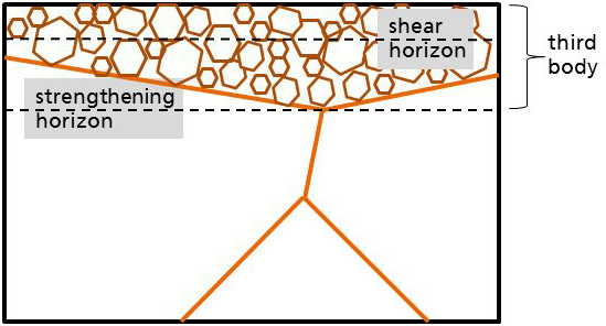
:The subject of the present paper is the characterization of third bodies of run-in systems. By means of continuous friction and wear measurement, lubricated steel-steel and steel-aluminum contacts were evaluated. Microstructure, chemical composition and response of the materials to shear were analyzed by XPS/AES and focused ion beam technique. After a proper running-in, both systems developed a third body. The third body differs significantly from the base materials. In addition to adapted microstructure and near-surface chemistry, the third body exhibited a substructure characterized by a near-surface zone that accommodates shear and a second, deeper region that ensures strengthening.
1. Introduction
As Dienwiebel et al. showed for a lubricated chromium-cast iron contact with a contact pressure in the MPa range, that the question whether the film is on top or underneath can be answered by analyzing the energy consumption during film formation—very often during running-in—and by observing the changes of surface, microstructure and chemical composition of the near-surface as function of time [1]. For MPa systems in the initial stage of their running-in and highly-loaded contacts (GPa) like gears, the materials tend to develop protective films, commonly containing Zn, P and S from extreme pressure additives. When the running-in was accomplished, the MPa systems developed a tribofilm in the near-surface of both friction bodies, whereas the GPa systems kept the tribofilm on top. Since the GPa contacts always show a small percentage of slip, film formation underneath the surface can be observed as well [2].
During the running-in, energy in the form of heat and plastic deformation is deposited in the materials. The involved materials respond by changes in topography (dissipative structures [3], material transfer or film formation), changes in near-surface microstructure, phase transformation and modified chemical composition. Godet coined the term third body in 1984 [4]. Later on, terms like tribologically transformed layer, reaction layer or tribomutation appeared, causing a great deal of confusion in the community.
Targeting the materials response during running-in, Rigney et al. investigated the involved mechanisms leading to changes in near-surface structure and to the introduction of foreign elements as result of intermixing processes [3,5,6,7]. The third body is the prerequisite for ultra-low wear rates and small coefficients of friction. In [8] we elucidated on the mechanisms that convey a tribological system into this state. The bottom line was that the amount of friction power density at the beginning of the running-in is of crucial importance to the achievement of superb tribological properties, as mentioned above. These properties are connected to the quality of the tribofilm underneath the surface. Initial overstressing as well as understressing of the mechanical system are detrimental, since too much power density leads to a wear rate that prevents the third body from growing. Understressing, on the other hand, results in a situation that does not provide enough power to ignite the necessary mechano-chemical reactions to form the third body. Only an appropriate amount of power opens a running-in corridor and brings the system into the desired state by inducing the right degree of plastic flow, mechanical intermixing and mechano-chemical reactions. At the beginning of third body formation, the metal has to be locally charged above its yield strength to deform the material homogeneously, as reported by Rogers [9].
The focus of this paper is the interplay between microstructural and chemical properties of the third body. For the running-in characterization of two different tribological systems (steel vs. steel and steel vs. aluminum), focused ion beam technique was applied to analyze the development in grain size. With photoelectron spectroscopy chemical changes due to mechanical intermixing were made visible. Finally, a shallow implantation of gallium atoms allowed the quantification of shear in the near-surface of the friction bodies. The comparison of the two systems with different oils and materials can help finding properties of third bodies in lubricated contacts that are, in a first approximation and for the shown systems, independent on tribomaterials and lubricants It will be shown that a third body develops in both systems and possesses a substructure that is responsible for friction and wear.
2. Materials and Methods
Two sets of samples—steel versus steel and steel versus aluminum—were tribologically characterized under lubricated conditions using a pin-on-disk tribometer. After tribometry, the samples were analyzed with respect to their microstructure, chemical composition and response to shear. The focus was laid on near-surface phenomena.
2.1. Materials
2.1.1. Steel Disk (56NiCrMoV7) versus Steel Pin (C86)
56NiCrMoV7 exhibits a homogeneous, martensitic microstructure with less than 2% of residual austenite and minor carbidic precipitates at the grain boundaries, see Figure 1a. The disks were cut, ground and annealed and have a diameter of 75 mm. After annealing the disks were lapped. The microhardness was 6–8 GPa for an indentation depth up to 300 nm. The composition of the disk is presented in Table 1.
The pins were made of C86, received a surface treatment by lapping and have a diameter of 5 mm. The pin C86 (AISI 1086) contains the following chemical constituents (at%): C: 0.35–1; Si: 0.1–0.3; Mn: 0.5–1.2; P: <0.035; S: <0.035; Cu: <0.2. The pin-on-disk tribometer tests were carried out with lubrication using a polyalphaolefine base oil with a dynamic viscosity of 25.7 mPa·s at a temperature of . To achieve a sufficiently good running-in, the tests were run at a contact pressure of 20 MPa at 0.1 m/s sliding velocity. This parameter set was chosen because pre-tests with continuous friction and wear recordings indicated a stable running-in behavior for these conditions.
2.1.2. Aluminum Disk (AlSi9Cu3) versus Steel Pin (100Cr6)
The base alloy for the disks showed a fine fibrous network of silicon [10,11]. The composition is shown in Table 2.
The disks were machined with a Wiper cutting tool and subsequently subjected to a heat treatment (solution heat treatment at 480 C for 5 h followed by artificial aging at 180 C for 4 h). The heat treatment resulted in a coarse globular Si phase, see Figure 1b. The microhardness was measured to be 2.5–3 GPa for an indentation depth up to 1000 nm. The disks have a diameter of 50 mm. The pins with a diameter of 5 mm were polished using a belt machining process yielding an average roughness of 16 nm. The chemical composition of the machined surface was found to be 5 at% Cr and 15 at% C in carbides with the balance being Fe. The oil used for all experiments was fully-formulated synthetic engine oil Castrol Edge FST 5W30 (BP, London, UK) at a temperature of 70 C. For the tribological, a contact pressure of 45 MPa and a sliding velocity of 2 m/s were applied. All data are summarized in Table 3.
2.2. Methods
2.2.1. Tribometry
The oil circuit of the tribometer (BASALT SST, TETRA GmbH, Ilmenau, Germany) was filled with 2.5 L. Using a nozzle, oil was directly supplied to the disk. To achieve a flat contact between pin and disk, the pin holder allowed a self-regulating adjustment. The geometric area of contact during the whole experiment is approx. 18.8 mm2. The pins have a slightly tapered edge to prevent undesired cutting into the disk. Friction and wear of the pin were monitored continuously. The pins were irradiated for radionuclide technique (RNT). Both types of pins contained chromium, thus allowing the generation of Cr-51 nuclides by low-energy neutron radiation. Due to wear, debris containing the nuclide get into the oil and a highly-sensible detector counts gamma pulses when the oil passes the sensor head (Zyklotron AG, Eggenstein-Leopoldshafen, Germany). After calibration micrograms of wear can be detected in the oil circuit which corresponds to a wear rate of a few nanometers per hour. Details of the method were described by Scherge et al. [12].
Friction experiments have been carried out in mixed lubrication, as can be seen from the continuously rising wear signal as measured by RNT. If the friction experiment would be in the elasto-hydrodynamic regime, there wouldn’t be a wear signal from the RNT, and if the experiment would be in the boundary lubrication regime, the friction coefficient would be much higher.
2.2.2. Structural Analysis
The preparation of cross sections and the imaging with electron microscopy were accomplished using a dual beam instrument with electron and focused ion beam (FIB) (Helios Nanolab 650, FEI, Hillsboro, OR, USA). Prior to cross sectioning, areas of interest were covered with a protective platinum-rich layer by ion beam assisted deposition.
2.2.3. Chemical Analysis
Chemical composition of the surfaces after machining as well as in the wear track was measured by X-ray photoelectron spectroscopy (XPS). A PHI 5000 Versaprobe System (Physical Electronics, Chanhassen, MN, USA) was used with 15 keV monochromatic Al-Kα-X-rays and an energy resolution of 0.2 eV. An area of m contributed to the photoelectron signal. Depth profiling was done by sputtering with argon ions. Auger electron spectroscopy (AES) was measured with a PHI 680 Xi Auger Nanoprobe (Physical Electronics) equipped with a field emission gun. Spectra were excited with 10 keV and 20 nA. Argon ions were used for material removal for depth profiling. The sputter rate was determined by means of a silicon oxide reference, yielding comparable values with an error in the depth values of about 10%.
2.2.4. Shear Analysis
For the analysis of the system with respect to shear, near-surface gallium markers were introduced to the aluminum disk. The preparation was performed with the same machine as for structural analysis, see above. A rectangular area (m) was exposed to 30 keV Ga ion bombardment in deposition mode with a milling current of 200 pA for 6000 s. The area was subjected later to shear during the friction experiment. Attention was particularly paid to the frontier between aluminum with gallium markers and without. The experiment with the Ga marker was conducted at 25 MPa and a disk sliding distance of 1200 m which corresponds to an effective sliding distance of the pin of 45 m. Details of the experiment are described in [13].
3. Results
3.1. Friction and Wear Analysis
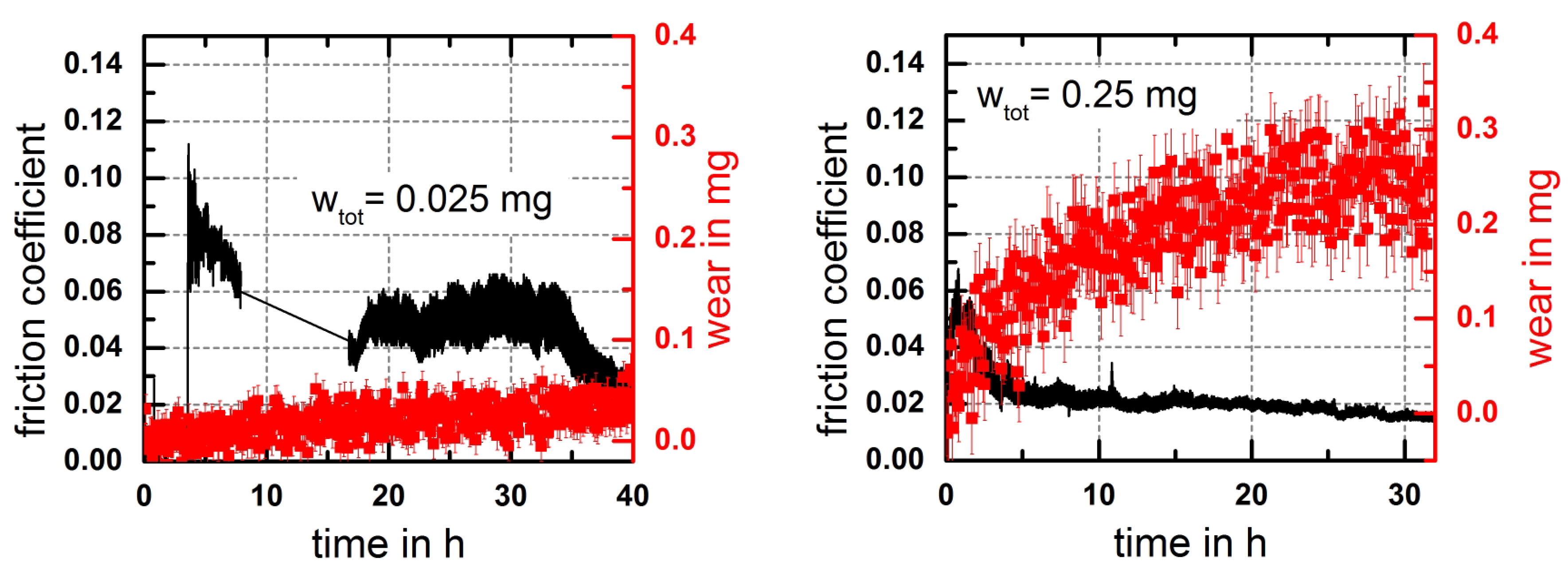
Friction and wear were recorded continuously. The steel-steel system started with a coefficient of friction of 0.1 and showed good running-in behavior leading to a final coefficient of 0.02. The steel-aluminum systems showed a distinct running-in behavior as well with a lower initial coefficient of friction of 0.04 that decreased in the course of the experiment to 0.02. The friction and wear signals are shown in Figure 2. For the RNT-experiments and their repetitions a constant slope of the wear signal in the last part of the running-in allowed the calculation of the wear rate. The scatter of the wear signal was caused by the random nature of radioactive decay. Wear of the disks was determined by white light interferometry after the test. The linear wear rate—the quotient of wear track depth and runtime—was in the same range as for the pins. Whereas the wear rate of the steel-steel systems was below the limit of resolution (≈1 nm/h), the steel-aluminum system developed a wear rate of 4 nm/h.
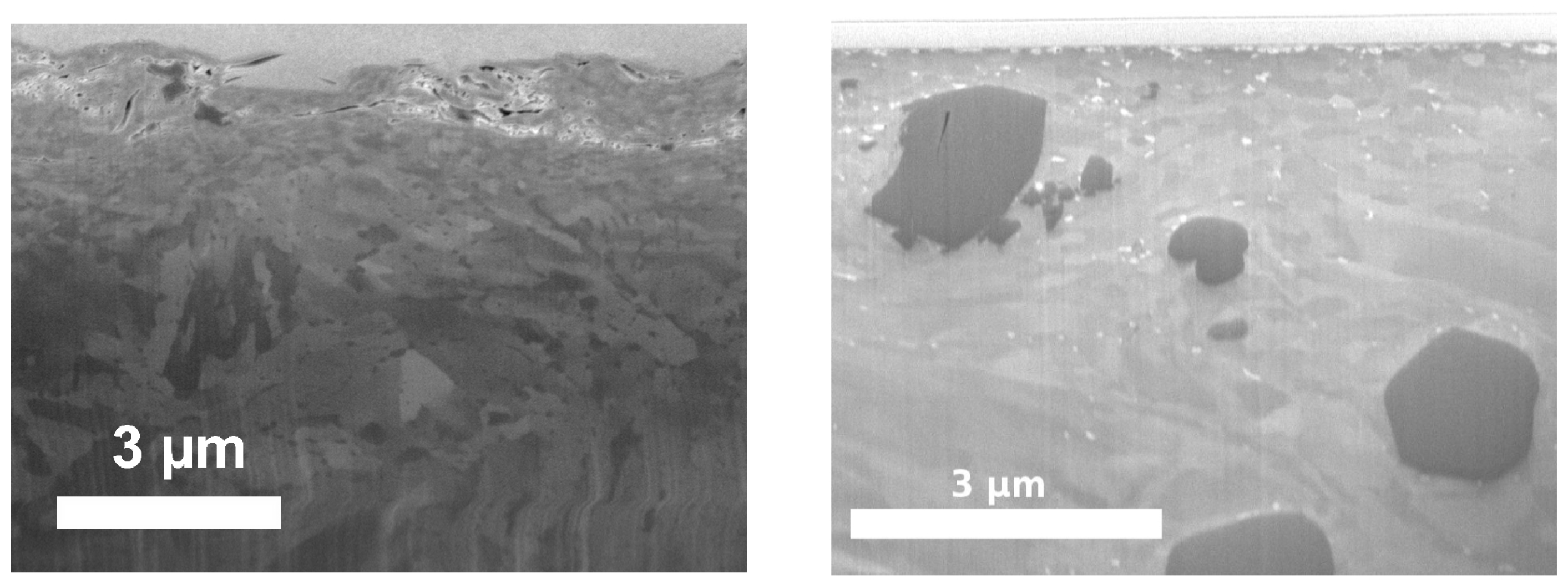
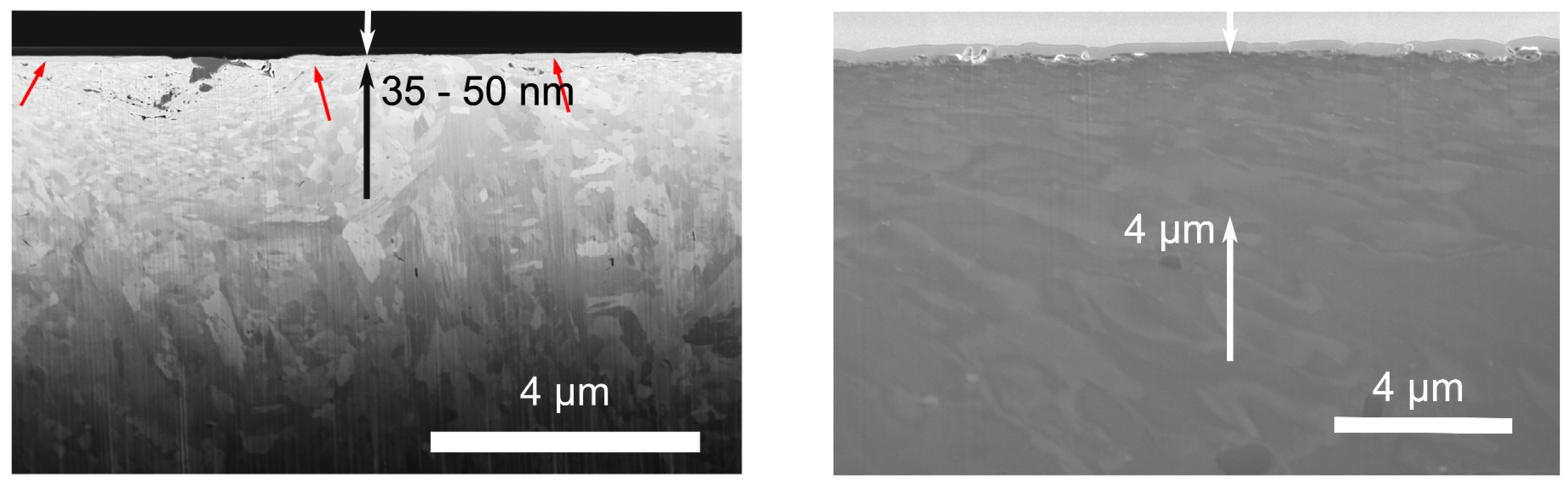
3.2. Microstructural Analysis
In order to observe changes in microstructure caused by the running-in, cross sections with focused ion beam were prepared. The SEM images of the cross sections are shown in Figure 3. The cross sections were placed in sliding direction. The differences in near-surface microstructures of steel and aluminum compared with the state of the bulk are obvious. The steel disk developed areas of nanocrystalline structure with a thickness indicated by arrows in Figure 3. The aluminum disk showed a compact submicrocrystalline near-surface structure with a depth up to m. In contrast to aluminum, the steel disk showed nanocrystalline areas with a sharp interface between nanocrystals and bulk. The near-surface grains are deformed in sliding direction and have a longitudinal shape.
3.3. Chemical Analysis
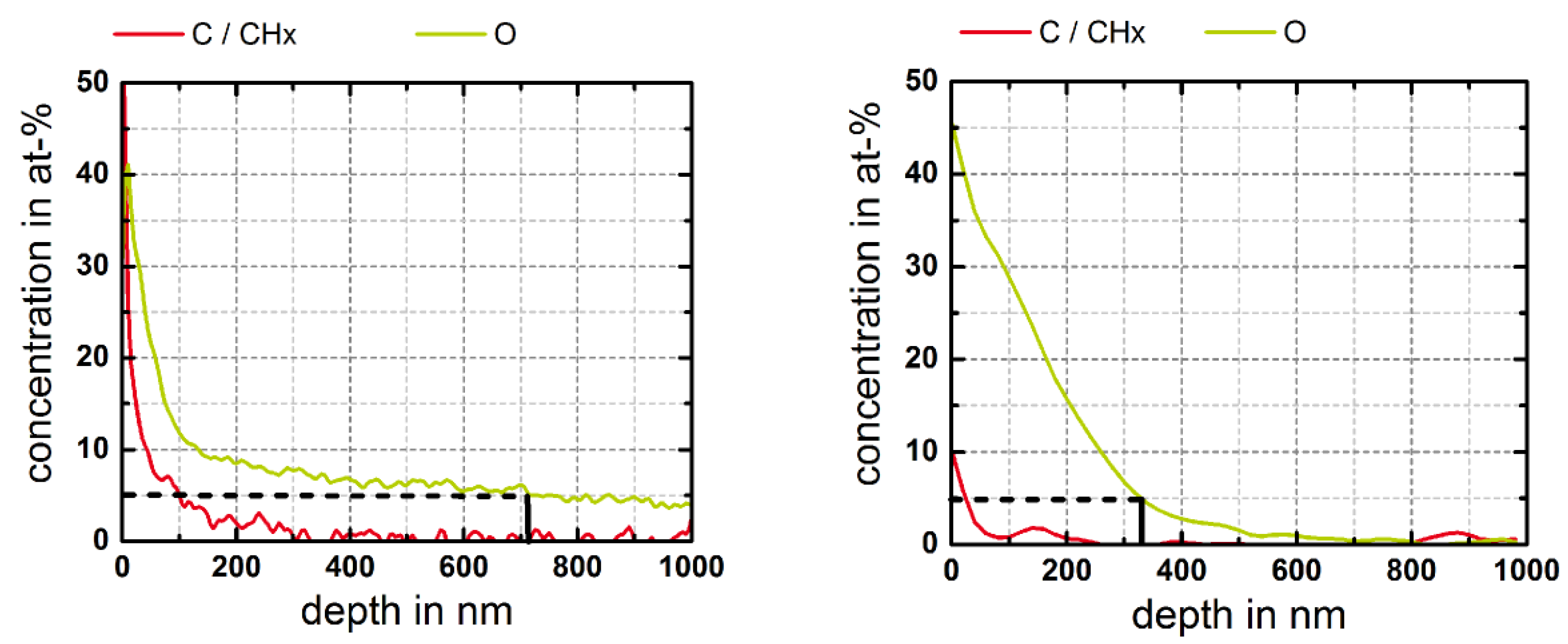
XPS depth profiles were recorded to analyze the near-surface region and to show signs of mechanical intermixing without interpretation of tribo-chemical reactions. The measurements were conducted on the worn disks. The general depth profiles showed foreign elements from the oil (C and CH), anti-wear additives (S, P, Zn) and Ca originating from a detergent. For the sake of clarity and due to the fact that the experiments with the steel disks were caried out with an additive-free oil, the depth profiles shown in Figure 4 only contain O and C/CH. All stressed disks showed a significantly higher oxygen concentrations in the near-surface compared with the intake of carbon and CH groups. In order to extract typical depth values from the profiles, the point were the atomic concentration reached 5% was taken, indicated by insets in Figure 4.
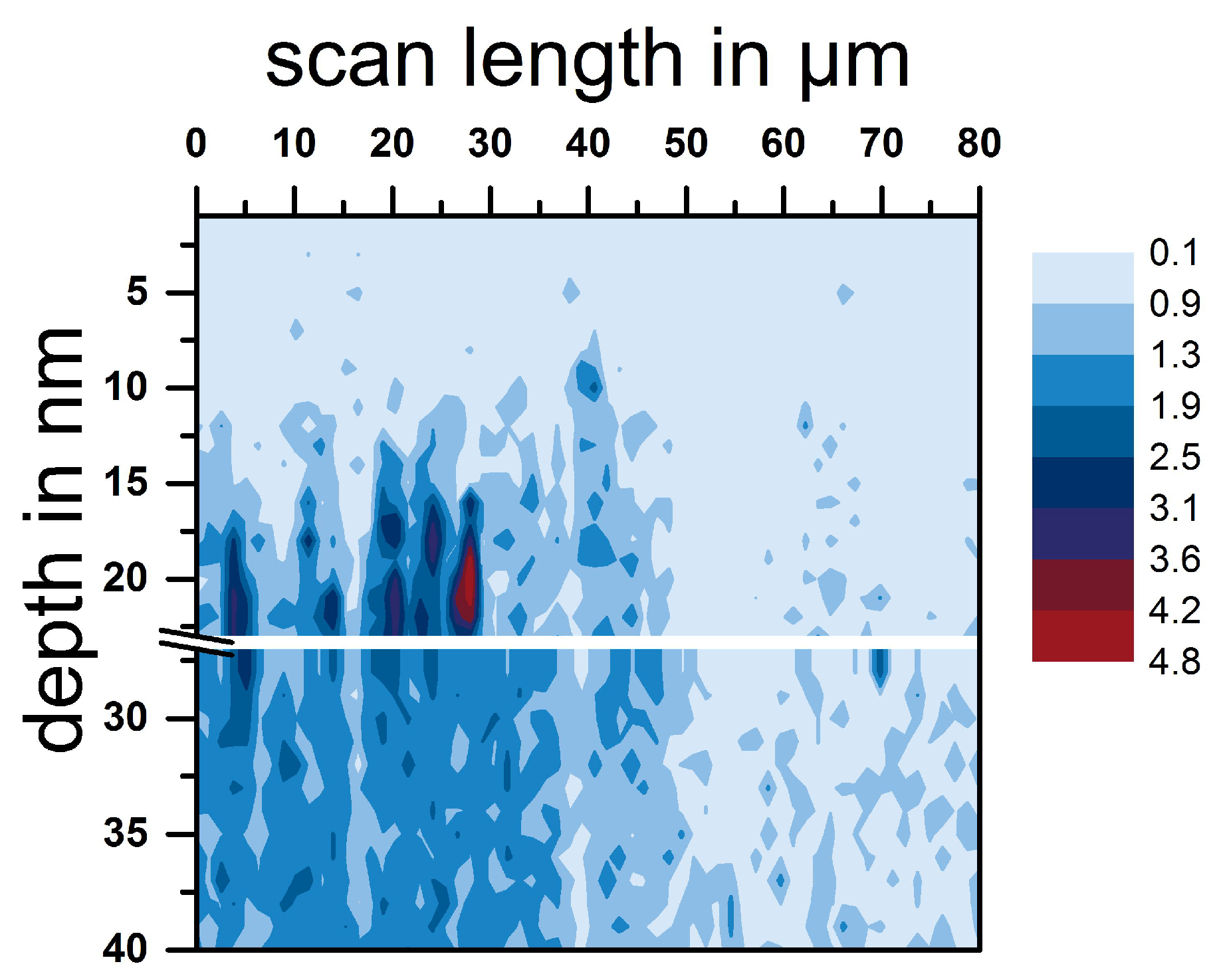
3.4. Shear Analysis (Al Disk Only)
With the gallium-implanted disk a sliding test was performed to analyze the initial stages of shear. After the run an AES linescan was placed alongside the wear track. The scan length of m was long enough to cover the frontier between the gallium-implanted area and base material at m. The linescan was expanded to a depth profile by taking additional linescans after repeated removals of 3 nm of material. The total depth of the profile was 130 nm. Gallium was found beginning at a depth of 30 nm. In addition to the implanted area, gallium was found next to it as well. The detected concentrations were above noise level. Traces of gallium were found more than m away from the implanted area. This is significantly more than the lateral uncertainty of the Ga implantation field of m, see Figure 5.
4. Discussion
Friction and wear of both systems showed clear evidence of a proper running-in. A definition of running-in was introduced in [14]: A proper running-in is achieved when the tribological system quickly develops low friction and small wear rate at high system stability and low sensitivity. Stability refers to the effect that the system quickly passes the running-in and adopts a constant wear rate. Tribological systems can have several stable states. Sensitivity reflects the property of the system that friction and wear show negligible response to changes of the boundary conditions such as oil temperature, load or speed changes. The discussion to explain the tribofilm formation—here the formation of the third body—is based on the model proposed by Godet and Berthier. In addition, to consider the energy flows with respect to the running-in corridor, a balance is introduced:
The total power of friction can be received by multiplication of coefficient of friction, normal force and sliding velocity v. At the right side of the equation the resulting energy flows are shown. The total power of friction triggers a heat flow , the generation of wear and the change of material involved in third body interactions . In [15] it was shown for gray cast iron versus chromium that the amount of energy that is transformed into heat ranges between 70% and 80%. Only a fraction—often less than 1%—contributes to wear. As a consequence, between 20% and 30% of the energy is consumed by third body interactions. Due to different bulk properties (hardness, Youngs modulus, yield stress) of steel and aluminum, differences in should be visible in the properties of the third body, i.e., near-surface microstructure and chemical composition.
Changes in microstructure between steel and aluminum and between initial and worn state were demonstrated by focused ion beam analysis. Both systems show a fine-grained near-surface region. However, the nanocrystalline area on the aluminum disk was roughly ten times thicker than the one on the steel disk. This effect seems to be caused by the lower hardness of the aluminum alloy which is more sensitive to the impact of contact pressure and cyclic creep [16].
XPS depth profiles were used as a measure of intermixing. Due to plastic flow adsorbed species gradually become part of the near-surface. The XPS depth profiles of CH show for both disks that shear was located close to the surface in a range between 25 nm and 100 nm. The mechanical intermixing process during the initial stages of running-in could be illustrated by the marker experiment as well. In contrast, O showed a significantly deeper penetration into the base materials, which cannot be explained solely by intermixing. Quinn and Sulivan reported on an FeO layer that reduced friction, however, delaminated at a certain thickness [17]. The leading mechanism was oxidation, supported by shear and elevated temperatures. The production of heat—as described by the flash temperature concept [18]—is mainly controlled by friction power density and thermal conductivity of the metal. Aluminum is known to grow a dense oxide layer, protecting the underlying material from further oxidation. On the contrary, Fe oxidation is not constrained by an oxide film formation. For that reason, the oxygen concentration reaches deeper into the material.
Gallium ion markers were introduced to image the displacement of material at the near-surface, i.e., directly at the third body interface between both solids. After tribological stressing no gallium ions were present up to a depth of 30 nm. In addition, traces of gallium were found up to m away from the area where they were originally placed. This implies that mechanical intermixing involves lateral mass transfer from one location of the friction body to another, the introduction of foreign elements, transfer and incorporation of mass originating from the counter body and the re-incorporation of wear particles. The depth of 30 nm correlates very well with the depth of CH intake and underlines that shear was accomodated close to the surface. Shear is crucial to the model of Bowden-Tabor (friction force = shear coefficient × real contact area). The decrease in friction during proper running-in is based on the formation of the third body, on its part connected with decreasing shear coefficient. The newly-formed material of the third body has a smaller shear coefficient than the base material. The achievement of constant friction and wear rate suggests that the third body gradually moves into first and second body with a velocity equal to the wear rate. This process finally ceases when the systems fails due to fatigue. All findings will be summarized in Figure 6.
5. Conclusions
The following conclusions can be drawn:
- The third body is a tribofilm that is formed underneath the surface and extends into both friction bodies.
- The third body shows a dinstinctively altered topography, microstructure and chemical composition than the base materials.
- The third body possesses a substructure. The accomodation of shear takes place close to the inner surface and is characterized by the depth of intermixed CH groups.
- The depth of introduced oxygen depends on heat generation in the contact and the ability of the materials to grow a dense oxide.
Acknowledgments
The authors would like to thank M. Haesche and M. Häuser (Fraunhofer IFAM) for casting and T. Schmidt (Fraunhofer IWU) for the machining of the disks. Thanks are also due to E. Nold (Fraunhofer IWM) for XPS measurements. We acknowledge the support of the German Science Foundation (SPP 1551).
Author Contributions
M.S. conceived most of the experiments which were designed and performed by A.B. and D.L. The paper was written by M.S.
Conflicts of Interest
The authors declare no conflict of interest.
References
- Dienwiebel, M.; Poehlmann, K. Nanoscale Evolution of Sliding Metal Surfaces During Running-in. Tribol. Lett. 2007, 27, 255–260. [Google Scholar] [CrossRef]
- Reichelt, M.; Gunst, U.; Wolf, T.; Mayer, J.; Arlinghaus, H.; Gold, P. Nanoindentation, TEM and ToF-SIMS studies of the tribological layer system of cylindrical roller thrust bearings lubricated with different oil additive formulations. Wear 2010, 268, 1205–1213. [Google Scholar] [CrossRef]
- Scherge, M.; Shakhvorostov, D.; Poehlmann, K. Fundamental wear mechanism of metals. Wear 2003, 255, 395–400. [Google Scholar] [CrossRef]
- Godet, M. The third-body approach: A mechanical view of wear. Wear 1984, 100, 437–452. [Google Scholar] [CrossRef]
- Rigney, D.A.; Karthikeyan, S. The Evolution of Tribomaterial During Sliding: A Brief Introduction. Tribol. Lett. 2010, 39, 3–7. [Google Scholar] [CrossRef]
- Rigney, D. Transfer, mixing and associated chemical and mechanical processes during the sliding of ductile materials. Wear 2000, 245, 1–9. [Google Scholar] [CrossRef]
- Fischer, A. Subsurface microstructural alterations during sliding wear of biomedical metals. Modelling and experimental results. Comput. Mater. Sci. 2009, 46, 586–590. [Google Scholar] [CrossRef]
- Scherge, M.; Linsler, D.; Schlarb, T. The running-in corridor of lubricated metal-metal contacts. Wear 2015, 342, 60–64. [Google Scholar] [CrossRef]
- Rogers, H. Adiabatic plastic deformation. Ann. Rev. Mater. Sci. 1979, 9, 283–311. [Google Scholar] [CrossRef]
- Lasagni, F.; Lasagni, A.; Marks, E.; Holzapfel, C.; Muecklich, F.; Degischer, H. Three-dimensional characterization of as-cast and solution-treated AlSi12(Sr) alloys by high-resolution FIB tomography. Acta Mater. 2007, 55, 3875–3882. [Google Scholar] [CrossRef]
- Timpel, M.; Wanderka, N.; Schlesiger, R.; Yamamoto, T.; Isheim, D.; Schmitz, G.; Matsumura, S.; Banhart, J. SrAlSi co-segregated regions in eutectic Si phase of Sr-modified Al-10Si alloy. Ultramicroscopy 2013, 132, 216–221. [Google Scholar] [CrossRef] [PubMed]
- Scherge, M.; Poehlmann, K.; Gerve, A. Wear measurement using radionuclide-technique (RNT). Wear 2003, 254, 801–817. [Google Scholar] [CrossRef]
- Linsler, D.; Schlarb, T.; Weingaertner, T.; Scherge, M. Influence of subsurface microstructure on the running-in of an AlSi alloy. Wear 2015, 332, 926–931. [Google Scholar] [CrossRef]
- Brink, A.; Lichtenberg, K.; Scherge, M. Influencing the tibological performance by different initial microstructures and adjusting stressing levels during the running-in. Wear 2016. submitted. [Google Scholar]
- Shakhvorostov, D.; Poehlmann, K.; Scherge, M. An energetic approach to friction, wear and temperature. Wear 2004, 257, 124–130. [Google Scholar] [CrossRef]
- Fischer, A.; Weiss, S.; Wimmer, M. The tribological difference between biomedical steels and CoCrMo-alloys. J. Mech. Behav. Biomed. Mater. 2012, 9, 50–62. [Google Scholar] [CrossRef] [PubMed]
- Quinn, T.; Rowson, D.; Sullivan, J. Application of the oxidational theory of mild wear to the sliding wear of low alloy steel. Wear 1980, 65, 1–20. [Google Scholar] [CrossRef]
- Kuhlmann-Wilsdorf, D. Demystifying Flash Temperatures I. Analytical Expressions Based on a Simple Model. Mater. Sci. Eng. 1987, 93, 107–117. [Google Scholar] [CrossRef]
Figure 1.
(Left): Microstructure of the steel disk; (Right): Microstructure of the aluminum disk.

Figure 2.
Friction and wear behavior of steel (left) and aluminum disk (right). Due to temporary connection problems a part of the friction signal is missing.
Figure 2.
Friction and wear behavior of steel (left) and aluminum disk (right). Due to temporary connection problems a part of the friction signal is missing.

Figure 3.
Microstructure after running-in. (Left): Steel disk. (Right): Aluminum disk.

Figure 4.
Depth profiles of O and C/CH. (Left): Steel disk; (Right): Aluminum disk.

Figure 5.
Shear-induced displacement of Gallium markers [13].
Figure 5.
Shear-induced displacement of Gallium markers [13].

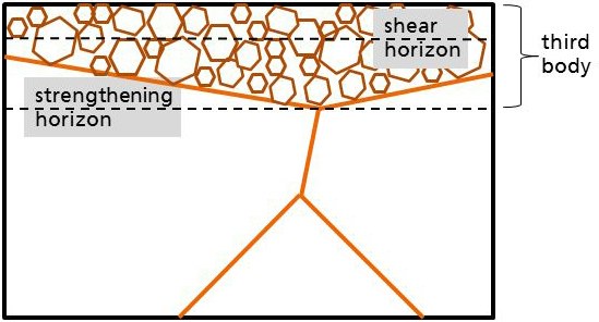
Figure 6.
Scheme of the third body as a grain-refined layer, subdividing in a shear and a strengthening horizon.
Figure 6.
Scheme of the third body as a grain-refined layer, subdividing in a shear and a strengthening horizon.


| Element | C | Si | Mn | P | S | Cr | Ni | Mo | V |
|---|---|---|---|---|---|---|---|---|---|
| Conc. in wt% | 0.5–0.6 | 0.1–0.4 | 0.65–0.95 | <0.03 | <0.03 | 0.1–1.2 | 1.5–1.8 | 0.45–0.55 | 0.07–0.12 |
| Element | Si | Cu | Fe | Zn | Mg | Mn, Pb, Ti | Sr | Al |
|---|---|---|---|---|---|---|---|---|
| Conc. in wt% | 10.6 | 2.5 | 0.9 | 0.8 | 0.2 | <0.2 | 200 ppm | balance |
| Steel Disk | Pin | Al Disk | Pin | |
|---|---|---|---|---|
| material | 56NiCrMoV7 | C86 | AlSi9Cu3 | N/A 100Cr6 |
| microhardness | 7–8 GPa | N/A | 2.5–3 GPa | N/A |
| austenitizing temperature | 850 C | N/A | N/A | N/A |
| annealing temperature | 630 C | N/A | 480 C | N/A |
| 150 nm | 10 nm | 75 nm | 16 nm |
© 2016 by the authors; licensee MDPI, Basel, Switzerland. This article is an open access article distributed under the terms and conditions of the Creative Commons Attribution (CC-BY) license (http://creativecommons.org/licenses/by/4.0/).
Share and Cite
MDPI and ACS Style
Scherge, M.; Brink, A.; Linsler, D. Tribofilms Forming in Oil-Lubricated Contacts. Lubricants 2016, 4, 27. https://doi.org/10.3390/lubricants4030027
AMA Style
Scherge M, Brink A, Linsler D. Tribofilms Forming in Oil-Lubricated Contacts. Lubricants. 2016; 4(3):27. https://doi.org/10.3390/lubricants4030027
Chicago/Turabian StyleScherge, Matthias, Angelika Brink, and Dominic Linsler. 2016. "Tribofilms Forming in Oil-Lubricated Contacts" Lubricants 4, no. 3: 27. https://doi.org/10.3390/lubricants4030027
Note that from the first issue of 2016, this journal uses article numbers instead of page numbers. See further details here.