
Rotordynamic and Friction Loss Measurements on a High Speed Laval Rotor Supported by Floating Ring Bearings


Abstract
:1. Introduction
2. Test Setup
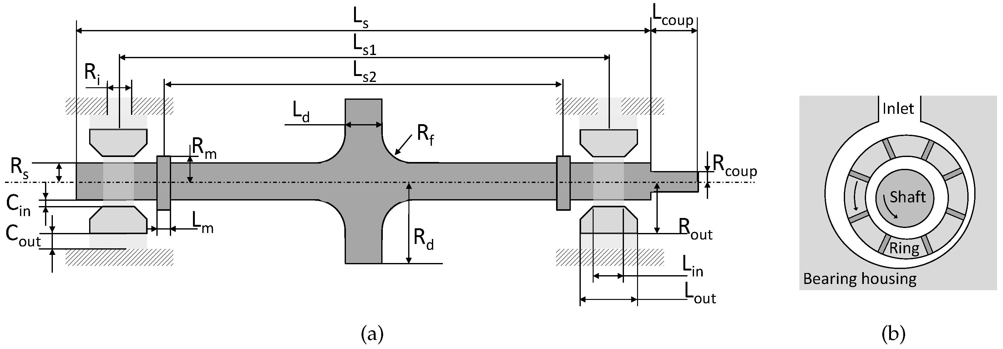
2.1. Rotor
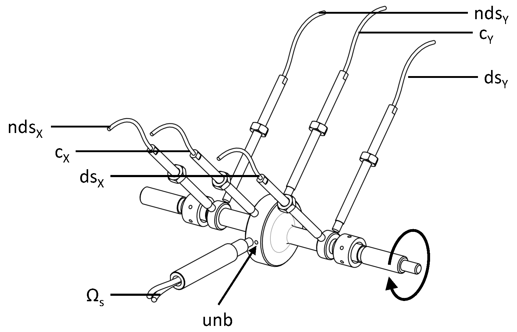
2.2. Sensor Configuration
2.3. Lubrication System and Temperature Control
2.4. Oil
2.5. Measurement Sequence
3. Results: Rotordynamic Response
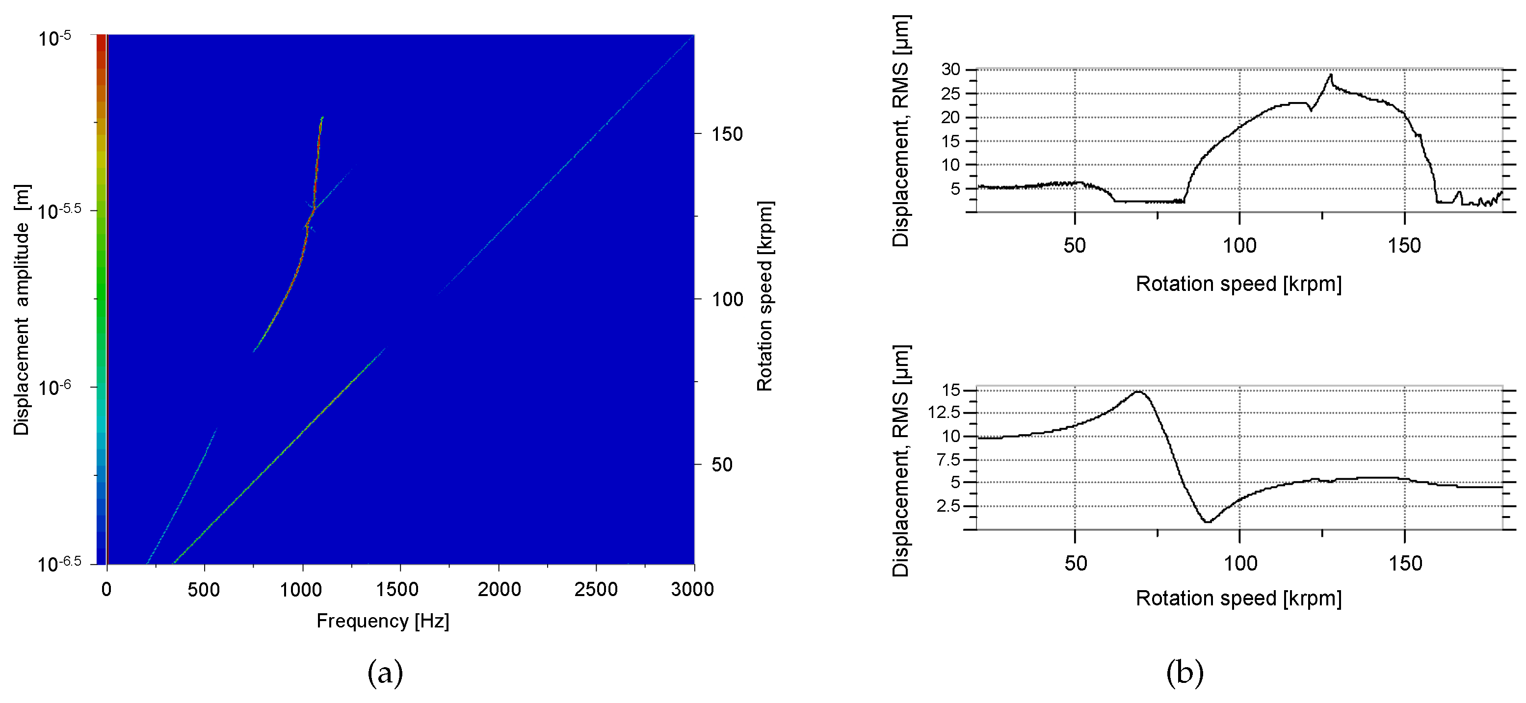
3.1. Rotordynamic Response at Standard Operating Conditions
- The oil inlet pressure is set at 2 bar.
- The oil inlet temperature is set at 310 K.
- The bearing housing temperature is set at 310 K .
- The rotor unbalance is set at 100 mg·mm.
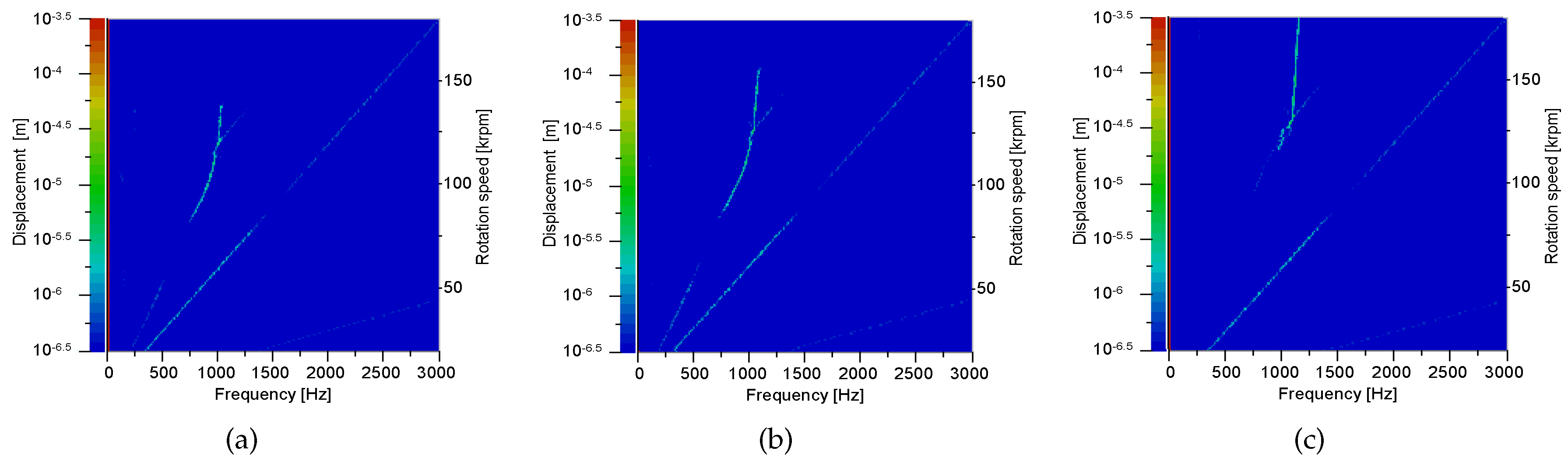
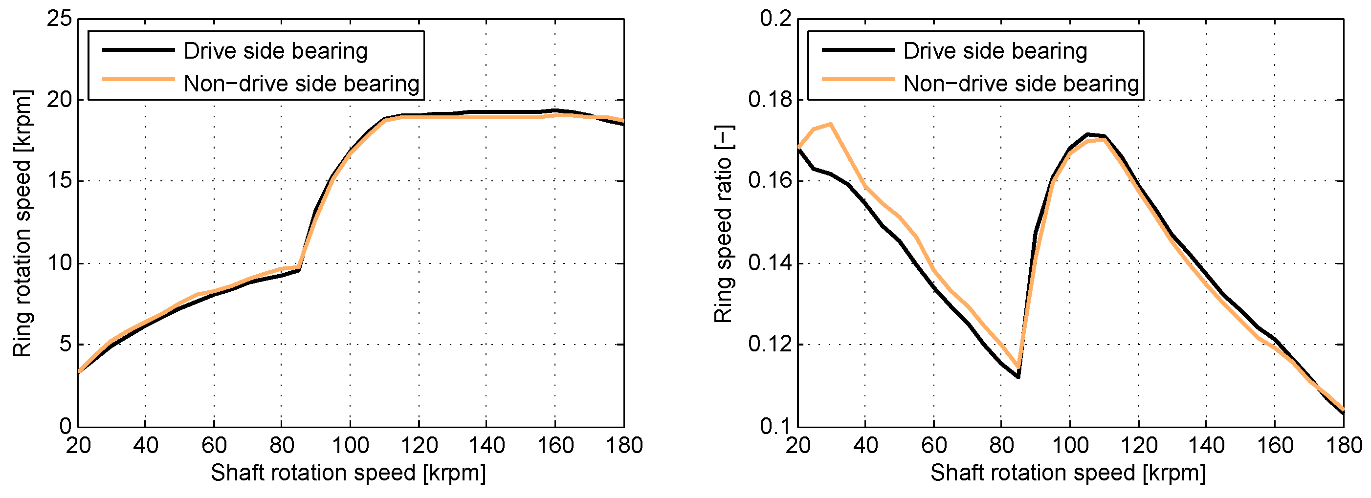
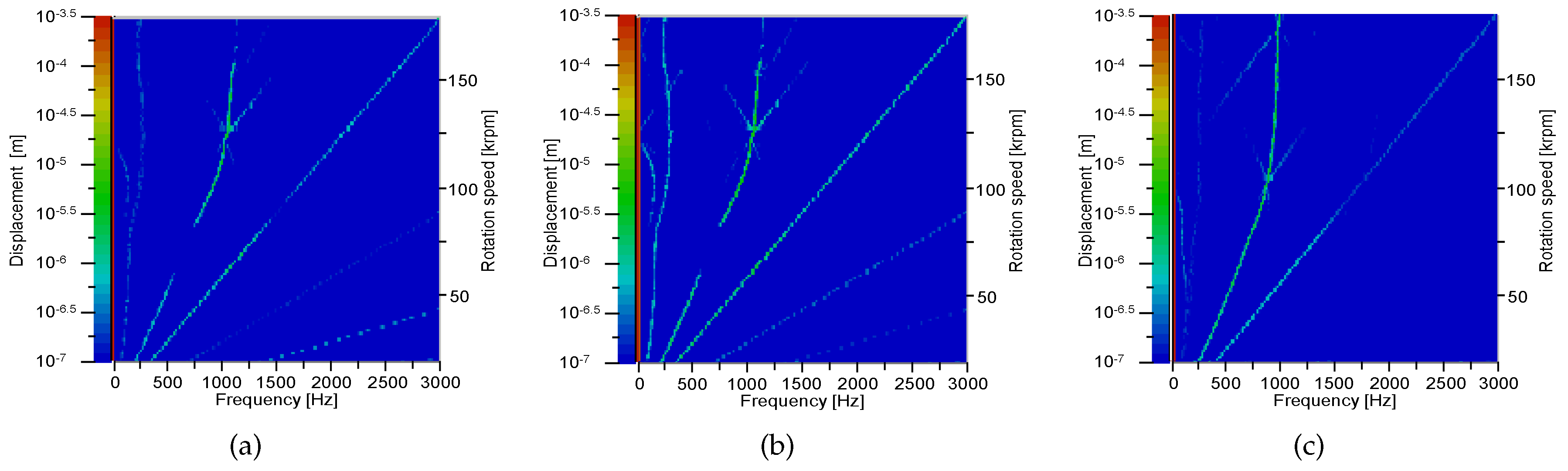
- From 20 to 62 krpm, some mild sub-synchronous oil whirl occured at a frequency of half the sum of the shaft speed and the ring speed: . The ring speeds will be presented in Figure 7.
- The synchronous response peaked at 68 krpm: the critical speed of this rotor-bearing system. After passing this critical speed, the synchronous response decayed again.
- At 83 krpm, an oil whirl starts, this time at a frequency somewhat below .
- At 115 krpm, the oil whirl interfered with half of the shaft rotation speed and jumped to a frequency of .
- At 130 krpm, the oil whirl locked into the first bending mode of the rotor-bearing system (which is the same mode that is triggered at 83 krpm by the synchronous excitation) and formed a whip.
- At 158 krpm, the oil whip vanished.
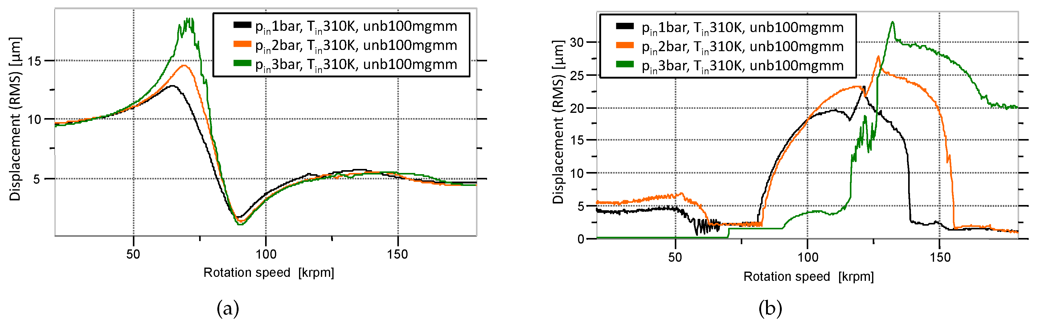
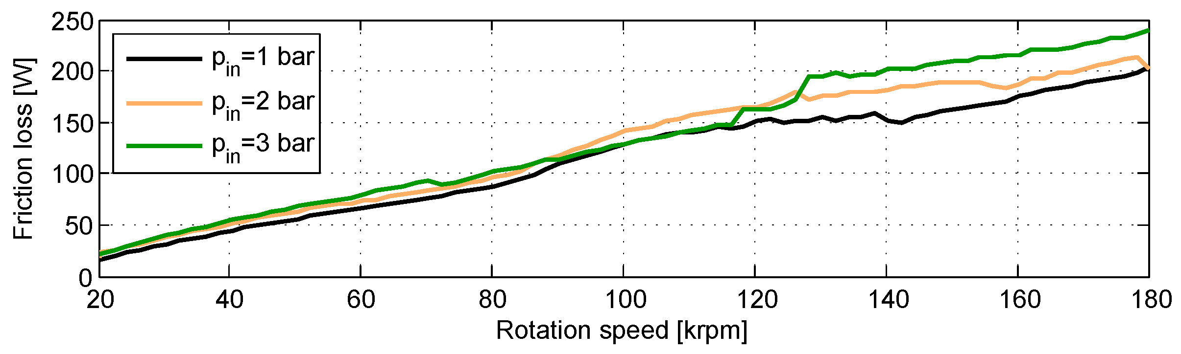
3.2. Response as a Function of Oil Feed Pressure
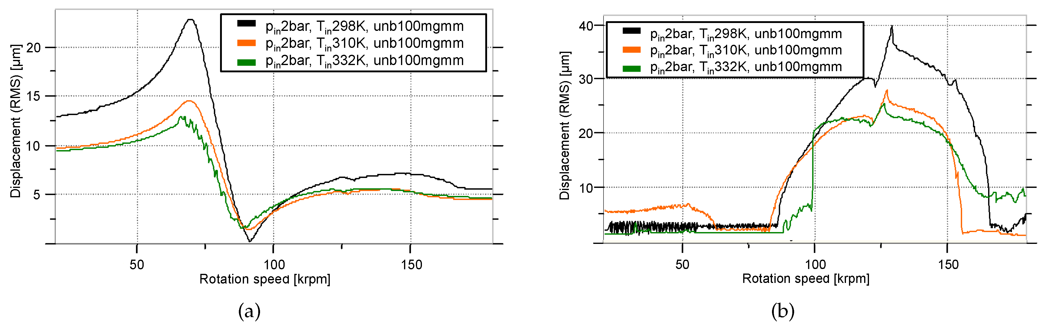
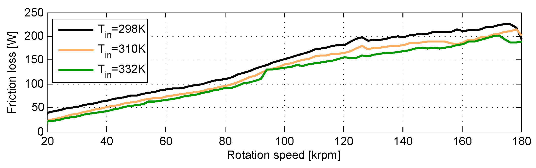
3.3. Response as a Function of Oil Feed Temperature
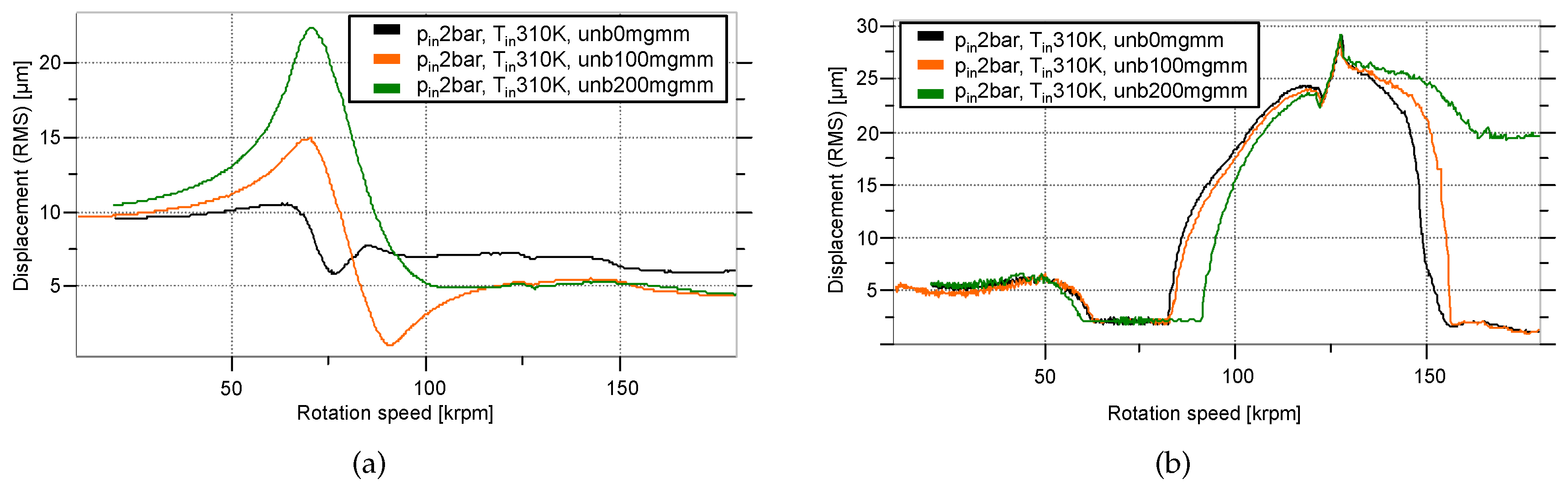
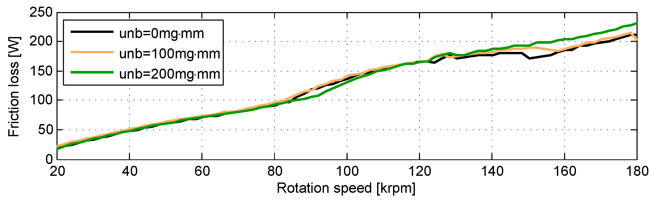
3.4. Response as a Function of Rotor Unbalance
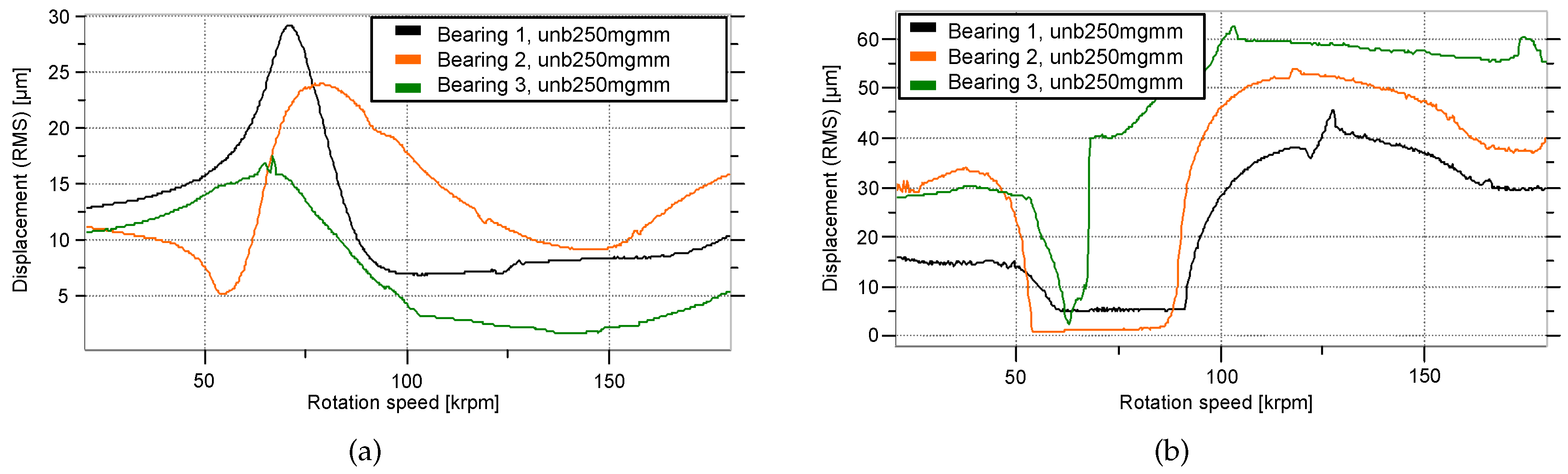
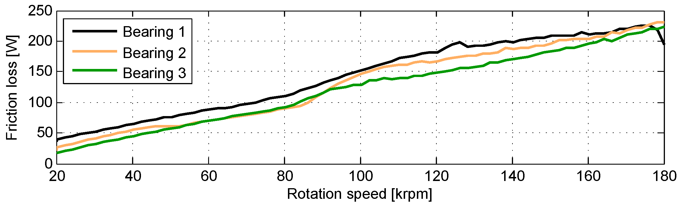
3.5. Response as a Function of Bearing Clearances
4. Conclusions
Author Contributions
Conflicts of Interest
References
- Schweizer, B. Total instability of turbocharger rotors—Physical explanation of the dynamic failure of rotors with full-floating ring bearings. J. Sound Vib. 2009, 328, 156–190. [Google Scholar] [CrossRef]
- Shaw, M.C., Jr.; Nussdorfer, T.J., Jr. An Analysis of the Full-Floating Journal Bearing; National Advisory Committee for Aeronautics: Washington, DC, USA, 1947; Volume 866. [Google Scholar]
- Nguyen-Schäfer, H. Rotordynamics of Automotive Turbochargers; Springer: Berlin/Heidelberg, Germany, 2012. [Google Scholar]
- San Andres, L.; Rivadeneira, J.C.; Gjika, K.; Groves, C.; LaRue, G. Rotordynamics of Small Turbochargers Supported on Floating Ring Bearings—Highlights in Bearing Analysis and Experimental Validation. J. Tribol. 2007, 129, 391. [Google Scholar] [CrossRef]
- Vetter, D.; Hagemann, T.; Schwarze, H. Predictions for run-up procedures of automotive turbochargers with full-floating ring bearings including thermal effects and different bearing setups. Tribol. Trans. 2014, 375–386. [Google Scholar] [CrossRef]
- Daniel, C.; Woschke, E.; Nitzschke, S.; Strackeljan, J.; Driot, N.; Braun, K.l.; Koutsovasilis, P. Validierung der Hochlaufsimulation für automotive Abgasturbolader. In Proceedings of the Internationale Tagung Schwingungen in Rotierenden Maschinen (SIRM2015–11), Magdeburg, Germany, 23–25 February 2015; pp. 1–9.
- Li, S.; Tuzcu, S.; Klaus, M.; Rienäcker, P.A.; Schwarze, P.H. Analyse der Einflüsse der hydrodynamischen Axiallagerung auf das rotordynamische Verhalten eines PKW-Abgasturboladers. In Proceedings of the Internationale Tagung Schwingungen in Rotierenden Maschinen (SIRM2015–11), Magdeburg, Germany, 23–25 February 2015; pp. 1–10.
- Tian, L.; Wang, W.J.; Peng, Z.J. Nonlinear effects of unbalance in the rotor-floating ring bearing system of turbochargers. Mech. Syst. Signal Process. 2013, 34, 298–320. [Google Scholar] [CrossRef]
- Porzig, D.; Raetz, H.; Schwarze, H.; Seume, J.R. Thermal analysis of small high-speed floating-ring journal bearings. In Proceedings of the 11th International Conference on Turbochargers and Turbocharging, London, UK, 13–14 May 2014; pp. 421–436.
- San Andres, L.; Barbarie, V.; Bhattacharya, A.; Gjika, K. On the Effect of Thermal Energy Transport to the Performance of (Semi) Floating Ring Bearing Systems for Automotive Turbochargers. J. Eng. Gas Turbines Power 2012, 134, 102507. [Google Scholar] [CrossRef]
- San Andres, L.; Maruyama, A.; Gjika, K.; Xia, S. Turbocharger Nonlinear Response With Engine-Induced Excitations: Predictions and Test Data. J. Eng. Gas Turbines Power 2010, 132, 032502. [Google Scholar] [CrossRef]
- Nguyen-Schäfer, H. Nonlinear Rotordynamic Computations of Automotive Turbochargers Using Rotating Floating Ring Bearings at High Rotor Speeds. In Proceedings of the 10th SIRM International Conference, Berlin, Germany, 25–27 February 2013; pp. 1–10.
- San Andres, L.; Vistamehr, A. Nonlinear rotordynamics of vehicle turbochargers: parameters affecting sub harmonic whirl frequencies and their jump. In Proceedings of the 8th IFToMM International Conference on Rotor Dynamics, Seoul, Korea, 12–15 September 2010; pp. 1077–1086.
- Alsaeed, A.A.; Kirk, R.G.; Bashmal, S. Effects of radial aerodynamic forces on rotor-bearing dynamics of high-speed turbochargers. Proc. Inst. Mech. Eng. C 2014, 228, 2503–2519. [Google Scholar] [CrossRef]
- Ying, G.; Meng, G.; Jing, J. Turbocharger rotor dynamics with foundation excitation. Arch. Appl. Mech. 2008, 79, 287–299. [Google Scholar] [CrossRef]
- Eling, R.; van Ostayen, R.; Rixen, D. Multilobe Floating Ring Bearings for Automotive Turbochargers. In Proceedings of the 9th IFToMM International Conference on Rotor Dynamics, Cham, Switzerland, 26 May 2015.
- Knauder, C.; Allmaier, H.; Sander, D.E.; Salhofer, S.; Reich, F.M.; Sams, T. Analysis of the Journal Bearing Friction Losses in a Heavy-Duty Diesel Engine. Lubricants 2015, 3, 142–154. [Google Scholar] [CrossRef]
- Tian, L.; Wang, W.J.; Peng, Z.J. Effects of bearing outer clearance on the dynamic behaviours of the full floating ring bearing supported turbocharger rotor. Mech. Syst. Signal Process. 2012, 31, 155–175. [Google Scholar] [CrossRef]
- Schweizer, B.; Sievert, M. Nonlinear oscillations of automotive turbocharger turbines. J. Sound Vib. 2009, 321, 955–975. [Google Scholar] [CrossRef]
- Serrano, J.R.; Olmeda, P.; Tiseira, A.; García-Cuevas, L.M.; Lefebvre, A. Theoretical and experimental study of mechanical losses in automotive turbochargers. Energy 2013, 55, 888–898. [Google Scholar] [CrossRef]
- Stachowiak, G.; Batchelor, A.W. Engineering Tribology, 4th ed.; Butterworth-Heinemann: Oxford, UK, 2014. [Google Scholar]
- Hoepke, B.; Uhlmann, T.; Pischinger, S.; Lueddecke, B.; Filsinger, D. Analysis of Thrust Bearing Impact on Friction Losses in Automotive Turbochargers. J. Eng. Gas Turbines Power 2015, 137, 82507. [Google Scholar] [CrossRef]
- Tian, L.; Wakelin, M.; Lancaster, C.; Lindsay, M. The Effect of Oil Film Instability on Power Losses Prediction of a Turbocharger Rotor-Fully Floating Ring Bearing System; Cummins Turbo Technologies: Huddersfield, UK, 2016. [Google Scholar]
- Trippett, R.J.; Li, D.F. High-speed Floating-Ring Bearing Test and Analysis. ASLE Trans. 1984, 27, 73–81. [Google Scholar] [CrossRef]
- Köhl, W.; Kreschel, M.; Filsinger, D. Modellabgleich eines Turboladerrotors in Schwimmbuchsenlagerung anhand gemessener Schwimmbuchsendrehzahlen. In Proceedings of the Internationale Tagung Schwingungen in Rotierenden Maschinen (SIRM2015–11), Magdeburg, Germany, 23–25 February 2015; Volume 5, pp. 1–10.
- Brouwer, M.D.; Sadeghi, F.; Lancaster, C.; Archer, J.; Donaldson, J. Whirl and Friction Characteristics of High Speed Floating Ring and Ball Bearing Turbochargers. J. Tribol. 2013, 135, 041102. [Google Scholar] [CrossRef]
- Deligant, M.; Podevin, P.; Descombes, G. Experimental identification of turbocharger mechanical friction losses. Energy 2012, 39, 388–394. [Google Scholar] [CrossRef]
- Bonneau, O.; Arghir, M.; Jolly, P. Dynamic control of a flexible shaft mounted in adaptive or active bearing. J. Mech. Eng. Autom. 2014, 4, 1–7. [Google Scholar]


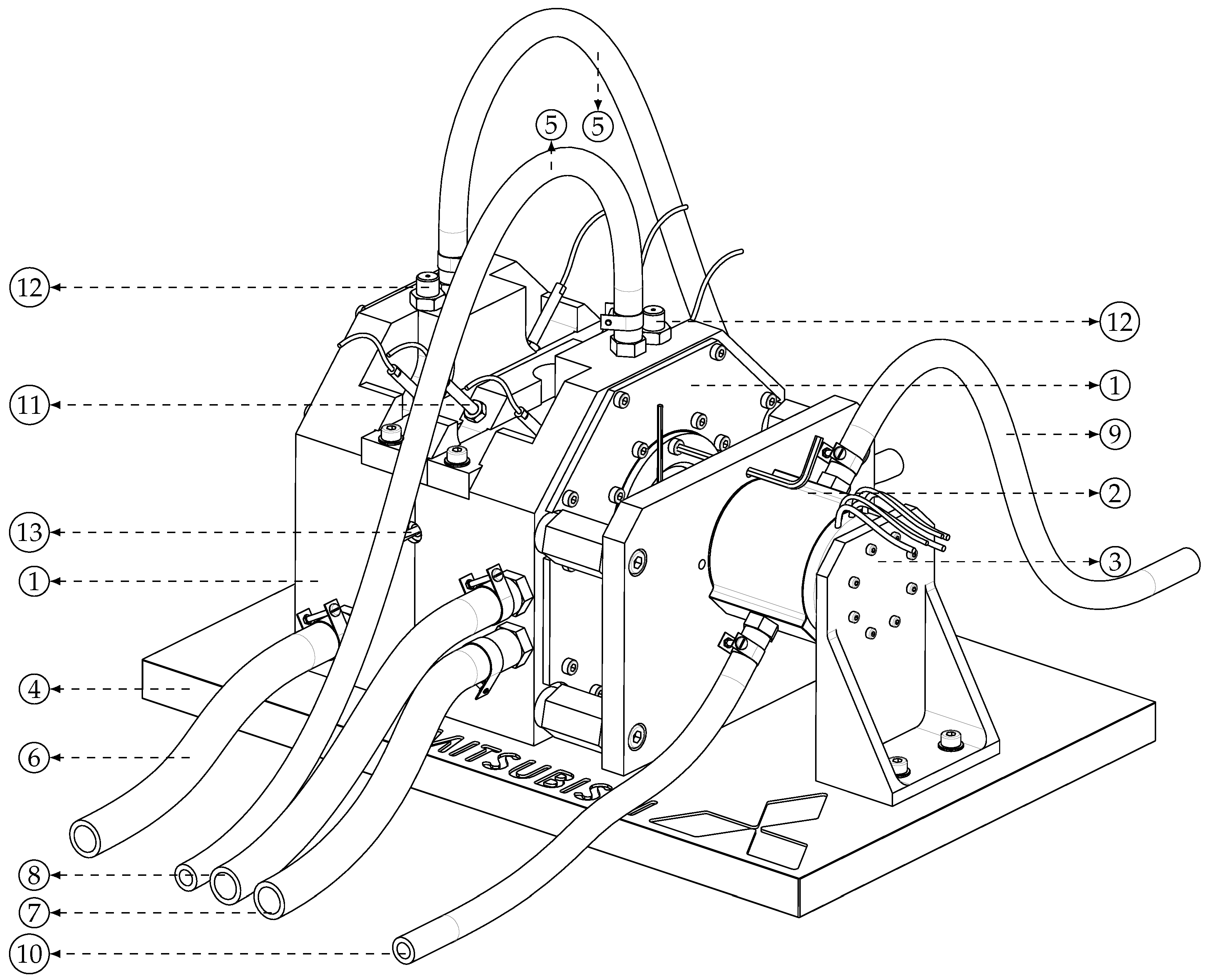
| Number | Description | Number | Description |
|---|---|---|---|
| 1 | Bearing housing | 8 | Liquid cooling/heating drain |
| 2 | Motor | 9 | Motor cooling supply |
| 3 | Motor support bracket | 10 | Motor cooling drain |
| 4 | Baseplate | 11 | Shaft displacement sensor |
| 5 | Oil supply line | 12 | Thermocouple |
| 6 | Oil drain line | 13 | Optical sensor |
| 7 | Liquid cooling/heating supply |
| Rotor Parameters | Ring Parameters | ||||||
|---|---|---|---|---|---|---|---|
| Name | Value | Unit | Description | Name | Value | Unit | Description |
| 3.75 | mm | Radius of shaft | 8.5 | m | Inner clearance | ||
| 15 | mm | Radius of center disk | 30 | m | Outer clearance | ||
| 6 | mm | Radius measurement disk | 5 | mm | Length inner film | ||
| 5 | mm | Radius of fillet | 8 | mm | Length outer film | ||
| 137 | mm | Shaft length | 6.465 | mm | Outer ring radius | ||
| 9 | mm | Length of center disk | 1.5 × | kg· | Ring rotation inertia | ||
| 5 | mm | Length measurement disk | 8750 | kg· | Material density | ||
| 1.2 × | Coeff. thermal expansion | 110 | GPa | Material E-modulus | |||
| 80 | mm | Length of bearing span | 5.39 | g | Ring mass | ||
| 58 | mm | Measurement disk span | 1.4 × | Coeff. th. expansion | |||
| 8 | mm | Length of coupling section | Oil Parameters | ||||
| 2.25 | mm | Radius of coupling section | 855 | kg· | Oil density | ||
| 7700 | kg· | Material density | 2.1 | kJ/kg·K | Heat capacity | ||
| 210 | GPa | Material E-modulus | 0.145 | W/m·K | Thermal conductance | ||
| 9.2 × | kg· | Rotor rotation inertia | 0.44 | mPa·s | Temperature coeff. | ||
| 101 | g | Rotor mass | 633 | °C | Temperature coeff. | ||
| 88.6 | °C | Temperature coeff. | |||||
| 0.5 | - | Shear rate coefficient | |||||
| 0.8 | - | Shear rate coefficient | |||||
| 7.2 × | Shear rate coefficient | ||||||
| Inner Clearance (m) | Outer Clearance (m) | |
|---|---|---|
| Bearing clearance configuration 1 | 8.5 | 30 |
| Bearing clearance configuration 2 | 13 | 35 |
| Bearing clearance configuration 3 | 16.5 | 41 |
© 2017 by the authors. Licensee MDPI, Basel, Switzerland. This article is an open access article distributed under the terms and conditions of the Creative Commons Attribution (CC BY) license ( http://creativecommons.org/licenses/by/4.0/).
Share and Cite
Eling, R.; Te Wierik, M.; Van Ostayen, R.; Rixen, D. Rotordynamic and Friction Loss Measurements on a High Speed Laval Rotor Supported by Floating Ring Bearings. Lubricants 2017, 5, 7. https://doi.org/10.3390/lubricants5010007
Eling R, Te Wierik M, Van Ostayen R, Rixen D. Rotordynamic and Friction Loss Measurements on a High Speed Laval Rotor Supported by Floating Ring Bearings. Lubricants. 2017; 5(1):7. https://doi.org/10.3390/lubricants5010007
Chicago/Turabian StyleEling, Rob, Mathys Te Wierik, Ron Van Ostayen, and Daniel Rixen. 2017. "Rotordynamic and Friction Loss Measurements on a High Speed Laval Rotor Supported by Floating Ring Bearings" Lubricants 5, no. 1: 7. https://doi.org/10.3390/lubricants5010007