
Influence of Organo-Sulfur Compounds with Overbased Calcium Compounds on Lubrication in Cold Forming

Abstract
:1. Introduction
2. Experimental Methods
2.1. Additives and Test Oils Used
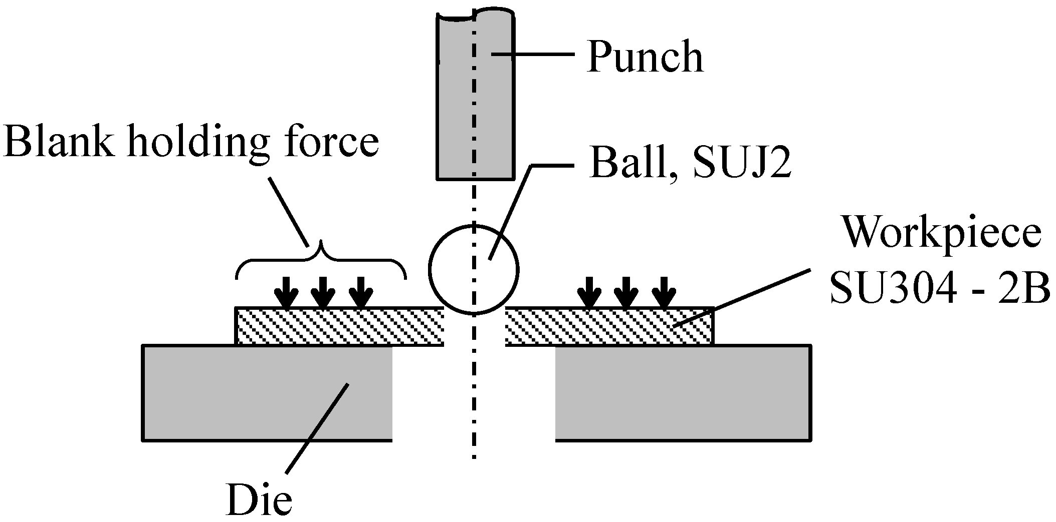
2.2. Burring Test
2.2.1. Test Procedure
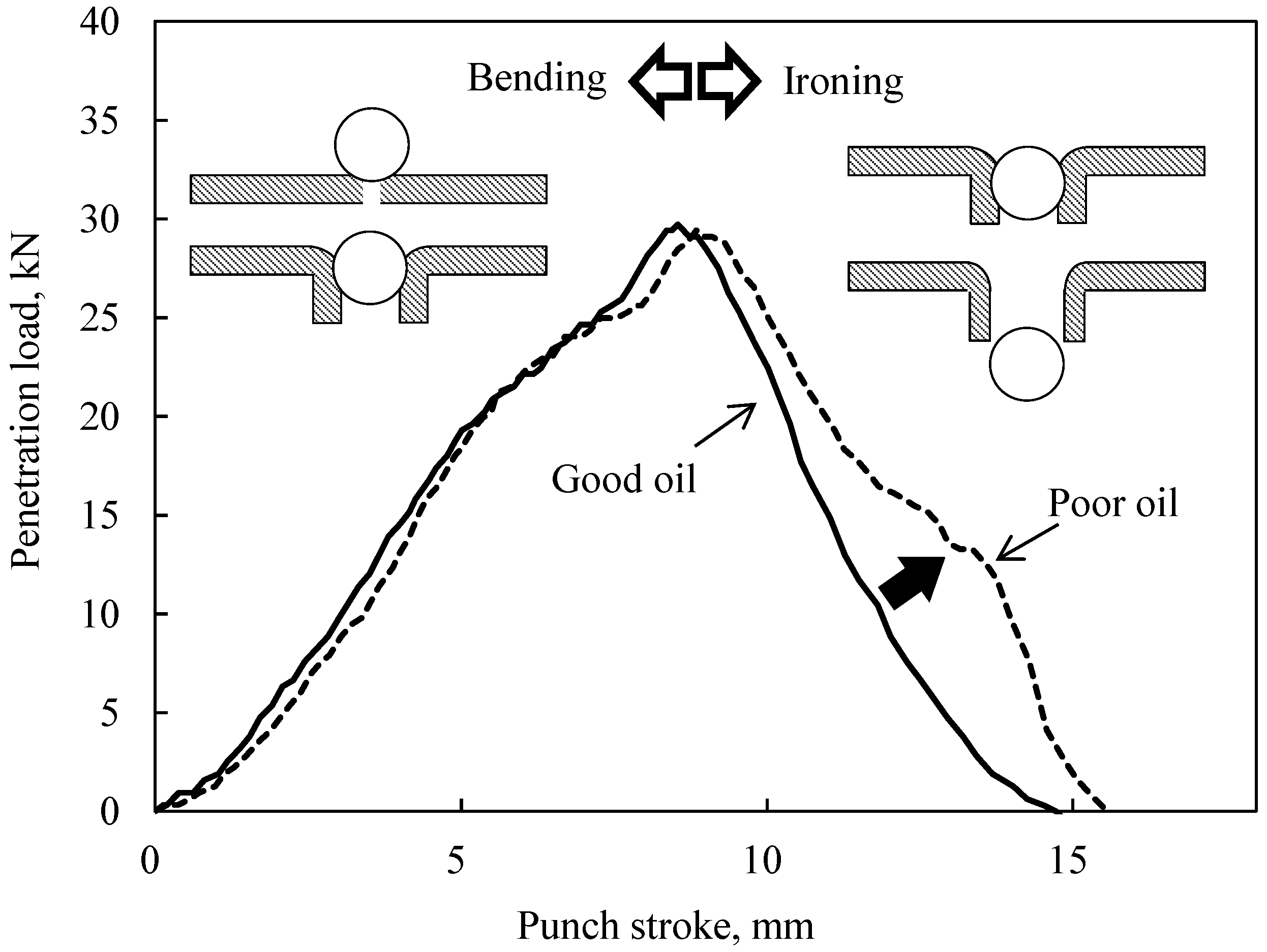
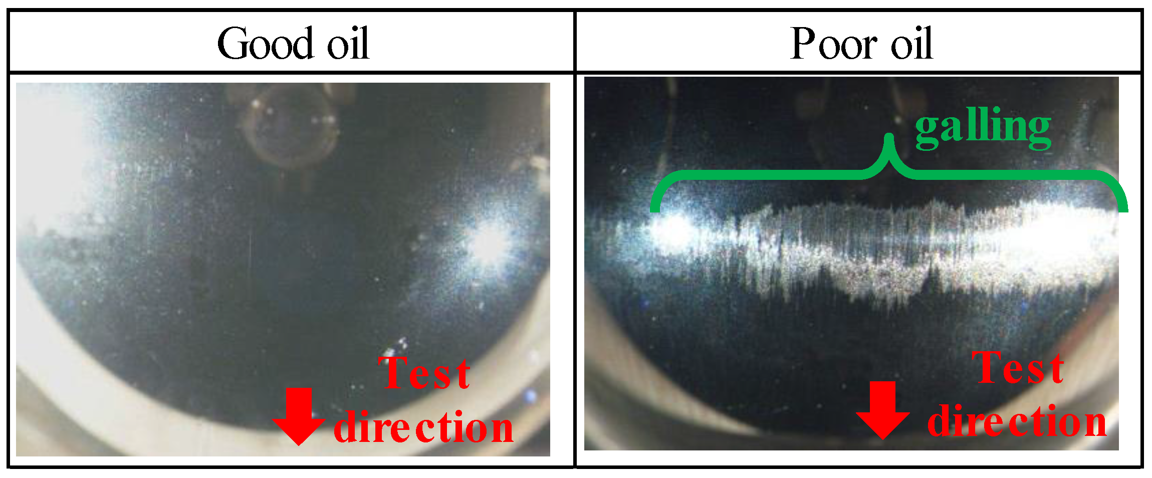
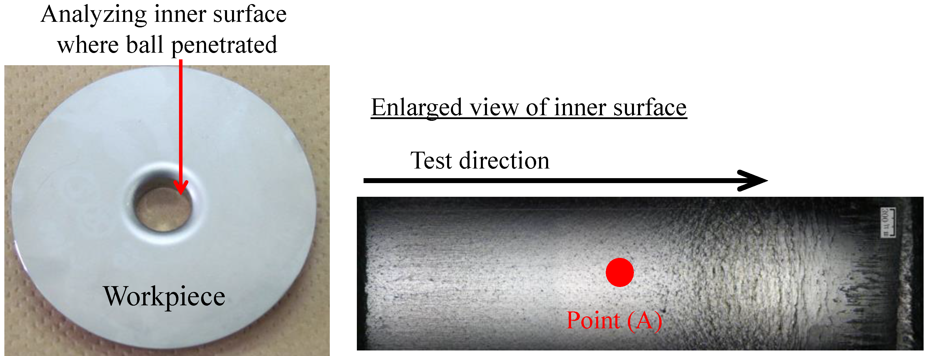
2.2.2. Evaluation Method of the Ironing Performance
2.3. Surface Analysis
3. Results and Discussion
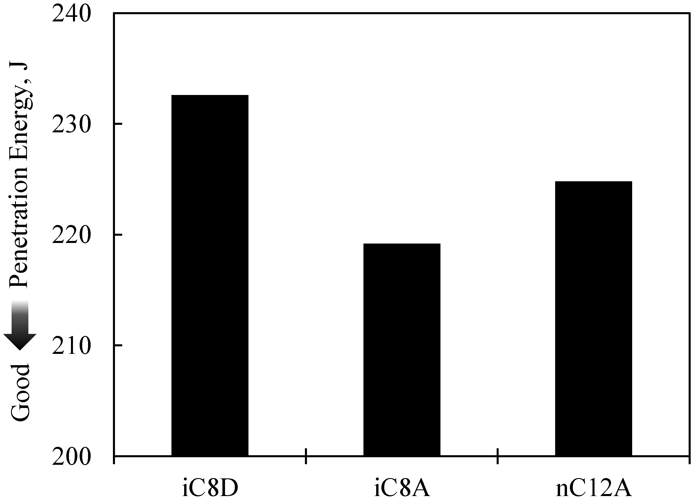
3.1. Results of the Burring Test
3.2. Results of Surface Anaylsis
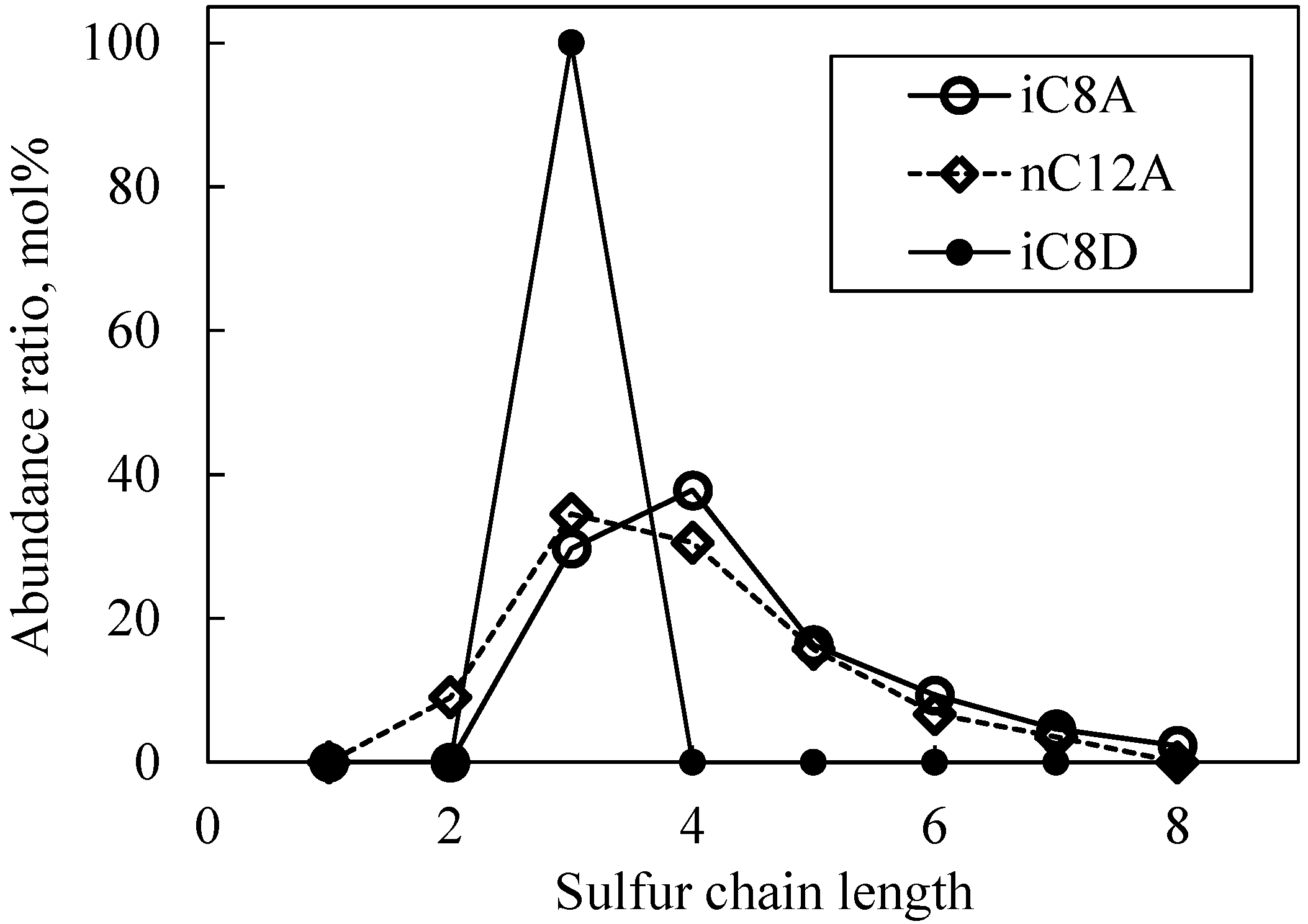
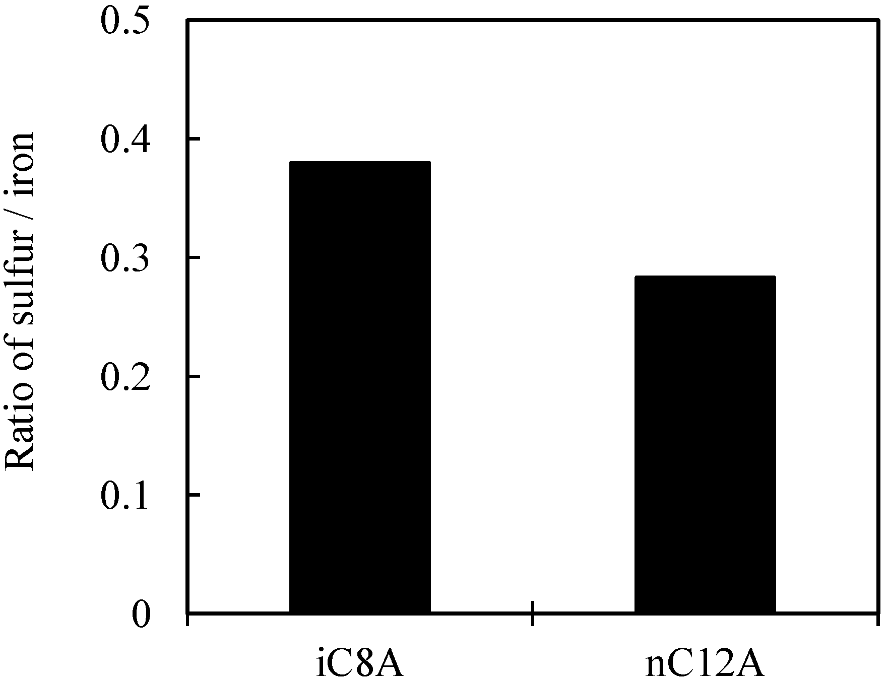
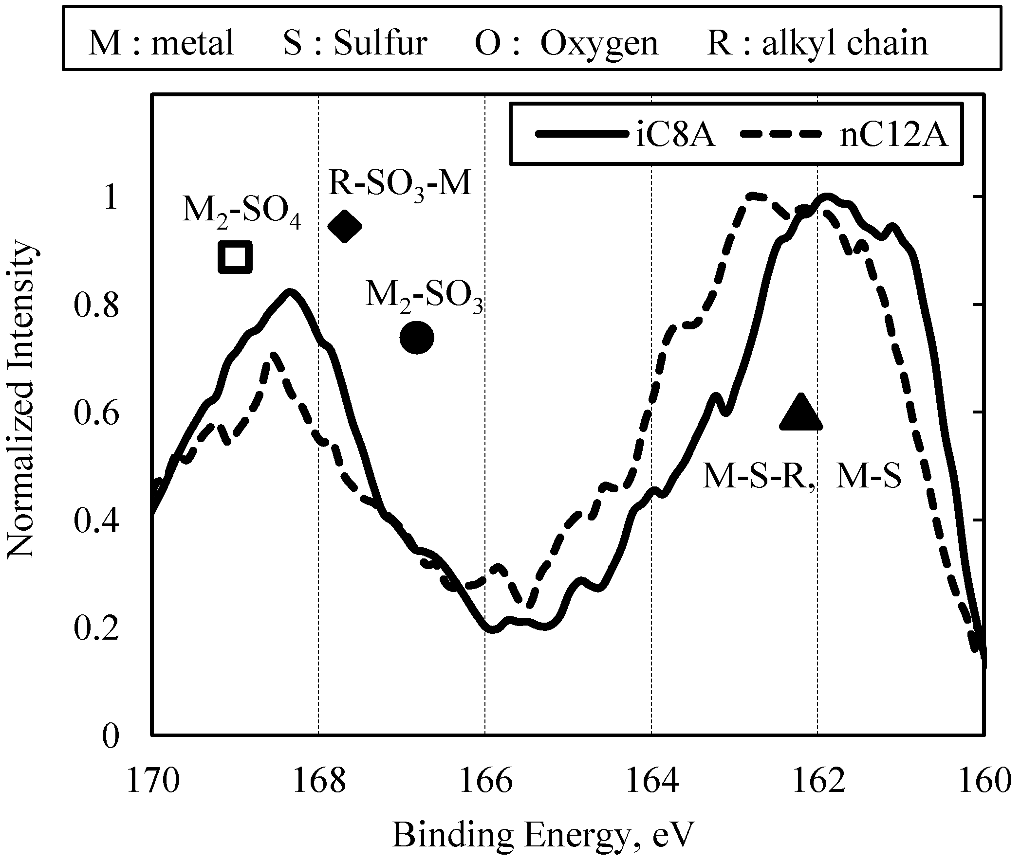
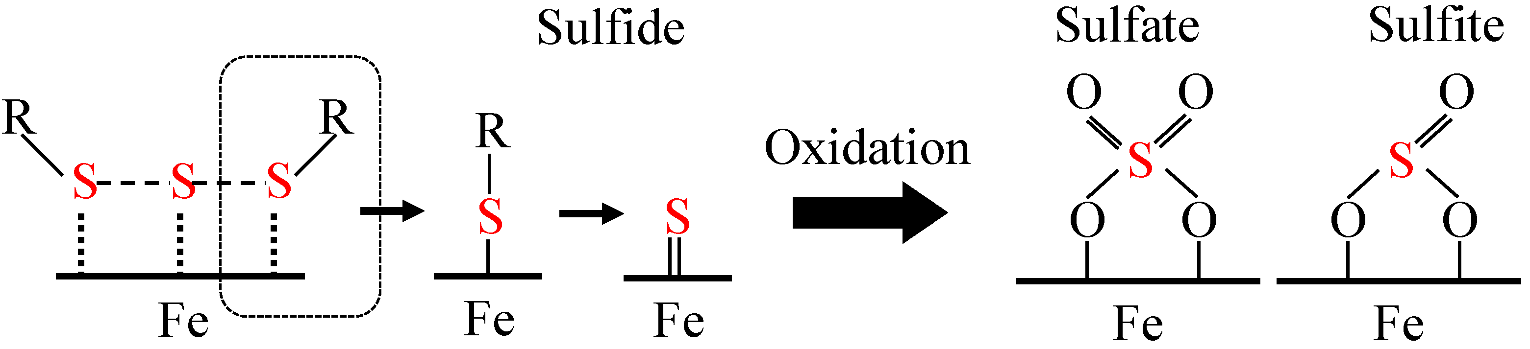
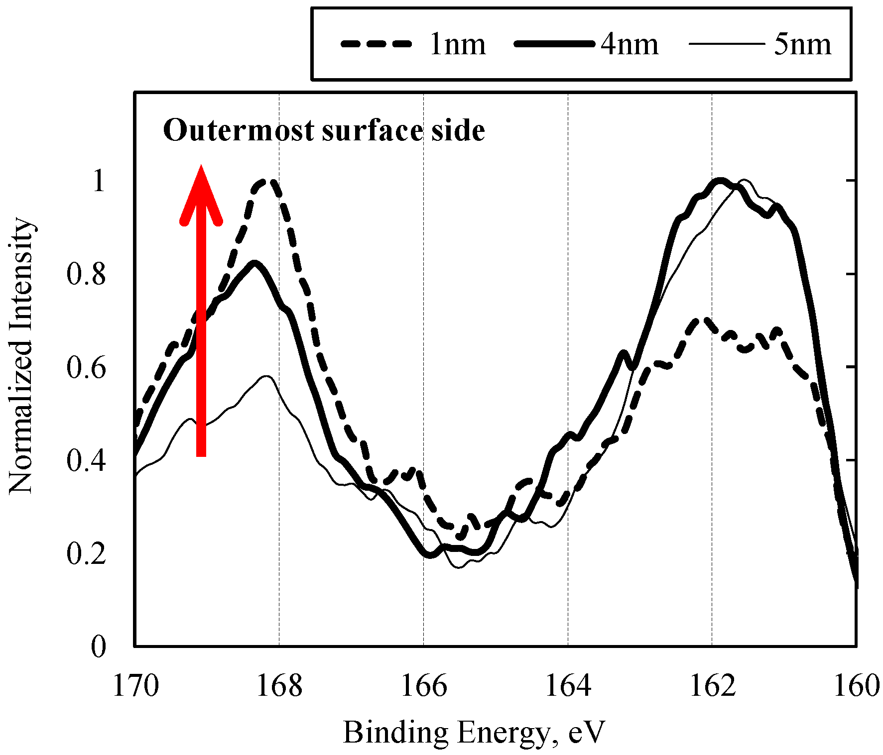
3.2.1. Sulfurized Olefins Alone
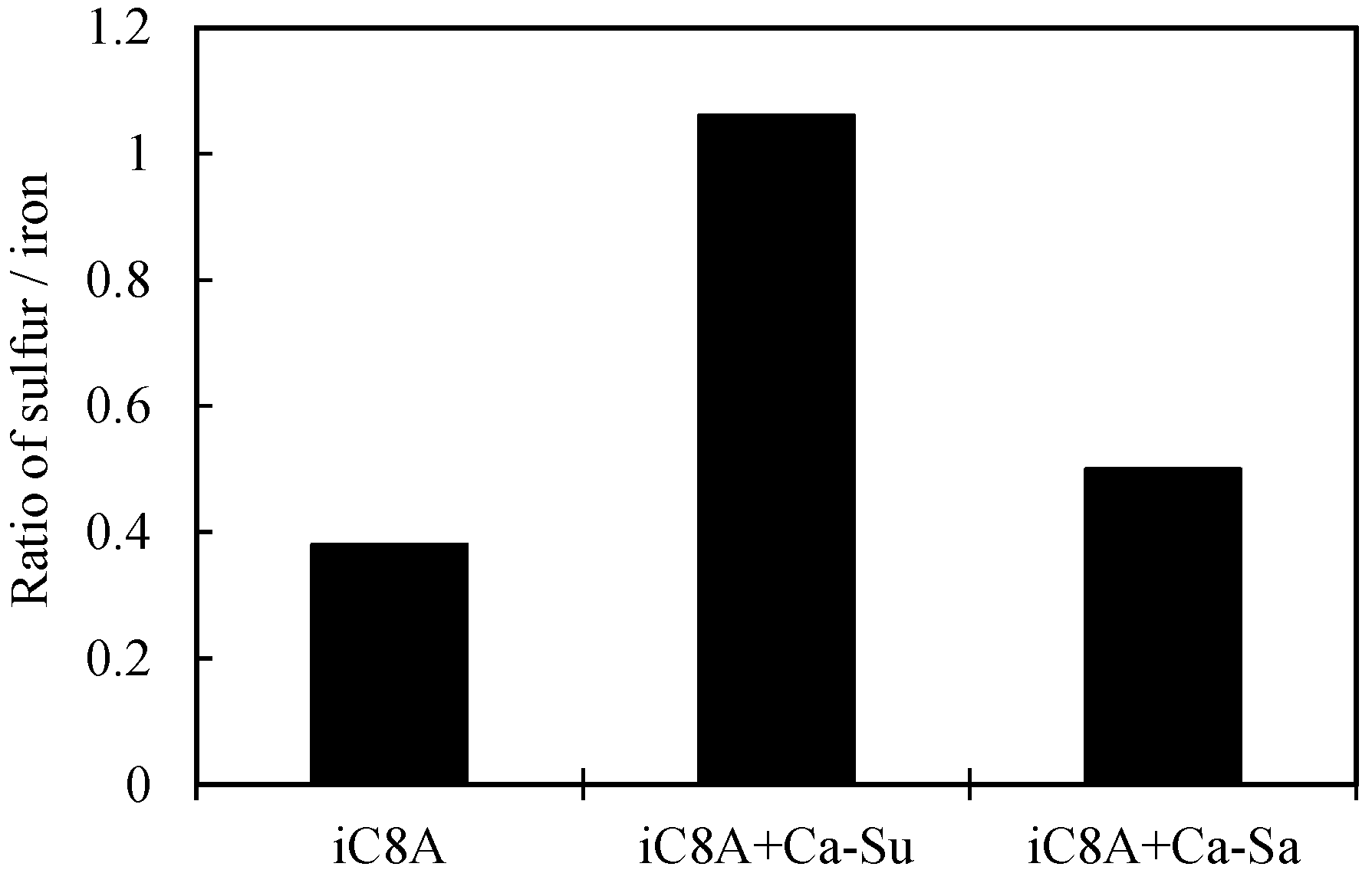
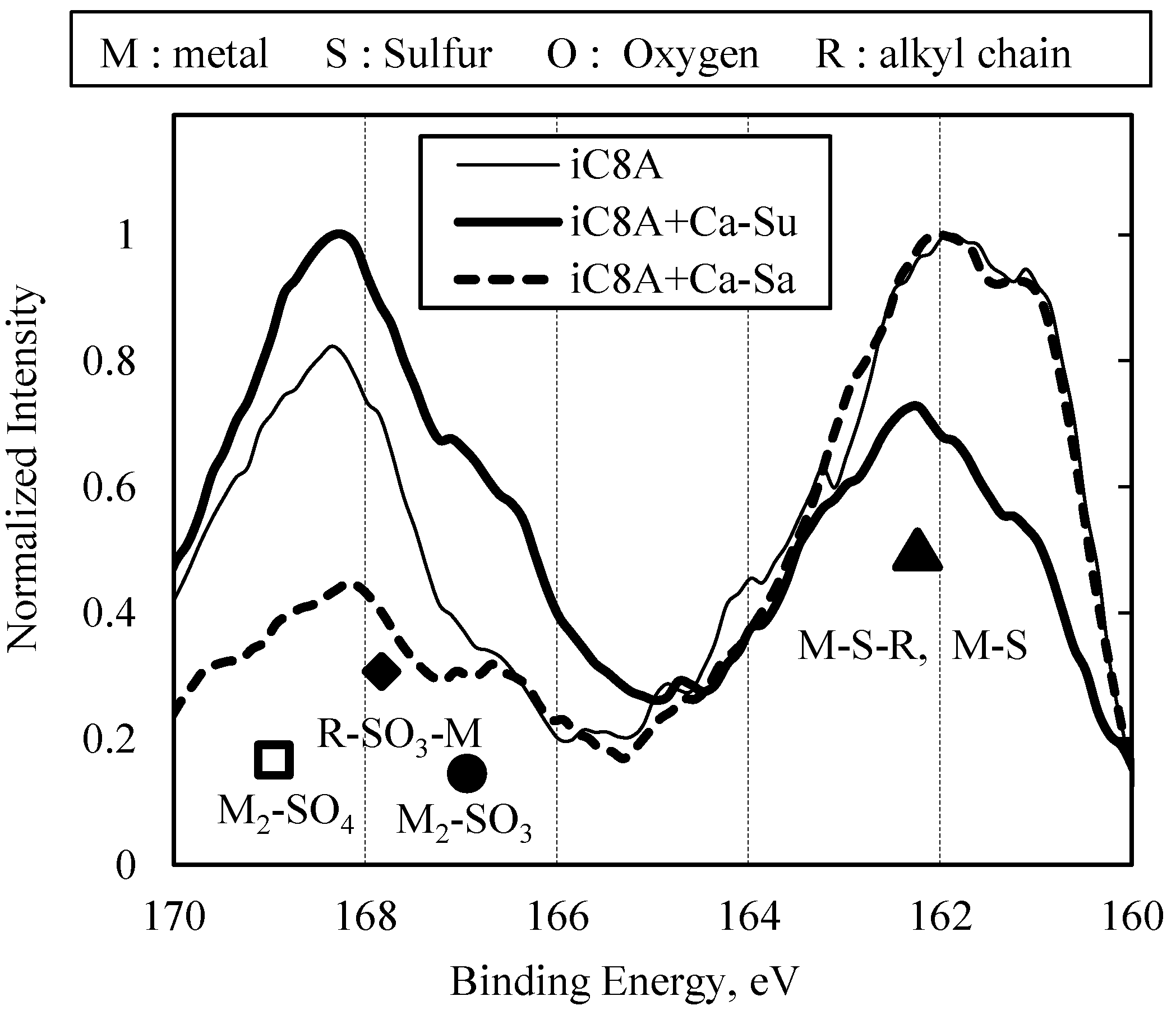
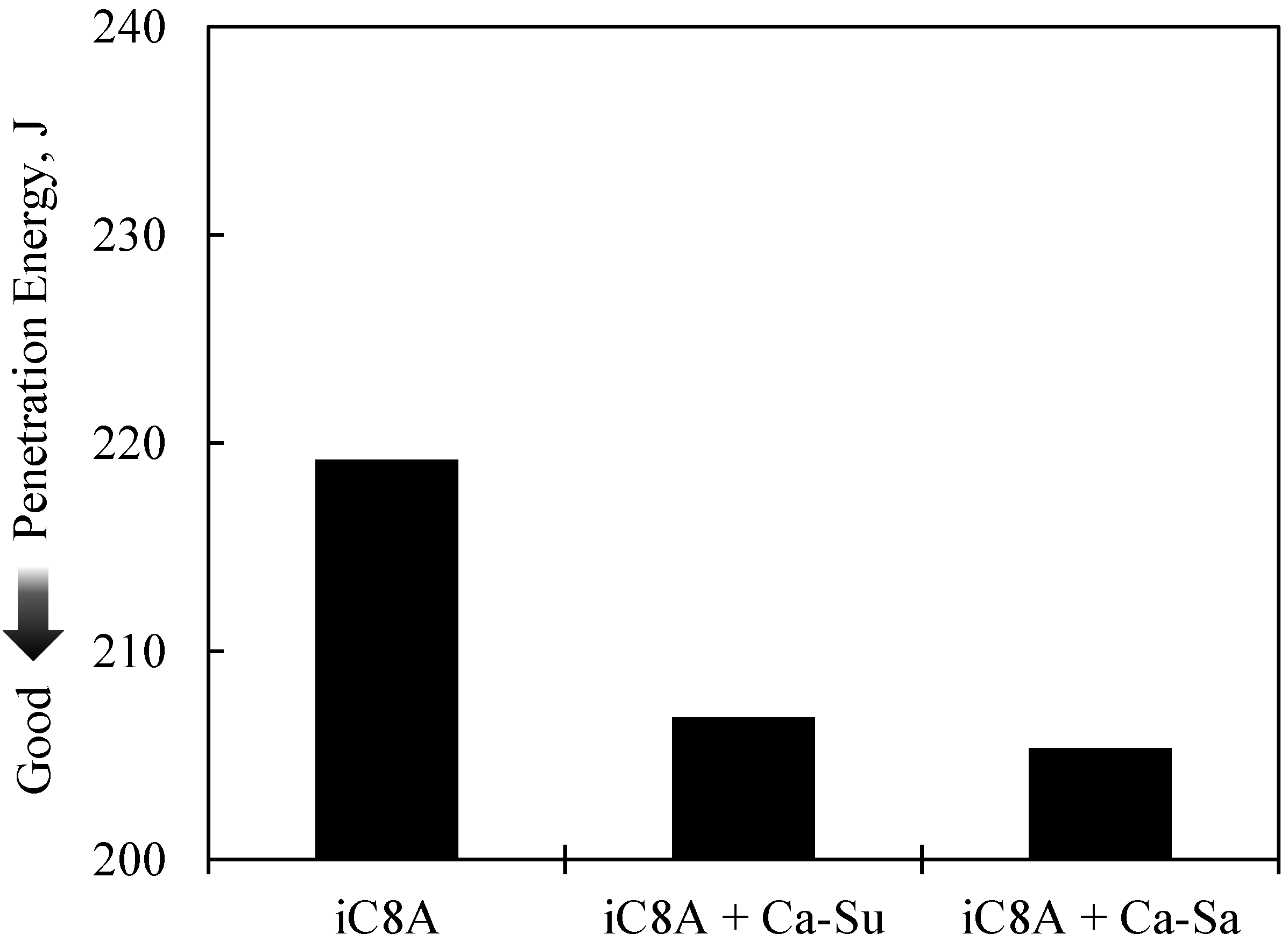
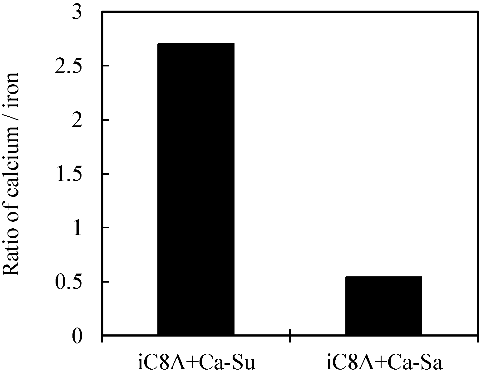
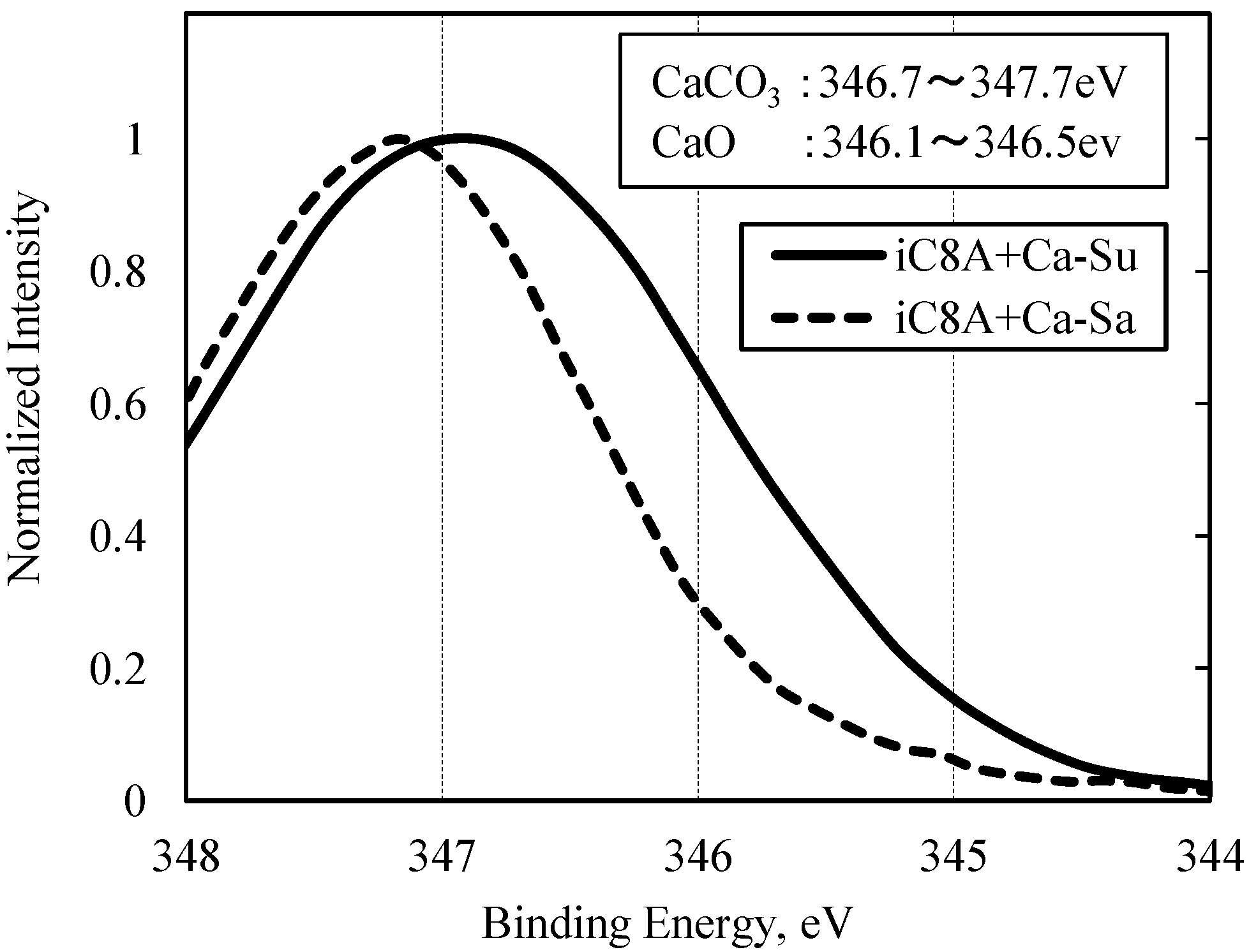
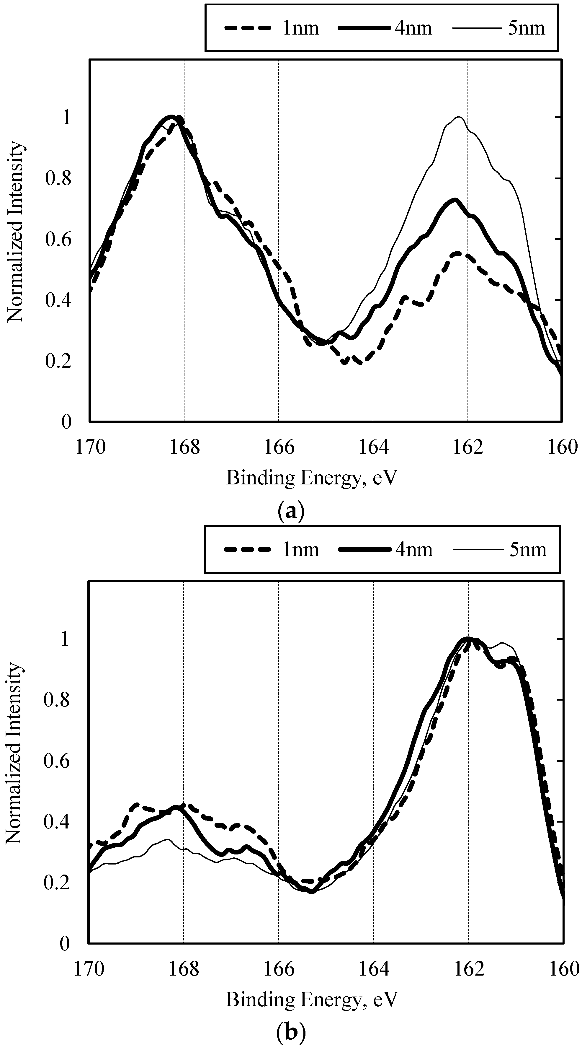
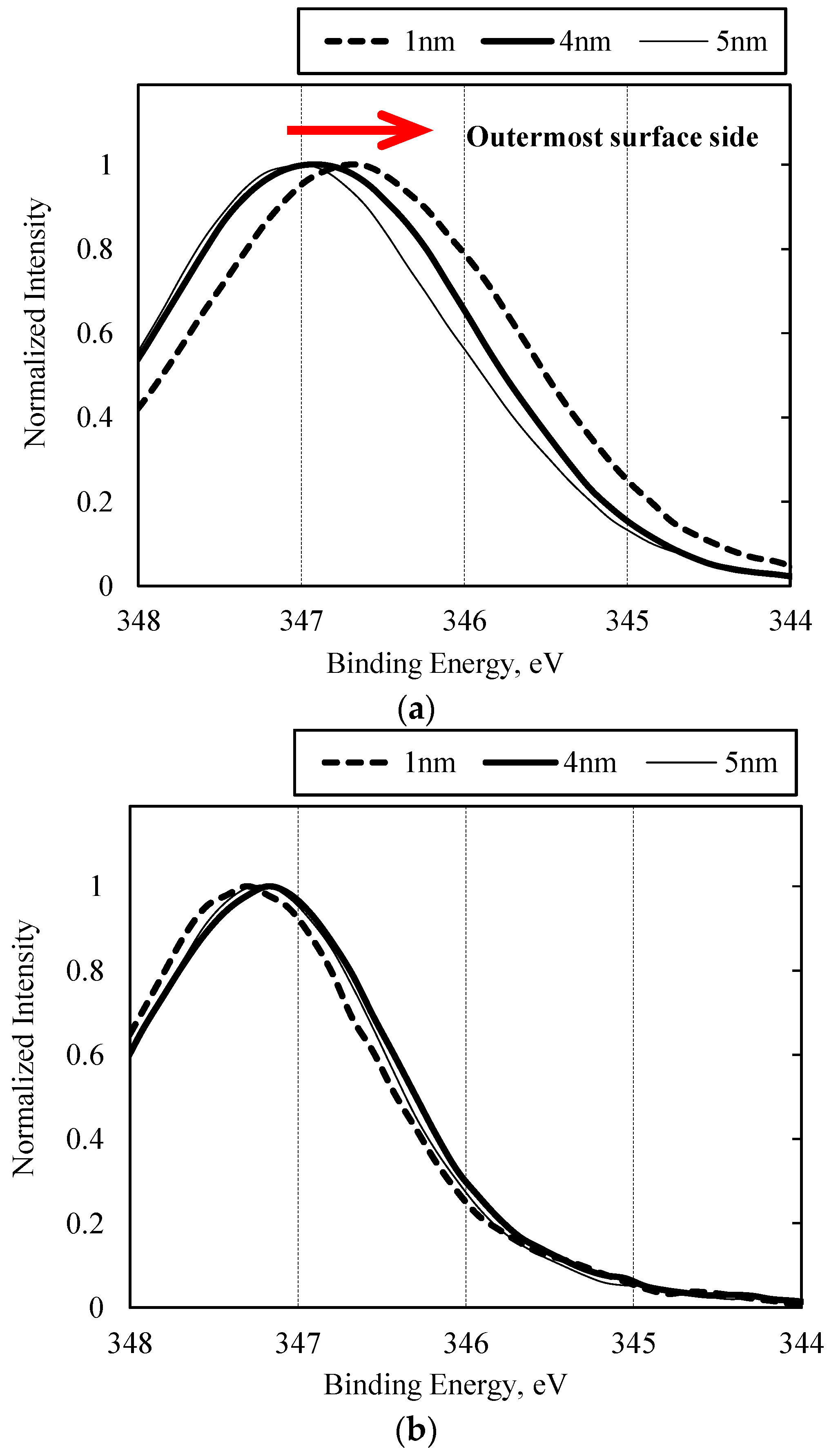
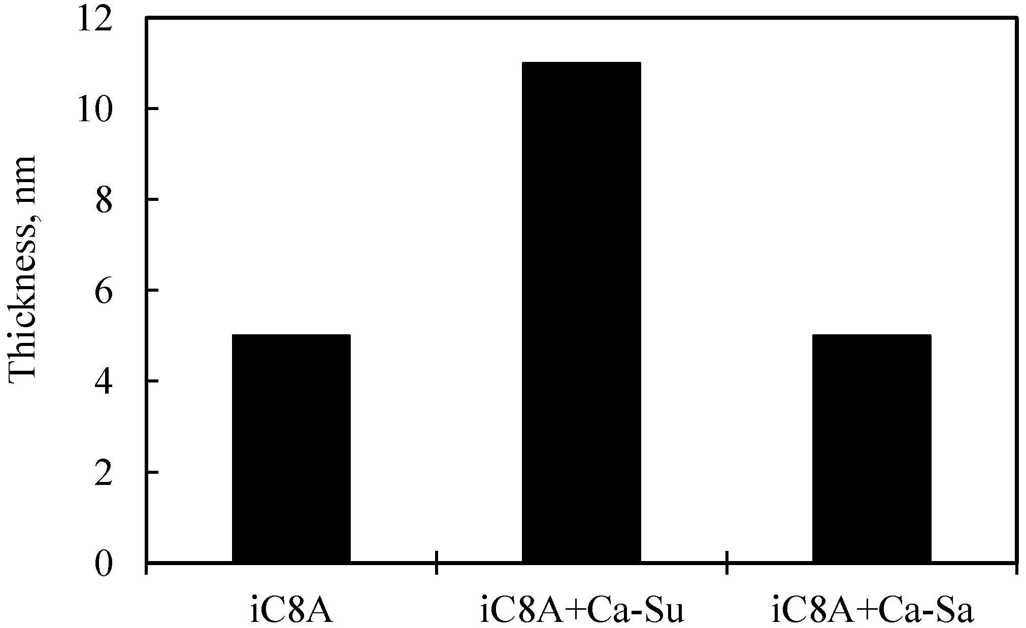
3.2.2. Combination of Sulfurized Olefins with Overbased Calcium Compounds
4. Conclusions
- (1)
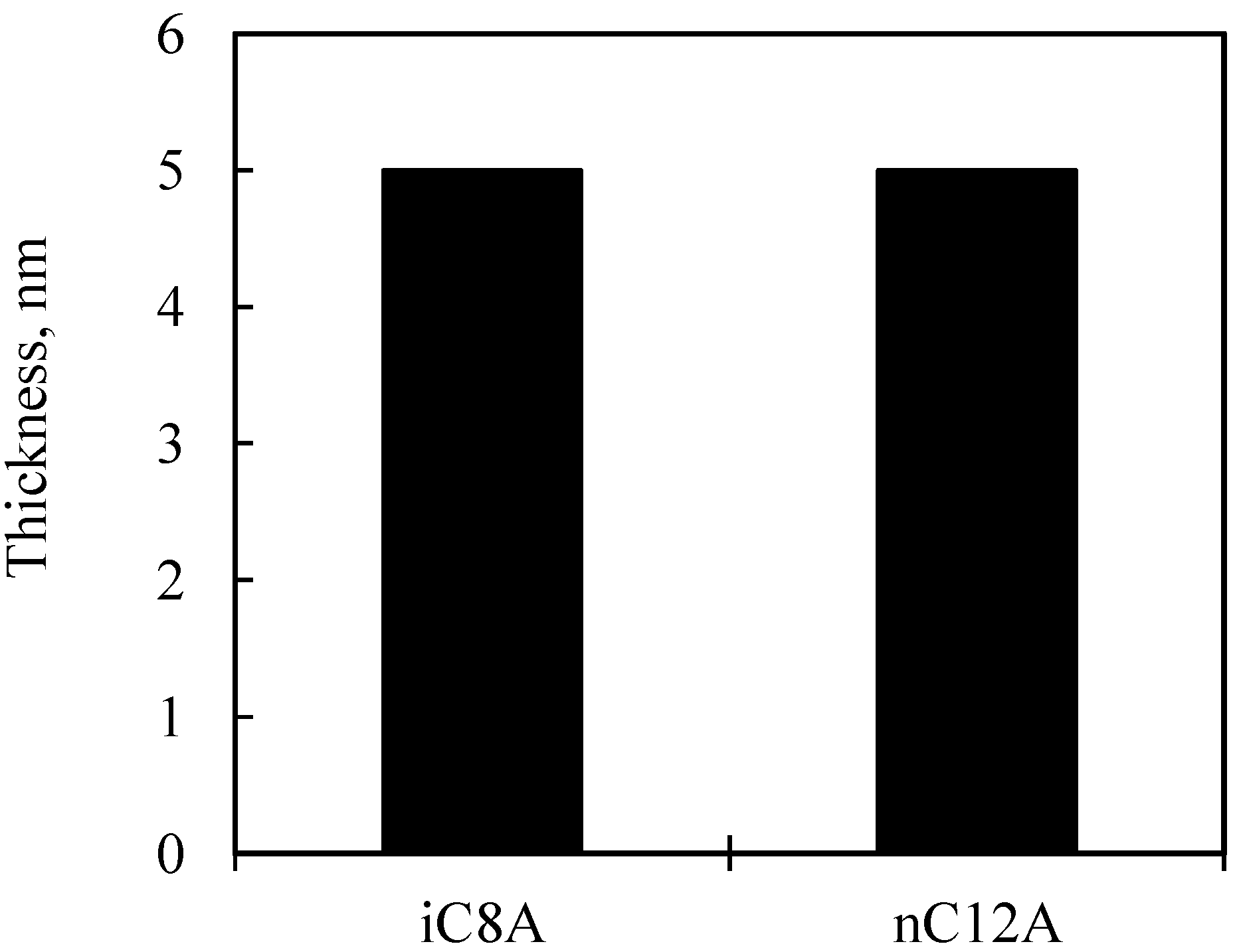
- With sulfurized olefins, sulfur chain length and alkyl structure play an important role in ironing performance. The branched type sulfurized olefins had better performance because a denser layer of iron sulfide was formed on the workpiece surface.
- (2)
- When the sulfurized olefins were combined with overbased calcium sulfonate or salicylate, the performance was better than with sulfurized olefins alone. The combined effect of sulfurized olefins and salicylate was revealed for the first time.
- (3)
- There were differences in the tribofilms formed with the oils prepared with calcium sulfonate and salicylate. However, what was common to both was that iron sulfide and calcium carbonate were detected on the surface of the workpiece after the burring test. Thus, lubricating films consisting of both iron sulfide and calcium carbonate seem to improve ironing performance.
Acknowledgments
Author Contributions
Conflicts of Interest
References
- Hosford, W.F.; Caddell, R.M. Metal Forming Mechanics and Metallurgy, 4th ed.; Cambridge University Press: New York, NY, USA, 2011; pp. 106–112. [Google Scholar]
- Allum, K.G.; Forbers, E.S. The Load-Carrying Mechanism of Organic Sulfur Compounds—Application of Electron Probe Microanalysis. ASLE Trans. 1968, 11, 162–175. [Google Scholar] [CrossRef]
- Mori, S.; Hori, K.; Tamai, Y. Mechanochemical Reaction of Extreme Pressure Additive with Mild Steel. J. Jpn. Soc. Tribol. 1982, 27, 505–511. (In Japanese) [Google Scholar]
- Kubo, T.; Minami, I.; Mori, S. Investigation of tribocemical reaction by organic sulfides on nascent metal surfaces. Tribol. Online 2007, 2, 89–92. [Google Scholar] [CrossRef]
- Wakabayashi, T.; Yokota, H.; Okajima, M.; Ogura, S. Effect of Cutting Oils and Infuleence of Tool Materials on Metal Cutting (Part 1). J. Jpn. Soc. Tribol. 1994, 39, 784–791. (In Japanese) [Google Scholar]
- Kubo, T.; Nanao, H.; Minami, I.; Mori, S. TOF-SIMS Analysis of Boundary Film Dervied from Multi-Additives. J. Jpn. Soc. Tribol. 2006, 51, 819–825. (In Japanese) [Google Scholar]
- Kubo, T.; Nanao, H.; Minami, I.; Mori, S. TOF-SIMS Analysis of Boundary Film Dervied from Multi-Additives (Part 2)—Chemical Analysis with Depth Profiling. J. Jpn. Soc. Tribol. 2007, 52, 871–879. (In Japanese) [Google Scholar]
- Costello, M.T.; Kasrai, M. Study of surface films of overbased sulfonates and sulfurized olefins by X-Ray Absorption Near Edge Structure (XANES) spectroscopy. Tribol. Lett. 2006, 24, 163–169. [Google Scholar] [CrossRef]
- Sembongi, N.; Tsujimoto, T.; Takaki, T.; Yagishita, K.; Wakabayashi, T. Relationship between molecular structure of organo-sulfur compounds and machining performance. In Proceedings of the 19th International Colloquium Tribology, Stuttgard, Germany, 21–23 January 2014.
- Takaki, T.; Ito, S.; Kitamura, K.; Yagishita, K.; Shibata, J. Relationship between Molecular Structures of Organic-Sulfur Compounds and Metal Forming Performance. Key Eng. Mater. 2016, 716, 190–198. [Google Scholar] [CrossRef]
- Ohmori, T.; Kitamura, K.; Danno, A.; Kawamura, M. A Cold Forging Oil Containing Phosphorus Type EP Additives. Tribol. Trans. 1991, 34, 458–464. [Google Scholar] [CrossRef]
- Mizuno, K.; Kitamura, K.; Sasai, A. An Experiment of Burring (Hole Flanging of Metal Sheet). In Proceedings of the 50th Japanese Joint Conference for the Technology of Plasticity, Fukuoka, Japan, 6–8 October 1999. (In Japanese)
- Harada, T. Practical application of chlorine-free oils to press forming. Press Form. J. 2009, 8, 15–16. (In Japanese) [Google Scholar]
- Fujita, M. Component Analysis of Lubricants. J. Jpn. Soc. Tribol. 1967, 12, 5–14. [Google Scholar]
- Yamamura, Y.; Shimizu, R.; Shimizu, H.; Itoh, N. Ion-Induced Sputtering. Shinku 1983, 26, 69–87. (In Japanese) [Google Scholar] [CrossRef]
- Forbes, E.S.; Reid, A.J.D. Liquid Phase Adsorption/Reaction Studies of Organo-Sulfur Compounds and Their Load-Carrying Mechanism. ASLE Trans. 1973, 16, 50–60. [Google Scholar] [CrossRef]
- Cizairea, L.; Martina, J.M.; Gresserb, E.; Dinhc, N.T.; Heau, C. Chemical analysis of overbased calcium sulfonate detergents by coupling XPS, ToF-SIMS, XANES, and EFTEM. Tribol. Lett. 2004, 238, 151–158. [Google Scholar] [CrossRef]


| Sample name | Molecular structure: | Sulfur chain length: | Alkyl: |
|---|---|---|---|
 | n | R | |
| iC8D |  | 3 (Inactive) | C8 (Branched) |
| iC8A |  | 3–8 (Active) | C8 (Branched) |
| nC12A | 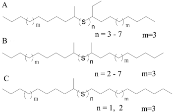 | 2–7 (Active) | C12 (Straight) |
| Sample | Structure of soap | Alkyl: R | Base number, mg KOH/g |
|---|---|---|---|
| Ca-Su |  | 18 | 400 |
| 20 | |||
| 22 | |||
| 24 | |||
| Ca-Sa | 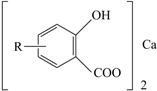 | 20 | 320 |
| 22 | |||
| 24 | |||
| 28 | |||
| 30 |
| Workpiece | Material | SUS304-2B (in JIS *) |
| Diameter, mm | 80 | |
| Thickness, mm | 2 | |
| Hole diameter, mm | 4 | |
| Ball | Quality of material | SUJ2 (in JIS *) |
| Diameter, mm | 14.25 | |
| Test speed, mm/s | 10 | |
| Blank holding force, kN | 19.6 | |
| XPS | Device name: | Quantum-2000 (manufactured by PHI) |
| X-ray source: | Monochromatic-Al-Kα radiation (1486.6 eV) | |
| Analysis area: | DIA 200 μm (elliptical shape) | |
| Take-off angle of the photoelectrons: | 45° (standard) | |
| 15°, 75° (angle-resolved XPS) | ||
| AES | Device name: | Model-680 (manufactured by PHI) |
| Electron accelerating voltage: | 10 kV | |
| Ion accelerating voltage: | 3 kV | |
| Sputtering rate: | 18 nm/min (relative to SiO2) |
© 2017 by the authors. Licensee MDPI, Basel, Switzerland. This article is an open access article distributed under the terms and conditions of the Creative Commons Attribution (CC BY) license ( http://creativecommons.org/licenses/by/4.0/).
Share and Cite
Takaki, T.; Yagishita, K.; Tsujimoto, T.; Wakabayashi, T. Influence of Organo-Sulfur Compounds with Overbased Calcium Compounds on Lubrication in Cold Forming. Lubricants 2017, 5, 8. https://doi.org/10.3390/lubricants5010008
Takaki T, Yagishita K, Tsujimoto T, Wakabayashi T. Influence of Organo-Sulfur Compounds with Overbased Calcium Compounds on Lubrication in Cold Forming. Lubricants. 2017; 5(1):8. https://doi.org/10.3390/lubricants5010008
Chicago/Turabian StyleTakaki, Tomohiro, Kazuhiro Yagishita, Teppei Tsujimoto, and Toshiaki Wakabayashi. 2017. "Influence of Organo-Sulfur Compounds with Overbased Calcium Compounds on Lubrication in Cold Forming" Lubricants 5, no. 1: 8. https://doi.org/10.3390/lubricants5010008