
The Tribological Performance of CrMoN/MoS2 Solid Lubrication Coating on a Piston Ring

Department of Equipment Remanufacturing Engineering, Academy of Armored Forces Engineering, Beijing 100072, China
*
Author to whom correspondence should be addressed.
Lubricants 2017, 5(2), 13; https://doi.org/10.3390/lubricants5020013
Submission received: 24 February 2017
/
Revised: 5 April 2017
/
Accepted: 12 April 2017
/
Published: 23 May 2017
Abstract
:In order to improve the tribological properties of an engine piston ring and enhance its service life, magnetron sputtering technology and low temperature ion sulphurizing treatment technology were used to prepare CrMoN/MoS2 solid lubricant coating on the surface of an engine piston ring. The morphologies and compositions of the surface and cross-section of the sulfuration layer were analyzed by field emission scanning electron microscopy (FESEM), and wear property under high load, high speed and high temperature conditions were tested by a SRV®4 friction and wear testing machine. The results show that the CrMoN/MoS2 composite coatings appear as a dense grain structure, and the coating is an ideal solid lubrication layer that possesses an excellent high temperature wear resistance, reducing the engine operating temperature abrasion effectively and prolonging the service life of the engine.
1. Introduction
A piston ring and cylinder is the most important friction pair, which is often used in harsh environments under conditions of high speed, high temperature, and high load. The loss of wear caused by the friction pair is a key problem that reduces engine life [1,2,3]. According to the survey data of a tank engine major repair shop [1], after 500 h of use, the wear on all piston rings is very serious and the parts must be scrapped, which not only reduces the service life of the engine, but also causes a lot of waste. How to reduce the wear of the piston ring and cylinder has become a main research aim of many scholars.
At present, the conventional plating Cr process has been adopted to strengthen the piston ring of heavy-duty vehicle engines and it is popularly used in the industry [4,5]. Although this method has shown some improvement in wear resistance, the pollution caused by the traditional electroplating Cr process and the call for continuous improvement of piston ring performance indicate that there is still a need for better solutions in surface treatment technology of piston rings. The results show that the friction and wear properties of a piston ring treated by ion plating are improved significantly compared with that of Cr plating, and this method also can reduce the environmental pollution and human resources wastes [6].
CrMoN [7,8] composite coatings, which are deposited by magnetron sputtering technique, have been extensively studied for many of the promising properties, such as extensive hardness and a low friction coefficient. Although the existence of the self-lubricant MoO3 during the friction and wear process can reduce the friction coefficient, it is limited and can not meet the needs of rigorous working parts (such as piston rings) with its limited lubricating effects [7]. Low temperature ion sulfurization technique can be used to generate a loose and porous sulfur layer with low shear strength and good lubricating properties [9,10]. In this paper, CrMoN/MoS2 solid lubricant coating was prepared on the surface of an engine piston ring, compared with the traditional Cr coating, and the high temperature wear resistance of these two coatings was investigated.
2. Experimental Method
2.1. Coating Preparation
CrMoN/MoS2 coatings were prepared in two steps. In the first step, Cr–Mo–N coating was deposited using a TEER UDP-650 closed-field unbalanced magnetron sputtering coater (HuiJinteer coating technology Co., Ltd. Zhejiang, China). The substrates were 65 Mn steel wafers (40 mm × 30 mm × 1 mm) and silicon (100) wafers. The layout is shown in Figure 1. The substrate holder rotated around a vertical center, which could provide a uniform exposure for growing the film. A mixture of argon and nitrogen were injected when sputtering. Argon flow was set at 35 sccm, while nitrogen flow was controlled by an Optical Emission Monitor (HuiJinteer coating technology Co., Ltd. Zhejiang, China). The deposition chamber was first evacuated to 2.0 × 10⁻³ Pa with a mechanical pump, and then was pumped to a high vacuum of 2.0 × 10⁻³ Pa with a diffusion pump. At the same time, the temperature of the vacuum chamber was heated up to 100 °C. The Cr target current was fixed at 3A; the Mo target current was 5A. After depositing, the vacuum was kept insulated for 20–40 min. Resulting from this preparation, the thickness of CrMoN composite coatings was about 5.0 μm.
In the second step, Cr–Mo–N coatings were sulfurated in the equipment of model DW-1 for 2.5 h. The reacting gas was solid sulfur vapor. The workpiece was connected to the cathode, while the furnace acted as the anode. When the vacuum was up to a certain value, the chamber was filled with ammonia gas, and a high voltage of 800 V was applied between the anode and the cathode. Ammonia ions were accelerated to bombard the cathode (workpieces), elevating their temperature to convert the sulfur into gas. This bombardment continued until the temperature reached the scheduled value of 230 °C.
The specifications of the commonly used electroplating Cr process are as follows: CrO3 230–270 g/L, Cr3+: 2–5, CrO3:H2SO4 = 100:1 (±0.1), t = 55 ± 2 °C, Dk = 50–55 A/dm2. The thickness of the Cr plating was about was about 0.1 mm.
2.2. Performance Test Method
The microstructure and cross-sectional morphology of the coatings were characterized by a field emission scanning electron microscope (FESEM) and an X-ray diffractometer. The chemical valence states of the coatings were carried out by an ESCALAB 250iXL (VG Scientific, Thermo Fisher Scientific, Waltha, MA, USA) type spectrometer. Scanning Augur Microprobe (PHI 700, ULVAC-PHI, Chigasaki, Japan) was utilized to analyze the distribution of elements along the layer depth.
The hardness of the multilayer films was measured by using multi-function nanotest 600 hardness-testing devices. In order to simulate the actual motion of the piston ring and cylinder in the engine, the tribological properties of the composite coatings were performed on an SRV®4 high temperature friction and wear testing machine (Figure 1). The upper sample is taken from a part of the actual spherical trapezoid ring, which was coated with Cr plating and CrMoN/MoS2 solid lubricant coating. The lower sample is made from the actual cylinder liner, and the material is 42MnCr52 steel. In the test process, the lower sample is fixed, while the upper sample is in motion. The test condition is under poor lubrication condition [11], as shown in Table 1.
3. Results and Discussion
3.1. Component and Phase Structure
The component analysis results of CrMoN composite coating is shown in Table 2. The atomic percentage of N content in the coating and the sum of the atomic percentage of Cr and Mo ratio is about 1 to 1, which conforms to the stoichiometric ratio. The chemical formula can be expressed as Cr1−xMoxN, where x represents the proportion of Mo in all metal content; x = Mo/(Cr + Mo) = 0.65. After sulfurizing, the Cr and Mo content in the CrMoN composite coating decreases slightly. This is because, in the first half of the sulfurizing treatment process, the CrMoN composite coating, which was fixed in the cathode, was bombarded by ammonia ions. Thus, parts of Mo and Cr ions sputtered out from the CrMoN composite coating surface, and S atoms subsequently permeated the coating along the defects and the grain boundary.
Figure 2 shows the XRD pattern of the CrMoN/MoS2 composite coatings. As seen in Figure 2a, the broadened peaks are the mixed phases of both the CrN and γ-Mo2N phases. However, the differences in diffraction angle were too small to identify two separate phases, which was caused by the existence of both the CrN and Mo2N phases on only one nanocrystal. It can be seen that a strong peak centered at approximately 2θ = 33.8°, which corresponds to the (100) plane of molybdenum sulfide and chromium sulfide. Two broadened peaks are also observed, one peak centered at 2θ = 57° and the other peak centered at 2θ = 76°, indicating that a nanocrystal or an amorphous solid existed in the CrMoN/MoS2 composite coating.
3.2. XPS Analysis
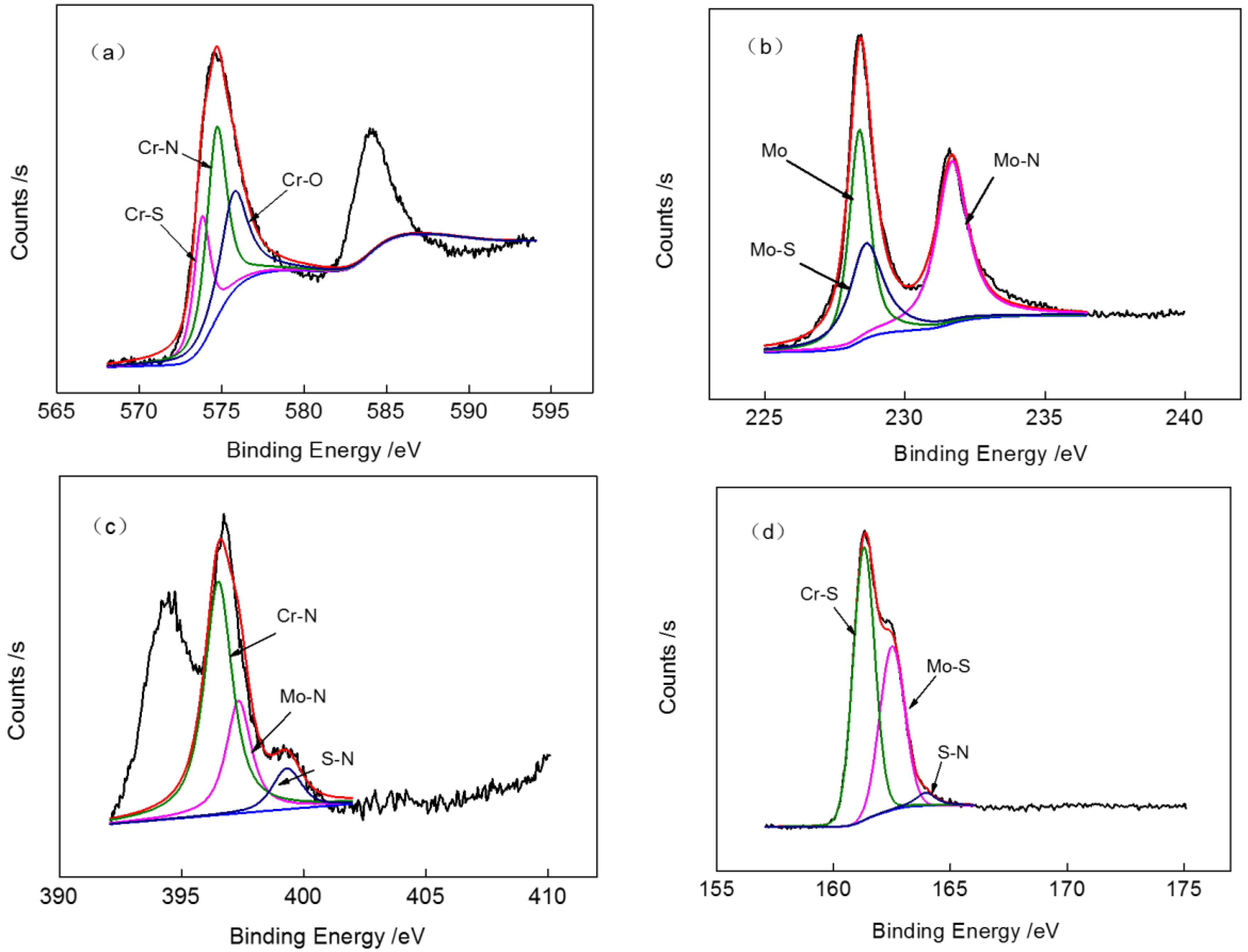
The X-ray photoelectron Spectroscopy (XPS) analysis results of the chemical valence states of CrMoN/MoS2 coatings are shown in Figure 3. The peaks of Cr2p3/2 were the compound of Cr–S, Cr–N and Cr–O, where the bonding energy was 574.4, 575.3 and 576.8 eV, respectively. The appearance of Cr–O may be attributed to surface oxide pollution. The peak of Mo emerged in the same place as the superposed peaks of Mo (228 eV) and Mo–S (229 eV). The peak of Mo–N also appeared where the bonding energy was 231.5 eV. The bonding energy of S 2p was 161.3 and 162.5 eV, which corresponded to Cr–S and Mo–S. In addition, S–N was also can be observed but not significantly, so it was not able to be analyzed in the XRD results.
3.3. Surface Morphologies
The scanning electron microscopy (SEM) micrographs of the Cr and CrMoN/MoS2 coatings are shown in Figure 4. It can be seen that the morphology of the CrMoN/MoS2 coating is entirely different from the Cr plating. The surface of the Cr plating is lamellar particles, while the CrMoN/MoS2 composite coating reveals a dense and smooth surface structure. The grains of the Cr plating are larger than those of the CrMoN/MoS2 composite coating.
The cross-section morphology of the Cr and CrMoN/MoS2 coatings are shown in Figure 5. It can be seen that the interface of the two coatings are all columnar crystal structures, the only difference being that the grain of the Cr plating is larger. The CrMoN/MoS2 coating is built up with two layers. On the bottom is a Cr/CrN transition layer, and on the top is a CrMoN composite layer. The sulfide particles heap together, layer by layer, on the top of the CrMoN/MoS2 composite coating, and the thickness of the surface sulfide layer is about 1 μm. Sulfurizing processing is a process of combination, dissociation and diffusion, in which the sulfide layer is formed by the absorption and deposition of sulfide particles. Under the bombardment of sulfur ions, parts of the sulfide layers are decomposed to sulfur ions or sulfur atoms, while the rest diffuses into the inner layer at high temperature. However, the diffusion speed of sulfur is limited and thus it only diffuses along the grain boundary and dislocates by short circuit diffusion. Therefore, the sulfide layer is thinner.
3.4. Nanoindentation
The nano-hardness test results of Cr plating and the CrMoN/MoS2 composite coating are listed in Table 3; all the results are the average values between 300 and 400 nm. It can be seen that the average nano-hardness and Young’s modulus of the CrMoN/MoS2 composite coating were 29.2 and 347.1, respectively, which are much higher than those of Cr plating (5.4 and 194.7, respectively). Therefore, the resistance of plastic deformation was enhanced. The reason for this can be analyzed as follows: (1) Fine grained strengthening. The refinement of the grains of the CrMoN/MoS2 composite coating created more dislocations at the grain boundaries, thus the size of the grains of the surface layer is less than 30 nm; (2) Symplastic growth. During the sulfurizing process, S atoms that come from the intracell can replace N atoms to form MoS2, which strengthens the inter-formational bonding force. Although the crystallization of MoS2 usually has a lower hardness, amorphous MoS2 has relatively high hardness, such as the MoS2–Ti composite coatings (trade-marked by Teer Coatings Ltd. as MoST™, Worcestershire, UK) that have shown excellent hardness and adhesion of the coatings, showing great improvements of wear-resistance properties in comparison with conventional hard coatings [12]. So, the relative high hardness of the CrMoN/MoS2 composite coatings may be due to the formation of the amorphous MoS2 in the coatings. CrN and MoN hard phases can stand the MoS2 soft phase, and the interphase interaction of hard and soft phases can improve the mechanical properties of the CrMoN/MoS2 composite coatings as well as enhance their antifriction and abrasive resistance.
3.5. Friction Behavior
Figure 6 depicts the friction coefficient curve under different static loads of piston ring-cylinder friction pairs with either Cr plating or CrMoN/MoS2 coating. It can be seen that these two kinds of friction coefficients with different coatings on piston ring-cylinder friction pairs both decreased as the load increased, and this result was not affected by error. When the load increased from 50 N to 170 N, the friction coefficient decreased sharply, while when the load increased from 170 to 400 N, the friction coefficient dropped more gently. In the friction process, when the load increases, friction surface asperities deformation occurs and the contact areas increase. Due to the two kinds of coatings, the piston ring shows a higher hardness and carrying capacity, and the ratio of the load increment is greater in proportion to the increment of shear force and contact area [13,14]. When the load changes from 50 to 400 N, the friction coefficient of the Cr electroplated piston ring decreases about 26%, while the piston ring with CrMoN/MoS2 coating decreasing about 40%. The friction coefficient of the CrMoN/MoS2 coating is lower than that of the Cr plating and, especially at a high load of 400 N, the anti-friction performance is obvious.
Figure 7 shows the wear weight loss of the piston ring-cylinder liner friction pairs with Cr electroplating and CrMoN/MoS2 coating. As is shown in the figure, the total weight loss of the two kinds of coated friction pairs increases with the increase of the load. The wear loss of the CrMoN/MoS2 coating on the piston ring-cylinder liner friction pair is significantly lower than that of the Cr friction pair. When the load is 50 and 170 N, the total weight loss increases more slowly. The total weight loss increases more obviously when the load exceeds 170 N. When the load is 400 N, the total weight loss of the Cr friction pair increases about 50%, while the CrMoN/MoS2 coating friction pair increases about 39%, showing a better wear resistance.
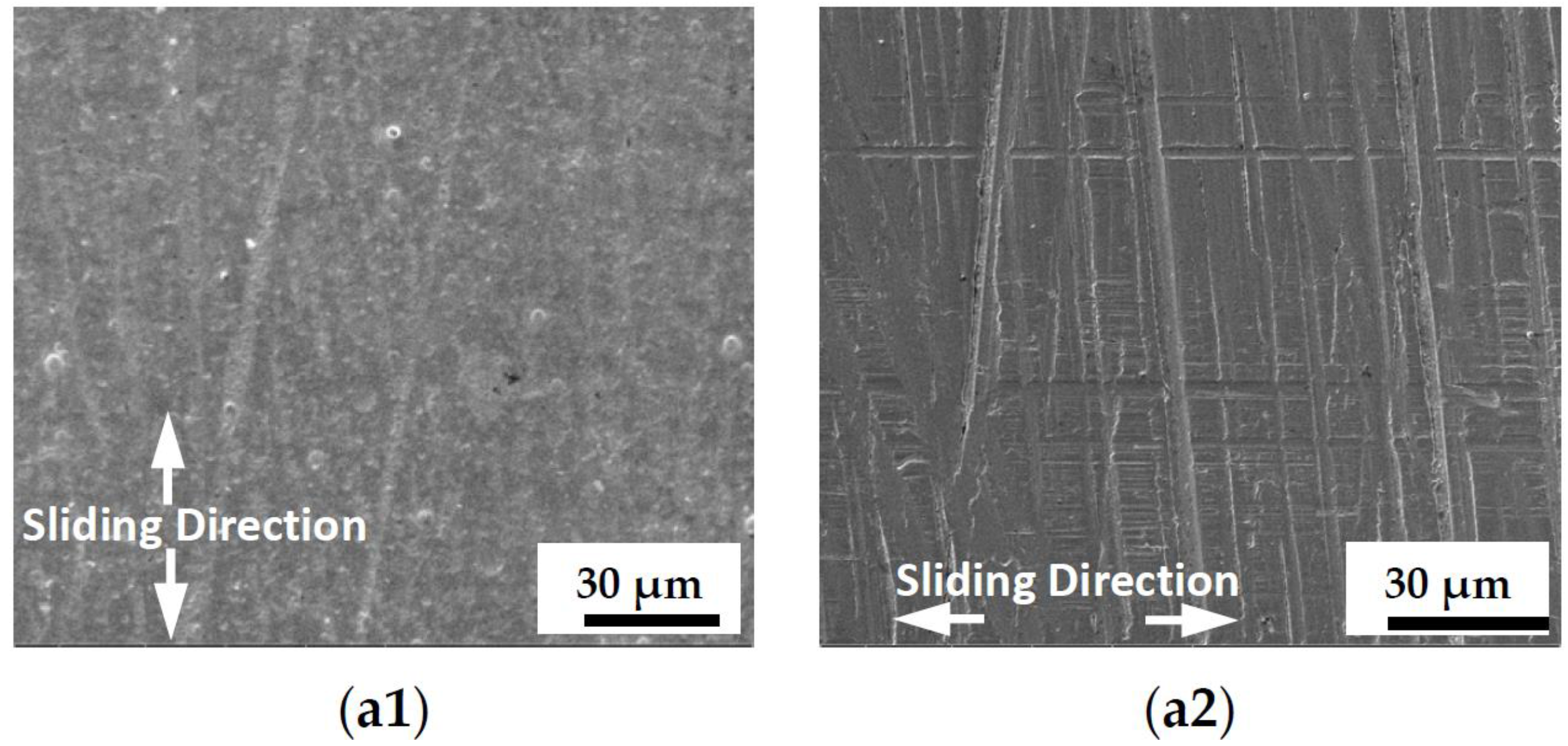
Figure 8 and Figure 9 depict the wear scar morphology of Cr and CrMoN/MoS2 coatings under different load conditions. From Figure 8, there is a slight furrow on the surface of the Cr plating of the piston ring due to the plough action of grinding, and some small and shallow scratches are on the cylinder liner surface. The wear mechanism of the Cr plated piston ring and cylinder liner is mainly abrasive wear (Figure 9a1,a2). The wear traces of abrasive wear on the piston ring and cylinder liner surface increase as the load increases (Figure 9b1,b2,c1,c2). The wear weight loss increases as the pressure in the contact surface increases. When the load increased to 400 N, there is serious abrasive wear and adhesive wear, caused by friction heat in the friction process. The wear mechanism of the piston ring transferred to abrasive wear and adhesive wear, as well as the cylinder liner.
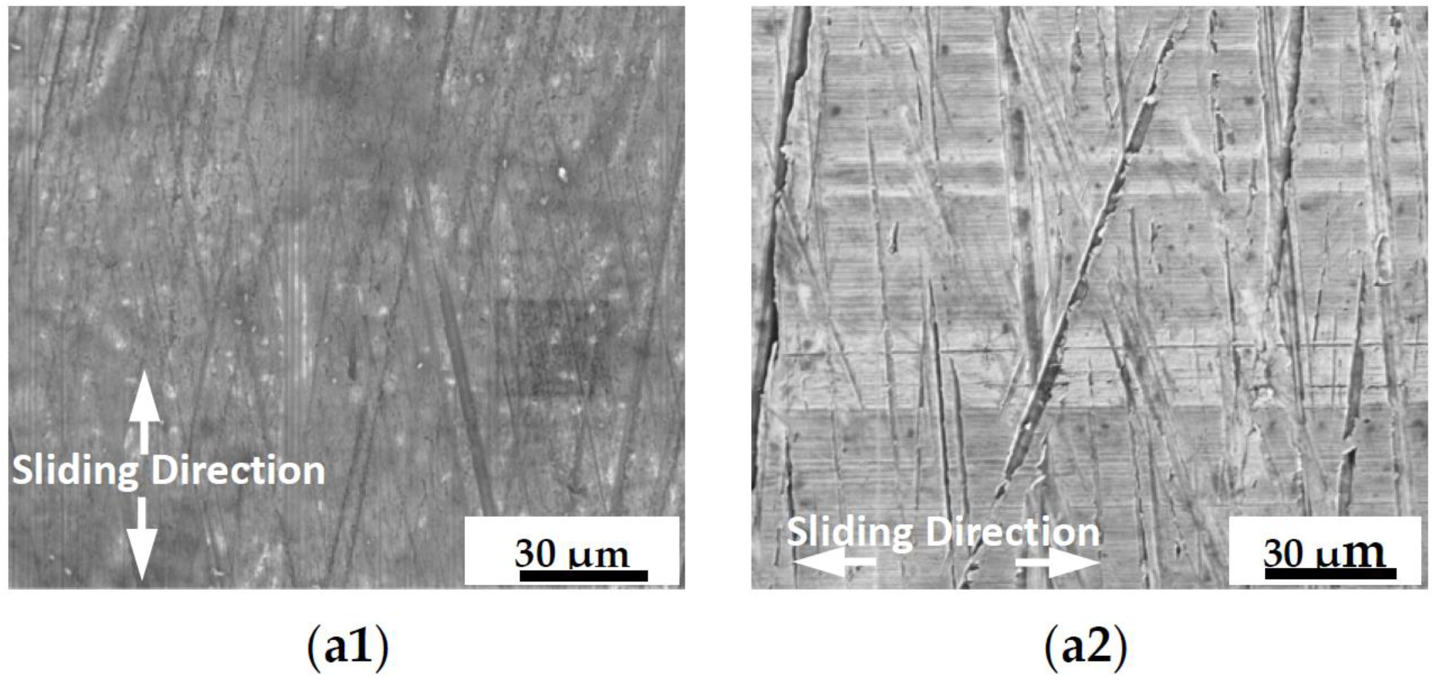
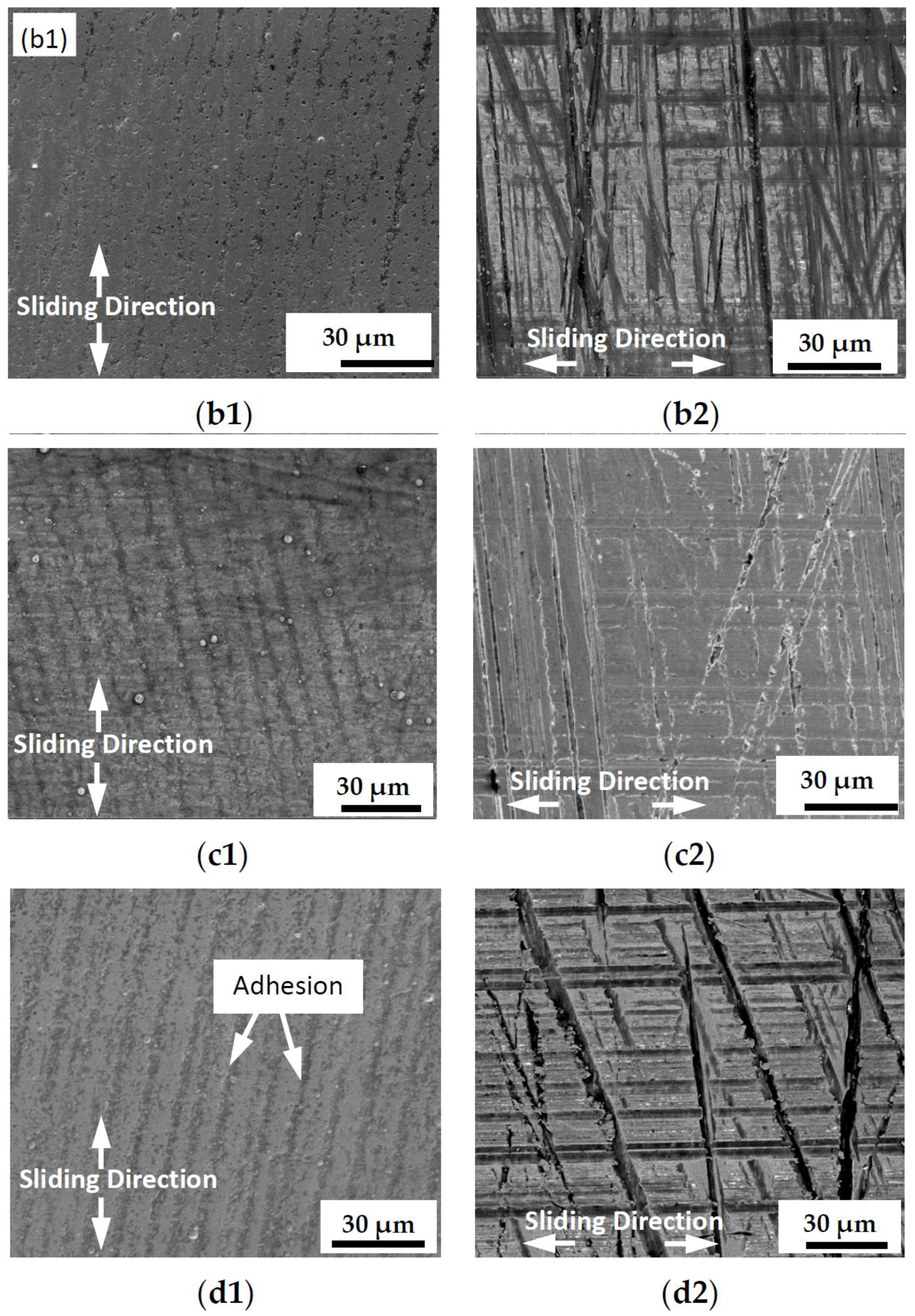
From Figure 9, it is known that the wear condition of the CrMoN/MoS2 friction pair is obviously better than Cr plating. There are only some slight furrows on the surface of the CrMoN/MoS2 piston ring at the load of 50 N, showing abrasive wear form (Figure 10a1,a2). The plough on the surface of the CrMoN/MoS2 piston ring and cylinder liner deepens as the load increases. When the load is 400 N, the wear mechanism is mainly abrasive wear, as well as some slight adhesive wear (Figure 10d1,d2). According to the transform film theory of self-lubricating composite coatings, a relative motion happened between two materials, and the adhesive wear caused by plastic deformation can exist under contact stress at high load, transferring from the piston surface to another surface easily, and thus forming a transfer film on the grinding surface after continuously reciprocating friction, adhesion and peeling.
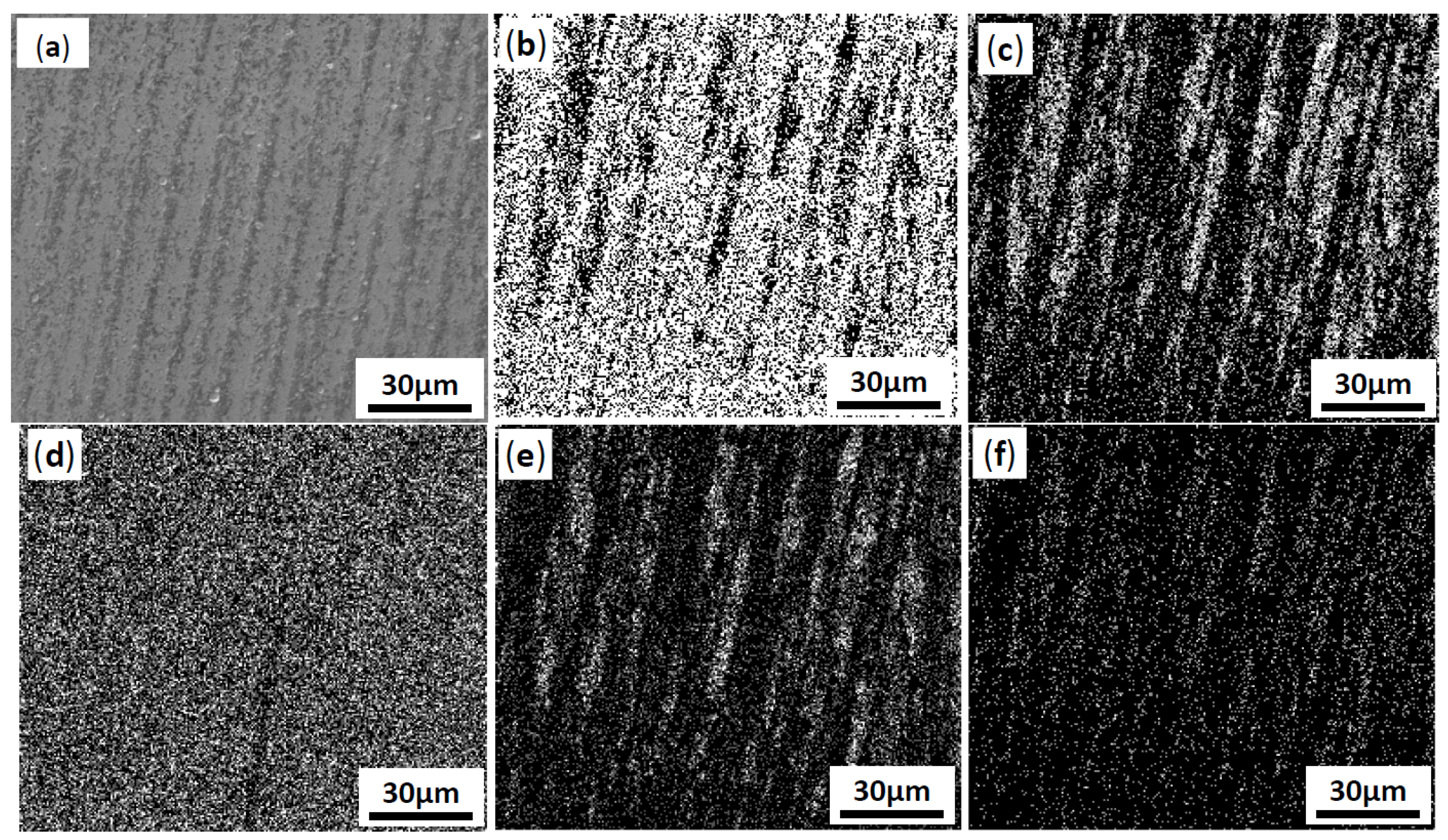
The Electron spectrometer (EDS) analysis result is shown in Figure 10. It can be seen that there are still S and Mo elements on the surface of the piston ring under the high load of 400 N. In the friction process, the solid lubricant film can reduce the direct contact of the micro convex body of the friction pair, which is easily transferred under high plastic stress, and adheres to the grinding cylinder liner, thus reducing wear and tear.
4. Conclusions
Close-field unbalanced magnetron sputtering and low temperature ion sulfurizing technology are combined to prepare CrMoN/MoS2 composite coatings. Based on the results of this study, we arrive at the following conclusions:
- (1)
- Compared with Cr plating, the CrMoN/MoS2 coating shows a dense and compact surface structure, and its grains are fine and granular. A composite phase structure was formed on the surface of the CrMoN/MoS2 composite coating after sulfurizing. The outer surface is MoS2 with antifriction and lubricant effects, and the subsurface is CrN and Mo2N with high hardness.
- (2)
- The average nano-hardness and Young’s modulus of the CrMoN/MoS2 composite coating was 29.2 and 347.1, respectively, which was much higher than those of Cr plating.
- (3)
- Under poor lubrication friction conditions, as the static load and frequency increases, the friction coefficient of both kinds of coating decreased; the friction coefficient of the CrMoN/MoS2 solid lubricating composite coating was lower than that of the Cr plating layer, and under high load conditions, the Cr electroplated friction pair wear amount is larger and the wear mechanism changed into complicated grinding abrasive wear and adhesive wear. The wear weight loss of the CrMoN/MoS2 composite coating was far below that of the Cr electroplated friction pair, showing superior antifriction and wear resistance performance.
Acknowledgements
This work was financially supported by the National Natural Science Foundation under Grant (No. 50901089) and National Key laboratory for remanufacturing under Grant (Project No. 9140C850207100C8506).
Author Contributions
For research articles with several authors, a short paragraph specifying their individual contributions must be provided. Zhihai Cai and Yuelan Di conceived and designed the experiments; Yuelan Di performed the experiments; Yuelan Di analyzed the data; Ping Zhang contributed reagents/materials/analysis tools; Yuelan Di wrote the paper.
Conflicts of Interest
The authors declare no conflict of interest.
References
- Liu, H. A Comprehensive Study on Nano-Lubricant in Piston Set and Cylinder Liner of Internal Combustion Engine for Heat Transfer and Lubrication Friction; Dalian University of Technology: Dalian, China, 2015. [Google Scholar]
- Nakasa, M. Engine friction overview. In Proceedings of the International Tribology Conference, Yokohama, Japan, 29 October–2 November 1995. [Google Scholar]
- Spearot, J.A. Friction, wear, health, and environmental impacts-tribology in the new millennium. Presented at the STLE Annual Meeting, Nashville, Tennessee, 22–26 May 2000. [Google Scholar]
- Li, Q.; Wang, X.C.; He, X.G.; Cai, Z.-H.; He, M. Wear Failure Mechanism of Cylinder Liner-Piston Ring Friction Pair for High Power Diesel Engines. China Surf. Eng. 2012, 25, 36–41. [Google Scholar] [CrossRef]
- Zhang, Q.M.; Liu, W.J. Wear performance of cast iron piston rings strengthened by laser. Chin. J. Met. 2006, 16, 447–452. [Google Scholar]
- Cai, Z.H.; Di, Y.L.; Zhang, P. Microstructure and tribological property of Cr/CrN nano-multilayer film deposited on piston ring. J. Shenyang Univ. Technol. 2011, 33, 375–381. [Google Scholar]
- Hao, Q.G.; Wang, Y.; Jia, X.S.; Zuo, X.W.; Chen, N.L. Dynamic compression behavior and microstructure of a novel low-carbon quenching-partitioning-tempering steel. Acta Metall. Sin. 2014, 27, 444–451. [Google Scholar] [CrossRef]
- Aouadi, S.M.; Gao, H.Y.; Martini, A.; Muratore, C. Lubricious oxide coatings for extreme temperature applications: A review. Surf. Coat. Tchanol. 2014, 257, 266–277. [Google Scholar] [CrossRef]
- Zhang, N.; Zhuang, D.M.; Liu, J.J.; Fang, X.D.; Guan, M.X. Wear mechanisms of ion-sulphurization layer on steel under dry conditions. Wear 2001, 247, 1–8. [Google Scholar]
- Wang, H.D.; Zhuang, D.M.; Wang, K.L.; Liu, J.-J. Comparative investigation on tribological properties of ion-sulfuration layers under dry friction. Tribol. Lett. 2002, 13, 55–61. [Google Scholar]
- Jensen, M.F.; Bǿttiger, J.; Reitz, H.H.; Benzon, M.E. Simulation of wear characteristics of engine cylinders. Wear 2002, 253, 1044–1056. [Google Scholar] [CrossRef]
- Renevier, N.M.; Fox, V.C.; Teer, D.G.; Hampshire, J. Coating characteristics and tribological properties of sputter-deposited MoS2 metal composite coatings deposited by closed field unbalanced magnetron sputter ion plating. Surf. Coat. Technol. 2000, 127, 24–37. [Google Scholar] [CrossRef]
- Guo, C.; Chen, J.M.; Zhou, J.S.; Zhou, H.D. Microstructure and tribological properties of TiAg intermetallic compound coating. Appl. Surf. Sci. 2011, 257, 10692–10698. [Google Scholar] [CrossRef]
- La, P.Q.; Ma, J.Q.; Zhu, Y.T.; Valiev, R.Z. Dry–sliding tribological properties of ultrafine-grained Ti prepared by severe plastic deformation. Acta Mater. 2005, 53, 5167–5173. [Google Scholar] [CrossRef]
Figure 1.
The contact mode and movement of piston ring and cylinder liner.
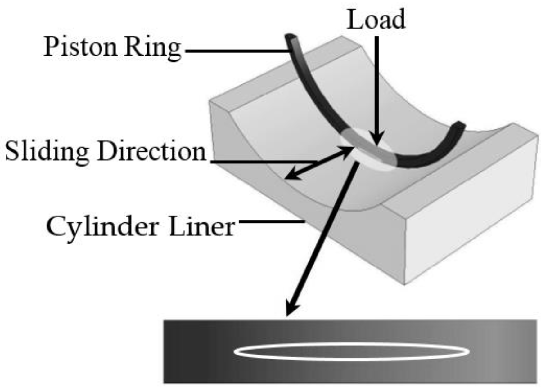
Figure 2.
XRD patterns of CrMoN/MoS2 composite coating.
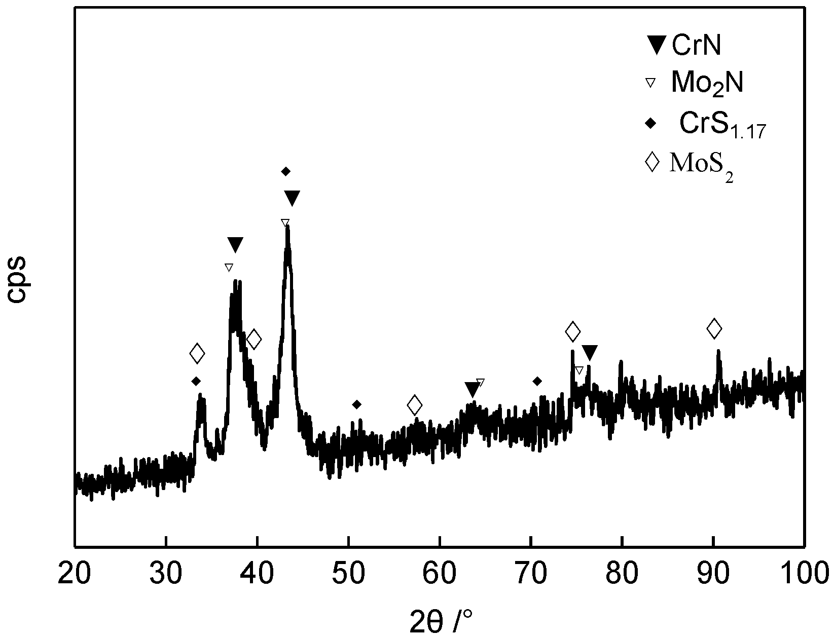
Figure 3.
X-ray photoelectron Spectroscopy (XPS) analysis of CrMoN/MoS2 coatings (a) Cr2p; (b) Mo3d; (c) N1s; (d) S2p.
Figure 3.
X-ray photoelectron Spectroscopy (XPS) analysis of CrMoN/MoS2 coatings (a) Cr2p; (b) Mo3d; (c) N1s; (d) S2p.

Figure 4.
Surface morphologies of Cr plating (a) and the CrMoN/MoS2 composite coating (b).
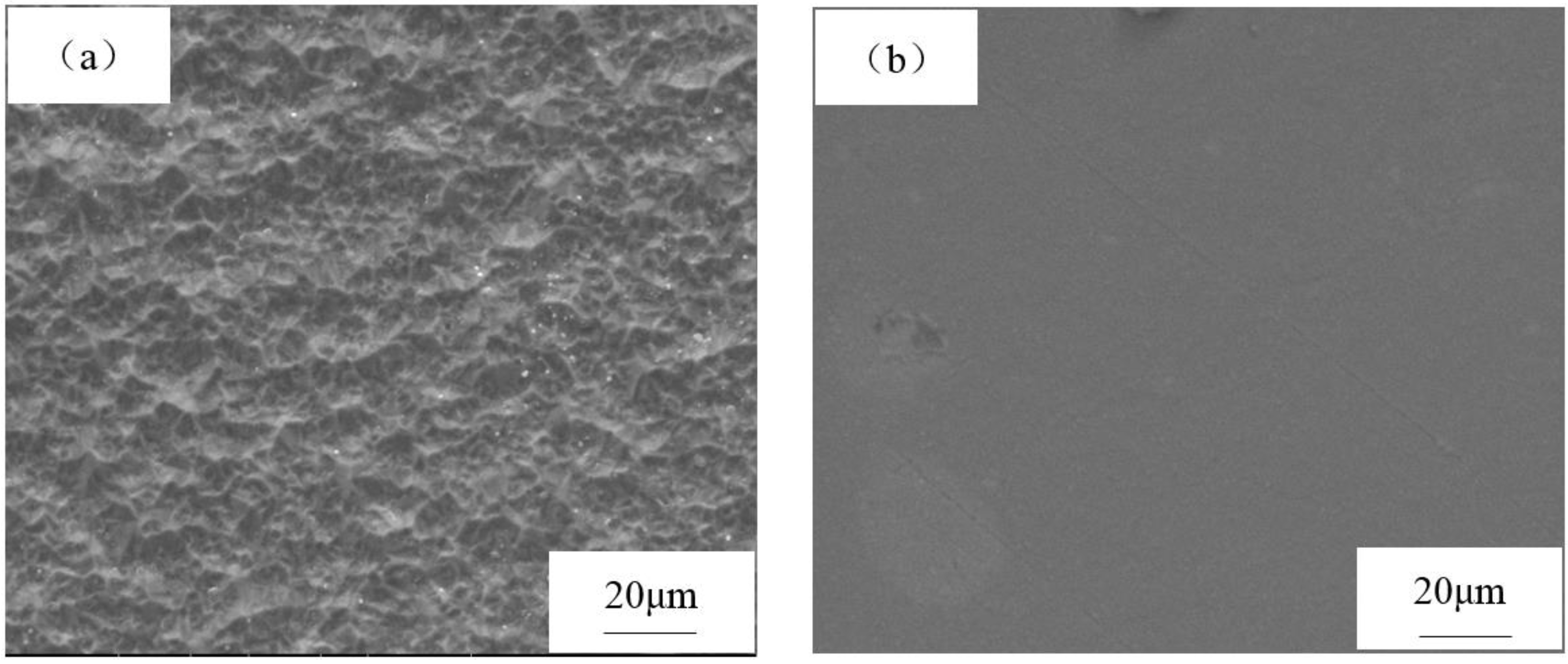
Figure 5.
Cross-section morphology of Cr plating (a) and the CrMoN/MoS2 composite coating (b).

Figure 6.
The friction coefficient of two kinds of coatings with load changing.
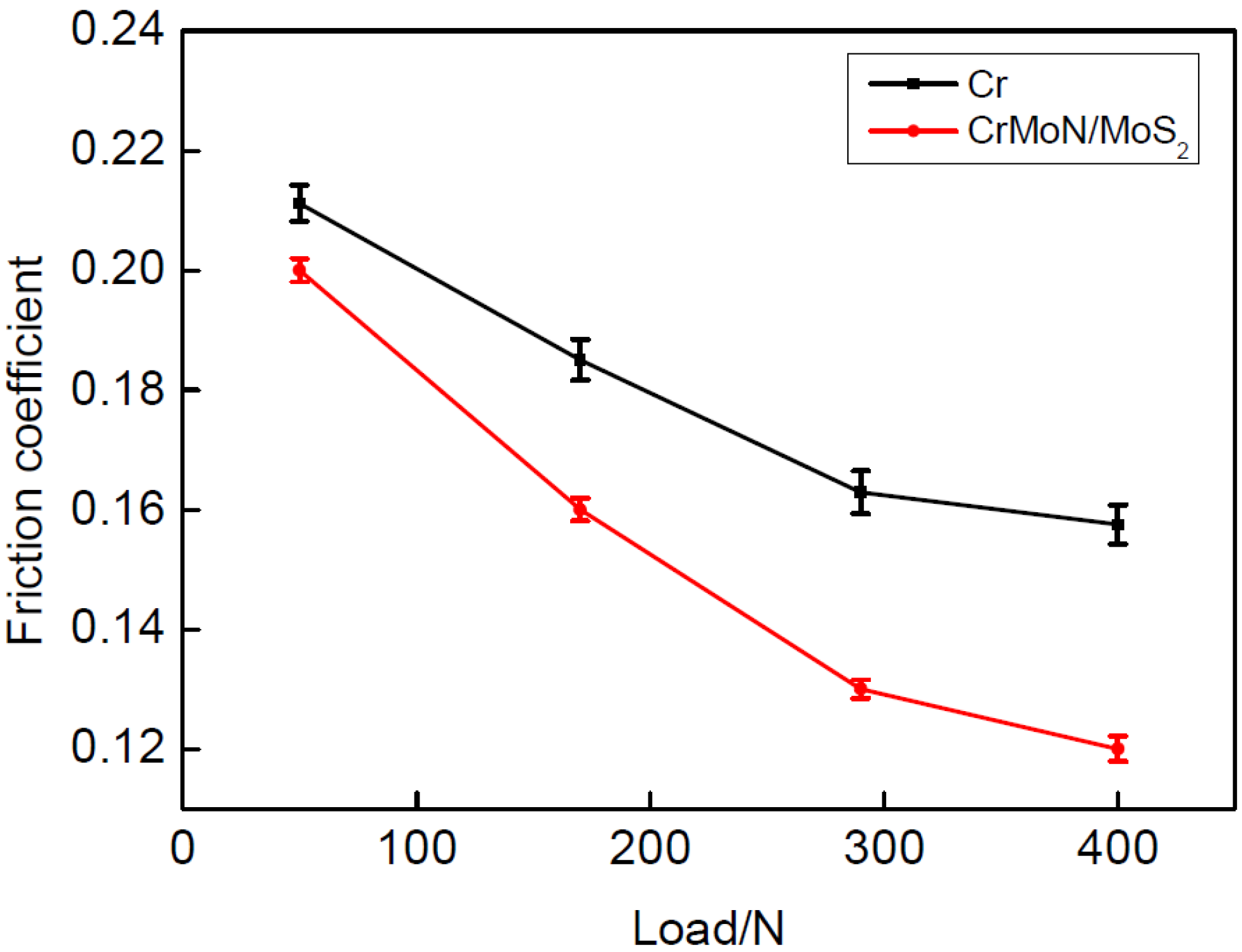
Figure 7.
Wear weight loss of friction pairs under different load conditions.
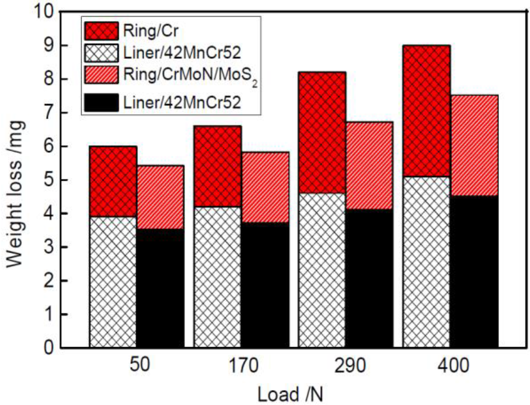
Figure 8.
The morphology of the wear scar of the Cr electroplated friction pair under different static loads. (a1) Piston ring, 50 N; (a2) Cylinder, 50 N; (b1) Piston ring, 170 N; (b2) Cylinder, 170 N; (c1) Piston ring, 290 N; (c2) Cylinder, 290 N; (d1) Piston ring, 400 N; (d2) Cylinder, 400 N.
Figure 8.
The morphology of the wear scar of the Cr electroplated friction pair under different static loads. (a1) Piston ring, 50 N; (a2) Cylinder, 50 N; (b1) Piston ring, 170 N; (b2) Cylinder, 170 N; (c1) Piston ring, 290 N; (c2) Cylinder, 290 N; (d1) Piston ring, 400 N; (d2) Cylinder, 400 N.

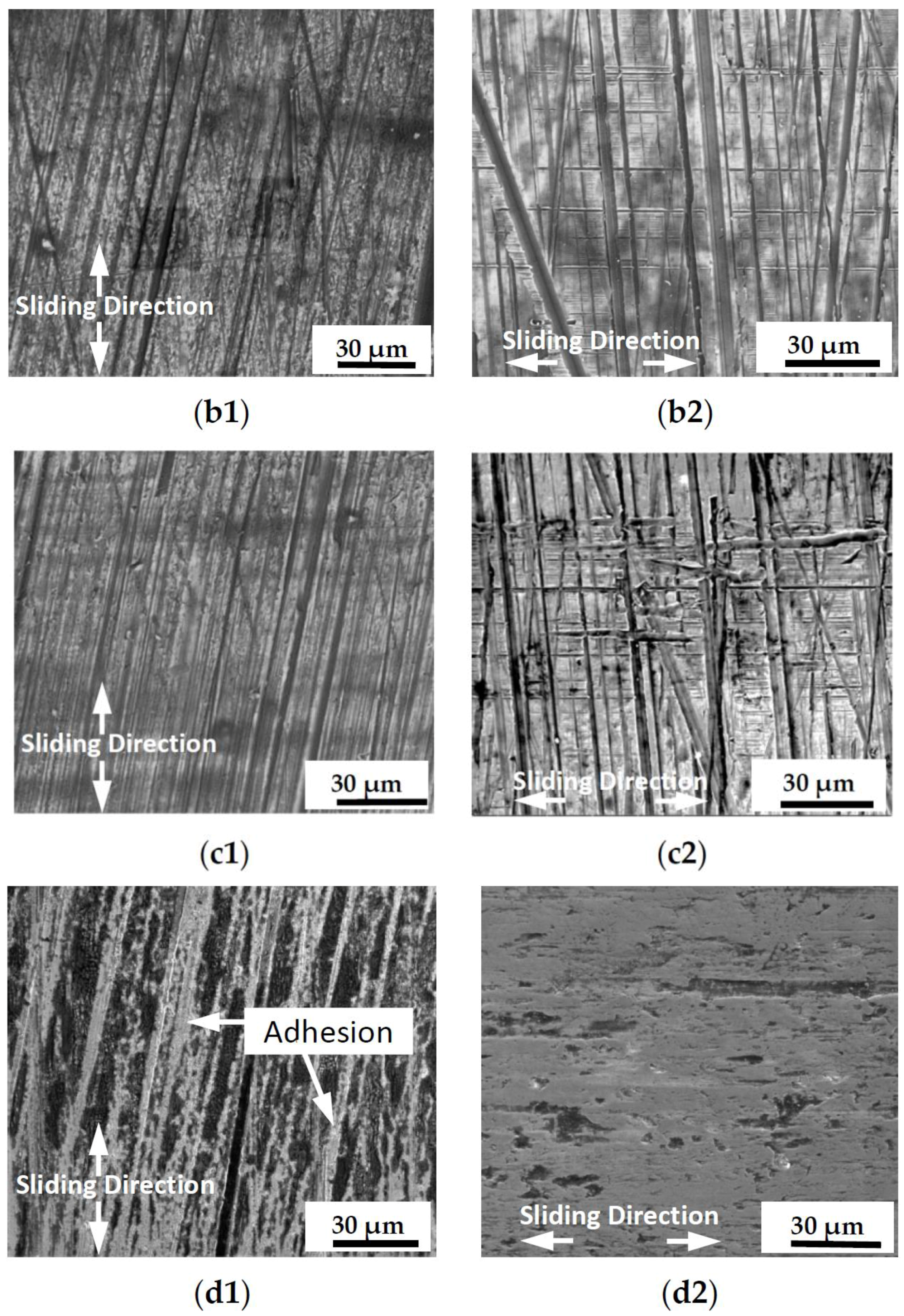
Figure 9.
The morphology of the wear scar of the electroplating Cr friction pairs under different static loads. (a1) Piston ring, 50 N; (a2) Cylinder, 50 N; (b1) Piston ring, 170 N; (b2) Cylinder, 170 N; (c1) Piston ring, 290 N; (c2) Cylinder, 290 N; (d1) Piston ring, 400 N; (d2) Cylinder, 400 N.
Figure 9.
The morphology of the wear scar of the electroplating Cr friction pairs under different static loads. (a1) Piston ring, 50 N; (a2) Cylinder, 50 N; (b1) Piston ring, 170 N; (b2) Cylinder, 170 N; (c1) Piston ring, 290 N; (c2) Cylinder, 290 N; (d1) Piston ring, 400 N; (d2) Cylinder, 400 N.


Figure 10.
Element distribution of wear surface of the CrMoN/MoS2 piston ring under a load of 400 N. (a) Wear surface; (b) Cr; (c) N; (d) O; (e) Mo; (f) S.
Figure 10.
Element distribution of wear surface of the CrMoN/MoS2 piston ring under a load of 400 N. (a) Wear surface; (b) Cr; (c) N; (d) O; (e) Mo; (f) S.


Table 1.
Friction test condition.
| Load/N | Frequency/Hz | Temperature/°C | Time/s | Stroke/mm |
|---|---|---|---|---|
| 50 | 20 | 100 | 7200 | 4 |
| 170 | ||||
| 290 | ||||
| 400 |
Table 2.
The component analysis result of coatings.
| Coatings | As Deposited | Sulfurized | |||
|---|---|---|---|---|---|
| Cr | Mo | Cr | Mo | S | |
| Cr0.35Mo0.65N | 17.07% | 33.27% | 14.93% | 28.17% | 6.9% |
Table 3.
The nano-hardness test results.
| Coatings | H/GPa | E/GPa | H3/E2/Gpa | Dmax/NM |
|---|---|---|---|---|
| Cr | 5.4 | 194.7 | 0.004 | 1063.453 |
| CrMoN/MoS2 | 29.2 | 347.1 | 0.207 | 1027.832 |
© 2017 by the authors. Licensee MDPI, Basel, Switzerland. This article is an open access article distributed under the terms and conditions of the Creative Commons Attribution (CC BY) license (http://creativecommons.org/licenses/by/4.0/).
Share and Cite
MDPI and ACS Style
Di, Y.; Cai, Z.; Zhang, P. The Tribological Performance of CrMoN/MoS2 Solid Lubrication Coating on a Piston Ring. Lubricants 2017, 5, 13. https://doi.org/10.3390/lubricants5020013
AMA Style
Di Y, Cai Z, Zhang P. The Tribological Performance of CrMoN/MoS2 Solid Lubrication Coating on a Piston Ring. Lubricants. 2017; 5(2):13. https://doi.org/10.3390/lubricants5020013
Chicago/Turabian StyleDi, Yuelan, Zhihai Cai, and Ping Zhang. 2017. "The Tribological Performance of CrMoN/MoS2 Solid Lubrication Coating on a Piston Ring" Lubricants 5, no. 2: 13. https://doi.org/10.3390/lubricants5020013
Note that from the first issue of 2016, this journal uses article numbers instead of page numbers. See further details here.