Film Thickness and Friction Relationship in Grease Lubricated Rough Contacts
by
 , and
, and
David Gonçalves
1,* ,
,
António Vieira
2,
António Carneiro
2, 
Armando V. Campos
3 and
Jorge H. O. Seabra
2 1
Instituto de Ciência e Inovação em Engenharia Mecânica e Engenharia Industrial, Universidade do Porto, Campus FEUP, Rua Dr. Roberto Frias 400, 4200-465 Porto, Portugal
2
Faculdade de Engenharia da Universidade do Porto, Rua Dr. Roberto Frias s/n, 4200-465 Porto, Portugal
3
Instituto Superior de Engenharia do Politécnico do Porto, Rua Dr. António Bernardino de Almeida 431, 4200-072 Porto, Portugal
*
Author to whom correspondence should be addressed.
Lubricants 2017, 5(3), 34; https://doi.org/10.3390/lubricants5030034
Submission received: 30 June 2017
/
Revised: 27 July 2017
/
Accepted: 3 August 2017
/
Published: 17 August 2017
(This article belongs to the Special Issue Lubricating Greases 2017)
Abstract
:The relationship between the film generation and the coefficient of friction in grease lubricated contacts was investigated. Ball-on-disc tests were performed under different operating conditions: entrainment speed, lubricant temperature and surface roughness. The tests were performed with fully formulated greases and their base oils. The greases were formulated with different thickener types and also different base oils natures and viscosities. Film thickness measurements were performed in ball-on-glass disc tests, and Stribeck curves were measured in ball-on-steel disc tests with discs of different roughness. The role of the thickener and the base oil nature/viscosity on the film thickness and coefficient of friction was addressed and the greases’ performance was compared based on their formulation.
1. Introduction
In the last years, considerable advances in the grease lubrication field have been reached. Although the elasto-hydrodynamic (EHD) theory describes particularly well the fully flooded oil lubricated contacts behaviour, the same does not apply to lubricating greases. The mechanisms are not fully understood specially in what concerns the thickener role and the way the active lubricant is fed to the contacts.
Due to a growing interest in the topic over the last decades, a few generalized conclusions regarding grease lubrication have been achieved and are generally accepted. It is known that grease lubricated rolling bearings operate under starved conditions during the majority of their lives. After a churning phase where the grease in excess is pushed to the sides of the rolling contacts, it is believed that the contacts are fed by oil bleeding from the grease in the sideways by low shear action, although the grease (thickener plus base oil) might also enter the contact through a feed and loss mechanism.
In what concerns the lubricant film formation, it was already observed that both the oil released from the grease and the thickener lumps cross the EHD contact, contributing to increasing the film thickness [1,2,3]. It was also found that the higher the base oil viscosity and/or thickener content, the higher is the film thickness [4]. Moreover, other studies suggest that under fully flooded conditions, the grease generates a thicker film than its base oil [1,2,5,6]. The difference was attributed to the base oil viscosity but also the thickener type and its content [4], although the opposite relationship is generally observed in starved conditions.
Furthermore, Cann et al. [7] has used ball-on-disc interferometry measurements to show that the grease’s film thickness was actually composed of static film (a residual layer adsorbed on the surfaces, mainly composed by sheared thickener material) and a dynamic film resultant from the elasto-hydrodynamic effect. Residual films of thickness around 6 to 80 nm were found, consisting of significant amounts of thickener [7]. Thus, since the thickener will not enter the contact at higher speeds being pushed to the side, the dynamic film could be calculated using the standard EHD oil-film thickness equations, assuming the base oil is the active lubricant in the contact [8].
However, other authors have found that, in fully flooded conditions, the film thickness and coefficient of friction produced by the oil released from the grease (“bled oil” or “bleed-oil”) is much closer to the greases’ film thickness [9,10,11], when compared to the base oils’. This was attributed to the fact that the oil released from the grease under static or dynamic conditions can actually contain thickener elements and additives that might change the properties of the original base oil [11,12,13].
More recently, the thickener role influence on the film formation was addressed. It was found that under low to moderate speeds, the thickener material which enters the contact contributes to the film thickness in fully flooded grease lubricated contacts [14,15,16,17,18]. This allowed for a better understanding on the mechanisms which rule grease lubrication. Furthermore, by performing film thickness measurements in specially designed rolling bearings a correlation between the single ball-on-disc results to full rolling bearing tests was found [15,16].
The traction behaviour of lubricating oils is well documented [19,20,21,22]. It is known that the traction coefficient depends on the low shear viscosity, the limiting shear modulus and the limiting shear stress that the lubricant can withstand [19,21]. In the case of grease lubrication, its friction behaviour is poorly studied and frequently attributed to the base oil.
Although a lot of work has been done regarding the film thickness of grease lubricated contacts, there are very few published works related to friction. Once again, it is frequent to describe the grease behaviour based on the properties of the base oil. Still, a few authors claim that this assumption leads to wrong predictions [10,12,13,23,24,25], since the properties of the active lubricant at the contact inlet might be considerable different from those of the original base oil that the grease was formulated with (due to thickener, additives, etc.). Therefore, it is very hard to predict the correct lubrication regime, if the active lubricant is unknown.
The aim of this work is to analyse the relationship between the coefficient of friction and the lubrication regime of grease lubricated contacts, under fully flooded conditions.
2. Materials and Methods
2.1. Tested Greases
Four greases were tested in this work: CaM, ClayM, CaLiM and PPAO. Their names reflect their different formulations:
- CaM is formulated with anhydrous calcium thickener (8.5 wt % of Ca) and a base oil of mineral nature (M);
- ClayM is formulated with an inorganic Clay (7.3 wt %) as thickener and a mineral base oil (M);
- CaLiM is formulated with acethic lithium azelaic stearic sarcosylic calcium (17.1 wt % of CaLi thickener) and a base oil of mineral nature (M);
- PPAO is formulated with polypropylene thickener (14.5 wt % of PP) and a base oil of synthetic nature (poly-alpha-olefin—PAO).
The greases are all fully formulated although the actual additive package is unknown. All the greases are NLGI grade 2, although the actual values of worked penetration are not available (standard classification of lubricating grease established by the National Lubricating Grease Institute—NLGI).
2.2. Base Oils
The dynamic viscosities of the base oils are shown in Figure 1. These viscosities were measured in a Sine-wave Vibro Viscometer SV-10 (A & D Company, Tokyo, Japan) from 100 to 40 C.
Analysing Figure 1, it is clear that at 40 C, the viscosities of the base oils of greases CaM and ClayM are very close, although higher for ClayM. The base oil’s viscosity of grease PPAO is the smallest out of all of the base oils. As the temperature increases, their viscosities get closer, but, at 80 C, the differences in viscosity are still relevant and, hence, should greatly influence the film formation. At 100 C, the viscosities of all the base oils are now much closer and, therefore, at 100 C their differences should be much less relevant.
2.3. Thickener Morphology
In order to obtain its thickener, a sample of each grease was dissolved in petroleum ether by means of an ultrasonic device (Bandelin Sonorex Super RK 106, Berlin, Germany). The obtained solution was filtered through an 8 m mesh paper filter by the action of a vacuum pump and then kept in the oven at 50 C for at least 24 h, in order to ensure the evaporation of the residual ether from the filter. In the end, solid thickener material is obtained on the filter which can be observed by Scanning Electron Microscopy (SEM). This is not a standard method, and it is not optimal since the thickener matrix might get destroyed/collapse in the process [14]. Still, since it is not possible to observe wet grease samples using SEM operating under a high vacuum environment, this solution was used to investigate the thickener morphology only.
The analysis of the grease micro-structure was performed with a scanning electron microscope (FEI Quanta 400FEG ESEM—high vacuum, FEI, Thermo Fisher Scientific, Waltham, MA, USA), using secondary electrons detector. After being excited by the primary electron beams, the atoms of the surface will emit the secondary electron beam. These secondary electrons will be detected and an interpretable image of the surface’s topography is produced. All samples were covered with a very thin carbon film in order to protect the samples and avoid their degradation when using a higher energy electron beam to excite the surface and, thus the image quality is highly improved. The image’s contract is mainly determined by the sample’s morphology.
In Figure 2, the thickener morphology of greases CaM, ClayM, CaLiM and PPAO is shown.
The morphology of the thickeners of greases CaM and CaLiM is very similar. A fibre entanglement is observed where long and relatively thin fibres are entangled with each other in a porous matrix. In most of the soap based greases, the soap is presented as fibres or ribbons varying in size and length, from a few microns up to one hundred [26]. In the case of the CaM and CaLiM, the fibre/ribbons diameter vary from ≈0.030 to 0.200 m and are generally larger for grease CaM.
The PP thickener morphology of grease PPAO shows short and thick polymer elements randomly distributed in a dense matrix. Despite being hard to measure the diameter of such elements, their dimensions vary from ≈0.2 up to 1.2 m being considerably larger than the usual soap fibres.
The morphology of the clay thickener is very hard to distinguish. Due to insufficient oil/thickener separation, it seems that thickener material is still blended with oil and therefore it is hard to separately distinguish the thickener elements.
2.4. Film Thickness Measurement Procedure
Produced by PCS Instruments (London, UK), the EHD2 equipment is capable of measuring the lubricant film thickness over different configurations (ball or roller-on-disc), over a wide range of load (max. 50 N), speed (1 mm/s to 4 m/s), temperature and slide-to-roll ratio. The space layer interferometry method is used to measure very thin lubricant films with a 1 nm resolution, according to the setup shown in Figure 3. A very bright light source is directed towards the contact between the ball and the disc. Part of this light is reflected from the underside of the disc to the spectrometer, while the other part crosses the lubricant film and its reflected back from the steel ball. An interference image is then produced, from the interference of the two light beams which have travelled different distances. From that interference image, it is possible to compute the lubricant’s film thickness.
The test conditions are shown in Table 1. Before each test, a heat period of 30 min was applied to ensure the temperature stabilization. After this period, the space layer thickness was measured at the disc track radius, without any lubricant between the ball and the disc to set the zero and trigger point. The entrainment speed was then ramped up 3 times ranging from ≈0.01 to 2 m/s at constant slide-to-roll ratio, and a combined curve of the three measurements was created. The entrainment speed and slide-to-roll ratio (SRR) are defined according to Equations (1) and (2), respectively:
The fully flooded condition was ensured using a grease scoop, which forced the grease back into track. The temperature deviation at each ramp up was inferior to ±2 C from the average. An average of the three measurements for each grease was calculated.
2.5. COF Measurement Procedure
The Stribeck curves are generally measured under controlled temperature, constant load and constant SRR, while varying the entrainment speed. In order to reach lower specific film thickness and get closer to boundary lubrication, a series of steel discs were ground to a specific roughness value. The properties of the rougher discs are shown in Table 2.
Three Stribeck curves were measured under constant SRR (5%), at different operating temperatures, according to the procedure shown in Table 3. An average curve was then calculated from the three measurements. The test temperatures were chosen in order to measure the COF under different lubrication regimes. An SRR of 5% was selected because it is a reference value for rolling bearings. Once again, fully flooded conditions were ensured by using a grease scoop.
3. Film Thickness Results
The results of the central film thickness measurements are shown in Figure 4, Figure 5, Figure 6 and Figure 7, comparing each grease with the corresponding base oil.
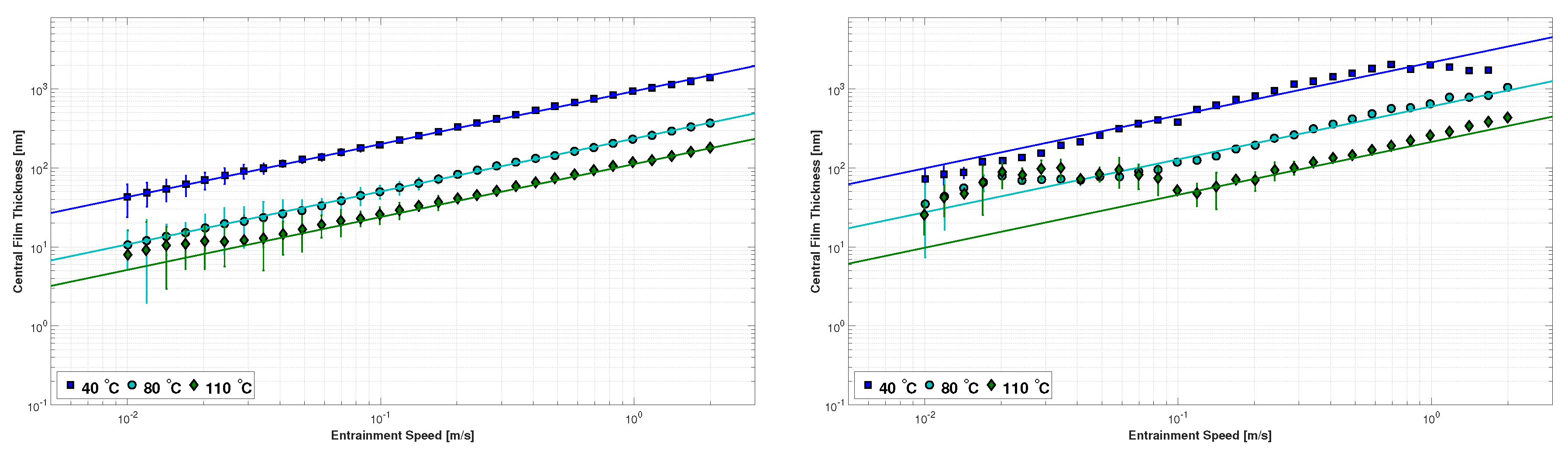
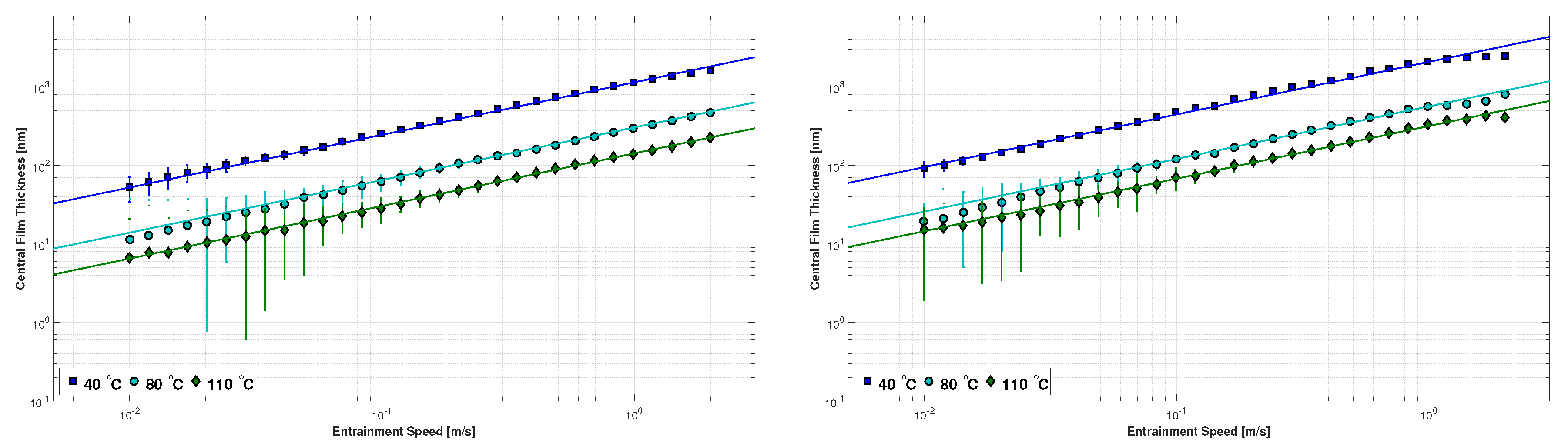
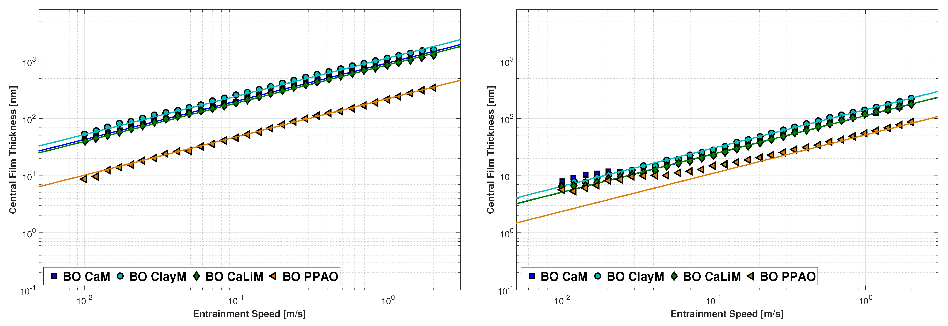
Regarding the base oils, it is clear that the film thickness increases linearly (in log scale) with the entrainment speed. This is due to a more pronounced hydrodynamic effect, promoted by increasing speed. It is also possible to observe the decrease of the film thickness as the temperature increases due to the decrease of the operating viscosity.
As for the greases, under the same rolling speed range (0.010 to 2 m/s) and low operating temperature (40 C), they behave very similar to the oils, showing a linear increase of the film thickness as the speed increases. The inlet shear heating effect is observed at low temperature and high speeds for greases CaM and ClayM, but not for the other greases.
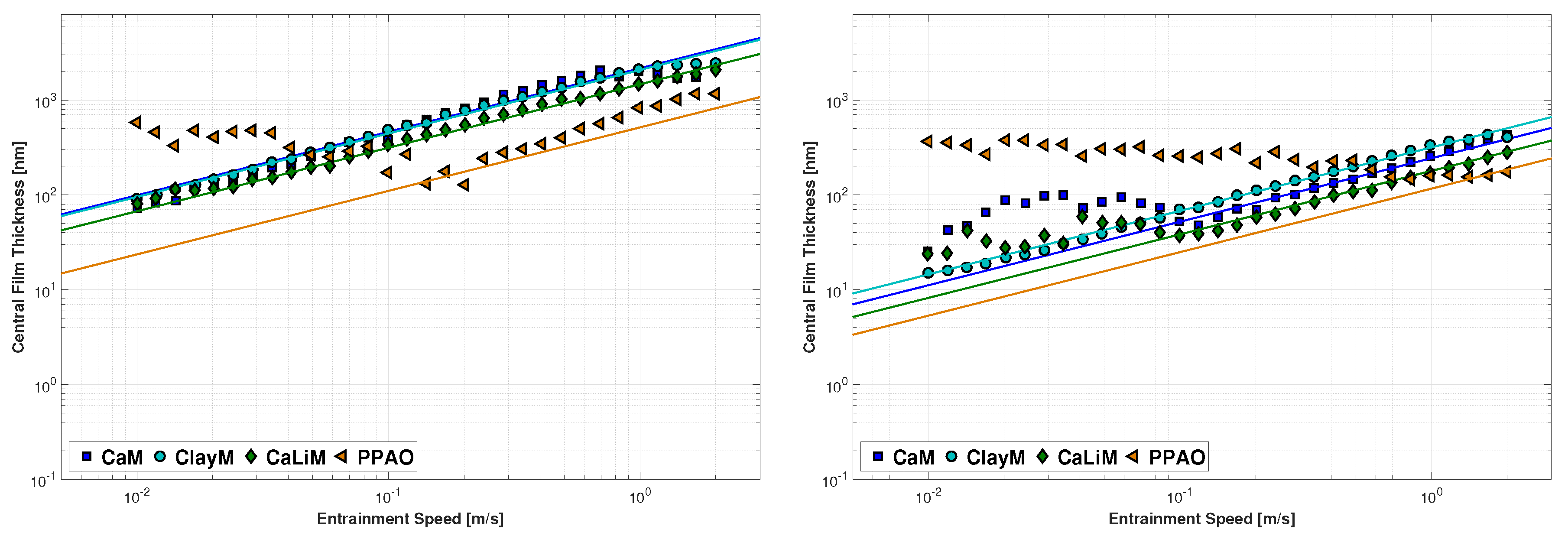
However, under low rolling speeds, the behaviour of greases is different from their base oils specially at higher operating temperatures. Below a certain transition speed (or even, transition film thickness), the decrease of the entrainment speed no longer promotes a decrease in the film thickness but actually the opposite. At low entrainment speeds, the film thickness of the greases increases with decreasing rolling speed, albeit slightly.
This phenomenon does not happen at the same temperature or speed for all greases and the film thickness increment in this region at low speeds is also different between greases. Actually, under the tested speed range (0.010 to 2 m/s) it did not happen at all for grease ClayM at any temperature. For greases CaM and CaLiM, it is starts to occur at 80 C but it is particularly important at 110 C. On the other hand, for the polymer grease PPAO, the phenomenon is observed at all temperatures. The higher the temperature, the longer this region is in terms of entrainment speed.
The transition speed seems to increase with temperature, and, the film thickness increase below that speed seems to be unaffected by temperature and therefore, it should not depend on viscosity. As observed before by other authors, this phenomenon is caused by the passage of thickener material through the contact which contributes to support the load and separate the surfaces, by increasing the film thickness [15,16,17,18,27]. That transition film thickness is reached at higher speeds when the temperature increases because it should be easier for the thickener to enter the contact since the greases’ consistency is reduced.
Therefore, in this region at low speeds, the film thickness is controlled by the thickener and not the base oil, and thus, it does not change by increasing temperature. If the film thickness increase is promoted by the amount of thickener or its morphology, it is unknown, but there seems to be a correlation between the thickener elements’ size and the film thickness in this region [17]. In fact, analysing the pictures shown in Section 2.3, it is possible to verify that the film thickness in the low speed region is of the same order of magnitude as the thickener elements’ diameter. Thus, thickener elements of higher diameter should produce higher film thickness in the low speed region.
In Figure 4, Figure 5, Figure 6 and Figure 7, it is also possible to observe that the greases always produce higher film thickness than the base oils in fully flooded conditions, both in the low speed and the high speed regions. The ratio between the film thickness of grease and base oil , in the high speed region where both show a linear increase of the film thickness with speed, is shown in Table 4.
Comparing the film thickness of the base oils, the following order was found:
which shows that three mineral oils are very similar. However, it was unexpected to find that the base oil (BO) of grease CaM shows higher film thickness than the BO of grease CaLiM, despite showing smaller viscosity. Figure 8 shows this comparison at 40 and 110 C.
Figure 9 shows the same comparison but now for the film thickness of the greases. Under low temperatures and high speed regions, the following order was found:
Comparing the film thickness of the greases under high temperatures and low speed regions, the following order was found:
which shows that, depending on the operating conditions, the film thickness of the grease can be very different and not be singularly dependent on the base oil viscosity, as generally attributed.
4. Coefficient of Friction Results and Discussion
4.1. Film Thickness Measurements Correction
In order to better understand the COF results it is necessary to know the lubrication regime along the test.
The film thickness curves shown in Section 3 were measured under the same operating conditions (load, temperature, contact geometry, scoop), but for a steel ball on glass disc contact instead of the steel ball on a steel disc used for the COF measurements. To be able to compare the results from both tests, it is necessary to correct the film thickness curves of the steel-glass contact () to the steel-steel contact (). This procedure was performed using Hamrock and Dowson’s Equation [28]. Calculating the ratio between two film thickness equations for the same lubricant and same contact geometry, the following expression is reached:
If the operating conditions of both tests are the same such that and , the difference between the tests is related to the surfaces’ materials only. Therefore, the previous expression results in Equation (7):
Which means that the film thickness of the COF tests () should be around 5% smaller than the film thickness measured with a steel ball on glass disc contact (). Hence, the film thickness of the steel ball on steel disc friction tests can quickly be estimated. A similar procedure has been reported earlier by De Laurentis et al. [27].
4.1.1. Specific Film Thickness
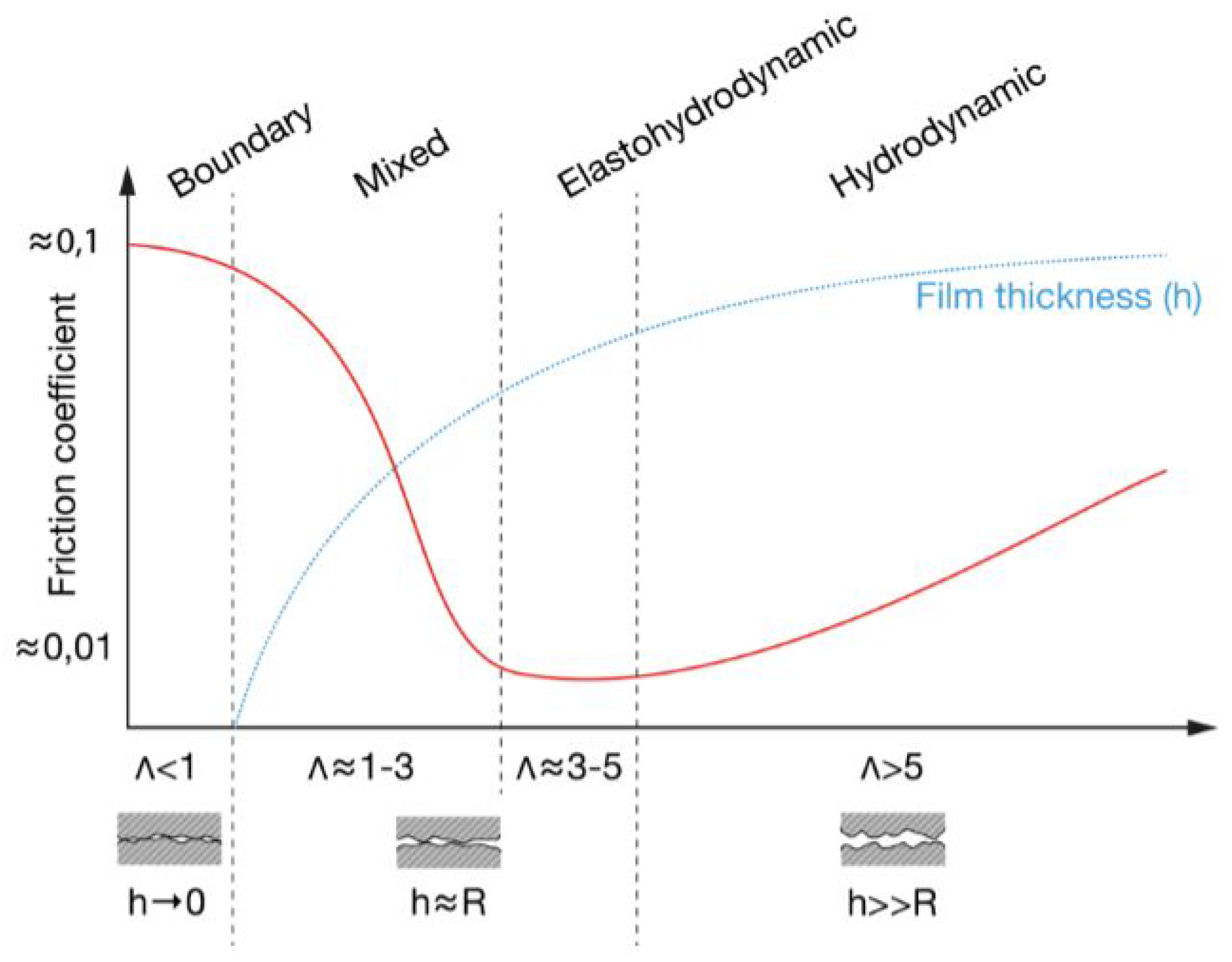
The concept of specific film thickness (), introduced by Tallian [29] in 1967, is important to identify which lubrication regime the mechanism is running into. Being a single ball-on-disc contact, the contact between a rolling element and the raceway of a rolling bearing or the contact between gear teeth, it is always important to know the specific film thickness for each operating condition in order to understand the relationship between the lubricant’s film thickness () and the roughness of the intervening surfaces (, ) as shown in Figure 10. The specific film thickness can be calculated with Equation (8):
where is calculated with Equation (9):
According to Spikes [30] and following the scheme of Figure 10, the full film condition is reached when is higher than 3, which means that the lubricant film completely separates the surfaces and its thickness is much higher than the composite roughness of the surfaces. If is less than 3, the mechanism is running under mixed lubrication, which means that the lubricant film is still able to separate the rolling surfaces, despite it is being already frequent for metal-to-metal contacts to occur. The lubricant film thickness is now around the same order of magnitude than the surfaces’ roughness. When the specific film thickness goes under 1 (and particularly below 0.5, according to [30]), the boundary lubrication regime is reached. The lubricant film can no longer separate the surfaces and the load is now supported by the surface’s asperities which means that the lubricant’s film thickness is now smaller than the composite roughness of the surfaces.
The specific film thickness can now be calculated for each test performed with the different roughness discs, taking into account the film thickness curves shown in Section 3 (corrected for the stell-steel contact in the current section) and also the composite roughness of the surfaces according to Table 2. The lubrication regime was established based on the base oils’ film thickness and the average roughness (Ra) parameter.
4.2. Stribeck Curves vs. Lubrication Regime
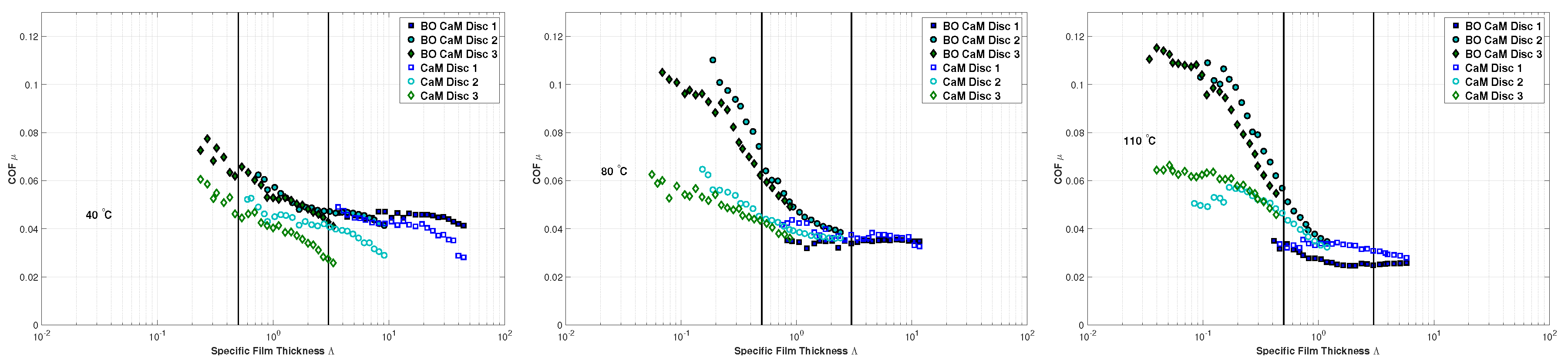
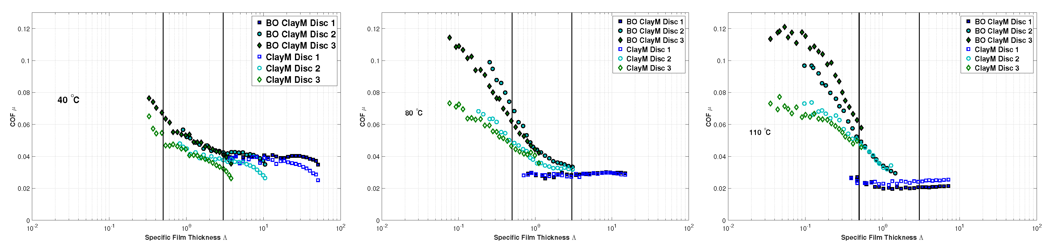
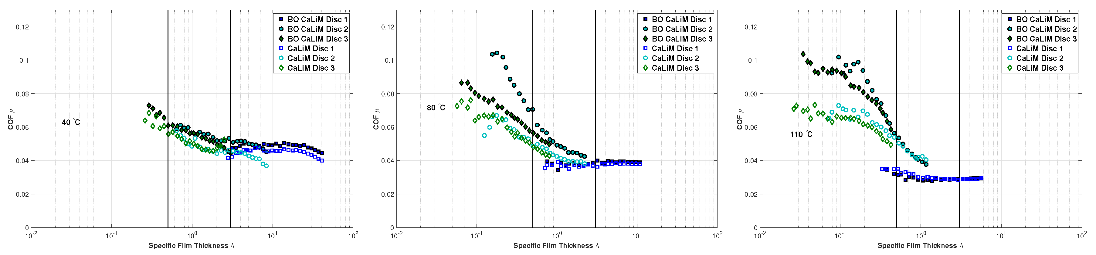
Figure 11, Figure 12, Figure 13 and Figure 14 show the coefficient of friction (COF) results plotted versus the specific film thickness () of each test at different temperatures, for each different disc (Table 2). Analysing these figures, it is clear that when the discs are changed from 1 up to 3, increasing the roughness, the tests are performed at smaller values of , and, therefore, more and more into mixed film and boundary film lubrication regimes. The same happens to a lesser extent when the temperature is increased.
Overall, the COF of greases and corresponding base oils show the typical behaviour of a Stribeck curve, where the COF is very high under boundary film, it starts to decrease as the mixed film is reached, and then reaches a minimum as it enters full film lubrication.
For certain greases, a decrease in the COF is observed at very high lambda values (left pictures of Figure 11, Figure 12 and Figure 13 which is attributed to inlet shear heating. Similar to what happens in the film thickness curves, the viscosity decreases by the temperature increase at the inlet (promoted by the high speeds) reducing the film thickness and consequently, the COF due to reduced viscous friction.
In the full film regime ( 3) but also in the mixed film zone, a decrease in the lubricants’ temperature considerably reduces the COF due to the reduction of the lubricants’ viscosity and also the churning effect. If the boundary lubrication regime is reached by increasing the temperature and reducing the viscosity, then the COF increases. As the lubrication regime approaches boundary film lubrication, the temperature effect on the COF value is reduced as the Stribeck curves tend to overlap for the same roughness.
Comparing each grease with its base oil, it seems that the COF under full film lubrication is very similar between them and perhaps slightly higher for the base oil in this region. However, as the operating conditions change (temperature, speed, roughness, or a combination of the three) and the lubrication regime enters mixed film, the COF of the base oil increases much faster and up to much higher values. In fact, the COF of the base oils is much higher than the COF of the greases for all formulations, in the boundary film zone ( 0.5). The reason behind this is surely related to the thickener and the fact that it enters the contact and increases the film thickness, reducing the COF. In fact, if the was calculated not for the film thickness of the base oils but the one of the grease, as soon as the thickener would enter the contact, the would increase again.
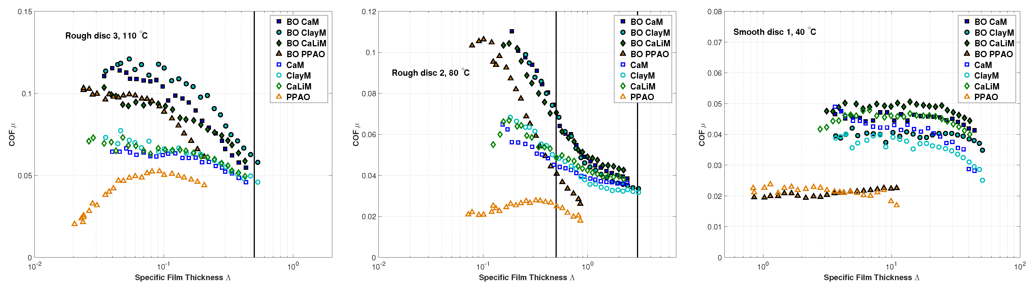
In order to compare the different lubricants, three situations were analysed as shown in Figure 15:
- Smooth disc 1 at 40 C, in full film lubrication;
- Rough disc 2 at 80 C, middle situation;
- Rough disc 3 at 110 C, in boundary lubrication.
In situation 1, the following order, from higher to smaller COF, was found:
both for the base oil and the grease, which is mainly due to a combination of base oil viscosity and base oil nature, since, in this region, the thickener type is not relevant. Greases CaLiM, CaM, ClayM are formulated with mineral oils of higher viscosity when compared to the PAO base oil of PPAO and, therefore, also show higher COF.
In situation 2, the COF order found was:
both for the base oil and the grease. In this situation, the influence of temperature and base oil nature starts to decrease as boundary lubrication is reached. The differences between greases and base oil are now much more relevant, since their COF are now very different. This behaviour is due to the thickener. The polymer grease PPAO reaches a maximum value of COF and then decreases again for lower values of showing that the thickener has a greater influence in reducing the friction for this formulation, as it did for the film thickness shown in Section 3.
In situation 3, the following order was found:
The base oils reach maximum values of COF considerably higher than the greases. In this region, the COF of the greases is much less dependent on the lubrication regime compared to the base oils. Upon reaching a maximum value, the COF of the polymer grease continues to decrease as the values of the base oil decrease.
As it happened with the film thickness, the PP thickener contribution to the COF is much more important when compared to other formulations. The COF of PPAO is always smaller both in full film and boundary film lubrication due to a combination of PAO base oil and PP thickener. The other three formulations also show considerably lower COF when compared to the corresponding base oils, as well as increased film thickness. It should be kept in mind, however, that all of the tests were performed in fully flooded conditions.
5. Conclusions
The relationship between lubrication regime and the coefficient of friction of grease lubricated contacts was addressed. It was found that the film thickness increase was promoted by thickener material entering the contact at low speeds, and it is also responsible for decreasing the coefficient of friction. This phenomenon depends on the operating conditions (entrainment speed, temperature and surface roughness) and mostly on the greases’ formulation, especially the thickener type. Therefore, in mixed and boundary film lubrication regimes, the temperature and the base oil viscosity/nature have little influence. As the lubrication regime transits from mixed to boundary lubrication, the thickener material enters the contact increasing the film thickness and decreasing the COF with respect to the base oil. At high speeds and full film lubrication, the film thickness and COF are mainly dependent on the base oil viscosity/nature, as frequently described in the literature.
It was also observed that, generally, in fully flooded conditions, the film thickness of the base oils is always smaller than the greases and the COF is equal or higher, depending on the lubrication regime.
Comparing the different grease formulations, it is clear that synthetic base oils of lower viscosity promote low friction greases, as observed before in other works related to oil and grease lubrication [9,10,21,22,31]. Of course that, a lower viscosity base oil will also generate a lower film thickness for the same operating conditions which might not be desirable. Hence, the base oil viscosity should be chosen according to the application, while in terms of base oil nature the synthetic ones should outperform the mineral ones.
Regarding the thickener type, the PP performs exceptionally well, followed by the Ca grease. The clay thickener of grease ClayM was the one producing the smaller advantage over the base oil both in terms of film thickness and coefficient of friction. Still, it should be taken into account that these results were obtained in fully flooded conditions and it would be necessary to further test these products now in starved conditions, to understand if this trend is still valid. However, it seems clear that the thickener type and content are important to determine the film thickness and coefficient of friction under low speeds, as shown in this manuscript. Furthermore, the thickener system and its interaction with the base oil are very important to control the oil bleeding rate, the additives-surface interaction and the maximum working temperature, parameters which can considerably affect the grease life and hence, the rolling bearing life. Therefore, it is clear that grease manufactures should aim to develop application-specific greases instead of multi-purpose greases.
As future work, the authors aim to extend this work to greases of different thickener and also different base oil natures. The aim would be to further study the thickener morphology and understand if and how the thickener size influences the film thickness, helping to further improve the film thickness models and prediction equations, at least in fully flooded conditions.
Acknowledgments
The authors gratefully acknowledge the funding through several projects and grants whom without this work would not have been possible:
- National Funds through Fundação para a Ciência e Tecnologia (FCT),under the PhD grant SFRH/BD/ 111868/2015 and under the projects EXCL/SEM-PRO/0103/2012 and EXCL-II/SEM-PRO/0103/2012;
- COMPETE and National Funds through Fundação para a Ciência e a Tecnologia (FCT), under the project Incentivo/EME/LA0022/2014;
- Quadro de Referência Estratégico Nacional (QREN), through Fundo Europeu de Desenvolvimento Regional (FEDER), under the project NORTE-07-0124-FEDER-000009 - Applied Mechanics and Product Development;
- NORTE-01-0145-FEDER-000022—SciTech—Science and Technology for Competitive and Sustainable Industries, co-financed by Programa Operacional Regional do Norte (NORTE2020), through Fundo Europeu de Desenvolvimento Regional (FEDER);
- Laboratório Associado de Energia, Transportes e Aeronáutica (LAETA) under the project UID/EMS/50022/2013.
The authors also wish to express their gratitude towards Axel Christiernsson International AB (Nol, Sweden) for providing the greases tested in this work.
Author Contributions
David Gonçalves conceived and designed the experiments; António Vieira and António Carneiro performed the experiments and obtained the SEM pictures; David Gonçalves, Armando V. Campos and Jorge H. O. Seabra analysed the data and wrote the paper.
Conflicts of Interest
The authors declare no conflict of interest.
References
- Åström, H.; Isaksson, O.; Höglund, E. Video recordings of an EHD point contact lubricated with grease. Tribol. Int. 1991, 24, 179–184. [Google Scholar] [CrossRef]
- Kaneta, M.; Ogata, T.; Takubo, Y.; Naka, M. Effects of a thickener structure on grease elastohydrodynamic lubrication films. Proc. Inst. Mech. Eng. J 2000, 214, 327–336. [Google Scholar] [CrossRef]
- Larsson, P.O.; Larsson, R.; Jolkin, A.; Marklund, O. Pressure fluctuations as grease soaps pass through an EHL contact. Tribol. Int. 2000, 34, 211–216. [Google Scholar] [CrossRef]
- Cann, P.M.; Williamson, B.P.; Coy, R.C.; Spikes, H.A. The behaviour of greases in elastohydrodynamic contacts. J. Phys. D 1992, 25, A124–A132. [Google Scholar] [CrossRef]
- Poon, S.Y. An Experimental Study of Grease in Elastohydrodynamic Lubrication. J. Lubr. Technol. 1972, 94, 27–34. [Google Scholar] [CrossRef]
- Kauzlarich, J.J.; Greenwood, J.A. Elastohydrodynamic Lubrication with Herschel-Bulkley Model Greases. ASLE Trans. 1972, 15, 269–277. [Google Scholar] [CrossRef]
- Cann, P.M.; Spikes, H.A. Film thickness measurements of lubricating greases under normally starved conditions. NLGI Spokesm. 1992, 56, 21–27. [Google Scholar]
- Cann, P.M. Understanding grease lubrication. Tribol. Ser. 1996, 31, 573–581. [Google Scholar] [CrossRef]
- Cousseau, T.; Graça, B.; Campos, A.; Seabra, J. Friction and wear in thrust ball bearings lubricated with biodegradable greases. Proc. Inst. Mech. Eng. J 2011, 225, 627–639. [Google Scholar] [CrossRef]
- Cousseau, T.; Björling, M.; Graça, B.; Campos, A.; Seabra, J.; Larsson, R. Film thickness in a ball-on-disc contact lubricated with greases, bleed oils and base oils. Tribol. Int. 2012, 53, 53–60. [Google Scholar] [CrossRef]
- Cousseau, T. Film Thickness and Friction in Grease Lubricated Contacts. Application to Rolling Bearing Torque Loss. Ph.D. Thesis, Departamento De Engenharia Mecanica E Gestao Industrial, Faculdade de Engenharia do Porto, Portugal, 2013. [Google Scholar]
- Couronné, I.; Vergne, P.; Mazuyer, D.; Truong-Dinh, N.; Girodin, D. Effects of Grease Composition and Structure on Film Thickness in Rolling Contact. Tribol. Trans. 2003, 46, 31–36. [Google Scholar] [CrossRef]
- Couronné, I.; Vergne, P.; Mazuyer, D.; Truong-Dinh, N.; Girodin, D. Nature and Properties of the Lubricating Phase in Grease Lubricated Contact. Tribol. Trans. 2003, 46, 37–43. [Google Scholar] [CrossRef]
- Lugt, P.M. Grease Lubrication in Rolling Bearings; WILEY: Hoboken, NJ, USA, 2013. [Google Scholar]
- Cen, H.; Lugt, P.M.; Morales-Espejel, G.E. Film Thickness of Mechanically Worked Lubricating Grease at Very Low Speeds. Tribol. Trans. 2014, 57, 1066–1071. [Google Scholar] [CrossRef]
- Cen, H.; Lugt, P.M.; Morales-Espejel, G.E. On the film thickness of grease lubricated contacts at low speeds. Tribol. Trans. 2014, 57, 668–678. [Google Scholar] [CrossRef]
- Gonçalves, D.; Graça, B.; Campos, A.; Seabra, J.H.O.; Leckner, J.; Westbroek, R. On the film thickness behaviour of polymer greases at low and high speeds. Tribol. Int. 2015, 90, 435–444. [Google Scholar] [CrossRef]
- Gonçalves, D.; Graça, B.; Campos, A.; Seabra, J. Film thickness and friction behaviour of thermally aged lubricating greases. Tribol. Int. 2016, 100, 231–241. [Google Scholar] [CrossRef]
- Fang, N.; Chang, L.; Webster, M.N.; Jackson, A. A non-averaging method of determining the rheological properties of traction fluids. Tribol. Int. 2000, 33, 751–760. [Google Scholar] [CrossRef]
- Morales-Espejel, G.E.; Wemekamp, A.W. An engineering approach on sliding friction in full-film, heavily loaded lubricated contacts. Proc. Inst. Mech. Eng. J 2004, 218, 513–527. [Google Scholar] [CrossRef]
- Brandão, J.A.; Meheux, M.; Ville, F.; Seabra, J.H.; Castro, J. Comparative overview of five gear oils in mixed and boundary film lubrication. Tribol. Int. 2012, 47, 50–61. [Google Scholar] [CrossRef]
- Fernandes, C.M.; Marques, P.M.; Martins, R.C.; Seabra, J.H.O. Film thickness and traction curves of wind turbine gear oils. Tribol. Int. 2015, 86, 1–9. [Google Scholar] [CrossRef]
- Cousseau, T.; Graça, B.; Campos, A.; Seabra, J.H.O. Grease Aging Effects on Film Formation under Fully-Flooded and Starved Lubrication. Lubricants 2015, 3, 197–221. [Google Scholar] [CrossRef]
- Yamanaka, M.; Kumagai, K.; Inoue, K.; Hata, H. Evaluation of Property Difference between Traction Oil and Traction Grease. J. Adv. Mech. Des. Syst. Manuf. 2009, 3, 366–377. [Google Scholar] [CrossRef]
- Gonçalves, D.; Pinho, S.; Graça, B.; Campos, A.V.; Seabra, J.H. Friction torque in thrust ball bearings lubricated with polymer greases of different thickener content. Tribol. Int. 2016, 96, 87–96. [Google Scholar] [CrossRef]
- Scarlett, N.A. Use of grease in rolling bearings. In Proceedings of the Institution of Mechanical Engineers, Conference Proceedings 1964–1970; SAGE Publications: London, UK, 1967; Volume 182, pp. 585–624. [Google Scholar]
- De Laurentis, N.; Kadiric, A.; Lugt, P.M.; Cann, P.M. The Influence of Bearing Grease Composition on Friction in Rolling/Sliding Concentrated Contacts. Tribol. Int. 2015, 94, 624–632. [Google Scholar] [CrossRef]
- Hamrock, B.J.; Dowson, D. Ball Bearing Lubrication; John Wiley & Sons: Hoboken, NJ, USA, 1981. [Google Scholar]
- Tallian, T.E. On Competing Failure Modes in Rolling Contact. ASLE Trans. 1967, 10, 418–439. [Google Scholar] [CrossRef]
- Spikes, H.A. Mixed lubrication—An overview. Lubr. Sci. 1997, 9, 221–253. [Google Scholar] [CrossRef]
- Brandão, J.A.; Meheux, M.; Seabra, J.H.O.; Ville, F.; Castro, M.J.D. Traction curves and rheological parameters of fully formulated gear oils. Proc. Inst. Mech. Eng. J 2011, 225, 577–593. [Google Scholar] [CrossRef]
Figure 1.
Dynamic viscosities of each base oil.
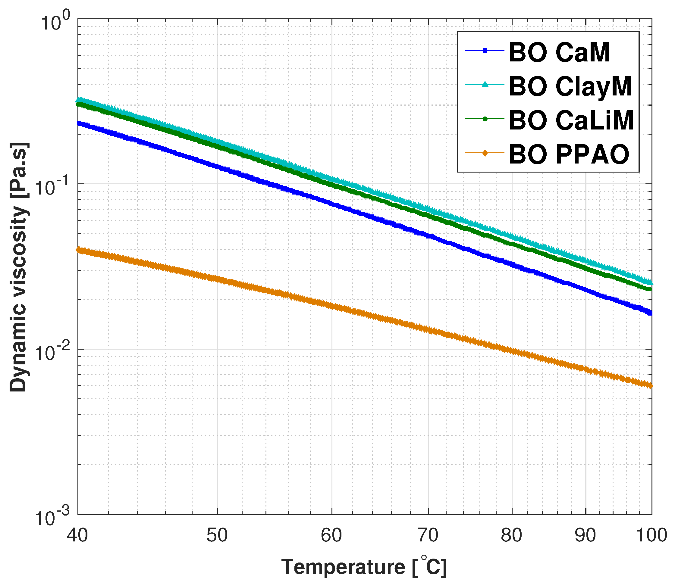
Figure 2.
SEM images of the thickener morphology of greases CaM (anhydrous calcium), ClayM (inorganic clay), CaLiM (acethic lithium azelaic stearic sarcosylic calcium) and PPAO (polypropylene).
Figure 2.
SEM images of the thickener morphology of greases CaM (anhydrous calcium), ClayM (inorganic clay), CaLiM (acethic lithium azelaic stearic sarcosylic calcium) and PPAO (polypropylene).
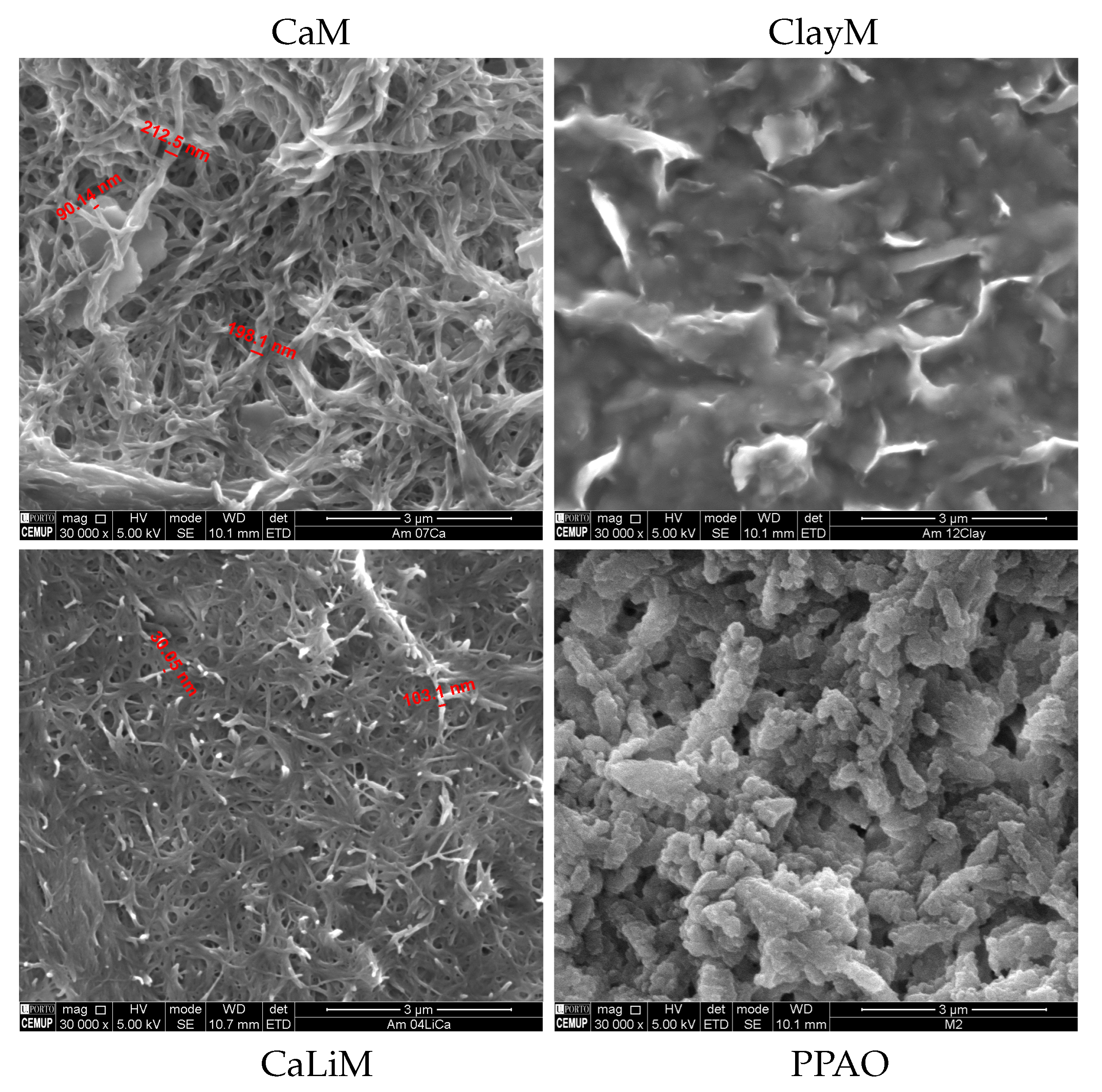
Figure 3.
Diagram of the optical interference technique used in the EHD2 equipment.
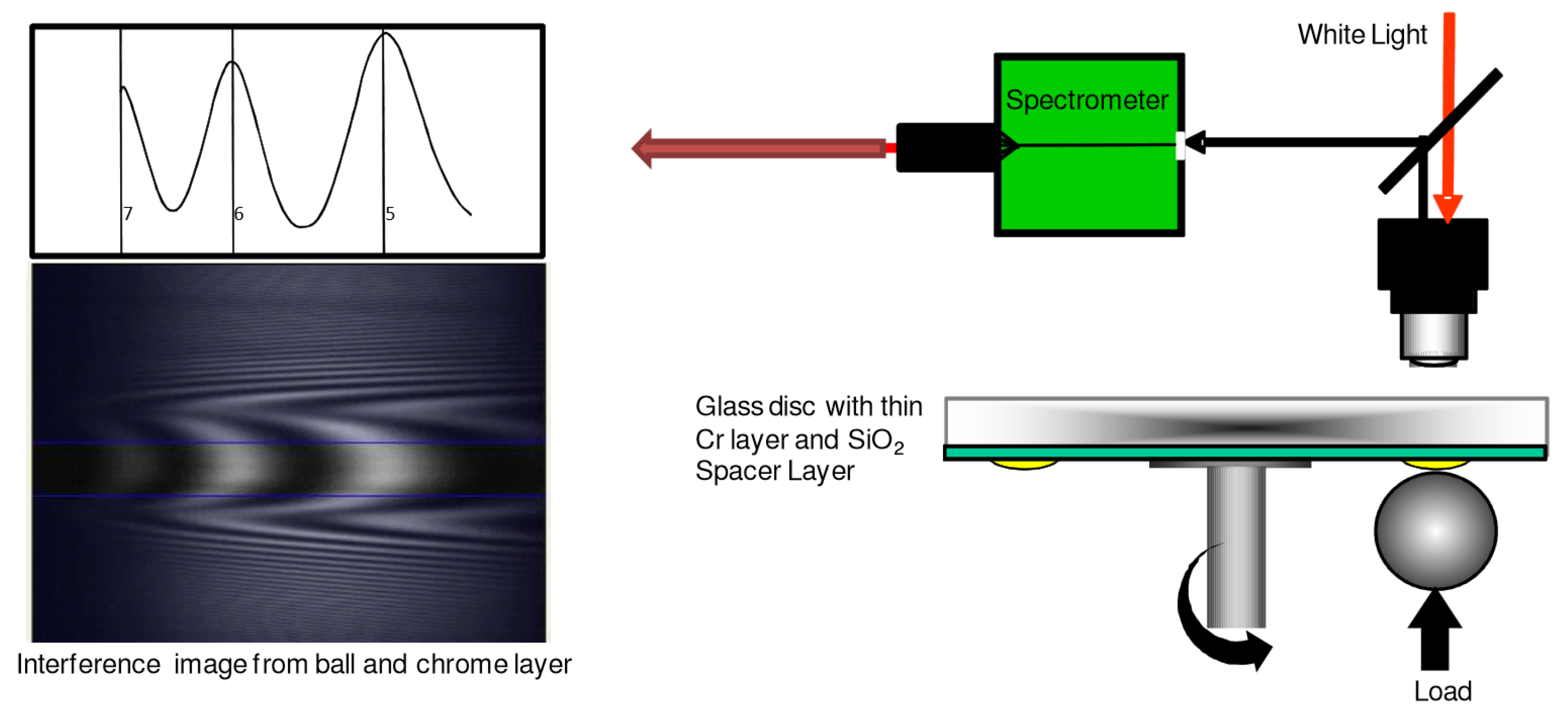
Figure 4.
Film thickness measurements of grease CaM (right figure) and the corresponding base oil (left figure) at 40, 80 and 110 C.
Figure 4.
Film thickness measurements of grease CaM (right figure) and the corresponding base oil (left figure) at 40, 80 and 110 C.

Figure 5.
Film thickness measurements of grease ClayM (right figure) and the corresponding base oil (left figure) at 40, 80 and 110 C.
Figure 5.
Film thickness measurements of grease ClayM (right figure) and the corresponding base oil (left figure) at 40, 80 and 110 C.

Figure 6.
Film thickness measurements of grease CaLiM (right figure) and the corresponding base oil (left figure) at 40, 80 and 110 C.
Figure 6.
Film thickness measurements of grease CaLiM (right figure) and the corresponding base oil (left figure) at 40, 80 and 110 C.
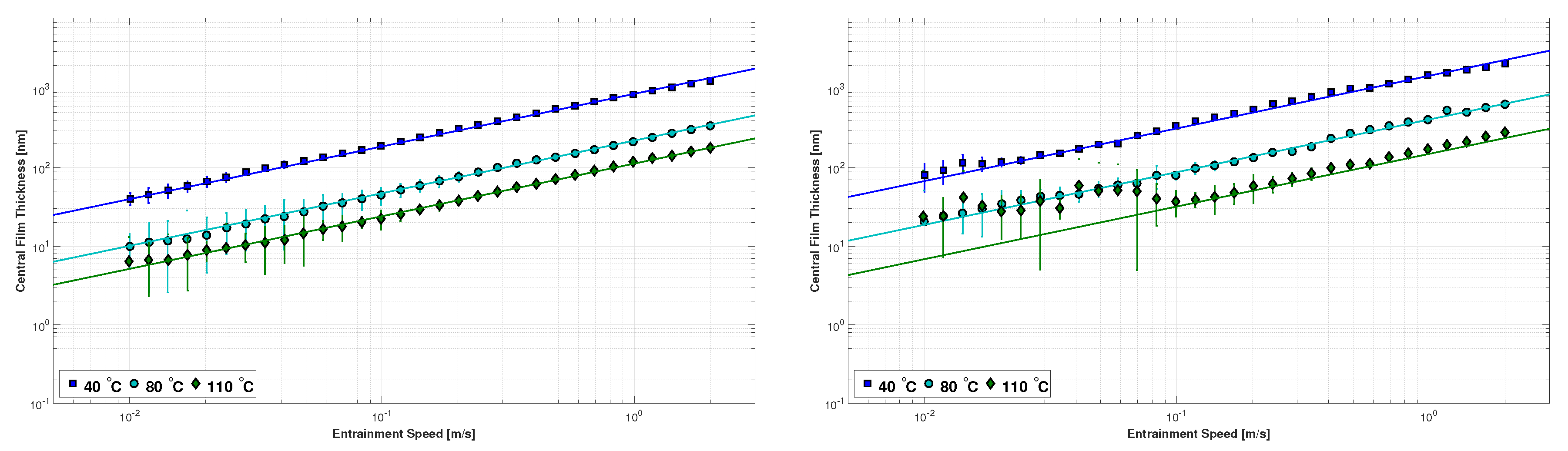
Figure 7.
Film thickness measurements of grease PPAO (right figure) and the corresponding base oil (left figure) at 40, 80 and 110 C.
Figure 7.
Film thickness measurements of grease PPAO (right figure) and the corresponding base oil (left figure) at 40, 80 and 110 C.
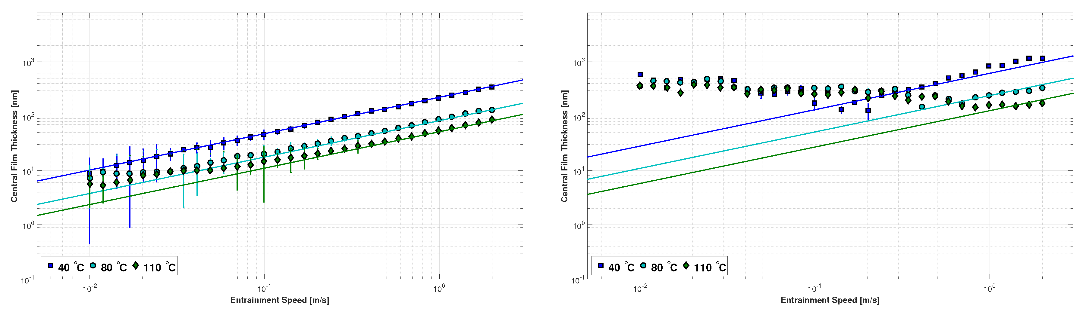
Figure 8.
Comparison between the film thickness of the different base oils (BO) at 40 and 110 C.

Figure 9.
Comparison between the film thickness of the different greases at 40 and 110 C.

Figure 10.
Typical Stribeck curve of a lubricant under constant load, temperature and slide-to-roll ratio and its correlation to the film thickness curve under the same operating conditions.
Figure 10.
Typical Stribeck curve of a lubricant under constant load, temperature and slide-to-roll ratio and its correlation to the film thickness curve under the same operating conditions.

Figure 11.
Stribeck curves of grease CaM and its base oil (BO) obtained with discs of different roughness and at 40, 80 and 110 C.
Figure 11.
Stribeck curves of grease CaM and its base oil (BO) obtained with discs of different roughness and at 40, 80 and 110 C.

Figure 12.
Stribeck curves of grease ClayM and its base oil (BO) obtained with discs of different roughness and at 40, 80 and 110 C.
Figure 12.
Stribeck curves of grease ClayM and its base oil (BO) obtained with discs of different roughness and at 40, 80 and 110 C.

Figure 13.
Stribeck curves of grease CaLiM and its base oil (BO) obtained with discs of different roughness and at 40, 80 and 110 C.
Figure 13.
Stribeck curves of grease CaLiM and its base oil (BO) obtained with discs of different roughness and at 40, 80 and 110 C.

Figure 14.
Stribeck curves of grease PPAO and its base oil (BO) obtained with discs of different roughness and at 40, 80 and 110 C.
Figure 14.
Stribeck curves of grease PPAO and its base oil (BO) obtained with discs of different roughness and at 40, 80 and 110 C.
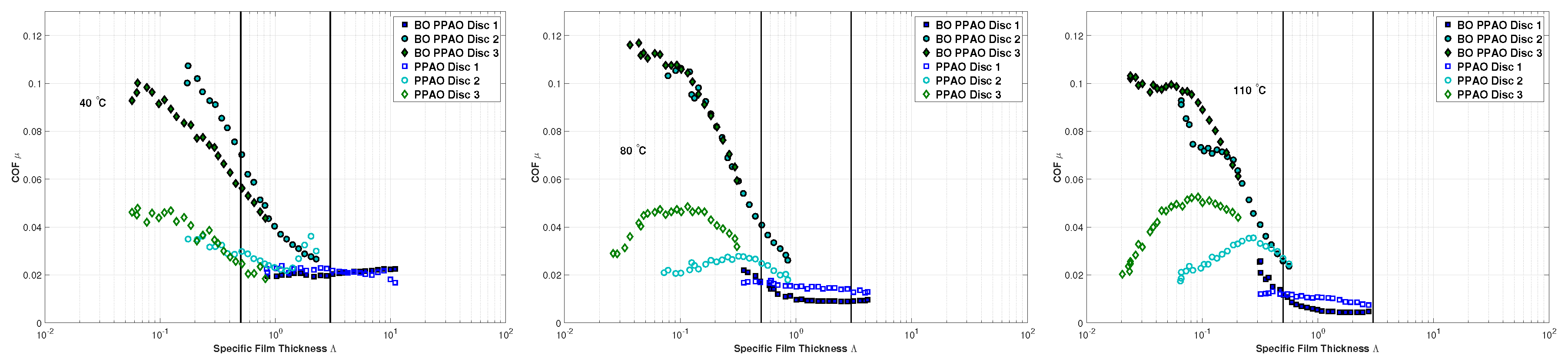
Figure 15.
Stribeck curves of greases and base oils (BO) in different operating conditions.


Table 1.
Ball-on-disc test conditions for film thickness measurements.
| Parameter | Ball | Disc |
|---|---|---|
| Radius—R (mm) | 9.525 | ∞ |
| Average roughness—Ra (nm) | ≤20 | ≈5 |
| Material | AISI 52100 | Glass |
| Elastic modulus—E (GPa) | 207 | 64 |
| Poisson coefficient— | 0.29 | 0.20 |
| Temperature—T (C) | 40, 80, 110 | |
| Entrainment speed—U (m/s) | 0.01→2 | |
| Slide-to-roll ratio—SRR (%) | 3 | |
| Load—F (N) | 50 | |
| Equivalent modulus—E* (GPa) | ≈51.8 | |
| Max. Hertzian pressure—p (GPa) | ≈0.66 | |
| Hertzian half-width—a (m) | ≈190.7 | |
Table 2.
Ball-on-disc tests: surface roughness of the surfaces used for Stribeck curves measurements.
Table 2.
Ball-on-disc tests: surface roughness of the surfaces used for Stribeck curves measurements.
| Parameter | Ball | Disc 1 | Disc 2 | Disc 3 |
|---|---|---|---|---|
| R (mm) | 9.525 | — | ||
| Ra (m) | 0.022 | 0.008 | 0.143 | 0.397 |
| Rq (m) | 0.034 | 0.010 | 0.203 | 0.579 |
| Rz (m) | 0.170 | 0.050 | 1.447 | 3.608 |
| Rmax (m) | 0.310 | 0.061 | 1.937 | 5.768 |
Average values of three different radial zones.
Table 3.
Ball-on-disc test conditions for measuring the Stribeck curves.
| Parameter | Ball | Disc |
|---|---|---|
| Radius—R (mm) | 9.525 | ∞ |
| Material | AISI 52100 | AISI 52100 |
| Elastic modulus—E (GPa) | 207 | 207 |
| Poisson coefficient— | 0.29 | 0.29 |
| Temperature—T (C) | 40, 80, 110 | |
| Entrainment speed—U (m/s) | 0.04 → 2 | |
| Slide-to-roll ratio—SRR (%) | 5 | |
| Load—F (N) | 50 | |
| Equivalent modulus—E* (GPa) | ≈113 | |
| Max. Hertzian pressure—p (GPa) | ≈1.09 | |
| Hertzian half-width—a (m) | ≈146.8 | |
Table 4.
Ratio between the film thickness of the grease and that of the base oil in the high speed region.
Table 4.
Ratio between the film thickness of the grease and that of the base oil in the high speed region.
| Grease Ref. | CaM | ClayM | CaLiM | PPAO |
|---|---|---|---|---|
| 2.3 | 1.7 | 1.7 | 2.8 |
© 2017 by the authors. Licensee MDPI, Basel, Switzerland. This article is an open access article distributed under the terms and conditions of the Creative Commons Attribution (CC BY) license (http://creativecommons.org/licenses/by/4.0/).
Share and Cite
MDPI and ACS Style
Gonçalves, D.; Vieira, A.; Carneiro, A.; Campos, A.V.; Seabra, J.H.O. Film Thickness and Friction Relationship in Grease Lubricated Rough Contacts. Lubricants 2017, 5, 34. https://doi.org/10.3390/lubricants5030034
AMA Style
Gonçalves D, Vieira A, Carneiro A, Campos AV, Seabra JHO. Film Thickness and Friction Relationship in Grease Lubricated Rough Contacts. Lubricants. 2017; 5(3):34. https://doi.org/10.3390/lubricants5030034
Chicago/Turabian StyleGonçalves, David, António Vieira, António Carneiro, Armando V. Campos, and Jorge H. O. Seabra. 2017. "Film Thickness and Friction Relationship in Grease Lubricated Rough Contacts" Lubricants 5, no. 3: 34. https://doi.org/10.3390/lubricants5030034
Note that from the first issue of 2016, this journal uses article numbers instead of page numbers. See further details here.