Damage Equivalent Test Methodologies as Design Elements for Journal Bearing Systems


Chair of Mechanical Engineering, Montanuniversität Leoben, 8700 Leoben, Austria
*
Author to whom correspondence should be addressed.
Lubricants 2017, 5(4), 47; https://doi.org/10.3390/lubricants5040047
Submission received: 31 October 2017
/
Revised: 29 November 2017
/
Accepted: 8 December 2017
/
Published: 14 December 2017
(This article belongs to the Special Issue Friction and Lubrication of Sliding Bearings)
Abstract
:The current paper addresses the field of experimental research of journal bearing systems. In this regard, the challenges are dealt with concerning simultaneous testing with a close correlation to the industrial application and with a high resolution of tribological processes. Concerning this aspect, two damage equivalent laboratory test methodologies for journal slide bearing systems are presented, and their ability to visualize certain performance parameters of bearing systems are emphasized (for instance friction performance, (start stop) wear processes, and seizure events). The results clearly emphasize that the applied methodologies provide accurate findings regarding specific effects of selective parameters/changes on the performance of bearing systems, such as polymer overlays may result in improved mixed friction sliding conditions if designed properly, and they provide superior start stop wear resistance; the use of specific corrosion inhibitors can successfully prevent tribo-corrosion on bronze bearings; a decrease of oil viscosity increases solid friction share but decreases fluid friction; lubricant anti-wear additives are able to improve seizure resistance and sliding properties of bearing systems depending on formulation harmonization; and novel bearing material coatings, e.g., sputtered SnCu, can significantly improve emergency running capabilities.
1. Introduction
In various applications of technical systems, there is a need to hold, guide, and support linear moving or rotating parts by means of slide bearing components. In particular, slide bearings, also referred to as journal bearings or plain bearings, are used in different types of internal combustion engines under various operating conditions [1,2]. Hence, journal bearings are used in manifold application areas, which are, time and again, additionally subjected to profound and rapid changes to affect an improvement in the performance; e.g., re-design of combustion engines to limit exhaust gas emissions. As a result, on the one hand, product development times of bearing systems including bearing material, shaft material, and the lubricant in between need to be short, whereas, on the other hand, simultaneously a large scope of solutions need to be provided.
Basically, decisive performance parameters of journal slide bearing systems are related to their reliability and efficiency for all lubrication conditions [2,3]. Reliability of journal bearings for a sufficient life time covers several mechanical and tribological requirements depending on the lubrication regimes of the journal bearings. With regard to tribological demands, especially tribological system robustness (e.g., high resistance against seizure events, wear resistance during start-stop and resistivity against disturbance variables such as dirt particles) represents a main criterion. The efficiency of a journal bearing is rated by means of the resulting frictional losses, viz. the coefficient of friction (COF, µ).
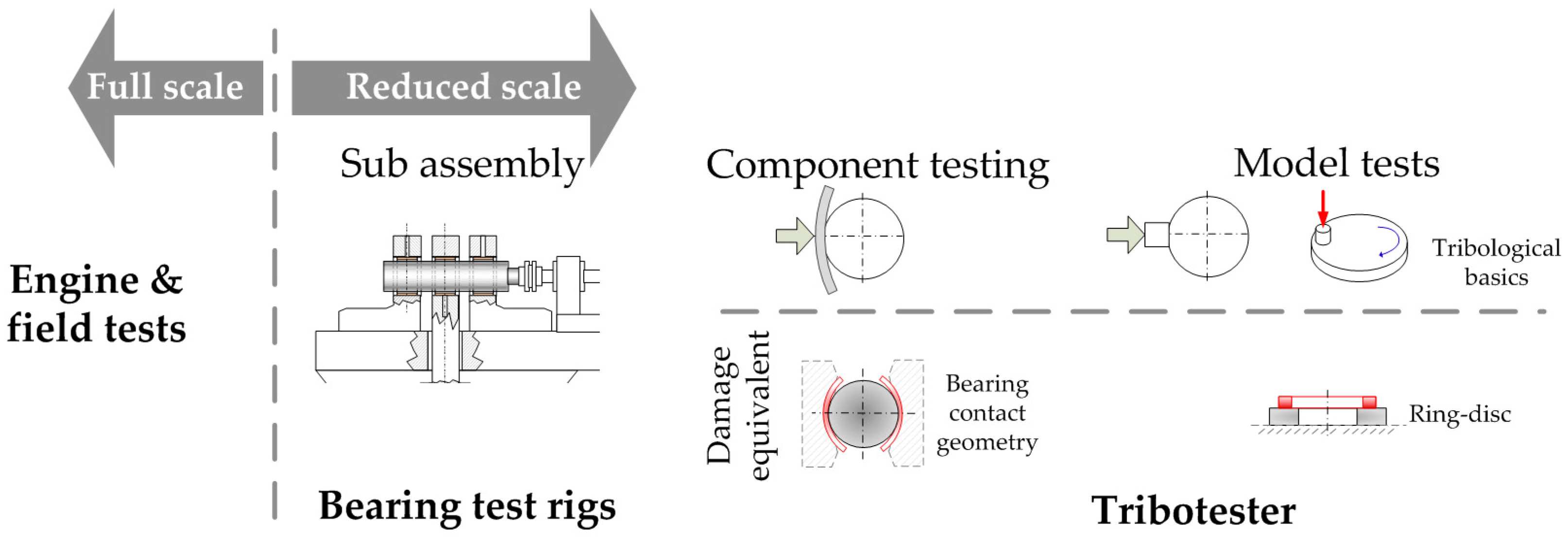
The development and design process of slide bearing systems according to the previously described demand is conventionally based on either testing or simulation, or rather a combination thereof. The latter has not yet progressed so far in order to fully elucidate the complex processes during boundary and mixed friction sliding. In this regard, material design of bearing materials, shaft materials, and lubricants and studies on tribological phenomena still rely on experiments. Basically, experimental investigations of tribological systems can be carried out according to various test categories described in [4]. The classification of journal bearing test categories can be defined accordingly by splitting investigations into those with full scale systems and those testing reduced systems. A visual depiction of the following explanatory notes is seen in Figure 1.
Full scale tests provide a final performance evaluation of the whole system including the performance during application. For instance, in [5], field examinations of high speed diesel engines are presented. The results of these activities highlight the main tribological bearing damages occurring in the field. The damages are based on several categories of wear (adhesive, abrasive, corrosive, etc.) based on root causes; e.g., oil film breakdown due to overload, vibrations or insufficient oil supply in case of adhesive wear or seizure events; or oil contamination with foreign particles or wear debris considering abrasive wear. However, full scale tests are often incapable of elucidating individual processes occurring in the tribological contact itself nor the corresponding friction losses. In this regard, investigations of selective parameters or directed optimization processes are hardly possible. This limits usability of full scale tests for screening applications and in-depth studies of single effects. Furthermore, reality proves that every application is somehow different. Therefore, full scale tests are inefficient in terms of costs and time. This conflicts with shortened product cycles and rapid changes of the application requirements. Considering this, laboratory test systems on a reduced scale provide valuable advantages towards efficient investigations of bearing systems.
In literature, several concepts of subscale systems for journal bearing systems can be found. Bearing test rigs, representing subassembly systems loaded by hydropulsating or electromechanical actuators, are widely used in combination with customized test procedures [1,6,7]. These test stands are successfully used in predicting hydrodynamic load bearing capabilities and wear-fatigue phenomena [8]. However, several studies point out the limited measurement and control accuracy of these rigs for certain investigation topics owing to complex rig assemblies [9,10].
Hence, besides bearing test rigs, reduced systems on tribotesters, also referred to as tribometer test rigs, have emerged aiming for high visualization power of tribo-processes and manifold measurement parameters. In this regard, tribological model scale set ups including micro abrasion testers [10], scratch tests [11], or pin-on-disc systems [12] are compromisingly carried out to gain a better understanding about the basic tribological phenomena of sliding surfaces. However, it is also emphasized in literature that various basic model test configurations, such as pin-on-plate, fail to reproduce damage mechanisms and tribological functionality of journal bearing applications, such as shown in [13]. Hence, damage equivalency is regarded as a mandatory aspect when using a model test configuration for bearing research in order to transfer results from model tests onto journal bearing application environments [14]. More seldom, tribological test configurations for bearing systems are reported in literature, which can be referred to as being closer to the component. They characteristically use parts of bearing half shells in a block-on-ring testing configuration and are employed for bearing material characterization [15,16]. Their advantage is the ability to perform tests independent of a journal bearing manufacturer, as bearing half shells from series production can be used. However, these test set-ups provide a limited transferability of the results obtained on a model level as being more of a line contact due to large differences in the curvature of the block and ring. To achieve transferability from subscale tests to real life bearing systems, similar contact conditions are needed in the first place followed by motion equality.
The current paper presents successfully established damage equivalent test set ups under laboratory conditions using ring-on-disc (RoD) model test configuration and a bearing segment (BS) system. In particular, the abilities of the herein proposed test methodologies for characterization of friction efficiency and tribological damage mechanisms of bearing systems are demonstrated with the aid of a comprehensive compilation of representative tribometric results for each system.
2. Test Methodologies Employed
2.1. Approach
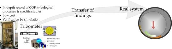
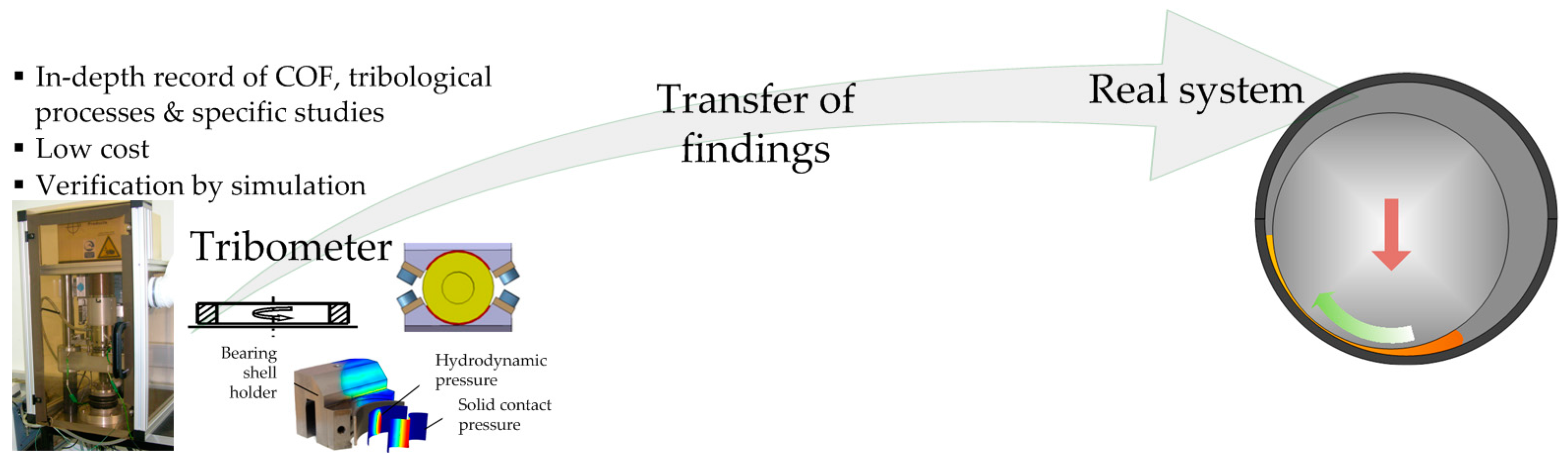
The use of the presented test methodologies implemented on tribometer test rigs follows the approach given in Figure 2. A valuable experimental test for tribological purposes needs to trigger similar contact processes to the real application. Furthermore, testing has to consider the whole system performance which derives from the interactions of the topographical and chemical characteristics of the surfaces, the physical and chemical properties of the lubricant, and the overall conditions under which sliding takes place, for e.g., speed, load, temperature, environmental conditions, or contact situation. Concerning bearing systems, it is of utmost importance to test on a reduced scale to provide sliding and damage equivalency to engine bearings. Therefore, application related testing on a reduced scale is a mandatory aspect for optimization of journal slide bearings [6]. The herein proposed test methodologies combine high visualization power of tribological processes under laboratory conditions, high efficiency, and excellent cost effectiveness as well as tribological equivalency of contact situations and damage processes to real life journal bearing systems. Hence, these test configurations are referred to as damage equivalent. Cost and time efficient tests are carried out with the laboratory test configuration accompanied with precise measurement of the tribological performance. This provides comprehensive and in-depth studies of bearing systems. Subsequently, knowledge obtained with these test rigs can be transferred to application, keeping in mind the restrictions by reducing the degree of realism.
2.2. Damage Equivalent Model Test Method—Ring-on-Disc
A schematic depiction of the applied set up and the area of testing are shown in Figure 3a. In a ring-on-disc (RoD) test configuration, contact between a moving disc/ring and a fixed disc/ring counterpart in an axial direction takes place. The herein presented set up uses plain contact partners immersed in oil for bearing investigations and, therefore, is able to mimic contact situations and damage processes of real scale bearing systems in boundary and mixed friction. Hence, seizure events especially or wear processes as well as mixed friction performance of bearing systems can be addressed with this set up. The disc specimens, which are made of the bearing material, are realized with four notches splitting the area of contact. This results in easy oil entrainment into the contact. The test set up differentiates from many other model set ups in terms of reproduction of contact situations of real scale bearings owing to the following considerations:
- Large area contact situation and prevention of line contact situations potentially occurring due to misalignment and bearing of the load through the edges.
- Ensured oil entrainment into the contact realized by oil notches.
- Rotary sliding condition.
For instance, the difference to the pin-on-plate set up has been emphasized in [13], for e.g., the difference in lubrication type, area of contact or depiction of friction, and temperature characteristics. The ring-on-disc configuration is implemented within a tribometer test rig from Phoenix Tribology Ltd. (Kingsclere, UK). Tribological properties and phenomena can be tested and recorded comprehensively due to a broad range of set values (loading, speed, and heating) and measured values. Owing to a low level of friction power, the tribo-processes and failure mechanisms are decelerated and can be studied in detail. Figure 3b shows a photo of the TE92 test rig with the ring-on-disc configuration mounted as well as several measurement sensors applied. Additionally, a computer-aided design (CAD) drawing of the RoD test cell is depicted, giving a closer look into the set up assembly. The loading of the test cell is realized with the aid of an air bellow. Two thermocouples facilitate the measuring of the temperature level of the ring specimen (4.5 mm below the contacting surface) as well as a contact near temperature (1 mm below the contacting surface) within the shaft specimen closely below the area of contact. The temperature level is settled by using the ring specimen temperature, whereas the system can be heated by two heating elements beneath the oil bath. The coefficient of friction is deduced by a load cell (considering the distance ratio of the load cell and the contact from the axis of symmetry), which is mounted on the left of the test cell and comes in contact with the pivot mounted oil bath under loaded conditions. The motor and the test cell are isolated from each other, which enables the measurement of the electrical resistance, also referred to as contact potential (CP), of the contact between ring and disc according to the method of [17]. Additionally, qualitative depiction of wear processes is possible by using a capacitive displacement sensor responding the relative wear height between ring and disc. Furthermore, an acoustic emission technique using a Piezotron Sensor Type 8152B from Kistler (Winterthur, Switzerland) with a sampling frequency of 850 kHz has been successfully integrated [18]. The range of set parameters and measured quantities, which can be recorded with a frequency up to 10 Hz, are listed below:
- Set values: normal load (0–10 kN), sliding speed (0–3000 rpm), temperature level (20–200 °C)
- Measured values: friction torque (0–15 Nm), contact temperature (0–250 °C), specimen temperature (0–250 °C), contact resistance (0–51 mV), wear height (0–500 µm), acoustic emission (50 kHz–400 kHz)
Furthermore, a modified ring-on-disc set up using thrust washer counterparts has already been successfully designed. The narrowing gap in the case of thrust bearing specimens facilitates a hydrodynamic effect and enables test conditions closer to a bearing operation. Details as well as selective results of the thrust washer ring-on-disc set up are presented in [19]. Considering cost aspects of the specimen, manufacturing the system with plain surfaces is done more frequently and represents a sort of a standard version.
2.3. Component Close Test Method—Bearing Segment System
This novel test configuration enables component testing of journal bearing systems in combination with precise depictions of the friction characteristics. In this set up, a two-sided lubricated contact between two real life bearing shells, which are reduced to 120°, and a rotating shaft specimen takes place, see Figure 4a. Geometric equivalency to full scale parts facilitates studies concerning friction performance for all lubrication regimes and damage processes, such as start stop wear or seizure events, close to component conditions. The currently used shaft diameter is ~48.6 mm. The curvatures of the shaft and bearing are adjusted to equal 1.6 per mill clearance in 360° journal bearings. Figure 4b shows a corresponding photograph of the test rig with implemented bearing segment test configuration in a loaded condition as well as a CAD drawing of the test set up including shaft and bearing shell specimen holders. The depiction shows several sensors applied, measuring the ongoing sliding and tribological processes during testing in detail. This includes two thermocouples, one installed at the back of a bearing shell and one placed on the bottom of the oil bath, which is used for heating control of the set up by four heating rods. Analogously to the RoD set up, friction is deduced by torque measurement through the load cell located on the left side of the test cell (considering the distances from the load cell to the symmetrical axis of the contact) contacting with the pivot mounted oil bath assembly. This measurement principle enables precise detection of the friction resistances of the contacts between bearing shells and shaft and does not record any dead loads or dragging forces from any supporting structure. Normal load is applied by means of an air bellow and transmitted to the contact by two lever arms. Also for this set up, an electrical contact resistance measurement method exists along with acoustic emission recording possibilities. Furthermore, a lubricant pressure sensor can be implemented through a drilled hole in one of the bearing shell specimen holders (high loaded region) giving additional insight into the contact situation by visualization of the transition between boundary and mixed friction regime. The range of set and measured values are given below:
- Set values: normal load (0–10 kN), sliding speed (0–6000 rpm), temperature level (20–200 °C)
- Measured values: friction torque (0–15 Nm), bearing back temperature (0–250 °C), oil bath temperature (0–250 °C), contact potential (0–51 mV), lubricant pressure (up to 300 bar), acoustic emission (50 kHz–400 kHz)
Standard data acquisition can be carried out up to 10 Hz for all previously listed parameters. In addition, the COF, the sliding speed, the normal loading, and the CP signal can be measured precisely by data acquisition up to 10 kHz. This can be used for instance to visualize quick events, such as start and stop events of an engine.
3. Results
3.1. Visualization of Friction
Figure 5 highlights the visualization possibilities of the presented test methodologies regarding friction performance of journal bearing systems, whereby Figure 5a,b depict results obtained with the bearing segment system and Figure 5c,d show results obtained with a RoD set up. As shown in Figure 5a, the bearing segment test set up precisely visualizes differences of the friction performance induced by variation of the bearing material. The test data shown have been recorded during start stop testing (cycle number 1800) with a constant load of 1.64 N/mm2, 100 °C oil bath temperature, and a 5 s speed ramp. Basically, for both bearing materials, the states of lubrication regimes are exemplified. The plateaus of µ highlight the boundary friction regime. The decrease of µ indicates mixed lubrication regimes with significant hydrodynamic friction share. The reach of a minimum value and a re-increase of the friction coefficient describe the transition to the full fluid friction condition. This is also emphasized by the CP signal, which moves up, thus indicating the separation of the metallic surfaces previously in contact. The use of different materials affects, particularly, boundary and mixed friction sliding conditions. Material A represents a softer bimetal bearing (lining material and steel back) known for good emergency running capabilities. Material B is an optimized tri-layer, also referred to as trimetal, bearing product (steel back, lining material, and overlay) with a polymer coating. It is seen that Material B provides lower friction in a boundary sliding regime compared to that of Material A, but, overall, the Stribeck curve generated with Material B is more expanded to the right side. The noted effects can be plausibly linked with the material properties. Material B shows low solid friction properties, but has a higher surface roughness, which requires running in to shift the Stribeck curve to the left. Hence, the obtained data precisely describes the tribological phenomena within the contacts taking place. Figure 5b highlights the impact using various lubricant viscosities on friction characteristics. As seen, the boundary sliding regime with the plateau of µ is not affected. With the increase of sliding speed and transition to mixed friction, the impact is seen. With lower oil viscosity, boundary friction as well as the mixed friction regime are expanded towards higher speed. During fluid friction, higher lubricant viscosity implies higher friction losses.
The test set ups are also capable of visualizing systematical effects on the friction performance deriving from material optimization. In this regard, Figure 5c shows the differences of a common AlSn20+ bimetal bearing and an advanced AlSn25+ bearing alloy with an enhanced microstructure obtained with RoD set up. It is clearly visible that the alloy with higher tin content and improved structure shows a better friction performance at low speed when the solid friction share prevails.
Furthermore, the effect of additive tribofilms, owing to interactions of the mating surfaces with the engine oil additive system, on the friction performance under mixed friction sliding conditions can be determined, see Figure 5d. In this test procedure, load (3 MPa) and speed (1.4 m/s) are kept constant while the heating level has been set as depicted. Oil 1 represents a fully formulated heavy duty diesel engine oil, whereas in the case of Oil 2, a surface active additive compound is missing with the rest of the formulation being equal. It can be noted that the system with tribofilms forming based on the use of Oil 2 provides significantly lower friction losses. Hence, this visualizes the possibility to investigate particular changes of the oil additive system on friction performance of bearing systems.
3.2. Assessment of Tribological Damage Mechanisms
Friction and wear processes are directly connected with each other within tribological systems. The following section deals with the elucidation of damage processes occurring in journal bearing systems by using the test methodologies herein proposed.
3.2.1. Evaluation of Wear Processes
Generally, both systems are superbly capable of evaluating wear processes going on in journal bearing systems. Figure 6a,b show the material effect regarding wear resistance and failure tolerance during mixed friction sliding. The test data have been determined with the RoD set up in a temperature test procedure (load and speed are constant as shown). In Figure 6a a system using a lead free bronze lining is depicted. The plot shows a running in process at room temperature (RT) and during the initial heating step indicated by the drop of µ. At elevated temperatures of 100 °C, stable sliding conditions with low µ, high CP, which indicates the formation of boundary layers and protective interface processes and no wear evolution during this period, takes place (the reader may note that during the heating period the wear graph is influenced by the temperature changes). However, during the heating step to 140 °C, the vulnerable system behavior is emphasized. Shortly after starting the second heating period, the minor changes of temperature result in the start of wear processes. The CP signal drops at first, followed by a minor increase of µ as well as a slight raise in the wear graph. When the CP reaches its minimum, severe wear processes start, indicated by high wear rates, high µ, and an increase of friction heat. In contrast, the similar system using a lead free bronze lining but coated with a polymer overlay is shown in Figure 6b. During the whole test procedure, no significant wear events take place. This is documented by the various measured parameters and verified by gravimetric wear measurement. The relative wear height is influenced by the heating situation, which changes the capacitive signal. Therefore, a wear graph, which only follows the temperature level, indicates that no significant wear processes take place. Furthermore, it can be seen that no significant friction heat is recorded, the CP signal is high during the whole test, and µ is constant and low after running in. A further example of the visualization capability of sliding and wear processes of the RoD set up is documented by the authors in [20], focusing on the functionality of AlSi sliding material.
Furthermore, wear processes induced by start stop motion can be replicated by the herein presented test configurations. In Figure 6c, the wear evolution during start stop conditions (1.64 MPa, 120 °C oil bath temperature, 0–1.25 m/s in 5 s) obtained with the bearing segment set up is given. In this regard, two different materials are shown. In the case of the lead trimetal bearing, a pronounced wear evolution after short number of cycles (below 20,000) settles. In contrast, it can be highlighted that using an advanced polymer coating instead of the lead coating improves the start stop wear resistance crucially. The differences emphasized by the test data are confirmed by surface analysis shown in Figure 6c. In this depiction, the conditions of two bearing shells with lead and polymer coating are compared with each other after a similar number of start stop cycles. The wear track of the lead coating is clearly visible, whereas the polymer coating appears close to new conditions. Also elsewhere, the superiority of polymer overlays concerning start stop wear resistance is documented [21], which proves the validity of the results herein presented. A detailed study by the authors concerning start stop wear of bearing systems using the herein applied bearing segment system is published in [22].
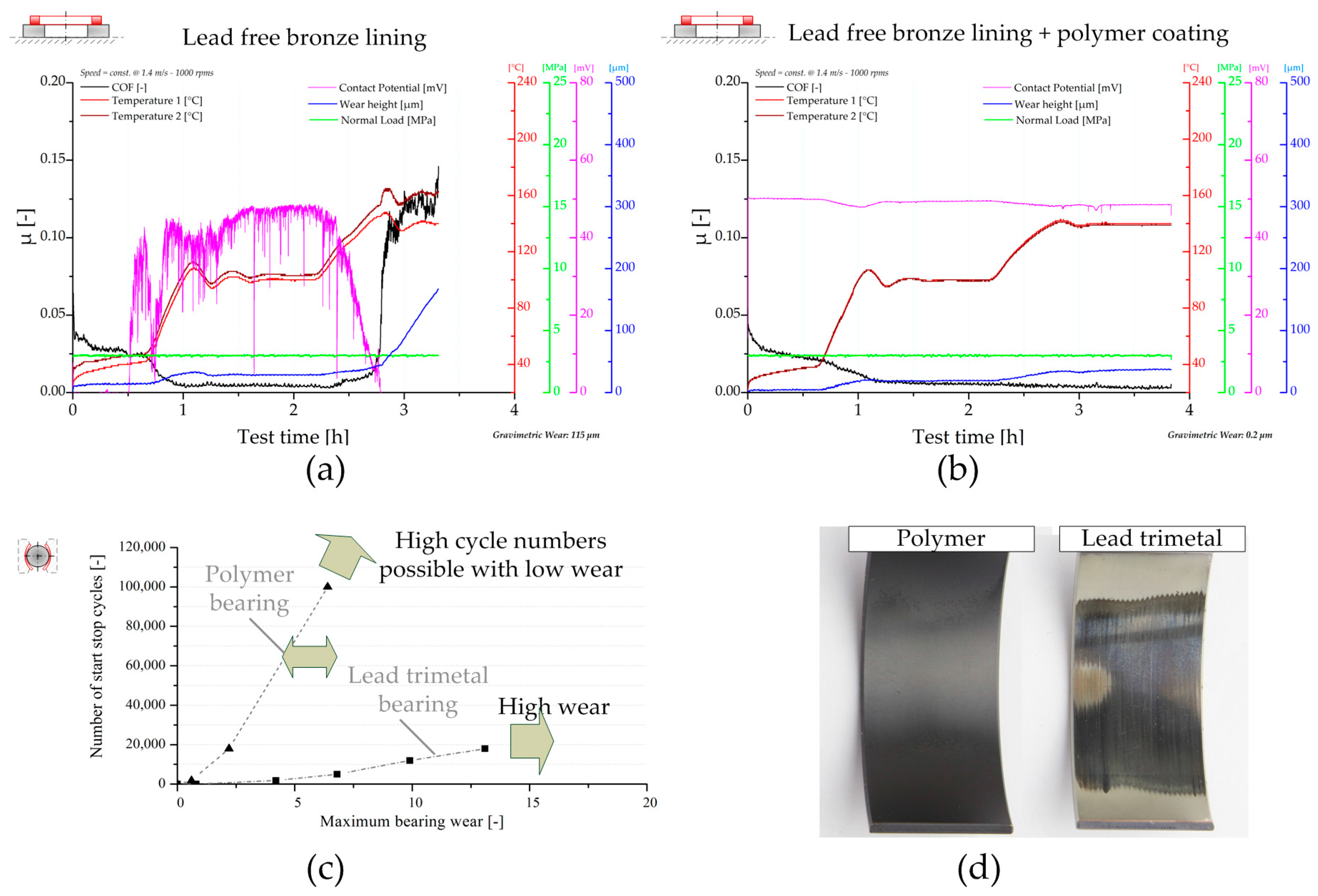
Furthermore, the tribo-chemical wear processes can be resolved. Figure 7 depicts the effect of corrosive wear on lead free bronze bearing material as well as the prevention thereof by using specific corrosion inhibitors (CIs). In the case of Oil C, a corrosion layer containing S and Zn forms on the bronze material, see Figure 7a. This effect is also visible by the naked eye as emphasized in Figure 7b. These processes affect sliding and wear conditions, highlighted in Figure 7c showing a temperature step test procedure with constant speed at 1.4 m/s and 3 MPa loading. The friction curve of the system using Oil C rises at elevated temperature, thus indicating adhesive processes. In contrast, optimized lubricant design with corrosion inhibiting components (Oil D) results in prevention of this layer formation, see Figure 7b. The resulting wear performance indicates a stable sliding condition paired with low friction losses.
The conclusions and knowledge acquired with testing find their application in the improvement and development of products as well as in the numerical life time analysis and product design. The cornerstone of numerical wear assessment was laid by Archard and Hirst [23]. The authors proposed the model according to Equation (1), which correlates properties of the mating surfaces of journal bearing and shaft with the external load P:
In this equation, W is the worn volume, s the sliding distance, pm the flow pressure of the softer material, and K a material-related empirical constant describing the probability of the formation of a wear particle. The transformation of Equation (1) into an ordinary differential equation, see Equation (2), provides the mathematical base for the numerical wear evaluation, where w is the wear height, p the asperity contact pressure, v the sliding speed, and C is an empirically determined parameter that describes the relation between wear volume and the introduced frictional energy during sliding solid contact [24]. The steps behind this transformation include the division of Equation (1) by the nominal contact area and the derivative with respect to time. Consequently, the normal load P transforms to a pressure which is correlated to the asperity contact pressure to evaluate solely the effects resulting from asperity interactions. The time derivative transforms s into v while C unites the material intrinsic parameters K/pm.
In recent years, numerical tools have been developed at the Chair of Mechanical Engineering which allow the investigations of conforming and non-conforming contacts in regard to friction and wear phenomena. The tribological simulations of (thermo-)elastohydrodynamic contacts, for e.g., gear tooth contact and journal bearing, are conducted with COMSOL Multiphysics. By considering Equation (2), wear and its effect on the lubrication gap’s geometry can be modelled fully, coupled with the equations describing the physics of (T)EHL. For presentation purposes, a numerical scenario derived from conducted tests on the BS was chosen. The model of the core parts of BS is depicted in Figure 8. In accordance with the real test setting, the force is applied on boundary A while the Reynolds equation, the equation representing asperity contact pressure according to Greenwood and Williamson [25], as well as Equation (2) are solved on boundary B, allowing for the resolution of friction and wear processes. The contact behavior represented by an analytical function calculated based on the theory by Greenwood and Williamson is considered unaffected by roughness changes due to wear for the entire numerical scenario. The effect of wear is considered in the change of the lubrication gap’s geometry. In interplay with the initial lubrication gap height h0 and the structural deformation u, the wear height determines the lubrication gap’s height. C, D, and E represent the boundaries to the surrounding structure. The guiding function of the surrounding structure is considered by the application of roller conditions, which restrict deformation in the boundary’s normal direction.
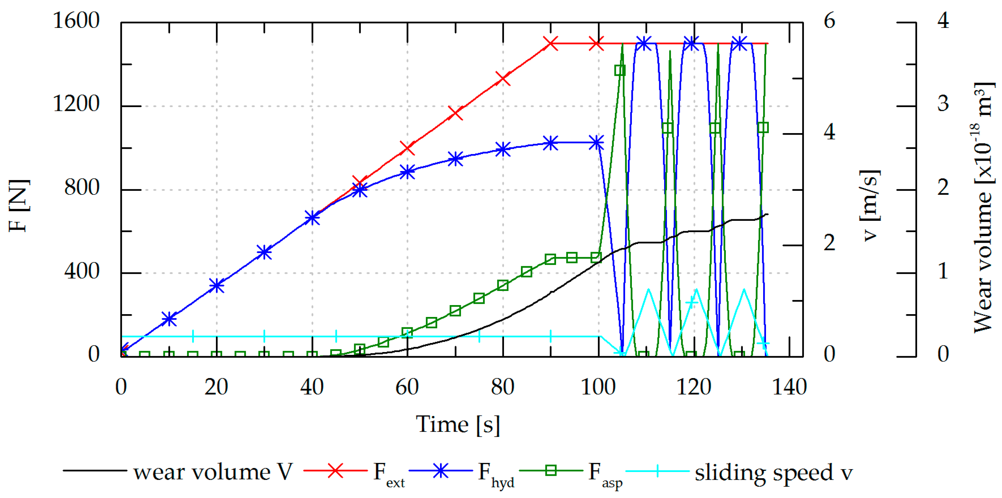
A representative numerical scenario based on conducted tests is depicted in Figure 9. A value of 1.4 × 10⁻¹³ [m3/Nm] is chosen for C. The thermal conditions are considered to be constant. For the quantitative comparison with conducted tribological tests, the numerical frameworks allows for the implementation of temperature dependent oil parameters. In the initial state, the system operates in the fluid lubrication regime under a low external load of Fext = 1500 N, a unit load of 1.65 MPa, and a sliding speed v of 0.37 m/s, which is kept constant until t = 100 s. Fext is totally carried by the force resulting from the hydrodynamic pressure Fhyd. By increasing Fext the system is steadily pushed towards harsher loading conditions. The system counteracts the increasing load by decreasing the fluid film thickness, which results in an increased hydrodynamic load carrying capacity. However, when the fluid film thickness drops within the range of surface roughness, asperities start to interact, resulting in a rising Fasp. At 40 s, the system turns into the mixed lubrication regime indicated by the onset of the asperity contact force Fasp. Simultaneously, the wear volume starts to rise and depicts an exponential run until the time of 100 s at which start stop cycles begin. During the times of low speeds, the hydrodynamic load carrying capacity is insufficient. Consequently, Fasp contributes to help carry the external load. Within this period of time, wear due to solid contact occurs and a rise of the wear volume can be observed. During the phases of sufficient hydrodynamic load carrying capacity due to a sufficiently high sliding speed, the total load is carried solely hydrodynamically while asperity contact is absent and the cumulative measure of the wear volume remains constant.
Hence, the developed numerical methodology in COMSOL Multiphysics represents a significant and effective tool for the assessment of wear due to solid contact in tribological contacts. A promising tool for the evaluation of wear was developed whereupon the incorporation of suitable test data and the comparison between numerical and test results is the subject of current investigations.
3.2.2. Seizure Performance Screening
This section elucidates the capability of the presented test methodologies to visualize emergency running properties of journal bearing systems and demonstrates the potentialities of the obtained experimental results contributing to the optimization of bearing systems concerning this aspect. In principle, emergency properties and seizure performances are tested according to standard test procedures by means of load tests by increasing the normal loading either linearly or in a step wise manner [26]. Hence, the systems are dragged into severe sliding conditions, such as may occur during application operation, and the ability to withstand this stressing is detected.
Figure 10 demonstrates the experimental resolution of tribological processes during emergency running conditions of the ring-on-disc set up (Figure 10a) and the bearing segment system (Figure 10b). For the given examples, a characteristic trimaterial bearing, composed of a steel back, a lead bronze lining, a Ni barrier, and an AlSn sputtered coating, has been tested in combination with 34CrNiMo6 shaft material and fully formulated heavy duty diesel engine oil.
For both systems, upon the start of sliding at room temperature, the coefficient of friction starts to decrease. The decrease of the COF can be attributed to running-in of the mating surfaces and the decrease of the viscosity due to heating. The contact resistance raises immediately at the beginning in both cases. At the RoD set up, the CP signal stabilizes for the given mixed friction regime due to formation of isolating oxide and boundary layers. In the case of the bearing segment system, hydrodynamic and solid contact situations vie for domination and, subsequently, the CP signal shows a more hectic behavior (the reader may note that testing seizure performance in the case of the bearing segment system requires bearing shells with a smaller area of contact, and owing to this aspect and the assembly of the test configuration, the base voltage drop is higher compared with RoD). At the beginning of the seizure tests, the temperature is heated up to a 100 °C steel specimen temperature for RoD and oil bath temperature for the bearing segment set up. Further heat development can be attributed to friction heat. As the further courses of the test plots demonstrate, both set ups are able to highly resolve the subsequent tribological processes including the scuffing process of the two friction partners. In the case of RoD, µ stays low and constant during the load stages up to 13 MPa. This can be traced back to the good sliding properties of the Al based coating. A deeper insight into the tribological processes going on is provided by the wear and CP signal. First it has to be noted that the initial increase of the response of the capacitive wear sensor is based on the external heating, which affects this measurement principle. However, thereafter, under almost constant temperature conditions, a slight and constant raise of the wear graph is seen, thus indicating minor wear events, apparently assigned to the bearing overlay. The CP signal drops ex-ante hinting at imminent failure events. Shortly after, the wear rate increases. At this point, µ as well as the system temperatures are still low. Hence, a catastrophic failure has not yet occurred. However, afterwards, scuffing takes place, thus raising µ and the corresponding friction heat, which requires a stop of the movement and the test. Similar resolution of severe failure processes of bearings is provided by the bearing segment system. In contrast to the RoD test, small spikes of µ are detected during stable sliding conditions. These events exhibit the system properties when dragged from hydrodynamic conditions to severe boundary sliding conditions. In the case of the hard sputter overlay, many small spikes are noted. Similar to the RoD set up, the evolution of CP, which slightly decreases several load steps before the scuffing, indicates the upcoming of failure events. The higher energy input of the set up results in more heat development, noted by the rise of the bearing back temperature, as well as the more rapid scuffing processes, which result in an overlap of CP drop and µ/temperature increase.
Figure 11 depicts bearing and shaft surface conditions after seizure tests showing scuffed conditions. This verifies the previously observed processes going on by the measurement quantities. The emergency capacity of the bearing overlay and the protecting anti-wear additives of the lubricant are overloaded upon reaching the seizure load limit. This means that soft phases of the overlay are consumed, and sacrificial anti-wear layers of the lubricants are removed and fail to reform with the same speed. The overlay wears off and the substrates are exposed, see Figure 11a. The substrates provide higher affinity towards the steel counterpart compared to that of the top bearing overlay. Subsequently, scuffing processes take place. These scuffing events result in galling marks on the exposed substrate areas and material transfer on the steel shaft material, see Figure 11b.
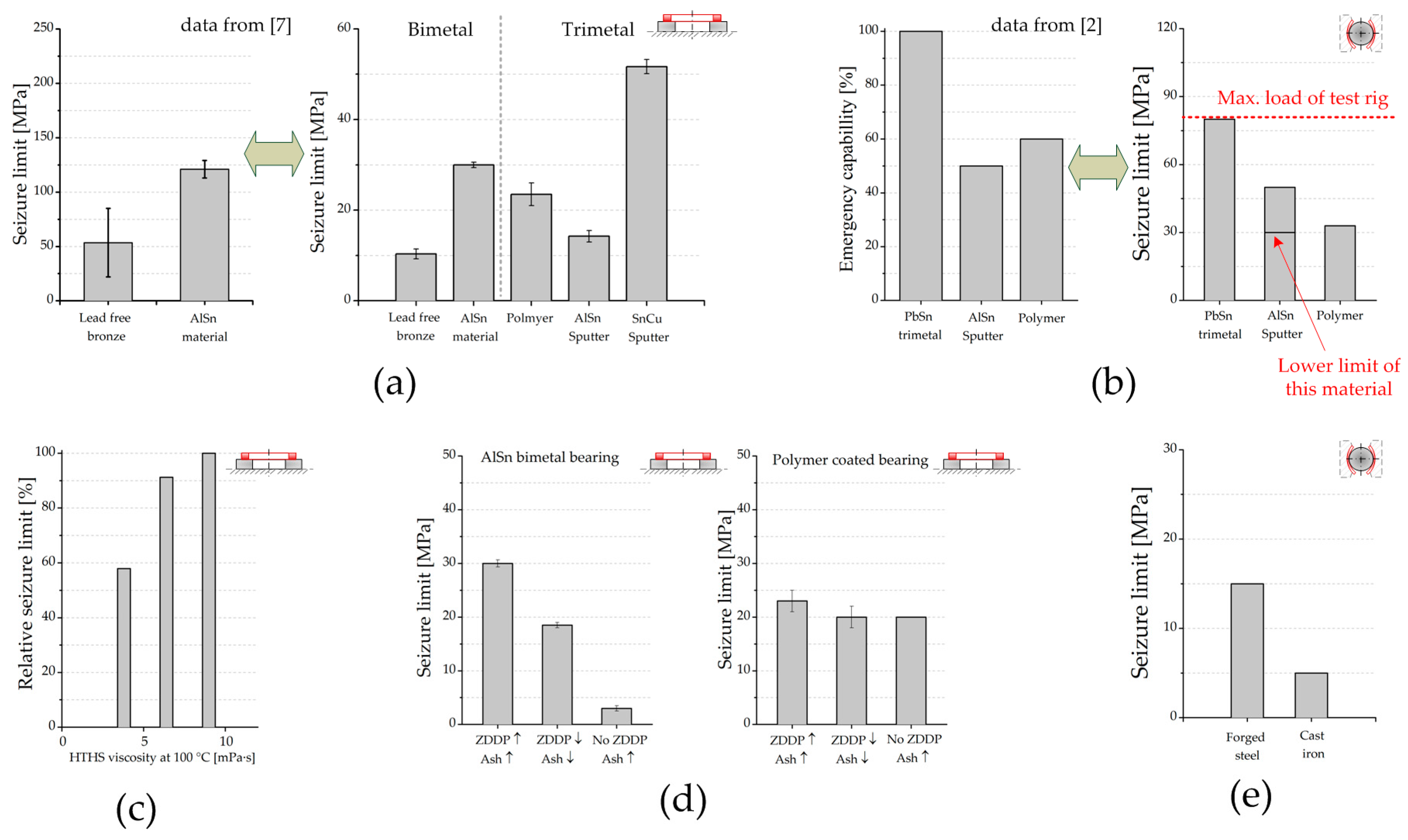
The precise detection of tribological processes and high reproducibility of the test set ups can be used for high quality screening with low scatter of various journal bearing systems. Figure 12 shows seizure performance and emergency running properties of various journal bearing systems depending on bearing material, shaft material, and lubricant; therefore, it outlines the possibilities for specific studies in this area of interest by using the herein presented test methodologies (the data have been determined in seizure load step test procedures as shown in Figure 10a,b). Figure 12a depicts the ranking of several bearing materials, lining materials, and coatings to withstand seizure up to critical load values and verifies the obtained results by comparison with literature ranking of bearing rigs. As for the lining materials, it can be highlighted that, unsurprisingly, AlSn materials possess higher emergency capability compared to that of harder lead free bronze material, which matches relatively results known from the literature. In the case of tribological coatings, usually applied on lining materials with insufficient tribological properties, the tested polymer overlay results in good performance with the RoD set up. Furthermore, superior performance can be achieved with a novel Sn based sputter coating, which is the result of a comprehensive optimization process to design a bearing material with enhanced emergency properties and sufficient hydrodynamic load bearing capacity.
With the aid of the bearing segment system, reliable results are obtained. This is also verified by comparison with rankings from literature (Figure 12b). Highest seizure load resistance, which means emergency running capability, is reached by using a lead based electroplated bearing. Bearing products using Al based sputter coatings or polymer overlays provide lower seizure load limits relative to the tested electroplated coating.
With the applied methodologies providing low measurement scatter, the effect of lubricant formulation (viscosity and additive formulation) on the emergency running performance of bearing systems can be visualized. As seen, the robustness of various bearing systems tested is significantly decreased using lower oil viscosities, shown in Figure 12c. Regarding additive formulation, for e.g., the decrease of Zincdialkyldithiophosphate (ZDDP) content affects the performance of AlSn bearing material negatively, whereas an optimized polymer coating is less sensitive to the decrease of protective lubricant additive amounts, see Figure 12d.
In addition, the influence of the shaft counterpart design (material/surface structures) can be investigated using the given test methodologies. In Figure 12e, a comparison of the performance of systems using a forged steel counterpart and systems using a cast iron counterpart is depicted. It can be seen that the forged steel shaft provides higher seizure resistance. The differences can be traced back to abrasion damages, induced by metal flaps with burrs around the graphite inclusions in the case of cast iron. However, by means of optimized surface treatment of the cast iron material, this negative effect can be eliminated. Further details can be found in a corresponding in-depth study by the authors published in [27].
4. Summary
The current paper outlines test possibilities of journal bearing systems on damage equivalent laboratory test methodologies on tribometer rigs by using specific research examples. It has been clearly emphasized that the proposed methodologies are able to highly resolve friction phenomena, wear processes, and seizure events of journal bearing systems on a reduced realism scale. In particular, the following effects have been demonstrated:
- Impact of bearing material, viscosity level, and additive formulation on friction losses of bearing systems has been shown. In this regard, the difference between an AlSn bimetal bearing and an advanced polymer coated bearing and the difference between various viscosity levels and oils with and without surface active additives have been highlighted.
- Start stop wear performance of various bearing materials, prevention of mixed friction wear processes by specific bearing material design, as well as bearing wear prediction with the aid of combining simulation and testing have been presented.
- The possibility for in-depth studies of bearing seizure with secured transferability into real applications showing the impact of the used bearing material and the shaft counterpart, as well as the effect of viscosity level and additive design of engine oils, have been highlighted.
From the obtained results, it can be deduced that there is still immense potential in optimizing bearing systems in terms of higher tribological robustness as well as low friction performance.
Acknowledgments
Financial support by the Austrian Federal Government (in particular from Bundesministerium für Verkehr, Innovation und Technologie and Bundesministerium für Wissenschaft, Forschung und Wirtschaft) represented by Österreichische Forschungsförderungsgesellschaft mbH and the Styrian and the Tyrolean Provincial Government, represented by Steirische Wirtschaftsförderungsgesellschaft mbH and Standortagentur Tirol, within the framework of the COMET Funding Programme is gratefully acknowledged. Furthermore, the support of Miba Gleitlager Austria GmbH and Infineum UK Ltd., by providing bearing material products and lubricants, is greatly acknowledged.
Author Contributions
All three authors have contributed substantially to the work presented in this paper and made significant contributions concerning the development of the presented test methodologies. Additionally, Florian Summer conceived, designed, and conducted the experiments, wrote the main part of the paper, and analyzed the test data; Philipp Bergmann contributed to writing the paper as well as in proof reading the manuscript and conducted the simulations; Florian Grün consulted regarding the design of the experiments and interpretation of the test data and also proof read the manuscript.
Conflicts of Interest
The authors declare no conflict of interest.
Abbreviations
| BS | Bearing segment |
| CAD | Computer aided design |
| CI | Corrosion inhibitor |
| COF, μ | Coefficient of friction |
| CP | Contact potential (contact resistance measurement) |
| HTHS | High-temperature high-shear viscosity |
| RoD | Ring-on-disc |
| RT | Room temperature |
| TEHL | Thermoelastohydrodynamic lubrication |
| ZDDP | Zincdialkyldithiophosphate |
| C | Empirical constant [J/m3] |
| Fasp | Asperity load [N] |
| Fext | External load [N] |
| Fhyd | Hydrodynamic load [N] |
| h0 | Initial lubrication gap height [µm] |
| K | Empiric constant |
| pm | Flow pressure [MPa] |
| P, pn | External (normal) pressure [MPa] |
| p | Asperity contact pressure [MPa] |
| s | Sliding distance [m] |
| T | Temperature [°C] |
| u | Solid deformation [µm] |
| v | Sliding speed [m/s] |
| Vwear | Wear volume [mm3] |
| W | Worn volume [mm3] |
| Wr, w | Wear height [µm] |
References
- Aufischer, R.; Hager, G.; Hamdard, K.; Offenbecher, M. Bearing Technology Combinations for Low Friction Cranktrains. MTZ Ind. 2016, 6, 56–63. [Google Scholar] [CrossRef]
- Aufischer, R. Lager in Verbrennungsmotoren. In Handbuch Verbrennungsmotor; Vieweg+Teubner: Wiesbaden, Germany, 2010; Volume 5. [Google Scholar]
- Affenzeller, J.; Gläser, H. Lagerung und Schmierung von Verbrennungsmotoren; Springer: Heidelberg, Germany, 1996. [Google Scholar]
- Czichos, H.; Habig, K.H. Tribologie–Handbuch: Tribometrie, Tribomaterialien, Tribotechnik, 3rd ed.; Vieweg & Teubner: Wiesbaden, Germany, 2010. [Google Scholar]
- Vencl, A.; Rac, A. Diesel engine crankshaft journal bearings failures: Case study. Eng. Fail. Anal. 2014, 44, 217–228. [Google Scholar] [CrossRef]
- Forstner, C.; Mairhofer, G. Application oriented bearing testing. In Proceedings of the 25th CIMAC World Congress on Combustion Engine Technology, Vienna, Austria, 21–24 May 2007. [Google Scholar]
- Aufischer, R.; Walker, R.; Offenbecher, M.; Hager, G. Modular Bearing Designs to Cope with the New Engine Designs Demanding High Performance, Lead-Free Solutions, and Robustness. J. Eng. Gas Turbines Power 2014, 136, 122505. [Google Scholar] [CrossRef]
- Mergen, R.; Gumpoldsberger, G.; Grün, F.; Godor, I.; Langbein, F. Aluminium-base bearings—Performance, limitations, new developments. In Proceedings of the 25th CIMAC World Congress on Combustion Engine Technology, Vienna, Austria, 21–24 May 2007. [Google Scholar]
- Sharma, S.C.; Hargreaves, D. A suitable method for journal bearing wear measurement. Ind. Lubr. Tribol. 2014, 66, 15–22. [Google Scholar] [CrossRef]
- Farfán-Cabrera, L.I.; Gallardo-Hernández, E.A. Wear evaluation of journal bearings using an adapted micro-scale abrasion tester. Wear 2017, 376, 1841–1848. [Google Scholar] [CrossRef]
- Kagohara, Y.; Takayanagi, S.; Haneda, S.; Fujita, M.; Iwai, Y. Tribological property of plain bearing with low frictional layer. Tribol. Int. 2009, 42, 1800–1806. [Google Scholar] [CrossRef]
- Feyzullahoğlu, E.; Şakiroğlu, N. The wear of aluminium-based journal bearing materials under lubrication. Mater. Des. (1980–2015) 2010, 31, 2532–2539. [Google Scholar] [CrossRef]
- Pondicherry, K.S.; Grün, F.; Gódor, I.; Bertram, R.; Offenbecher, M. Applicability of ring-on-disc and pin-on-plate test methods for Cu–steel and Al–steel systems for large area conformal contacts. Lubr. Sci. 2013, 25, 231–247. [Google Scholar] [CrossRef]
- Grün, F. Functionality of Heterogeneous Sliding Materials for Conformal Contacts. Habilitation Thesis, Montanuniversität Leoben, Leoben, Austria, 2012. [Google Scholar]
- Gebretsadik, D.W.; Hardell, J.; Prakash, B. Friction and wear characteristics of different Pb-free bearing materials in mixed and boundary lubrication regimes. Wear 2015, 340–341, 63–72. [Google Scholar] [CrossRef]
- Gebretsadik, D.W.; Hardell, J.; Prakash, B. Tribological performance of tin-based overlay plated engine bearing materials. Tribol. Int. 2015, 92, 281–289. [Google Scholar] [CrossRef]
- Furey, M.J. Metallic Contact and Friction between Sliding Surfaces. ASLE Trans. 1961, 4, 1–11. [Google Scholar] [CrossRef]
- Bergmann, P.; Grün, F.; Summer, F.; Godor, I.; Stadler, G. Expansion of the Metrological Visualization Capability by the Implementation of Acoustic Emission Analysis. Adv. Tribol. 2017, 2017, 17. [Google Scholar] [CrossRef]
- Grün, F.; Gódor, I.; Gärtner, W.; Eichlseder, W. Tribological performance of thin overlays for journal bearings. Tribol. Int. 2011, 44, 1271–1280. [Google Scholar] [CrossRef]
- Grün, F.; Summer, F.; Pondicherry, K.S.; Gódor, I.; Offenbecher, M.; Lainé, E. Tribological functionality of aluminium sliding materials with hard phases under lubricated conditions. Wear 2013, 298–299, 127–134. [Google Scholar] [CrossRef]
- Adam, A.; Prefot, M.; Wilhelm, M. Crankshaft bearings for engines with start-stop systems. MTZ Worldw. 2010, 71, 22–25. [Google Scholar] [CrossRef]
- Summer, F.; Grün, F.; Offenbecher, M.; Taylor, S.; Lainé, E. Tribology of journal bearings: Start stop operation as life-time factor. Tribol. Schmier. 2017, 64, 44–54. [Google Scholar]
- Archard, J.F.; Hirst, W. The wear of metals under unlubricated conditions. Proc. R. Soc. Lond. Ser. A Math. Phys. Sci. 1956, 236, 397–410. [Google Scholar] [CrossRef]
- Bergmann, P.; Grün, F.; Gódor, I.; Herbst, K. Methodology Development for Numerical Evaluation of Wear in Tribological Contacts. In Proceedings of the microCAD 2016, Miskolc, Hungary; 2016; Volume 6, pp. 5–14. [Google Scholar]
- Greenwood, J.A.; Williamson, J.B.P. Contact of nominally flat surfaces. Proc. R. Soc. Lond. Ser. A 1966, 295, 300–319. [Google Scholar] [CrossRef]
- Totten, G.E.; Liang, H. Mechanical Tribology: Materials, Characterization, and Applications; CRC Press: Boca Raton, FL, USA, 2004. [Google Scholar]
- Summer, F.; Grün, F.; Schiffer, J.; Gódor, I.; Papadimitriou, I. Tribological study of crankshaft bearing systems: Comparison of forged steel and cast iron counterparts under start–stop operation. Wear 2015, 338–339, 232–241. [Google Scholar] [CrossRef]
Figure 1.
Journal bearing test possibilities.

Figure 2.
Experimental approach. COF = coefficient of friction.

Figure 3.
Ring-on-disc experimental methodology (plain contact): (a) Set up and test area/skills; (b) Implementation of the set up on a tribometer test rig TE92. CP = electrical resistance measurement.
Figure 3.
Ring-on-disc experimental methodology (plain contact): (a) Set up and test area/skills; (b) Implementation of the set up on a tribometer test rig TE92. CP = electrical resistance measurement.
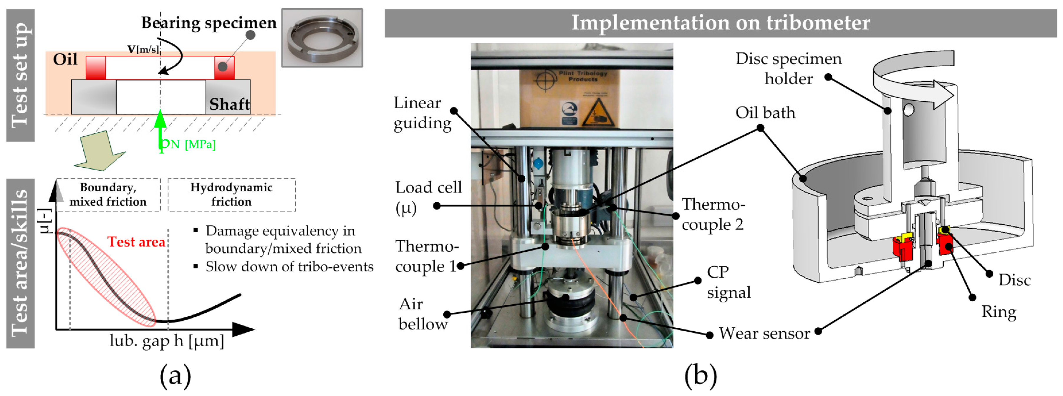
Figure 4.
Bearing segment test methodology: (a) Set up and test area/skills; (b) Implementation of the set up on a tribometer test rig TE92. CP = electrical resistance measurement.
Figure 4.
Bearing segment test methodology: (a) Set up and test area/skills; (b) Implementation of the set up on a tribometer test rig TE92. CP = electrical resistance measurement.
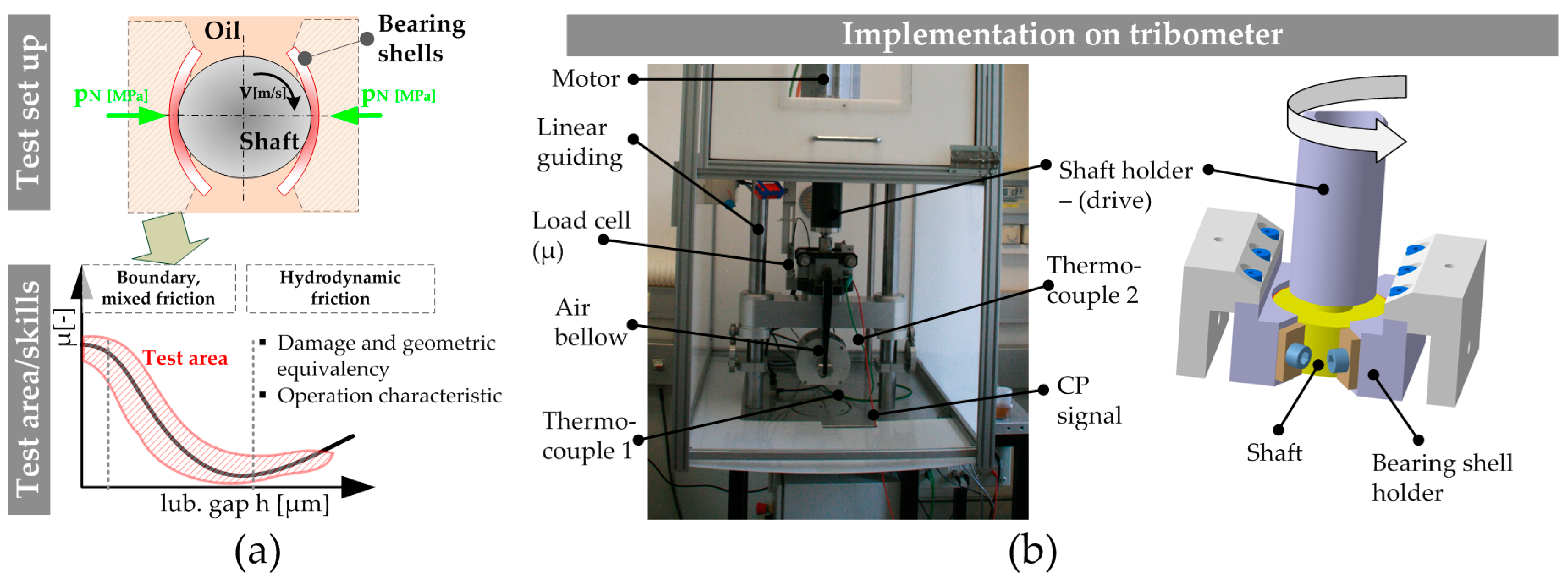
Figure 5.
Tribometric test plots focusing on friction performance: (a) Bearing segment test system showing the effect of various bearing materials; (b) Bearing segment test system showing the effect of different oil viscosities; (c) Friction curves obtained with ring-on-disc (RoD) set up showing differences owing to specific material optimization; (d) Mixed friction performance with different oil additive formulation obtained with RoD set up.
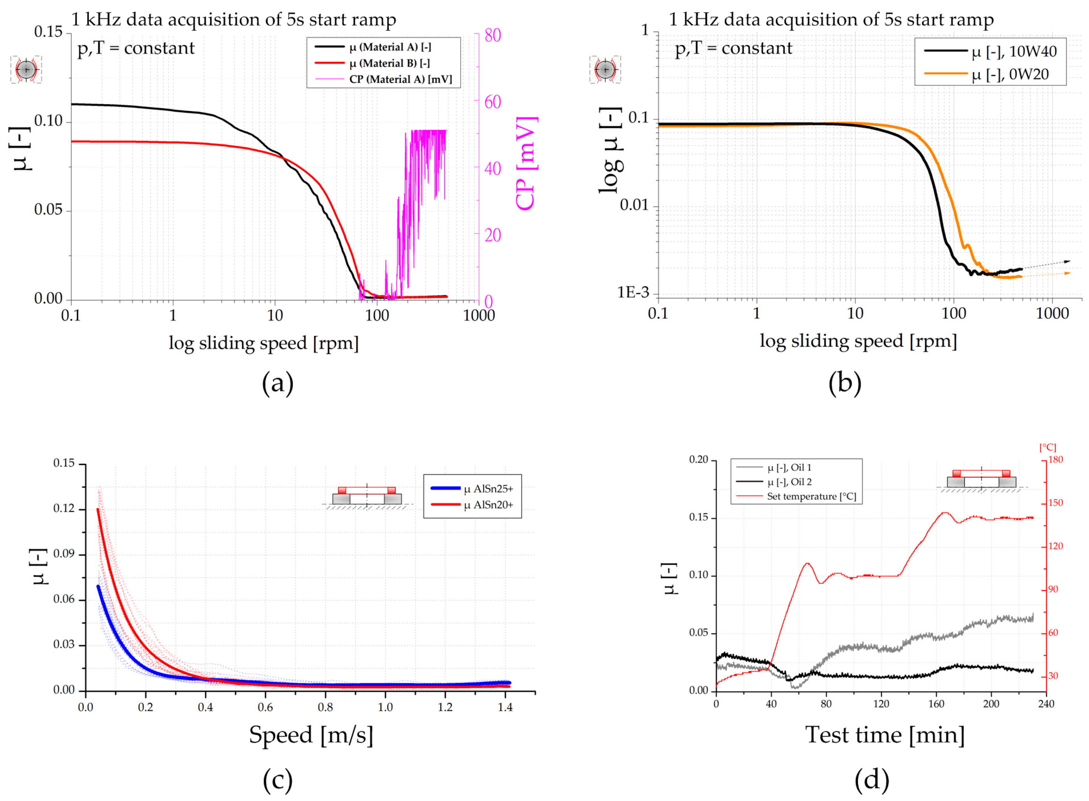
Figure 6.
Elucidation of wear processes: (a) Mixed friction sliding of lead free bronze lining determined with RoD set up; (b) Mixed friction sliding of lead free bronze lining coated with a polymer overlay determined with RoD set up; (c) Start stop wear evolution of two bearing materials obtained with bearing segment (BS) system; (d) Comparison of bearing shells after start stop testing for similar test conditions.

Figure 7.
Tribo-corrosive events during mixed friction sliding obtained with RoD set up: (a) Light microscopy surface picture of corrosive layer on lead free bronze; (b) Comparison of bronze disc specimen tested with different oil formulations with Oil D containing special corrosion protector additives; (c) Tribometric data.
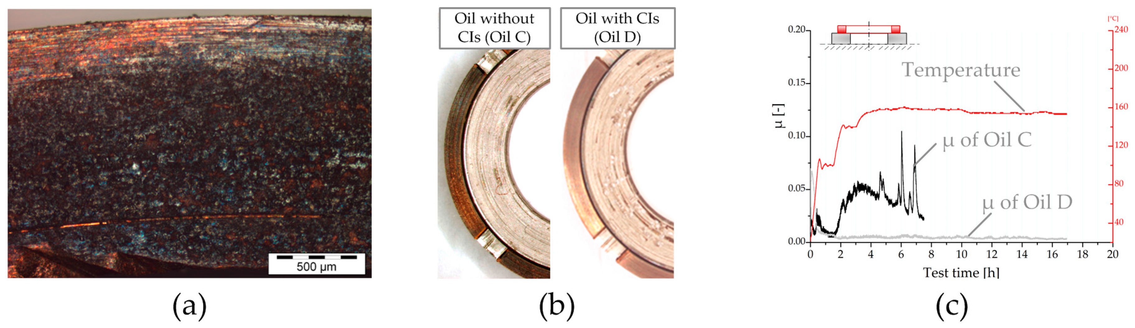
Figure 8.
Model and boundaries for the numerical wear assessment. Boundary A: action of external force; boundary B: application of Reynolds, asperity contact, and wear equations; boundary C, D, and E: roller conditions representing the guidance of the surrounding structure.
Figure 8.
Model and boundaries for the numerical wear assessment. Boundary A: action of external force; boundary B: application of Reynolds, asperity contact, and wear equations; boundary C, D, and E: roller conditions representing the guidance of the surrounding structure.
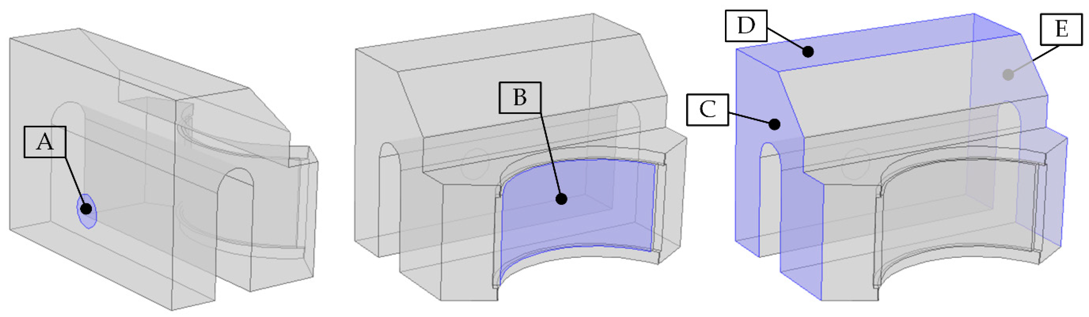
Figure 9.
Quantities of the numerical wear scenario.

Figure 10.
Tribometric seizure test plots: (a) RoD test set up using AlSn trimetal bearing; (b) Bearing segment test set up using AlSn trimetal bearing.
Figure 10.
Tribometric seizure test plots: (a) RoD test set up using AlSn trimetal bearing; (b) Bearing segment test set up using AlSn trimetal bearing.
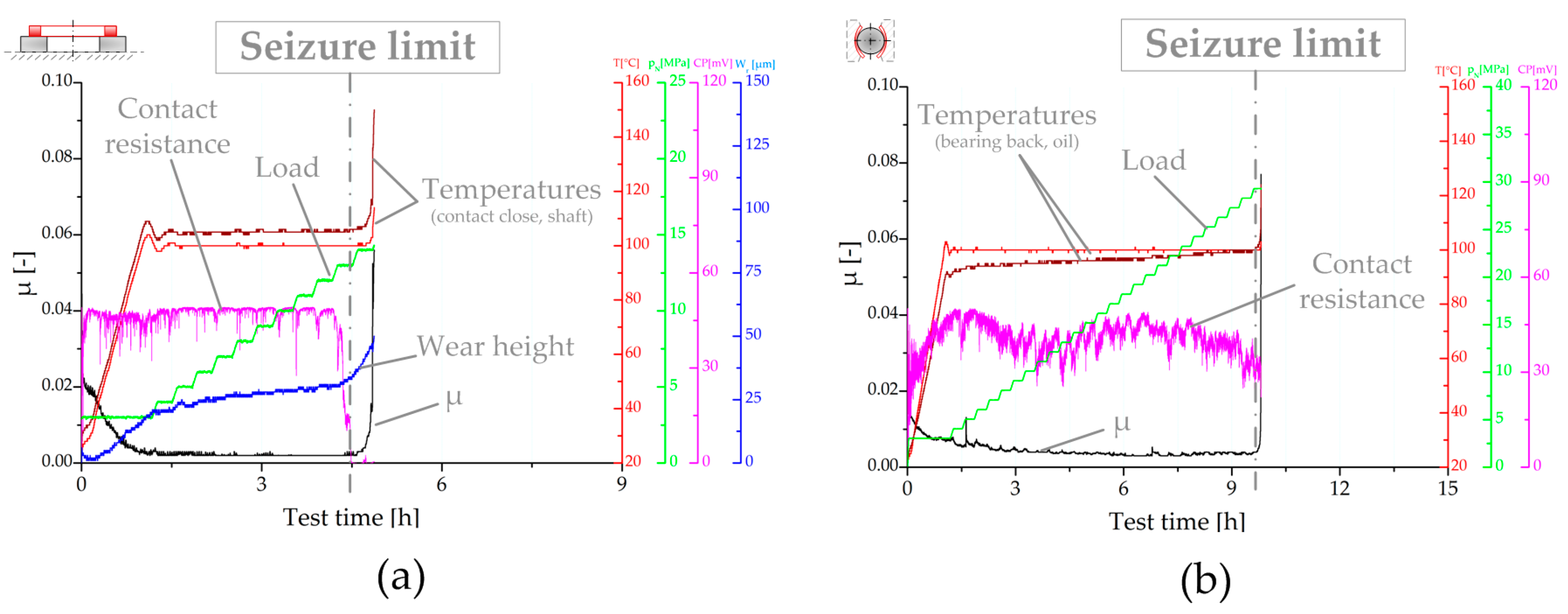
Figure 11.
Surface structures after RoD seizure tests: (a) Bearing disc specimen; (b) Corresponding shaft counterpart.
Figure 11.
Surface structures after RoD seizure tests: (a) Bearing disc specimen; (b) Corresponding shaft counterpart.
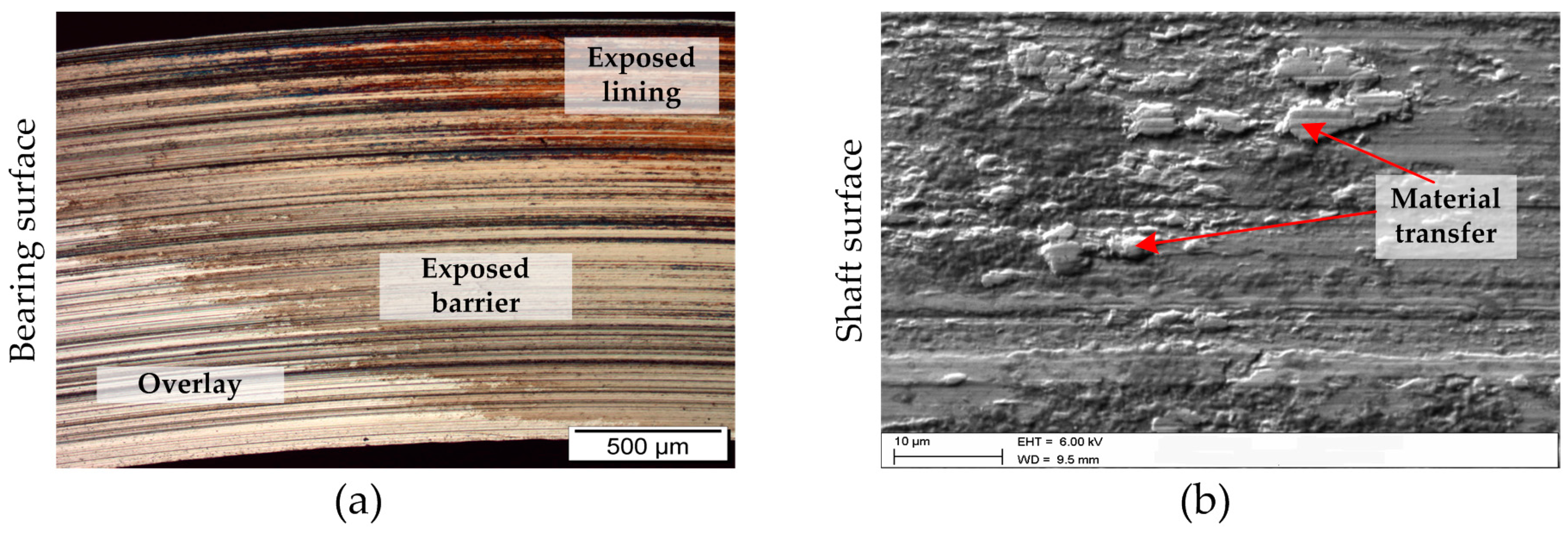
Figure 12.
Impacts on seizure performances of bearing systems: (a) RoD system—effect of bearing material compared with data from [7]; (b) BS system—effect of bearing material compared with data from [2]; (c) RoD system—effect of oil viscosity; (d) RoD system—effect of additive formulation for various bearing materials; (e) BS system—effect of shaft counterpart.

© 2017 by the authors. Licensee MDPI, Basel, Switzerland. This article is an open access article distributed under the terms and conditions of the Creative Commons Attribution (CC BY) license (http://creativecommons.org/licenses/by/4.0/).
Share and Cite
MDPI and ACS Style
Summer, F.; Bergmann, P.; Grün, F. Damage Equivalent Test Methodologies as Design Elements for Journal Bearing Systems. Lubricants 2017, 5, 47. https://doi.org/10.3390/lubricants5040047
AMA Style
Summer F, Bergmann P, Grün F. Damage Equivalent Test Methodologies as Design Elements for Journal Bearing Systems. Lubricants. 2017; 5(4):47. https://doi.org/10.3390/lubricants5040047
Chicago/Turabian StyleSummer, Florian, Philipp Bergmann, and Florian Grün. 2017. "Damage Equivalent Test Methodologies as Design Elements for Journal Bearing Systems" Lubricants 5, no. 4: 47. https://doi.org/10.3390/lubricants5040047
Note that from the first issue of 2016, this journal uses article numbers instead of page numbers. See further details here.